EP2367066B1 - Ladegerät - Google Patents
Ladegerät Download PDFInfo
- Publication number
- EP2367066B1 EP2367066B1 EP11157255.8A EP11157255A EP2367066B1 EP 2367066 B1 EP2367066 B1 EP 2367066B1 EP 11157255 A EP11157255 A EP 11157255A EP 2367066 B1 EP2367066 B1 EP 2367066B1
- Authority
- EP
- European Patent Office
- Prior art keywords
- shutter
- winding
- charging
- photosensitive member
- corona charger
- Prior art date
- Legal status (The legal status is an assumption and is not a legal conclusion. Google has not performed a legal analysis and makes no representation as to the accuracy of the status listed.)
- Not-in-force
Links
Images


Classifications
-
- G—PHYSICS
- G03—PHOTOGRAPHY; CINEMATOGRAPHY; ANALOGOUS TECHNIQUES USING WAVES OTHER THAN OPTICAL WAVES; ELECTROGRAPHY; HOLOGRAPHY
- G03G—ELECTROGRAPHY; ELECTROPHOTOGRAPHY; MAGNETOGRAPHY
- G03G15/00—Apparatus for electrographic processes using a charge pattern
- G03G15/02—Apparatus for electrographic processes using a charge pattern for laying down a uniform charge, e.g. for sensitising; Corona discharge devices
- G03G15/0291—Apparatus for electrographic processes using a charge pattern for laying down a uniform charge, e.g. for sensitising; Corona discharge devices corona discharge devices, e.g. wires, pointed electrodes, means for cleaning the corona discharge device
-
- G—PHYSICS
- G03—PHOTOGRAPHY; CINEMATOGRAPHY; ANALOGOUS TECHNIQUES USING WAVES OTHER THAN OPTICAL WAVES; ELECTROGRAPHY; HOLOGRAPHY
- G03G—ELECTROGRAPHY; ELECTROPHOTOGRAPHY; MAGNETOGRAPHY
- G03G15/00—Apparatus for electrographic processes using a charge pattern
- G03G15/02—Apparatus for electrographic processes using a charge pattern for laying down a uniform charge, e.g. for sensitising; Corona discharge devices
-
- G—PHYSICS
- G03—PHOTOGRAPHY; CINEMATOGRAPHY; ANALOGOUS TECHNIQUES USING WAVES OTHER THAN OPTICAL WAVES; ELECTROGRAPHY; HOLOGRAPHY
- G03G—ELECTROGRAPHY; ELECTROPHOTOGRAPHY; MAGNETOGRAPHY
- G03G21/00—Arrangements not provided for by groups G03G13/00 - G03G19/00, e.g. cleaning, elimination of residual charge
-
- G—PHYSICS
- G03—PHOTOGRAPHY; CINEMATOGRAPHY; ANALOGOUS TECHNIQUES USING WAVES OTHER THAN OPTICAL WAVES; ELECTROGRAPHY; HOLOGRAPHY
- G03G—ELECTROGRAPHY; ELECTROPHOTOGRAPHY; MAGNETOGRAPHY
- G03G2215/00—Apparatus for electrophotographic processes
- G03G2215/02—Arrangements for laying down a uniform charge
- G03G2215/026—Arrangements for laying down a uniform charge by coronas
- G03G2215/027—Arrangements for laying down a uniform charge by coronas using wires
-
- H—ELECTRICITY
- H01—ELECTRIC ELEMENTS
- H01T—SPARK GAPS; OVERVOLTAGE ARRESTERS USING SPARK GAPS; SPARKING PLUGS; CORONA DEVICES; GENERATING IONS TO BE INTRODUCED INTO NON-ENCLOSED GASES
- H01T19/00—Devices providing for corona discharge
Definitions
- the present invention relates to a charging device according to the preamble of claim 1.
- an image has been conventionally formed through an electrophotographic process including steps of charging, exposure, development and transfer.
- steps of charging, exposure, development and transfer a photosensitive member has been electrically charged uniformly to a potential of a predetermined polarity by a corona charger provided closely to the photosensitive member.
- corona charger In the charging step using the corona charger, corona discharge is utilized, so that an electric discharge product such as ozone (O 3 ) or nitrogen oxides (NO X ) is generated.
- JP-A-2008-046297 has proposed opening and closing movement of the shutter along a longitudinal direction of the corona charger.
- the corona charger is disposed closely to the photosensitive member surface and therefore there is a need to provide the shutter in a narrow gap. In such a constitution, there is a possibility that the shutter is contacted to a photosensitive drum when the shutter is moved for being opened and closed.
- the sheet containing fiber is liable to be deformed by a change in environment (particularly moisture absorption in a high temperature and high humidity environment).
- the nonwoven fabric has a tendency to be curled generally with respect to a direction (flow) of the fiber of the nonwoven fabric as an axis when the nonwoven fabric is left standing for a long time in the high temperature and high humidity environment.
- the woven fabric and the knitted fabric have a tendency to be curled with respect to a direction, as an axis, in which a density of a weave texture (a space between threads of the fabric) is low (coarse).
- JP S60 007447 A shows a generic charging device according to the preamble of claim 1, comprising a corona charger; a shutter of a sheet for shielding an opening of said corona charger, said sheet having such a property that it is curled about an axis when said shutter absorbs moisture; and winding-up means for winding up said shutter.
- the object of the present invention is achieved by a charging device having the features of claim 1.
- the image forming apparatus in this embodiment is a laser beam printer of an electrophotographic type.
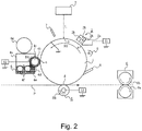
- a charging device 2 As shown in Figure 2 , a charging device 2, an exposure device 3, a potential measuring device 7, a developing device 4, a transferring device 5, a cleaning device 8, and an optical discharging device 9 are provided in this order around a photosensitive member (image bearing member) 1 along a rotational direction (indicated by an arrow R1) of the photosensitive member 1. Further, a fixing device 6 is provided downstream of the transferring device 5 with respect to a conveyance direction of a recording material P.
- the photosensitive member 1 in this embodiment as the image bearing member is a cylindrical(drum-type)electrophotographic photosensitive member having a photosensitive layer of a negatively chargeable organic optical semiconductor.
- the photosensitive member 1 of the drum type has a diameter of 84 mm and a longitudinal length of 380 mm. Further, the photosensitive member 1 is rotationally driven in the arrow R1 direction about a center shaft (not shown) at a process speed (peripheral speed) of 500 mm/sec.
- the charging device 2 in this embodiment is, as shown in Figure 2 , a corona charger of a scorotron type including a discharging wire 2h, a U-shaped electroconductive shield 2b which is provided so as to surround the discharging wire, and a grid electrode 2a provided at an opening of the shield 2b.
- the corona charger 2 including two discharging wires 2h and a partition wall provided between the two discharging wires 2h is used.
- the corona charger 2 is provided along a generatrix direction of the photosensitive member 1. Therefore, a longitudinal direction of the corona charger 2 is parallel to an axial (shaft) direction of the photosensitive member 1.
- the grid electrode 2a is disposed along the circumferential surface of the photosensitive member so that a central portion thereof with respect to a widthwise (short) direction (a photosensitive member movement direction) is separated from the photosensitive member in a larger distance than that at both end portions thereof.
- the corona charger 2 can be brought nearer to the photosensitive member 1, so that a charging efficiency can be improved.
- a charging bias application source S1 for applying a charging bias is connected, so that the corona charger 2 has the function of uniformly charging the surface of the photosensitive member 1 to a potential of a negative polarity at a charging position a by the charging bias applied from the application source S1.
- the charging bias of a DC voltage is applied to the discharging wires 2h and the grid electrode 2a.
- the corona charger 2 in this embodiment is provided with a charging shutter for preventing the electric discharge product from being deposited on the photosensitive member 1.
- a charging shutter for preventing the electric discharge product from being deposited on the photosensitive member 1.
- Image forming devices image forming portions relating to image forming steps such as exposure, development and transfer will be briefly described below.
- the exposure device 3 in this embodiment is a laser beam scanner including a semiconductor laser for irradiating the photosensitive member 1 charged by the corona charger 2 with laser light L. Specifically, on the basis of an image signal (information) sent from a host computer connected to the image forming apparatus through a network cable, the image exposure device 3 outputs the laser light L. The charged surface of the photosensitive member 1 is exposed to the laser light L along a main scan direction at an exposure position b. By repeating the exposure along the main scan direction during the rotation of the photosensitive member 1, of the charged surface of the photosensitive member 1, a portion irradiated with the laser light L is lowered in potential, so that an electrostatic latent image is formed correspondingly to the image information.
- the main scan direction means a direction parallel to the generatrix of the photosensitive member 1 and a sub-scan direction means a direction parallel to the rotational direction of the photosensitive member 1.
- the developing device 4 deposits a developer (toner) on the electrostatic latent image formed on the photosensitive member 1 by the charging device 2 and the exposure device 3 to visualize the latent image.
- the developing device in this embodiment employs a two component magnetic brush developing method and also employs a reverse developing method.
- a developing bias application source S2 is connected to the developing sleeve 4b, and the toner in the developer carried on the surface of the developing sleeve 4b is selectively deposited correspondingly to the electrostatic latent image on the photosensitive member 1 by an electric field generated by a developing bias applied from the application source S2.
- the electrostatic latent image is developed as the toner image.
- the toner is deposited at an exposed portion (laser light irradiation portion) on the photosensitive member 1, so that the electrostatic latent image is reversely developed.
- the transfer device 5 in this embodiment includes a transfer roller 5 as shown in Figure 2 .
- the transfer roller 5 is urged against the surface of the photosensitive member 1 with a predetermined urging force to form a nip therebetween as a transfer portion d.
- the recording material P e.g., paper or a transparent film
- the transfer portion d the recording material P (e.g., paper or a transparent film) is sent from a sheet-feeding cassette with predetermined control timing.
- the recording material P sent to the transfer d is subjected to transfer of the toner image formed on the photosensitive member 1 while being nip-conveyed between the photosensitive member 1 and the transfer roller 5.
- a transfer bias (+2 KV in this embodiment) of an opposite polarity to the normal charge polarity (negative) of the toner is applied from a transfer bias application source S3.
- the fixing device 6 in this embodiment includes a fixing roller 6a and a pressing roller 6b as shown in Figure 2 .
- the recording material P on which the toner image is transferred by the transfer device 5 is conveyed to the fixing device in which the toner image is heated and pressed between the fixing roller 6a and the pressing roller 6b to be fixed on the recording material P.
- the recording material P subjected to the fixing is then discharged to the outside of the image forming apparatus.
- the cleaning device 8 in this embodiment includes, as shown in Figure 2 , a cleaning blade. After the toner image is transferred on the recording material P by the transfer device 5, untransferred toner remaining on the photosensitive member 1 surface is removed by the cleaning blade.
- the optical discharging device 9 in this embodiment includes, as shown in Figure 2 , a discharging exposure lamp. Residual charges remaining on the surface of the photosensitive member 1 subjected to the cleaning by the cleaning device 8 are removed by light irradiation by the discharging exposure lamp 9.
- a series of the image forming processes by the image forming devices described above is completed and the image forming apparatus prepares for a subsequent image forming operation.
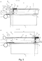
- the opening of the corona charger 2 refers to the opening formed with respect to the shield and corresponds to a charging region (W in Figure 5 ) of the corona charger 2. Therefore, the charging region W of the corona charger 2 substantially coincides with a region in which the photosensitive member 1 is electrically chargeable.
- a non-endless sheet-like shutter capable of being wound up in a roll shape by a winding-up device 11 is employed as the charger shutter 10 for covering and uncovering the opening of the corona charger 2.
- the charger shutter 10 for covering and uncovering the opening of the corona charger 2.
- the charging shutter 10 a sheet-like shutter formed of the nonwoven fabric by rayon fiber in a thickness of 150 ⁇ m is employed.
- the nonwoven fabric containing polyester fiber may also be used.
- a resin sheet (PET film) of 50 ⁇ m in thickness is provided as a protective sheet 25 having an abrasion resistance higher than that of the nonwoven fabric.
- the protective sheet 25 is not limited to the resin sheet so long as the protective sheet 25 is formed of a material which is resistive to rubbing (abrasion) move than the nonwoven fabric used for the charging shutter.
- the protective sheet 25 may only be required to possess the abrasion resistance higher than that of the charging shutter 10 in a Gakushin-type friction test using a friction (rubbing) tester defined in JIS L-0849.
- Parts (A) and (B) of Figure 5 show an open state and a closed state, respectively, of the charging shutter 10.
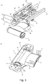
- Part (A) of Figure 3 is a perspective view showing a detail structure of an opening and closing mechanism of the charging shutter
- (B) of Figure 3 is a perspective view for illustrating a detail structure of a winding-up device.
- (A) of Figure 4 is a sectional view of the corona charger as seen from a longitudinal one end side of the corona charger
- (B) of Figure 4 is a sectional view of the winding-up device.
- a mechanism (opening and closing mechanism for moving the charging shutter in an opening (uncovering) and closing (covering) direction will be described below.
- the opening and closing mechanism of the charging shutter 10 includes a driving motor M, a winding-up device 11, a first movable member 21 for holding the charging shutter 10, a second movable member 12 for holding a cleaning member 14, and a rotatable member 13. By these members, the charger shutter 10 can be moved for being opened and closed along the longitudinal direction (the main scan direction) of the charger shutter 10.
- a shutter detecting device 15 for detecting completion of an opening operation of the charger shutter 10 is provided.
- the shutter detecting device 15 includes a photo-interrupter.
- the opening operation completion of the charger shutter 10 is detected by utilizing light-blocking of the photo-interrupter 15 by a light-blocking member 21c. That is, at the time when the photointerrupter 15 detects the light-blocking member 21c of the first movable member 21, the rotation of the driving motor M is stopped.
- a shutter fixing member 17 (leaf spring) functioning as a regulating means for regulating the shape of the charging shutter is provided so that a short direction central portion of the charging shutter is protruded toward the corona charger side more than short direction both end portions of the charging shutter.
- the shutter fixing member 17 is locked and fixed to a connecting member 21b provided integrally with the first movable member 21.
- the first movable member 21 and the second movable member (carriage) 12 include a drive transmission member 22 provided threadably mounted on the rotatable member 13 and is driving-connected with the rotatable member 13 through the drive transmission member 22. Further, the first movable member 21 and the second movable member 12 are threadably mounted so as to be movable only in the main scan direction on a rail 2c provided on the corona charger 2, thus being prevented from rotating together with the rotatable member 13.
- a spiral groove is provided and a gear 18 is connected at one end of the rotatable member 13.
- a warm gear 19 is connected to an end of the driving motor M and transmits a driving force of the driving motor M to the rotatable member 13 through an engaging portion between the warm gear 19 and the gear 18.
- the second movable member 12 is integrally provided with a connecting member 12b for holding a cleaning member 14 for cleaning the discharging wires 2h.
- the cleaning member 14 is also moved in the same direction.
- Part (A) of Figure 5 shows a state in which the charging shutter 10 is opened by winding up the charging shutter 10 as the sheet-like member so that the charging shutter 10 is moved in the X direction (opening direction).
- Part (B) of Figure 5 shows a state in which the charging shutter 10 is closed by pulling the charging shutter 10 as the sheet-like member so that the charging shutter 10 is moved in the Y direction (closing direction).
- Part (B) of Figure 4 is a sectional view showing a constitution of the winding-up device 11 as the winding-up means.
- the winding-up device 11 includes a cylindrical winding-up roller (winding-up member) 30 for fixing one end of the charging shutter 10 and for winding up the charging shutter 10, a shaft member 32 for shaft-supporting one end of the winding-up roller 30, and a shaft-supporting member 31 for shaft-supporting the other end of the winding-up roller 30. Further, the winding-up device 11 includes a parallel pin 34 which is a fixing member for fixing the shaft-supporting member 31 and the shaft member 32 and includes a spring (urging member) 33 provided in the winding-up roller 30 and engaged with the winding-up roller 30 and the shaft-supporting member 31.
- the shaft-supporting member 31 and the shaft member 32 are fixed in a non-rotatable manner, so that only the winding-uproller 30 is shaft-supported in a rotatable manner.
- the driving motor M pulls the charger shutter 10 from the winding-up roller 30 against the urging force of the spring 33 in the winding-up roller 30, so that the charger shutter 10 is moved in the Y direction.
- the charger shutter 10 when the charger shutter 10 is in a state in which the charging shutter 10 covers the entire region of the opening, the urging force toward the X direction by the spring 33 in the winding-up roller 30 is exerted on the charger shutter 10, so that the charging shutter 10 does not slack down.
- the corona charger 2 is, as described above, provided so that the central portion of the grid electrode 2a with respect to the short direction of the grid electrode 2a (the circumferential direction of the photosensitive member) is separated from the photosensitive member 1 along the circumferential surface of the photosensitive member 1 in a distance longer than that at the both end portions of the grid electrode 2a.
- a curvature shape imparting mechanism as the regulating means is provided so that the shape of the charging shutter 10 also follow (corresponds to) the shape of curvature of the circumferential surface of the photosensitive member 1.
- the curvature shape imparting mechanism for the leading end of the charging shutter 10 and the curvature shape imparting mechanism for the charging shutter 10 on the winding-up port side are provided and will be described below in this order.
- Part (A) of Figure 4 is a sectional view of the corona charger as seen from its short direction.
- the shutter fixing member 17 for fixing the charging shutter 10 to the movable member 12 is attached.
- This shutter fixing member 17 is constituted by a member having elasticity so as to follow the shape of curvature of the circumferential surface of the photosensitive member 1 when the shutter fixing member 17 is attached to the connecting member 21b.
- a rotatable member i.e., a so-called roller which is guiding member 16 is provided, as a second curvature shape imparting mechanism, for the charging shutter 10 on the winding-up port side of the winding-up device 11.
- the guiding member 16 is different from the shutter fixing member 17 and has a structure such that it guides the charging shutter 10 while being rotated by the opening and closing movement of the charging shutter 10. Therefore, the guiding member 16 can prevent an increase in load required for the opening and closing movement of the charging shutter 10 when the guiding member 16 regulates the shape of the charging shutter 10 so that as to be a desired shape of curvature. Further, the guiding member 16 is disposed at a position which is out of a winding-up range of the winding-up device 11 and is closer to the winding-up device 11 than the photosensitive member 1.
- an uppermost portion of the roller as the guiding member 16 is located closer to the corona charger 2 than the closest position (the outer circumferential surface) of the photosensitive member 1 with respect to the corona charger 2, so that the charging shutter 10 forms a sliding relation with the guiding member 16 during the opening and closing operation.
- the guiding member 16 also has the function as a shutter insertion guide for guiding the charging shutter 10 to the small gap (spacing) between the grid electrode 2a and the photosensitive member 1.
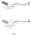
- the sheet-like charging shutter 10 as a shielding member (shutter) has a tendency to be curled in the high humidity environment.
- the winding-up of the charging shutter is characterized by an angle formed between an axial direction of the curl and the winding-up direction (shutter pulling-out direction).
- Part (A) of Figure 1 shows the winding-up direction of the charging shutter 10 about the winding-up device in this embodiment.
- the 150 ⁇ m-thick sheet-like nonwoven fabric of rayon fiber is employed as the charging shutter 10.
- This rayon nonwoven fabric has been subjected to water jet (hydraulic entangling) processing and has a directionality (flow) of orientation of the constituent rayon fiber.
- Part (B) of Figure 1 illustrates swelling and deformation of the fiber due to moisture absorption when the rayon nonwoven fabric is left standing for 2 hours in an environment of a temperature of 50 °C and a humidity of 80 %.
- the deformation of the fiber means a so-called curl with an axis such that the fiber is curled generally along the direction (flow) of the fiber.
- the nonwoven fabric containing the rayon fiber is evaluated but a similar result is obtained also with respect to the fabric of polyester fiber or the like.
- an angle ⁇ formed between the winding-up direction of the charging shutter 10 about the winding-up device 11 (a broken line in (A) of Figure 1 ) and the axial direction of curl of the charging shutter 10 in the environment described above (hereinafter referred to as a winding-up angle ⁇ ) was constituted to be 90 degrees (intersection at right angles).
- the charging shutter 10 can cover the opening of the corona charger most satisfactorily. Further, the winding-up angle ⁇ is within the range from 45 degrees to 135 degrees, the above problem can be alleviated (Table 1). When the winding-up angle ⁇ is within the range from 60 degrees to 120 degrees, the charging shutter 10 can more suitably cover the opening.
- Figure 6 shows the shape of the charging shutter 10 in the closed state in the case where the opening and closing operation is performed for a long term in the high humidity environment when the winding-up angle ⁇ is 0 degrees (or 180 degrees) which is most unsuitable.
- the curvature shape imparting mechanism as the curvature shape imparting mechanism, the curvature shape imparting mechanism for the leading end of the charging shutter 10 and the curvature shape imparting mechanism for the charging shutter 10 on the winding-up port side are provided. Therefore, as shown at cross-section (A), both end portions of the charging shutter 10 can properly cover the opening W of the corona charger while retaining a shielding (covering) range A by the effect of these curvature shape imparting mechanisms. However, in the neighborhood of the central portion of the charging shutter 10, there is no means for suppressing the curl. Therefore, as shown by a shielding range B at cross-section (B), the shielding range of the charging shutter 10 is decreased. As a result, the gap generated due to the curl was liable to be formed between the charging shutter 10 and the corona charger 2, thus resulting in a state in which the corona product was liable to be leaked to the outside.
- Table 1 is a table showing an evaluation result of a shielding area of the opening of the corona charger in the case where the nonwoven fabric of the rayon fiber is left standing for 2 hours in the high humidity environment (temperature: 50 °C, humidity: 80 %).
- the shielding area in a low humidity environment temperature: 23 °C, humidity: 5 %
- the electric discharge product is shielded in an area exceeding 97 % in the range from 45 degrees to 135 degrees, thus being shielded satisfactorily. Further, in the range from 60 degrees to 120 degrees, the area exceeding 99 % is shielded.
- Table 1 ⁇ (DEG.) 0 30 45 60 90 120 135 150 180 Evaluation x ⁇ ⁇ ⁇ ⁇ ⁇ ⁇ ⁇ ⁇ x
- the evaluation was made by a decrease (%) in shielding area due to the curl in the high humidity environment when the shielding area in the low humidity environment was 100 %.
- the nonwoven fabric of the rayon fiber is described as an example of the material for the charging shutter 10 but the present invention is also applicable to materials other than the nonwoven fabric so long as the materials cause the curl of the charging shutter material in the high humidity environment.
- the charging shutter has a front surface and a back surface. That is, the sheet placed on a flat surface becomes concave or convex depending on the type of the surfaces of the sheet (charging shutter). For that reason, in the constitution in which the axis of the curl of the charging shutter and the longitudinal direction of the corona charger intersect at substantially right angles, the following problem arises when the type (front/back) of the surfaces of the sheet is not taken into consideration. That is, when the charging shutter is curled by moisture absorption so as to be convex toward the photosensitive member, a possibility of friction of the charging shutter with the photosensitive member becomes high ((A) of Figure 7 ).
- the type of the surfaces of the sheet may preferably be considered so that the longitudinal central portion of the charging shutter is convex toward the discharging wires when the charging shutter is curled by the moisture absorption ((B) of Figure 7 ).
- the contact of the charging shutter with the photosensitive member can be suppressed. That is, by taking the type of surfaces of the charging shutter into consideration, it is possible to suppress the contact of the charging shutter with the photosensitive member while covering the opening so that the electric discharge product cannot be deposited on the photosensitive member.
- the charging shutter is urged by the winding-up device, in the direction in which the curl is suppressed, while being urged by the leaf spring. For that reason, even in the case where the charging shutter is deformed (curled) by the moisture absorption the charging shutter is configured to less slide on the photosensitive member or the grid electrode.
- the corona charger is used for substantially uniformly charging the photosensitive member in a pre-step for forming the electrostatic image on the photosensitive member is described but the present invention is not limited thereto.
- the present invention is similarly applicable to the case where the corona charger is used for electrically charging the toner image formed on the photosensitive member.
- a charging device includes a corona charger; a shutter of a sheet for shielding an opening of said corona charger, the sheet having such a property that it is curled about an axis when said shutter absorbs moisture; and a winding-up device for winding up the shutter.
- the axis and a winding-up direction in which the shutter is wound up by the winding-up means form an angle therebetween from 45 degrees to 135 degrees.
Landscapes
- Physics & Mathematics (AREA)
- Engineering & Computer Science (AREA)
- Plasma & Fusion (AREA)
- General Physics & Mathematics (AREA)
- Electrostatic Charge, Transfer And Separation In Electrography (AREA)
Claims (4)
- Aufladungsvorrichtung (2), die Folgendes aufweist:eine Koronaaufladevorrichtung (2);eine Blende (10) eines Blatts zum Abschirmen einer Öffnung der Koronaaufladevorrichtung (2), wobei das Blatt eine derartige Eigenschaft hat, dass es sich um eine Achse einrollt, wenn die Blende (10) Feuchtigkeit aufnimmt; undeine Aufwickeleinrichtung (11) zum Aufwickeln der Blende (10),dadurch gekennzeichnet, dassdie Achse und eine Aufwickelrichtung, in der die Blende (10) durch die Aufwickeleinrichtung (11) um die Aufwickeleinrichtung (11) herum aufgewickelt wird, einen Winkel (θ) zwischen ihnen von 45 Grad bis 135 Grad ausbilden, wobei die Aufwickelrichtung zu einer Blendenherausziehrichtung korrespondiert.
- Aufladungsvorrichtung (2) nach Anspruch 1, wobei die Aufwickeleinrichtung (11) die Blende (10) in Bezug auf eine Längsrichtung der Koronaaufladevorrichtung (2) aufwickelt und die Blende (10) in die Aufwickelrichtung der Blende (10) drängt.
- Aufladungsvorrichtung (2) nach Anspruch 1, wobei die Blende (10) ein Vliesgewebe ist.
- Aufladungsvorrichtung (2) nach Anspruch 1, wobei, wenn sich die Blende (10) durch die Feuchtigkeitsaufnahme einrollt, die Blende (10) zu einem Entladungsdraht (2h), der an der Koronaaufladevorrichtung (2) vorgesehen ist, hin konvex ist.
Applications Claiming Priority (1)
| Application Number | Priority Date | Filing Date | Title |
|---|---|---|---|
| JP2010052019A JP5451465B2 (ja) | 2010-03-09 | 2010-03-09 | 帯電装置 |
Publications (3)
| Publication Number | Publication Date |
|---|---|
| EP2367066A2 EP2367066A2 (de) | 2011-09-21 |
| EP2367066A3 EP2367066A3 (de) | 2016-03-09 |
| EP2367066B1 true EP2367066B1 (de) | 2017-06-21 |
Family
ID=44202195
Family Applications (1)
| Application Number | Title | Priority Date | Filing Date |
|---|---|---|---|
| EP11157255.8A Not-in-force EP2367066B1 (de) | 2010-03-09 | 2011-03-08 | Ladegerät |
Country Status (5)
| Country | Link |
|---|---|
| US (1) | US8554112B2 (de) |
| EP (1) | EP2367066B1 (de) |
| JP (1) | JP5451465B2 (de) |
| KR (1) | KR101313997B1 (de) |
| CN (1) | CN102193385B (de) |
Families Citing this family (6)
| Publication number | Priority date | Publication date | Assignee | Title |
|---|---|---|---|---|
| JP5404001B2 (ja) * | 2008-11-05 | 2014-01-29 | キヤノン株式会社 | 帯電装置 |
| WO2011111160A1 (ja) * | 2010-03-09 | 2011-09-15 | キヤノン株式会社 | 帯電装置 |
| JP5451464B2 (ja) * | 2010-03-09 | 2014-03-26 | キヤノン株式会社 | 帯電装置 |
| JP5713721B2 (ja) * | 2010-03-09 | 2015-05-07 | キヤノン株式会社 | 帯電装置、コロナ帯電器および画像形成装置 |
| CN104220937B (zh) * | 2012-04-18 | 2017-09-12 | 佳能株式会社 | 充电装置 |
| JP6039317B2 (ja) * | 2012-08-31 | 2016-12-07 | キヤノン株式会社 | 画像形成装置 |
Family Cites Families (14)
| Publication number | Priority date | Publication date | Assignee | Title |
|---|---|---|---|---|
| JPS607447A (ja) * | 1983-06-27 | 1985-01-16 | Toppan Printing Co Ltd | 帯電方法 |
| JPS61221768A (ja) * | 1985-03-27 | 1986-10-02 | Konishiroku Photo Ind Co Ltd | 電子複写機 |
| JPH02193158A (ja) | 1989-01-23 | 1990-07-30 | Ricoh Co Ltd | 画像形成装置におけるコロナ帯電器 |
| US5504560A (en) * | 1993-10-01 | 1996-04-02 | Minolta Co., Ltd. | Photosensitive member-protective shutter |
| JPH1020624A (ja) | 1996-07-05 | 1998-01-23 | Ricoh Unie Techno Kk | 画像形成装置 |
| JP2004354639A (ja) * | 2003-05-28 | 2004-12-16 | Mitsubishi Paper Mills Ltd | 電子写真用転写紙の複写方法 |
| JP4332421B2 (ja) | 2003-12-24 | 2009-09-16 | キヤノン株式会社 | 画像形成装置 |
| JP4689414B2 (ja) | 2005-09-07 | 2011-05-25 | キヤノン株式会社 | 画像形成装置及びその画像形成方法 |
| JP4850619B2 (ja) | 2006-08-14 | 2012-01-11 | キヤノン株式会社 | 画像形成装置 |
| JP4969317B2 (ja) | 2007-05-24 | 2012-07-04 | 株式会社リコー | 画像形成装置及び画像形成装置用のプロセスカートリッジ、並びにこれを用いた画像形成方法 |
| JP5404001B2 (ja) * | 2008-11-05 | 2014-01-29 | キヤノン株式会社 | 帯電装置 |
| JP5219780B2 (ja) * | 2008-12-19 | 2013-06-26 | キヤノン株式会社 | 帯電装置 |
| JP4781424B2 (ja) * | 2008-12-19 | 2011-09-28 | キヤノン株式会社 | 帯電装置 |
| JP5473424B2 (ja) * | 2009-06-17 | 2014-04-16 | キヤノン株式会社 | 帯電装置及び画像形成装置 |
-
2010
- 2010-03-09 JP JP2010052019A patent/JP5451465B2/ja active Active
-
2011
- 2011-02-25 US US13/035,396 patent/US8554112B2/en active Active
- 2011-03-08 KR KR1020110020397A patent/KR101313997B1/ko not_active Expired - Fee Related
- 2011-03-08 EP EP11157255.8A patent/EP2367066B1/de not_active Not-in-force
- 2011-03-09 CN CN201110056158.7A patent/CN102193385B/zh not_active Expired - Fee Related
Also Published As
| Publication number | Publication date |
|---|---|
| US20110222909A1 (en) | 2011-09-15 |
| US8554112B2 (en) | 2013-10-08 |
| EP2367066A3 (de) | 2016-03-09 |
| KR20110102219A (ko) | 2011-09-16 |
| KR101313997B1 (ko) | 2013-10-01 |
| CN102193385A (zh) | 2011-09-21 |
| CN102193385B (zh) | 2014-07-02 |
| JP2011186229A (ja) | 2011-09-22 |
| EP2367066A2 (de) | 2011-09-21 |
| JP5451465B2 (ja) | 2014-03-26 |
Similar Documents
| Publication | Publication Date | Title |
|---|---|---|
| EP2199870B1 (de) | Korona-Aufladevorrichtung mit Verschluss | |
| US8588653B2 (en) | Corona charger including shutter | |
| US8340553B2 (en) | Image forming apparatus including corona charger | |
| US7599642B2 (en) | Image forming apparatus including a heater positioned between a photosensitive member and a corona charger | |
| US8913915B2 (en) | Charging device | |
| EP2367066B1 (de) | Ladegerät | |
| US8649701B2 (en) | Charging device for charging photosensitive member | |
| EP2369420A1 (de) | Ladegerät | |
| US20120070183A1 (en) | Image forming apparatus | |
| CN104133354B (zh) | 充电装置 |
Legal Events
| Date | Code | Title | Description |
|---|---|---|---|
| PUAI | Public reference made under article 153(3) epc to a published international application that has entered the european phase |
Free format text: ORIGINAL CODE: 0009012 |
|
| AK | Designated contracting states |
Kind code of ref document: A2 Designated state(s): AL AT BE BG CH CY CZ DE DK EE ES FI FR GB GR HR HU IE IS IT LI LT LU LV MC MK MT NL NO PL PT RO RS SE SI SK SM TR |
|
| AX | Request for extension of the european patent |
Extension state: BA ME |
|
| PUAL | Search report despatched |
Free format text: ORIGINAL CODE: 0009013 |
|
| AK | Designated contracting states |
Kind code of ref document: A3 Designated state(s): AL AT BE BG CH CY CZ DE DK EE ES FI FR GB GR HR HU IE IS IT LI LT LU LV MC MK MT NL NO PL PT RO RS SE SI SK SM TR |
|
| AX | Request for extension of the european patent |
Extension state: BA ME |
|
| RIC1 | Information provided on ipc code assigned before grant |
Ipc: H01T 19/00 20060101ALI20160202BHEP Ipc: G03G 15/02 20060101AFI20160202BHEP |
|
| 17P | Request for examination filed |
Effective date: 20160909 |
|
| RBV | Designated contracting states (corrected) |
Designated state(s): AL AT BE BG CH CY CZ DE DK EE ES FI FR GB GR HR HU IE IS IT LI LT LU LV MC MK MT NL NO PL PT RO RS SE SI SK SM TR |
|
| RIC1 | Information provided on ipc code assigned before grant |
Ipc: G03G 15/02 20060101AFI20161110BHEP Ipc: H01T 19/00 20060101ALI20161110BHEP |
|
| GRAP | Despatch of communication of intention to grant a patent |
Free format text: ORIGINAL CODE: EPIDOSNIGR1 |
|
| INTG | Intention to grant announced |
Effective date: 20170103 |
|
| RIN1 | Information on inventor provided before grant (corrected) |
Inventor name: KIDAKA, HIROYUKI |
|
| GRAS | Grant fee paid |
Free format text: ORIGINAL CODE: EPIDOSNIGR3 |
|
| GRAA | (expected) grant |
Free format text: ORIGINAL CODE: 0009210 |
|
| AK | Designated contracting states |
Kind code of ref document: B1 Designated state(s): AL AT BE BG CH CY CZ DE DK EE ES FI FR GB GR HR HU IE IS IT LI LT LU LV MC MK MT NL NO PL PT RO RS SE SI SK SM TR |
|
| REG | Reference to a national code |
Ref country code: GB Ref legal event code: FG4D |
|
| REG | Reference to a national code |
Ref country code: CH Ref legal event code: EP |
|
| REG | Reference to a national code |
Ref country code: IE Ref legal event code: FG4D |
|
| REG | Reference to a national code |
Ref country code: AT Ref legal event code: REF Ref document number: 903467 Country of ref document: AT Kind code of ref document: T Effective date: 20170715 |
|
| REG | Reference to a national code |
Ref country code: DE Ref legal event code: R096 Ref document number: 602011038849 Country of ref document: DE |
|
| REG | Reference to a national code |
Ref country code: NL Ref legal event code: MP Effective date: 20170621 |
|
| PG25 | Lapsed in a contracting state [announced via postgrant information from national office to epo] |
Ref country code: FI Free format text: LAPSE BECAUSE OF FAILURE TO SUBMIT A TRANSLATION OF THE DESCRIPTION OR TO PAY THE FEE WITHIN THE PRESCRIBED TIME-LIMIT Effective date: 20170621 Ref country code: GR Free format text: LAPSE BECAUSE OF FAILURE TO SUBMIT A TRANSLATION OF THE DESCRIPTION OR TO PAY THE FEE WITHIN THE PRESCRIBED TIME-LIMIT Effective date: 20170922 Ref country code: LT Free format text: LAPSE BECAUSE OF FAILURE TO SUBMIT A TRANSLATION OF THE DESCRIPTION OR TO PAY THE FEE WITHIN THE PRESCRIBED TIME-LIMIT Effective date: 20170621 Ref country code: NO Free format text: LAPSE BECAUSE OF FAILURE TO SUBMIT A TRANSLATION OF THE DESCRIPTION OR TO PAY THE FEE WITHIN THE PRESCRIBED TIME-LIMIT Effective date: 20170921 Ref country code: HR Free format text: LAPSE BECAUSE OF FAILURE TO SUBMIT A TRANSLATION OF THE DESCRIPTION OR TO PAY THE FEE WITHIN THE PRESCRIBED TIME-LIMIT Effective date: 20170621 |
|
| REG | Reference to a national code |
Ref country code: LT Ref legal event code: MG4D |
|
| REG | Reference to a national code |
Ref country code: AT Ref legal event code: MK05 Ref document number: 903467 Country of ref document: AT Kind code of ref document: T Effective date: 20170621 |
|
| PG25 | Lapsed in a contracting state [announced via postgrant information from national office to epo] |
Ref country code: BG Free format text: LAPSE BECAUSE OF FAILURE TO SUBMIT A TRANSLATION OF THE DESCRIPTION OR TO PAY THE FEE WITHIN THE PRESCRIBED TIME-LIMIT Effective date: 20170921 Ref country code: LV Free format text: LAPSE BECAUSE OF FAILURE TO SUBMIT A TRANSLATION OF THE DESCRIPTION OR TO PAY THE FEE WITHIN THE PRESCRIBED TIME-LIMIT Effective date: 20170621 Ref country code: RS Free format text: LAPSE BECAUSE OF FAILURE TO SUBMIT A TRANSLATION OF THE DESCRIPTION OR TO PAY THE FEE WITHIN THE PRESCRIBED TIME-LIMIT Effective date: 20170621 Ref country code: SE Free format text: LAPSE BECAUSE OF FAILURE TO SUBMIT A TRANSLATION OF THE DESCRIPTION OR TO PAY THE FEE WITHIN THE PRESCRIBED TIME-LIMIT Effective date: 20170621 Ref country code: NL Free format text: LAPSE BECAUSE OF FAILURE TO SUBMIT A TRANSLATION OF THE DESCRIPTION OR TO PAY THE FEE WITHIN THE PRESCRIBED TIME-LIMIT Effective date: 20170621 |
|
| PG25 | Lapsed in a contracting state [announced via postgrant information from national office to epo] |
Ref country code: CZ Free format text: LAPSE BECAUSE OF FAILURE TO SUBMIT A TRANSLATION OF THE DESCRIPTION OR TO PAY THE FEE WITHIN THE PRESCRIBED TIME-LIMIT Effective date: 20170621 Ref country code: AT Free format text: LAPSE BECAUSE OF FAILURE TO SUBMIT A TRANSLATION OF THE DESCRIPTION OR TO PAY THE FEE WITHIN THE PRESCRIBED TIME-LIMIT Effective date: 20170621 Ref country code: SK Free format text: LAPSE BECAUSE OF FAILURE TO SUBMIT A TRANSLATION OF THE DESCRIPTION OR TO PAY THE FEE WITHIN THE PRESCRIBED TIME-LIMIT Effective date: 20170621 Ref country code: RO Free format text: LAPSE BECAUSE OF FAILURE TO SUBMIT A TRANSLATION OF THE DESCRIPTION OR TO PAY THE FEE WITHIN THE PRESCRIBED TIME-LIMIT Effective date: 20170621 Ref country code: EE Free format text: LAPSE BECAUSE OF FAILURE TO SUBMIT A TRANSLATION OF THE DESCRIPTION OR TO PAY THE FEE WITHIN THE PRESCRIBED TIME-LIMIT Effective date: 20170621 |
|
| PG25 | Lapsed in a contracting state [announced via postgrant information from national office to epo] |
Ref country code: SM Free format text: LAPSE BECAUSE OF FAILURE TO SUBMIT A TRANSLATION OF THE DESCRIPTION OR TO PAY THE FEE WITHIN THE PRESCRIBED TIME-LIMIT Effective date: 20170621 Ref country code: PL Free format text: LAPSE BECAUSE OF FAILURE TO SUBMIT A TRANSLATION OF THE DESCRIPTION OR TO PAY THE FEE WITHIN THE PRESCRIBED TIME-LIMIT Effective date: 20170621 Ref country code: IT Free format text: LAPSE BECAUSE OF FAILURE TO SUBMIT A TRANSLATION OF THE DESCRIPTION OR TO PAY THE FEE WITHIN THE PRESCRIBED TIME-LIMIT Effective date: 20170621 Ref country code: IS Free format text: LAPSE BECAUSE OF FAILURE TO SUBMIT A TRANSLATION OF THE DESCRIPTION OR TO PAY THE FEE WITHIN THE PRESCRIBED TIME-LIMIT Effective date: 20171021 Ref country code: ES Free format text: LAPSE BECAUSE OF FAILURE TO SUBMIT A TRANSLATION OF THE DESCRIPTION OR TO PAY THE FEE WITHIN THE PRESCRIBED TIME-LIMIT Effective date: 20170621 |
|
| REG | Reference to a national code |
Ref country code: DE Ref legal event code: R097 Ref document number: 602011038849 Country of ref document: DE |
|
| REG | Reference to a national code |
Ref country code: FR Ref legal event code: PLFP Year of fee payment: 8 |
|
| PLBE | No opposition filed within time limit |
Free format text: ORIGINAL CODE: 0009261 |
|
| STAA | Information on the status of an ep patent application or granted ep patent |
Free format text: STATUS: NO OPPOSITION FILED WITHIN TIME LIMIT |
|
| PG25 | Lapsed in a contracting state [announced via postgrant information from national office to epo] |
Ref country code: DK Free format text: LAPSE BECAUSE OF FAILURE TO SUBMIT A TRANSLATION OF THE DESCRIPTION OR TO PAY THE FEE WITHIN THE PRESCRIBED TIME-LIMIT Effective date: 20170621 |
|
| 26N | No opposition filed |
Effective date: 20180322 |
|
| PG25 | Lapsed in a contracting state [announced via postgrant information from national office to epo] |
Ref country code: SI Free format text: LAPSE BECAUSE OF FAILURE TO SUBMIT A TRANSLATION OF THE DESCRIPTION OR TO PAY THE FEE WITHIN THE PRESCRIBED TIME-LIMIT Effective date: 20170621 |
|
| REG | Reference to a national code |
Ref country code: CH Ref legal event code: PL |
|
| PG25 | Lapsed in a contracting state [announced via postgrant information from national office to epo] |
Ref country code: MC Free format text: LAPSE BECAUSE OF FAILURE TO SUBMIT A TRANSLATION OF THE DESCRIPTION OR TO PAY THE FEE WITHIN THE PRESCRIBED TIME-LIMIT Effective date: 20170621 |
|
| REG | Reference to a national code |
Ref country code: BE Ref legal event code: MM Effective date: 20180331 |
|
| REG | Reference to a national code |
Ref country code: IE Ref legal event code: MM4A |
|
| PG25 | Lapsed in a contracting state [announced via postgrant information from national office to epo] |
Ref country code: LU Free format text: LAPSE BECAUSE OF NON-PAYMENT OF DUE FEES Effective date: 20180308 |
|
| PG25 | Lapsed in a contracting state [announced via postgrant information from national office to epo] |
Ref country code: IE Free format text: LAPSE BECAUSE OF NON-PAYMENT OF DUE FEES Effective date: 20180308 |
|
| PG25 | Lapsed in a contracting state [announced via postgrant information from national office to epo] |
Ref country code: BE Free format text: LAPSE BECAUSE OF NON-PAYMENT OF DUE FEES Effective date: 20180331 Ref country code: CH Free format text: LAPSE BECAUSE OF NON-PAYMENT OF DUE FEES Effective date: 20180331 Ref country code: LI Free format text: LAPSE BECAUSE OF NON-PAYMENT OF DUE FEES Effective date: 20180331 |
|
| PG25 | Lapsed in a contracting state [announced via postgrant information from national office to epo] |
Ref country code: MT Free format text: LAPSE BECAUSE OF NON-PAYMENT OF DUE FEES Effective date: 20180308 |
|
| PG25 | Lapsed in a contracting state [announced via postgrant information from national office to epo] |
Ref country code: TR Free format text: LAPSE BECAUSE OF FAILURE TO SUBMIT A TRANSLATION OF THE DESCRIPTION OR TO PAY THE FEE WITHIN THE PRESCRIBED TIME-LIMIT Effective date: 20170621 |
|
| PGFP | Annual fee paid to national office [announced via postgrant information from national office to epo] |
Ref country code: GB Payment date: 20200326 Year of fee payment: 10 |
|
| PG25 | Lapsed in a contracting state [announced via postgrant information from national office to epo] |
Ref country code: HU Free format text: LAPSE BECAUSE OF FAILURE TO SUBMIT A TRANSLATION OF THE DESCRIPTION OR TO PAY THE FEE WITHIN THE PRESCRIBED TIME-LIMIT; INVALID AB INITIO Effective date: 20110308 Ref country code: PT Free format text: LAPSE BECAUSE OF FAILURE TO SUBMIT A TRANSLATION OF THE DESCRIPTION OR TO PAY THE FEE WITHIN THE PRESCRIBED TIME-LIMIT Effective date: 20170621 |
|
| PG25 | Lapsed in a contracting state [announced via postgrant information from national office to epo] |
Ref country code: MK Free format text: LAPSE BECAUSE OF NON-PAYMENT OF DUE FEES Effective date: 20170621 Ref country code: CY Free format text: LAPSE BECAUSE OF FAILURE TO SUBMIT A TRANSLATION OF THE DESCRIPTION OR TO PAY THE FEE WITHIN THE PRESCRIBED TIME-LIMIT Effective date: 20170621 |
|
| PGFP | Annual fee paid to national office [announced via postgrant information from national office to epo] |
Ref country code: FR Payment date: 20200326 Year of fee payment: 10 |
|
| PG25 | Lapsed in a contracting state [announced via postgrant information from national office to epo] |
Ref country code: AL Free format text: LAPSE BECAUSE OF FAILURE TO SUBMIT A TRANSLATION OF THE DESCRIPTION OR TO PAY THE FEE WITHIN THE PRESCRIBED TIME-LIMIT Effective date: 20170621 |
|
| PGFP | Annual fee paid to national office [announced via postgrant information from national office to epo] |
Ref country code: DE Payment date: 20200528 Year of fee payment: 10 |
|
| REG | Reference to a national code |
Ref country code: DE Ref legal event code: R119 Ref document number: 602011038849 Country of ref document: DE |
|
| GBPC | Gb: european patent ceased through non-payment of renewal fee |
Effective date: 20210308 |
|
| PG25 | Lapsed in a contracting state [announced via postgrant information from national office to epo] |
Ref country code: DE Free format text: LAPSE BECAUSE OF NON-PAYMENT OF DUE FEES Effective date: 20211001 Ref country code: GB Free format text: LAPSE BECAUSE OF NON-PAYMENT OF DUE FEES Effective date: 20210308 Ref country code: FR Free format text: LAPSE BECAUSE OF NON-PAYMENT OF DUE FEES Effective date: 20210331 |