EP2364933A1 - Système pour la distribution de marchandises - Google Patents
Système pour la distribution de marchandises Download PDFInfo
- Publication number
- EP2364933A1 EP2364933A1 EP11157152A EP11157152A EP2364933A1 EP 2364933 A1 EP2364933 A1 EP 2364933A1 EP 11157152 A EP11157152 A EP 11157152A EP 11157152 A EP11157152 A EP 11157152A EP 2364933 A1 EP2364933 A1 EP 2364933A1
- Authority
- EP
- European Patent Office
- Prior art keywords
- tray
- conveyor
- trays
- distribution conveyor
- conveying
- Prior art date
- Legal status (The legal status is an assumption and is not a legal conclusion. Google has not performed a legal analysis and makes no representation as to the accuracy of the status listed.)
- Granted
Links
Images
Classifications
-
- B—PERFORMING OPERATIONS; TRANSPORTING
- B65—CONVEYING; PACKING; STORING; HANDLING THIN OR FILAMENTARY MATERIAL
- B65G—TRANSPORT OR STORAGE DEVICES, e.g. CONVEYORS FOR LOADING OR TIPPING, SHOP CONVEYOR SYSTEMS OR PNEUMATIC TUBE CONVEYORS
- B65G1/00—Storing articles, individually or in orderly arrangement, in warehouses or magazines
- B65G1/02—Storage devices
- B65G1/04—Storage devices mechanical
- B65G1/0485—Check-in, check-out devices
-
- B—PERFORMING OPERATIONS; TRANSPORTING
- B65—CONVEYING; PACKING; STORING; HANDLING THIN OR FILAMENTARY MATERIAL
- B65G—TRANSPORT OR STORAGE DEVICES, e.g. CONVEYORS FOR LOADING OR TIPPING, SHOP CONVEYOR SYSTEMS OR PNEUMATIC TUBE CONVEYORS
- B65G2201/00—Indexing codes relating to handling devices, e.g. conveyors, characterised by the type of product or load being conveyed or handled
- B65G2201/02—Articles
- B65G2201/0235—Containers
- B65G2201/0261—Puck as article support
Definitions
- the present invention relates to a system for distributing products, which system comprises a plurality of racks with tray storage positions disposed above and beside each other for the temporary storage of trays carrying a single layer of products, a number of transfer devices for unloading pallets and loading trays in a single layer, and a tray conveying system for conveying trays loaded by a transfer device to a tray storage position, which tray conveying system comprises a number of lifts.
- Such a system which is described in International patent application WO 2008/089980 A1 , forms part of a so-called “warehouse and distribution" system, in which various products are collected in an automated manner in accordance with corresponding orders. Products to be collected are made available for collection by presenting products for collection in rack positions. Each tray storage position only contains one type of product present on a tray in said tray storage position, on which tray only one layer of the products in question is present.
- the present invention in particular relates to the supply of trays loaded with a single layer of products to the various tray storage positions.
- the products in question are usually from pallets on which the products are stacked in several layers. Said pallets are unloaded at one or a number of transfer stations, and trays are loaded with a single layer. The loaded trays are then conveyed to a tray storage position, where the products present on the trays in a single layer are presented for collection in accordance with corresponding orders.
- a single distribution conveyor system for the trays is used for conveying the loaded trays from the transfer devices to the tray storage positions, which system comprises an endless conveying path which extends along short ends of racks disposed parallel to each other.
- the system further comprises a number of branch conveyors, which branch off said single distribution conveyor system between racks disposed adjacent to each other.
- the branch conveyors extend between said adjacent racks, along the entire length thereof.
- the conveying system for the trays is relatively unwieldy as well, so that the capacity is limited. Said limited capacity might lead to the racks being insufficiently supplied.
- the system according to WO 2008/089980 makes use of so-called conveying units.
- Said conveying units can be regarded as small racks comprising (only) tray storage positions disposed above each other, which can be moved by the single distribution conveyor system and by the branch conveyors.
- the capacity or, in other words, the number of trays that can be conveyed per unit time by the tray conveying system, is increased, and that with approximately a factor equal to the number of trays with which a conveying unit can be loaded.
- the object of the present invention is to obviate the need to use such conveying units and nevertheless achieve, using limited conveying means, that the racks will be sufficiently supplied with loaded trays, whilst in addition maintaining a high degree of flexibility regarding the possible tray storage positions that can be reached by trays independently of the question by which transfer device the tray in question has been loaded.
- the invention is characterised in that the tray conveying system comprises a number of distribution conveyor subsystems, which each define a conveying path that extends along short ends disposed beside each other of a group of a number of racks disposed adjacent to each other, as well as transfer means for transferring loaded trays from a pickup position of a distribution conveyor subsystem to a delivery system of another distribution conveyor subsystem.
- Loaded trays intended for tray storage positions of racks associated with a group of a number of racks disposed adjacent to each other, along short ends of which the endless conveying path of the distribution conveyor subsystem extends, can thus be supplied to said tray storage positions via the distribution conveyor subsystem in question.
- the number of racks that can thus be served via the distribution conveyor subsystem in question can be geared to the capacity of the distribution conveyor subsystem in question.
- the transfer means thus achieve that trays, once they have been supplied to a distribution conveyor subsystem after being loaded by a transfer device, will not necessarily end up at a tray storage position of a rack along the short end of which the conveying path of the distribution conveyor subsystem extends, because it is also possible, by having the transfer means of a distribution conveyor subsystem transfer a loaded tray to another distribution conveyor subsystem, if necessary, to reach a tray storage position associated with the other distribution conveyor subsystem.
- the tray conveying system comprises at least three distribution conveyor subsystems
- the transfer means comprise vertical moving means for moving a loaded tray upward from a pickup position and for moving the loaded tray downward at a delivery position.
- the transfer means comprise horizontal moving means for moving the vertical moving means in horizontal direction from a position above a pickup position to a position above a delivery position.
- the horizontal moving means comprise a portal, along a girder of which the vertical moving means are movable, which girder extends over the conveying paths of a number of distribution conveyor subsystems.
- a very effective embodiment is obtained if the girder extends transversely to the parts of the conveying paths over which the girder extends.
- At least some of the distribution conveyor subsystems comprises a branch, on which branch at least one pickup position forming part of the associated distribution conveyor subsystem is provided.
- a loaded tray to be transferred can thus be temporarily positioned at a pickup position at the location of the branch until the transfer means become available, whilst in the meantime other loaded trays located upstream thereof can be supplied to one of the associated lifts from a transfer station by the distribution conveyor subsystem in question without any interference.
- the system comprises one transfer device for each distribution conveyor subsystem, which makes the system easier to control.
- the system comprises at least one pallet warehouse for pallets on which products are stacked in a number of layers.
- pallets can thus be supplied to a transfer device, which transfers the products present on the pallets to a number of trays, on which trays the products are provided in only one layer.
- the products of one pallet are distributed over six to seven trays.
- the distribution conveyor subsystems comprise a buffer conveyor system, which buffer conveyor system comprises an endless sub-conveying path, as well as a supply conveyor system for supplying loaded trays from a transfer device to an associated buffer conveyor system.
- buffer conveyor system comprises an endless sub-conveying path
- supply conveyor system for supplying loaded trays from a transfer device to an associated buffer conveyor system.
- the tray conveying system comprises a number of lift supply conveyors for each distribution conveyor subsystem for supplying loaded trays from the associated distribution conveyor subsystem to a lift.
- Such lift supply conveyors can also provide a temporary position for a loaded tray that is waiting for a lift that will convey the loaded tray to a tray storage position. The fact that a loaded tray is waiting for a lift does not interfere with the transport of trays on the other part of the distribution conveyor subsystem in question.
- the lift supply conveyors preferably extend in line with a rack, whilst the lifts are each movable to and fro along at least one rack to a position opposite the lift supply conveyor. This makes it possible to position the racks relatively close together, resulting in an advantageous use of the available space. Between the racks, space is needed only for the lifts to move therebetween. The picking up of a loaded tray by a lift can take place at a location beyond the length of the rack with which the lift supply conveyor is positioned in line.
- the tray conveying system comprises at least one bridge conveyor near racks for conveying trays from one distribution conveyor sub system to another distribution conveyor subsystem.
- the tray conveying system comprises at least one bridge conveyor near racks for conveying trays from one distribution conveyor sub system to another distribution conveyor subsystem.
- said at least one bridge conveyor extends between two adjacent buffer conveyor systems.
- the tray conveying system is also used for returning empty trays from a tray storage position to a transfer device
- the present preferred embodiment also provides a possibility to move a tray, which may be a partially unloaded tray, that is stored in a tray storage position of a particular rack to a tray storage position of another rack, even if said other rack belongs to another group of racks.
- the tray conveying system comprises two bridge conveyors for conveying trays from one distribution conveyor subsystem to another distribution conveyor subsystem and from said other distribution conveyor subsystem to said one distribution conveyor subsystem, respectively, wherein each of the two bridge conveyors only need to be drivable in one direction, viz. in the opposite direction of the other bridge conveyor.
- the degree of automation of the system is further increased if the distribution conveyor subsystems are also designed for conveying empty trays from a tray storage position to a transfer device.
- the empty trays can be loaded by the transfer device again and subsequently be supplied to a tray storage position again by the tray conveying system.
- the tray conveying system and the lifts can be used not only for conveying loaded trays but also for conveying empty trays.
- the conveying path of at least one of the distribution conveyor subsystems pass the transfer means at least twice, wherein said transfer means are also arranged for transferring empty trays from one discharge conveyor to another discharge conveyor.
- the range of applications of the transfer means is further increased.
- this situation can be solved by using the transfer means not only for transferring loaded trays from one supplier conveyor to another supply conveyor, but also for transferring empty trays from one distribution conveyor subsystem to another distribution conveyor subsystem.
- the buffer conveyor systems each comprise a discharge conveyor system for discharging empty trays from a buffer conveyor system to an associated transfer device.
- the advantages of using a discharge conveyor system are comparable to the advantages of using a supply conveyor system according to any one of the preceding preferred embodiments as set forth in the foregoing.
- the tray conveying system for each distribution conveyor subsystem preferably comprises a number of lift discharge conveyors each for discharging empty trays from a lift to the associated distribution conveyor subsystem.
- the lift in question can collect empty trays from a tray storage position and subsequently deliver said trays to a further discharge conveyor, which can deliver the empty tray to the associated distribution conveyor subsystem again as soon as space is available on the distribution conveyor subsystem.
- the lift discharge conveyors preferably extend in line with a rack. This makes it possible to position the racks relatively close together, resulting in an advantageous use of the available space. Between the racks, space is needed only for the lifts to move therebetween. The delivery of an empty tray by a lift can take place at a location beyond the length of the rack with which the lift supply conveyor is positioned in line.
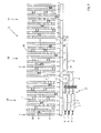
- FIG. 1 schematically shows in top plan view a possible system 1 according to the invention.
- the system 1 comprises a plurality of racks 2 extending parallel to each other, which racks each comprise a number of tray storage positions 3 disposed above and beside each other.
- trays carrying a single layer of identical products can be temporarily stored. Said products are thus presented for being collected from various tray storage positions in accordance with corresponding orders.
- said identical products are provided on a tray in a single layer (see also figure 2 ), so that the removal of one product or a number of products from the tray, which may take place in a tray storage position but also outside a tray storage position if a loaded tray is to that end temporarily removed from said tray storage position, can be done in an automated manner.
- a single layer of identical products may also be made up of a single (horizontal) row of identical products.
- trays 4 which each have a number of parallel, horizontal upright edges.
- the products are supported on the upper sides of said edges, whilst the space between the edges is available for reaching therebetween with spoons or the like, which thus gain access to the underside of (number of) product(s) present on a tray 4 for subsequently lifting the product and removing it from the tray 4.
- Such a tray and the manner in which it can be used is described, for example, in Dutch patent applications NL 1036522 and NL 1037378 .
- the system 1 comprises three transfer devices 5.
- the transfer devices 5 which will be referred to below as "depalletizer”
- pallets each carrying a number of layers of stacked, identical products are supplied, possibly from a pallet warehouse, as indicated by arrows 6.
- the depalletizers 5 which are known to the skilled person and which are also mentioned in International patent application WO 2008/089980 A1 , for example, in which they are indicated at 16, remove products from a pallet and place said products on a tray, in such a manner that the products are provided on the tray in a single layer.
- the system comprises a tray conveying system.
- Said tray conveying system comprises three distribution conveyor subsystems, which are each capable of conveying trays, which may or may not be loaded, along a conveying path.
- said conveying path extends along the short ends of a group 28 of eight racks.
- Each distribution conveyor subsystem comprises a buffer conveyor system 7, which is essentially made up of four rectilinear conveyors, which are indicated at 7a, 7b, 7c, 7d for the middle buffer conveyor system 7 in figure 1 .
- the successive conveyors 7a-7d which jointly define the shape of an elongate rectangle, join each other at right angles, defining an endless sub-conveying path. At the four corner points of the endless conveying path, transfer of a tray from a conveyor 7a-7d to a next conveyor 7a-7d takes place.
- the conveyors 7a-7d are of the roller conveyor type or of the chain conveyor type, for example.
- each distribution conveyor subsystem further comprises a supply conveyor 8, which supply conveyors 8 each extend from an associated depalletizer 5 and which connect to one of the three buffer conveyor system 7, more specifically to the conveyor 7a thereof.
- a tray lift 9 by means of which loaded trays 4 can be supplied to a tray storage position 4 and empty trays 4 can be discharged from a tray storage position 3.
- Four tray lifts 9 are provided for each group 28, as a result of which the tray storage positions 3 of all eight racks 2 of a group 28 can be reached directly by a tray lift 9.
- the tray lifts form part of the associated distribution conveyor system.
- Two product lifts 10 are provided for each pair of racks between the pairs of adjacent racks 2 of each group 28 where no tray lifts 9 are present.
- Such product lifts 10 are capable of removing one product or a number of products from a tray 4 in a tray storage position 3 and discharge said product or products to a collecting location. This process is described in great detail in Dutch patent application NL 1037379 , for example.
- the outermost racks 2 of a group 28 of eight racks 2 cannot be reached directly by a product lift 10, but product-carrying trays 4 present in one of the two outermost racks 2 can be conveyed to an adjacent rack 2 within the same group 28 by a tray lift 9, so that the products present on the tray 4 in question can be reached yet by one of the product lifts 10.
- the number of racks 2 forming part of a group 28 is geared to the capacity of each distribution conveyor subsystem. It is important in that regard that the number of trays 4 that can be handled by a distribution conveyor subsystem per unit time is at least substantially the same as the number of trays 4 in rack positions 3 that can be fully unloaded per unit time by the product lifts 10 associated with the group 28 in question.
- the lift supply conveyors 11 and the lift discharge conveyors 12, which form part of an associated distribution conveyor subsystem, are positioned in line with the racks 2.
- the tray lifts 9 can be moved to a position beyond the length of the racks 2, between pairs of adjacent lift supply conveyors 11 and lift discharge conveyors 12, so that the two tray lifts 9 can take over a loaded tray 4 from a lift supply conveyor 11 or transfer a tray, which may or may not be empty, to a lift discharge conveyor 12 at such a position.
- bridge conveyors 13, 14 are driven in opposite directions and by means of which the transfer of trays in two directions between two adjacent buffer conveyor systems 7 can be effected.
- the bridge conveyors 13, 14 make it possible, for example, 4 loaded trays present on a buffer conveyor system 7 to be transferred to an adjacent buffer conveyor system 7 so as to be eventually supplied to a tray storage position 3 of a rack 2 associated with another group 28 of racks 2.
- discharge conveyors 29 extend parallel to the supply conveyors 8, being driven in the opposite direction, however, toward the depalletizers 5 for discharging empty trays 4 to the depalletizers 5.
- the trays 4 are made available again for being loaded by the depalletizers 5.
- the conveying path associated with each distribution conveyor subsystem extends along, successively, a supply conveyor 8, the buffer conveyor 7a (partially), the buffer conveyor 7b, the buffer conveyor 7c
- a lift supply conveyor 11 (partially), a lift supply conveyor 11, and the path which the loaded tray 4 in the tray lift 9 covers between the lift supply conveyor 11 and a tray storage position 3, and for an empty tray said conveying path extends along, successively, the path which the empty tray covers between the tray storage position 3 and the lift discharge conveyor 12, the lift discharge conveyor 12, the buffer conveyor 7c (partially), the buffer conveyor 7d, the buffer conveyor 7a (partially) and the discharge conveyor 29.
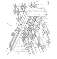
- the system 1 further comprises transfer means 15, in connection with which reference is made in particular to figure 2 .
- the transfer means 15 comprise two portals 16, each having two columns 17 and a girder 18 that extends between the upper ends of the associated columns 17.
- the girders 18 each extend over the three supply conveyors 8 and the three discharge conveyors 29, which extend parallel to each other also at the location of the transfer means 15.
- each of the supply conveyors 8 is provided with a branch 19, each branch comprising two pickup positions 20 located one behind the other.
- the pickup positions 20 are located directly below the respective girders 18 of the two portals 16.
- the trays 8 can first be discharged in a direction transversely to the main conveying direction of the associated supply conveyor 8 at the location of the branches 19 and subsequently in a direction parallel thereto to be eventually placed at one of the two pickup positions 20.
- Slides 21 are movable to and fro along the girders 18 of the portals 16 in directions perpendicular to the main conveying directions of the supply conveyors 8 and the discharge conveyors 29 extending therebelow.
- the slides 21 each carry a downwardly extending lifting cylinder 22.
- a gripping element 23 Provided on the lower end of the piston rod of the lifting cylinder is 22 is a gripping element 23, each gripping element comprising gripping arms 26, 27 which can pivot toward and away from each other about pivot axes 24, 25.
- the gripping element 23 is capable of engaging a tray 4 on two opposite sides thereof, whereupon the tray 4 can be moved upward and downward by the action of the lifting cylinders 22.
- a tray 4 that has been loaded by a particular depalletizer 5 to a tray storage position of a rack 2 associated with a group 28 of racks 2 along the short end of which the buffer conveyor system 7 to which the supply conveyor 8 that starts at the depalletizer 5 extends, but to supply said tray to a tray storage position 3 associated with another group 28.
- the transfer means 5 can be very usefully utilised for that purpose by moving the loaded tray 4 in question from one supply conveyor 8 to the (other) supply conveyor 8 that connects to the buffer conveyor system 7 associated with the group 28 in question.
- the tray in question is to that end picked up from a pickup position 20 of a supply conveyor 8 by successively engaging the tray by means of a gripping element 23, retracting the lifting cylinder 22, moving the slide 21 along the associated girder 18 to a position above the desired supply conveyor 8, and extending the lifting cylinder 22 at that location so as to subsequently release the engagement by the gripper 25 as soon as the tray is supported on the other buffer conveyor system 7. It stands to reason that space must be available on the supply conveyor 8 in order to realise this.
Landscapes
- Engineering & Computer Science (AREA)
- Mechanical Engineering (AREA)
- Warehouses Or Storage Devices (AREA)
Applications Claiming Priority (1)
| Application Number | Priority Date | Filing Date | Title |
|---|---|---|---|
| NL2004389A NL2004389C2 (nl) | 2010-03-12 | 2010-03-12 | Systeem voor het verdelen van goederen. |
Publications (3)
| Publication Number | Publication Date |
|---|---|
| EP2364933A1 true EP2364933A1 (fr) | 2011-09-14 |
| EP2364933B1 EP2364933B1 (fr) | 2012-12-05 |
| EP2364933B2 EP2364933B2 (fr) | 2015-11-11 |
Family
ID=43063544
Family Applications (1)
| Application Number | Title | Priority Date | Filing Date |
|---|---|---|---|
| EP11157152.7A Not-in-force EP2364933B2 (fr) | 2010-03-12 | 2011-03-07 | Système pour la distribution de marchandises |
Country Status (2)
| Country | Link |
|---|---|
| EP (1) | EP2364933B2 (fr) |
| NL (1) | NL2004389C2 (fr) |
Cited By (2)
| Publication number | Priority date | Publication date | Assignee | Title |
|---|---|---|---|---|
| CN110316500A (zh) * | 2019-06-21 | 2019-10-11 | 南京乐鹰商用厨房设备有限公司 | 一种米饭生产线自动储锅系统 |
| WO2021244381A1 (fr) * | 2020-06-01 | 2021-12-09 | 于君 | Système de stockage et de prise d'articles |
Families Citing this family (1)
| Publication number | Priority date | Publication date | Assignee | Title |
|---|---|---|---|---|
| US11505407B2 (en) | 2016-06-28 | 2022-11-22 | Beumer Group A/S | Storage and retrieval system |
Citations (5)
| Publication number | Priority date | Publication date | Assignee | Title |
|---|---|---|---|---|
| WO2008022767A1 (fr) * | 2006-08-21 | 2008-02-28 | SSI Schäfer Noell GmbH Lager- und Systemtechnik | Procédé et dispositif pour décharger des plateaux chargés de couches de palettes |
| WO2008089980A1 (fr) | 2007-01-24 | 2008-07-31 | SSI Schäfer Noell GmbH Lager- und Systemtechnik | Système de préparation de commande comprenant une unité de transport de rayonnages et procédé d'utilisation d'un tel système |
| NL1036522C2 (nl) | 2009-02-06 | 2010-08-09 | Vanderlande Ind Nederland | Systeem en werkwijze voor het verzamelen van verschillende producten op een verzamelpallet. |
| NL1037378C2 (nl) | 2009-02-06 | 2010-08-09 | Vanderlande Ind Bv | Werkwijze voor het verzamelen van een aantal verschillende, tot een opdracht behorende, producten, stellingsbedienapparaat voor toepassing in een dergelijke werkwijze en systeem voor het verzamelen van verschillende producten op een verzamelpallet. |
| NL1037379C2 (nl) | 2009-10-09 | 2011-04-12 | Vanderlande Ind Bv | Systeem voor het in een gewenste volgorde verzamelen van verschillende, tot een opdracht behorende, producten. |
-
2010
- 2010-03-12 NL NL2004389A patent/NL2004389C2/nl not_active IP Right Cessation
-
2011
- 2011-03-07 EP EP11157152.7A patent/EP2364933B2/fr not_active Not-in-force
Patent Citations (5)
| Publication number | Priority date | Publication date | Assignee | Title |
|---|---|---|---|---|
| WO2008022767A1 (fr) * | 2006-08-21 | 2008-02-28 | SSI Schäfer Noell GmbH Lager- und Systemtechnik | Procédé et dispositif pour décharger des plateaux chargés de couches de palettes |
| WO2008089980A1 (fr) | 2007-01-24 | 2008-07-31 | SSI Schäfer Noell GmbH Lager- und Systemtechnik | Système de préparation de commande comprenant une unité de transport de rayonnages et procédé d'utilisation d'un tel système |
| NL1036522C2 (nl) | 2009-02-06 | 2010-08-09 | Vanderlande Ind Nederland | Systeem en werkwijze voor het verzamelen van verschillende producten op een verzamelpallet. |
| NL1037378C2 (nl) | 2009-02-06 | 2010-08-09 | Vanderlande Ind Bv | Werkwijze voor het verzamelen van een aantal verschillende, tot een opdracht behorende, producten, stellingsbedienapparaat voor toepassing in een dergelijke werkwijze en systeem voor het verzamelen van verschillende producten op een verzamelpallet. |
| NL1037379C2 (nl) | 2009-10-09 | 2011-04-12 | Vanderlande Ind Bv | Systeem voor het in een gewenste volgorde verzamelen van verschillende, tot een opdracht behorende, producten. |
Cited By (3)
| Publication number | Priority date | Publication date | Assignee | Title |
|---|---|---|---|---|
| CN110316500A (zh) * | 2019-06-21 | 2019-10-11 | 南京乐鹰商用厨房设备有限公司 | 一种米饭生产线自动储锅系统 |
| CN110316500B (zh) * | 2019-06-21 | 2020-12-29 | 南京乐鹰商用厨房设备有限公司 | 一种米饭生产线自动储锅系统 |
| WO2021244381A1 (fr) * | 2020-06-01 | 2021-12-09 | 于君 | Système de stockage et de prise d'articles |
Also Published As
| Publication number | Publication date |
|---|---|
| EP2364933B1 (fr) | 2012-12-05 |
| NL2004389C2 (nl) | 2011-09-13 |
| EP2364933B2 (fr) | 2015-11-11 |
Similar Documents
| Publication | Publication Date | Title |
|---|---|---|
| CN108146948B (zh) | 用于存入和取出物体的方法以及用于执行该方法的仓储系统 | |
| EP2923971B1 (fr) | Système de collection de produits et son procédé d'utilisation | |
| US7097045B2 (en) | Automated system and method of storing and picking articles | |
| AU2012257735B2 (en) | Method for storing and/or order-picking product units | |
| EP3282829B1 (fr) | Dispositif et procédé de manipulation de conteneur robotique | |
| US6321138B1 (en) | Storage and retrieval system with automated order make up | |
| JP6435463B2 (ja) | 保管設備からの運搬ユニットを提供するための方法 | |
| US8494673B2 (en) | Warehouse system and method for operating the same | |
| EP2436619A2 (fr) | Système convoyeur vertical | |
| CN115151495B (zh) | 输送机系统 | |
| US20060245858A1 (en) | Apparatus for forming a sequence of load carriers by means of a temporary store, and method for temporary storage | |
| EP2485970B1 (fr) | Système de collecte de différents produits d'une commande dans un ordre souhaité | |
| US8342792B2 (en) | Article separation directly on storage and retrieval device | |
| WO2010090516A1 (fr) | Système de collecte de différents produits sur une palette de capture | |
| EP2655221B1 (fr) | Système et procédé pour faire transiter des bagages | |
| US20120097064A1 (en) | Method and loading system for order-picking articles onto destination load carriers | |
| WO2020066885A1 (fr) | Système de collecte et de tri | |
| US20200048017A1 (en) | Method for automatically stacking packages in layers on a support | |
| JP2006103873A (ja) | 仕分け設備 | |
| EP2364933B2 (fr) | Système pour la distribution de marchandises | |
| CN216425639U (zh) | 货物输送系统 | |
| US20230331475A1 (en) | Method for operating a storage facility without lifts | |
| EP2733090B1 (fr) | Procédé de chargement de produits d'un magasin sur un support | |
| CA3188754A1 (fr) | Systemes de chargement et de dechargement de supports mobiles de collecte sur un robot autonome mobile pour la preparation de commande | |
| CN211687205U (zh) | 用于处理物品组和/或物品层的设备 |
Legal Events
| Date | Code | Title | Description |
|---|---|---|---|
| PUAI | Public reference made under article 153(3) epc to a published international application that has entered the european phase |
Free format text: ORIGINAL CODE: 0009012 |
|
| AK | Designated contracting states |
Kind code of ref document: A1 Designated state(s): AL AT BE BG CH CY CZ DE DK EE ES FI FR GB GR HR HU IE IS IT LI LT LU LV MC MK MT NL NO PL PT RO RS SE SI SK SM TR |
|
| AX | Request for extension of the european patent |
Extension state: BA ME |
|
| 17P | Request for examination filed |
Effective date: 20120313 |
|
| GRAP | Despatch of communication of intention to grant a patent |
Free format text: ORIGINAL CODE: EPIDOSNIGR1 |
|
| RIC1 | Information provided on ipc code assigned before grant |
Ipc: B65G 1/04 20060101AFI20120518BHEP |
|
| GRAS | Grant fee paid |
Free format text: ORIGINAL CODE: EPIDOSNIGR3 |
|
| GRAA | (expected) grant |
Free format text: ORIGINAL CODE: 0009210 |
|
| AK | Designated contracting states |
Kind code of ref document: B1 Designated state(s): AL AT BE BG CH CY CZ DE DK EE ES FI FR GB GR HR HU IE IS IT LI LT LU LV MC MK MT NL NO PL PT RO RS SE SI SK SM TR |
|
| REG | Reference to a national code |
Ref country code: GB Ref legal event code: FG4D |
|
| REG | Reference to a national code |
Ref country code: CH Ref legal event code: EP |
|
| REG | Reference to a national code |
Ref country code: AT Ref legal event code: REF Ref document number: 587162 Country of ref document: AT Kind code of ref document: T Effective date: 20121215 |
|
| REG | Reference to a national code |
Ref country code: IE Ref legal event code: FG4D |
|
| REG | Reference to a national code |
Ref country code: DE Ref legal event code: R096 Ref document number: 602011000533 Country of ref document: DE Effective date: 20130131 |
|
| REG | Reference to a national code |
Ref country code: NL Ref legal event code: T3 |
|
| REG | Reference to a national code |
Ref country code: AT Ref legal event code: MK05 Ref document number: 587162 Country of ref document: AT Kind code of ref document: T Effective date: 20121205 |
|
| PG25 | Lapsed in a contracting state [announced via postgrant information from national office to epo] |
Ref country code: SE Free format text: LAPSE BECAUSE OF FAILURE TO SUBMIT A TRANSLATION OF THE DESCRIPTION OR TO PAY THE FEE WITHIN THE PRESCRIBED TIME-LIMIT Effective date: 20121205 Ref country code: HR Free format text: LAPSE BECAUSE OF FAILURE TO SUBMIT A TRANSLATION OF THE DESCRIPTION OR TO PAY THE FEE WITHIN THE PRESCRIBED TIME-LIMIT Effective date: 20121205 Ref country code: ES Free format text: LAPSE BECAUSE OF FAILURE TO SUBMIT A TRANSLATION OF THE DESCRIPTION OR TO PAY THE FEE WITHIN THE PRESCRIBED TIME-LIMIT Effective date: 20130316 Ref country code: NO Free format text: LAPSE BECAUSE OF FAILURE TO SUBMIT A TRANSLATION OF THE DESCRIPTION OR TO PAY THE FEE WITHIN THE PRESCRIBED TIME-LIMIT Effective date: 20130305 Ref country code: LT Free format text: LAPSE BECAUSE OF FAILURE TO SUBMIT A TRANSLATION OF THE DESCRIPTION OR TO PAY THE FEE WITHIN THE PRESCRIBED TIME-LIMIT Effective date: 20121205 Ref country code: FI Free format text: LAPSE BECAUSE OF FAILURE TO SUBMIT A TRANSLATION OF THE DESCRIPTION OR TO PAY THE FEE WITHIN THE PRESCRIBED TIME-LIMIT Effective date: 20121205 |
|
| REG | Reference to a national code |
Ref country code: LT Ref legal event code: MG4D |
|
| PG25 | Lapsed in a contracting state [announced via postgrant information from national office to epo] |
Ref country code: GR Free format text: LAPSE BECAUSE OF FAILURE TO SUBMIT A TRANSLATION OF THE DESCRIPTION OR TO PAY THE FEE WITHIN THE PRESCRIBED TIME-LIMIT Effective date: 20130306 Ref country code: PL Free format text: LAPSE BECAUSE OF FAILURE TO SUBMIT A TRANSLATION OF THE DESCRIPTION OR TO PAY THE FEE WITHIN THE PRESCRIBED TIME-LIMIT Effective date: 20121205 Ref country code: SI Free format text: LAPSE BECAUSE OF FAILURE TO SUBMIT A TRANSLATION OF THE DESCRIPTION OR TO PAY THE FEE WITHIN THE PRESCRIBED TIME-LIMIT Effective date: 20121205 Ref country code: LV Free format text: LAPSE BECAUSE OF FAILURE TO SUBMIT A TRANSLATION OF THE DESCRIPTION OR TO PAY THE FEE WITHIN THE PRESCRIBED TIME-LIMIT Effective date: 20121205 |
|
| PG25 | Lapsed in a contracting state [announced via postgrant information from national office to epo] |
Ref country code: AT Free format text: LAPSE BECAUSE OF FAILURE TO SUBMIT A TRANSLATION OF THE DESCRIPTION OR TO PAY THE FEE WITHIN THE PRESCRIBED TIME-LIMIT Effective date: 20121205 |
|
| PG25 | Lapsed in a contracting state [announced via postgrant information from national office to epo] |
Ref country code: RS Free format text: LAPSE BECAUSE OF FAILURE TO SUBMIT A TRANSLATION OF THE DESCRIPTION OR TO PAY THE FEE WITHIN THE PRESCRIBED TIME-LIMIT Effective date: 20121205 Ref country code: SK Free format text: LAPSE BECAUSE OF FAILURE TO SUBMIT A TRANSLATION OF THE DESCRIPTION OR TO PAY THE FEE WITHIN THE PRESCRIBED TIME-LIMIT Effective date: 20121205 Ref country code: BE Free format text: LAPSE BECAUSE OF FAILURE TO SUBMIT A TRANSLATION OF THE DESCRIPTION OR TO PAY THE FEE WITHIN THE PRESCRIBED TIME-LIMIT Effective date: 20121205 Ref country code: IS Free format text: LAPSE BECAUSE OF FAILURE TO SUBMIT A TRANSLATION OF THE DESCRIPTION OR TO PAY THE FEE WITHIN THE PRESCRIBED TIME-LIMIT Effective date: 20130405 Ref country code: CZ Free format text: LAPSE BECAUSE OF FAILURE TO SUBMIT A TRANSLATION OF THE DESCRIPTION OR TO PAY THE FEE WITHIN THE PRESCRIBED TIME-LIMIT Effective date: 20121205 Ref country code: BG Free format text: LAPSE BECAUSE OF FAILURE TO SUBMIT A TRANSLATION OF THE DESCRIPTION OR TO PAY THE FEE WITHIN THE PRESCRIBED TIME-LIMIT Effective date: 20130305 Ref country code: EE Free format text: LAPSE BECAUSE OF FAILURE TO SUBMIT A TRANSLATION OF THE DESCRIPTION OR TO PAY THE FEE WITHIN THE PRESCRIBED TIME-LIMIT Effective date: 20121205 |
|
| PLBI | Opposition filed |
Free format text: ORIGINAL CODE: 0009260 |
|
| PG25 | Lapsed in a contracting state [announced via postgrant information from national office to epo] |
Ref country code: PT Free format text: LAPSE BECAUSE OF FAILURE TO SUBMIT A TRANSLATION OF THE DESCRIPTION OR TO PAY THE FEE WITHIN THE PRESCRIBED TIME-LIMIT Effective date: 20130405 Ref country code: RO Free format text: LAPSE BECAUSE OF FAILURE TO SUBMIT A TRANSLATION OF THE DESCRIPTION OR TO PAY THE FEE WITHIN THE PRESCRIBED TIME-LIMIT Effective date: 20121205 |
|
| 26 | Opposition filed |
Opponent name: SSI SCHAEFER NOELL GMBH LAGER- UND SYSTEMTECHNIK Effective date: 20130816 |
|
| PLAX | Notice of opposition and request to file observation + time limit sent |
Free format text: ORIGINAL CODE: EPIDOSNOBS2 |
|
| PG25 | Lapsed in a contracting state [announced via postgrant information from national office to epo] |
Ref country code: MC Free format text: LAPSE BECAUSE OF NON-PAYMENT OF DUE FEES Effective date: 20130331 Ref country code: DK Free format text: LAPSE BECAUSE OF FAILURE TO SUBMIT A TRANSLATION OF THE DESCRIPTION OR TO PAY THE FEE WITHIN THE PRESCRIBED TIME-LIMIT Effective date: 20121205 |
|
| REG | Reference to a national code |
Ref country code: DE Ref legal event code: R026 Ref document number: 602011000533 Country of ref document: DE Effective date: 20130816 |
|
| PG25 | Lapsed in a contracting state [announced via postgrant information from national office to epo] |
Ref country code: CY Free format text: LAPSE BECAUSE OF FAILURE TO SUBMIT A TRANSLATION OF THE DESCRIPTION OR TO PAY THE FEE WITHIN THE PRESCRIBED TIME-LIMIT Effective date: 20121205 |
|
| PG25 | Lapsed in a contracting state [announced via postgrant information from national office to epo] |
Ref country code: IT Free format text: LAPSE BECAUSE OF FAILURE TO SUBMIT A TRANSLATION OF THE DESCRIPTION OR TO PAY THE FEE WITHIN THE PRESCRIBED TIME-LIMIT Effective date: 20121205 |
|
| REG | Reference to a national code |
Ref country code: IE Ref legal event code: MM4A |
|
| PG25 | Lapsed in a contracting state [announced via postgrant information from national office to epo] |
Ref country code: AL Free format text: LAPSE BECAUSE OF FAILURE TO SUBMIT A TRANSLATION OF THE DESCRIPTION OR TO PAY THE FEE WITHIN THE PRESCRIBED TIME-LIMIT Effective date: 20121205 Ref country code: IE Free format text: LAPSE BECAUSE OF NON-PAYMENT OF DUE FEES Effective date: 20130307 |
|
| PLAF | Information modified related to communication of a notice of opposition and request to file observations + time limit |
Free format text: ORIGINAL CODE: EPIDOSCOBS2 |
|
| PLBB | Reply of patent proprietor to notice(s) of opposition received |
Free format text: ORIGINAL CODE: EPIDOSNOBS3 |
|
| PG25 | Lapsed in a contracting state [announced via postgrant information from national office to epo] |
Ref country code: MT Free format text: LAPSE BECAUSE OF FAILURE TO SUBMIT A TRANSLATION OF THE DESCRIPTION OR TO PAY THE FEE WITHIN THE PRESCRIBED TIME-LIMIT Effective date: 20121205 |
|
| REG | Reference to a national code |
Ref country code: CH Ref legal event code: PL |
|
| PG25 | Lapsed in a contracting state [announced via postgrant information from national office to epo] |
Ref country code: CH Free format text: LAPSE BECAUSE OF NON-PAYMENT OF DUE FEES Effective date: 20140331 Ref country code: LI Free format text: LAPSE BECAUSE OF NON-PAYMENT OF DUE FEES Effective date: 20140331 |
|
| REG | Reference to a national code |
Ref country code: FR Ref legal event code: PLFP Year of fee payment: 5 |
|
| PG25 | Lapsed in a contracting state [announced via postgrant information from national office to epo] |
Ref country code: SM Free format text: LAPSE BECAUSE OF FAILURE TO SUBMIT A TRANSLATION OF THE DESCRIPTION OR TO PAY THE FEE WITHIN THE PRESCRIBED TIME-LIMIT Effective date: 20121205 |
|
| PLAB | Opposition data, opponent's data or that of the opponent's representative modified |
Free format text: ORIGINAL CODE: 0009299OPPO |
|
| PG25 | Lapsed in a contracting state [announced via postgrant information from national office to epo] |
Ref country code: TR Free format text: LAPSE BECAUSE OF FAILURE TO SUBMIT A TRANSLATION OF THE DESCRIPTION OR TO PAY THE FEE WITHIN THE PRESCRIBED TIME-LIMIT Effective date: 20121205 |
|
| R26 | Opposition filed (corrected) |
Opponent name: SSI SCHAEFER NOELL GMBH LAGER- UND SYSTEMTECHNIK Effective date: 20130816 |
|
| PG25 | Lapsed in a contracting state [announced via postgrant information from national office to epo] |
Ref country code: MK Free format text: LAPSE BECAUSE OF FAILURE TO SUBMIT A TRANSLATION OF THE DESCRIPTION OR TO PAY THE FEE WITHIN THE PRESCRIBED TIME-LIMIT Effective date: 20121205 Ref country code: LU Free format text: LAPSE BECAUSE OF NON-PAYMENT OF DUE FEES Effective date: 20130307 Ref country code: HU Free format text: LAPSE BECAUSE OF FAILURE TO SUBMIT A TRANSLATION OF THE DESCRIPTION OR TO PAY THE FEE WITHIN THE PRESCRIBED TIME-LIMIT; INVALID AB INITIO Effective date: 20110307 |
|
| PUAH | Patent maintained in amended form |
Free format text: ORIGINAL CODE: 0009272 |
|
| STAA | Information on the status of an ep patent application or granted ep patent |
Free format text: STATUS: PATENT MAINTAINED AS AMENDED |
|
| 27A | Patent maintained in amended form |
Effective date: 20151111 |
|
| AK | Designated contracting states |
Kind code of ref document: B2 Designated state(s): AL AT BE BG CH CY CZ DE DK EE ES FI FR GB GR HR HU IE IS IT LI LT LU LV MC MK MT NL NO PL PT RO RS SE SI SK SM TR |
|
| REG | Reference to a national code |
Ref country code: DE Ref legal event code: R102 Ref document number: 602011000533 Country of ref document: DE |
|
| REG | Reference to a national code |
Ref country code: FR Ref legal event code: PLFP Year of fee payment: 6 |
|
| REG | Reference to a national code |
Ref country code: NL Ref legal event code: FP |
|
| REG | Reference to a national code |
Ref country code: FR Ref legal event code: PLFP Year of fee payment: 7 |
|
| PGFP | Annual fee paid to national office [announced via postgrant information from national office to epo] |
Ref country code: DE Payment date: 20170322 Year of fee payment: 7 Ref country code: FR Payment date: 20170322 Year of fee payment: 7 Ref country code: NL Payment date: 20170321 Year of fee payment: 7 |
|
| PGFP | Annual fee paid to national office [announced via postgrant information from national office to epo] |
Ref country code: GB Payment date: 20170322 Year of fee payment: 7 |
|
| REG | Reference to a national code |
Ref country code: DE Ref legal event code: R119 Ref document number: 602011000533 Country of ref document: DE |
|
| REG | Reference to a national code |
Ref country code: NL Ref legal event code: MM Effective date: 20180401 |
|
| GBPC | Gb: european patent ceased through non-payment of renewal fee |
Effective date: 20180307 |
|
| PG25 | Lapsed in a contracting state [announced via postgrant information from national office to epo] |
Ref country code: NL Free format text: LAPSE BECAUSE OF NON-PAYMENT OF DUE FEES Effective date: 20180401 |
|
| PG25 | Lapsed in a contracting state [announced via postgrant information from national office to epo] |
Ref country code: DE Free format text: LAPSE BECAUSE OF NON-PAYMENT OF DUE FEES Effective date: 20181002 |
|
| PG25 | Lapsed in a contracting state [announced via postgrant information from national office to epo] |
Ref country code: GB Free format text: LAPSE BECAUSE OF NON-PAYMENT OF DUE FEES Effective date: 20180307 |
|
| PG25 | Lapsed in a contracting state [announced via postgrant information from national office to epo] |
Ref country code: FR Free format text: LAPSE BECAUSE OF NON-PAYMENT OF DUE FEES Effective date: 20180331 |