EP2364771A1 - Applikatorsystem und Verfahren zu seiner Verwendung - Google Patents
Applikatorsystem und Verfahren zu seiner Verwendung Download PDFInfo
- Publication number
- EP2364771A1 EP2364771A1 EP11002627A EP11002627A EP2364771A1 EP 2364771 A1 EP2364771 A1 EP 2364771A1 EP 11002627 A EP11002627 A EP 11002627A EP 11002627 A EP11002627 A EP 11002627A EP 2364771 A1 EP2364771 A1 EP 2364771A1
- Authority
- EP
- European Patent Office
- Prior art keywords
- solution
- assembly
- applicator
- sources
- homogenizing
- Prior art date
- Legal status (The legal status is an assumption and is not a legal conclusion. Google has not performed a legal analysis and makes no representation as to the accuracy of the status listed.)
- Withdrawn
Links
Images


Classifications
-
- B—PERFORMING OPERATIONS; TRANSPORTING
- B01—PHYSICAL OR CHEMICAL PROCESSES OR APPARATUS IN GENERAL
- B01F—MIXING, e.g. DISSOLVING, EMULSIFYING OR DISPERSING
- B01F27/00—Mixers with rotary stirring devices in fixed receptacles; Kneaders
- B01F27/27—Mixers with stator-rotor systems, e.g. with intermeshing teeth or cylinders or having orifices
-
- B—PERFORMING OPERATIONS; TRANSPORTING
- B01—PHYSICAL OR CHEMICAL PROCESSES OR APPARATUS IN GENERAL
- B01F—MIXING, e.g. DISSOLVING, EMULSIFYING OR DISPERSING
- B01F27/00—Mixers with rotary stirring devices in fixed receptacles; Kneaders
- B01F27/50—Pipe mixers, i.e. mixers wherein the materials to be mixed flow continuously through pipes, e.g. column mixers
-
- B—PERFORMING OPERATIONS; TRANSPORTING
- B01—PHYSICAL OR CHEMICAL PROCESSES OR APPARATUS IN GENERAL
- B01F—MIXING, e.g. DISSOLVING, EMULSIFYING OR DISPERSING
- B01F33/00—Other mixers; Mixing plants; Combinations of mixers
- B01F33/50—Movable or transportable mixing devices or plants
- B01F33/501—Movable mixing devices, i.e. readily shifted or displaced from one place to another, e.g. portable during use
- B01F33/5011—Movable mixing devices, i.e. readily shifted or displaced from one place to another, e.g. portable during use portable during use, e.g. hand-held
-
- B—PERFORMING OPERATIONS; TRANSPORTING
- B01—PHYSICAL OR CHEMICAL PROCESSES OR APPARATUS IN GENERAL
- B01F—MIXING, e.g. DISSOLVING, EMULSIFYING OR DISPERSING
- B01F35/00—Accessories for mixers; Auxiliary operations or auxiliary devices; Parts or details of general application
- B01F35/80—Forming a predetermined ratio of the substances to be mixed
- B01F35/88—Forming a predetermined ratio of the substances to be mixed by feeding the materials batchwise
- B01F35/882—Forming a predetermined ratio of the substances to be mixed by feeding the materials batchwise using measuring chambers, e.g. volumetric pumps, for feeding the substances
- B01F35/8822—Forming a predetermined ratio of the substances to be mixed by feeding the materials batchwise using measuring chambers, e.g. volumetric pumps, for feeding the substances using measuring chambers of the piston or plunger type
-
- B—PERFORMING OPERATIONS; TRANSPORTING
- B01—PHYSICAL OR CHEMICAL PROCESSES OR APPARATUS IN GENERAL
- B01F—MIXING, e.g. DISSOLVING, EMULSIFYING OR DISPERSING
- B01F2101/00—Mixing characterised by the nature of the mixed materials or by the application field
- B01F2101/2202—Mixing compositions or mixers in the medical or veterinary field
-
- B—PERFORMING OPERATIONS; TRANSPORTING
- B01—PHYSICAL OR CHEMICAL PROCESSES OR APPARATUS IN GENERAL
- B01F—MIXING, e.g. DISSOLVING, EMULSIFYING OR DISPERSING
- B01F2101/00—Mixing characterised by the nature of the mixed materials or by the application field
- B01F2101/2305—Mixers of the two-component package type, i.e. where at least two components are separately stored, and are mixed in the moment of application
-
- B—PERFORMING OPERATIONS; TRANSPORTING
- B05—SPRAYING OR ATOMISING IN GENERAL; APPLYING FLUENT MATERIALS TO SURFACES, IN GENERAL
- B05D—PROCESSES FOR APPLYING FLUENT MATERIALS TO SURFACES, IN GENERAL
- B05D1/00—Processes for applying liquids or other fluent materials
- B05D1/34—Applying different liquids or other fluent materials simultaneously
Definitions
- the present disclosure relates to applicators, applicator systems, and the like, for mixing, homogenizing and/or emulsifying two or more solutions and/or substances prior to application, and more particularly, to an applicator system for emulsifying a polyurethane based adhesive/sealant and water prior to application.
- Bioadhesives are known in the art, as are various methods for applying the bioadhesive. Bioadhesives offer many significant advantages over conventional wound closure methods, i.e., using sutures, staples, clips or other suitable mechanical fasteners. Bioadhesives are faster and simpler to apply, have a tendency to promote quicker wound closure with less scaring, and eliminate the need for a follow up visit to remove the mechanical fasteners.
- bioadhesives are composed of components that have a tendency to immediately activate and in some instances, rapidly polymerize when combined with one another. Because of this immediate activation and/or rapid polymerization of the bioadhesive, the components comprising the bioadhesive may not be combined until immediately prior to application.
- Conventional applicators for mixing the bioadhesive components prior to application generally include a mixing chamber or common conduit where the solutions are combined, i.e., mixed, as the solutions pass therethrough. The consistency of this mixture may vary depending on the types of solutions being combined, their quantities, and the speed at which the solutions pass through the mixing chamber.
- the components In an application requiring a homogenized solution, the components must be mixed separate from the applicator using a stand-alone or portable homogenizer, thus ensuring proper mixing.
- a surgeon When preparing the homogenized solution for application a surgeon is limited to mixing small amounts because once the solutions are combined, it may begin to harden. Any hardening prior to application may cause the applicator tip to clog and prevent an even application of the solution.
- U.S. Patent No 3,767,085 to Cannon et al . discloses such a device.
- the '085 patent discloses a double barrel carpule type syringe for the mixing of an elastomeric base material and an accelerator.
- the mixing syringe includes, on a distal end thereof, a common mixing and dispensing chamber provided with a rotary agitator driven from a motor on the syringe.
- the mixing syringe further includes a double plunger through which manual depression thereof results in the discharge of the fluids into the mixing and dispensing chamber.
- an applicator system capable of mixing, homogenizing and/or emulsifying two or more solutions prior to application.
- a system for homogenizing two or more solutions includes at least a first and a second source of solution, a hand held homogenizer having a homogenizing assembly, and an applicator assembly.
- the applicator assembly is configured to fluidly communicate the at least first and second sources of solution with the homogenizing assembly, wherein solution from each of the at least first and second source of solution is mixed by the homogenizing assembly upon dispensing of the solution from the first and second sources of solution
- the first and second sources of solution may comprise syringes or metering pumps.
- the applicator assembly may be integrally formed with the homogenizer.
- the homogenizer may be configured to rotate the homogenizer assembly at about 1,000 to about 35,000 RPM, preferably 1,000 to 25,000 RPM.
- the applicator assembly may further be configured to include an outlet for dispensing a homogenized solution.
- the outlet may form an applicator tip for applying the homogenized solution.
- the outlet may instead form a connection for releasably securing a hose or tube.
- the homogenizing assembly may include rotors and stators.
- the homogenizing assembly may be integrally formed with the applicator assembly.
- the homogenizing assembly may also be disposable.
- the applicator system may further include an activation mechanism for automatically supplying the solution from the first and second sources of solution.
- the activation mechanism may include a button or switch mounted on the applicator assembly.
- an applicator assembly for mixing two or more solutions.
- the applicator assembly includes a housing defining at least two inlets and a mixing chamber, wherein each of the inlets are configured to releasably engage a respective one of the two or more sources of solution.
- the inlets are in fluid communication with the mixing chamber.
- the applicator assembly further includes a mixing assembly rotatably mounted within the mixing chamber.
- the mixing assembly may be configured to operably connect to a motor, wherein a solution from each of the two or more sources of solution are mixed with one another by the mixing assembly as the solutions pass through the mixing chamber.
- the housing further defines an outlet.
- the mixing assembly may be integrally formed with the motor.
- the two or more sources of solution are syringes or metering pumps.
- the mixing assembly may be disposable.
- the applicator assembly may further include an activation mechanism for selectively releasing the solutions from the two or more sources of solution.
- the activation mechanism may inlude a dial for selectively activating the applicator assembly.
- the activation mechanism may include a motor.
- Yet another aspect of this disclosure provides a method for mixing and applying two or more solutions.
- the method includes the steps of providing an applicator assembly having a housing configured for receiving two or more sources of solution, and a hand held homogenizer having a homogenizing assembly operably connected to the housing, wherein said housing is further configured to fluidly communicate each of said two or more sources of solution with said homogenizing assembly.
- the method further including the steps of providing two or more sources of solution, operably connecting said two or more sources of solution with said applicator assembly, dispensing solution from each of said two or more sources of solution into said housing, and activating said homogenizing assembly.
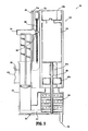
- FIG. 1 is a front, elevational view of the applicator system according to an embodiment of the present disclosure
- FIG. 2 is a side, elevational view of an applicator assembly and a first container of the applicator system of FIG. 2 ;
- FIG. 3 is a partial, cross-sectional, front, elevational view of the applicator assembly of the applicator system of FIGS. 1 and 2 ;
- FIG. 4 is a front, elevational view of an alternate embodiment of an applicator system according to the present disclosure.
- FIG. 5 is a partial, side, elevational view of an applicator and a first container of solution of the applicator system of FIG. 4 ;
- FIG. 6 is a partial, cross-sectional, front, elevational view of the applicator system of FIGS. 4 and 5 ;
- FIG. 7 is a side, elevational view of another embodiment of the applicator system of the present disclosure.
- FIG. 8 is a front, elevational view of the applicator system of FIG. 7 ;
- FIG. 9 is a partial, longitudinal, cross-sectional side, elevational view of the applicator system of FIGS. 7 and 8 .
- the present disclosure relates specifically to the emulsification and/or homogenization of a polymer adhesive and water
- aspects of the present disclosure can be incorporated into any apparatus, system or method where two or more solutions require mixing, homogenization, emulsification, or the like, prior to application.
- Embodiments of the presently disclosed applicator will now be described in detail with reference to the drawings in which like reference numerals designate identical or corresponding elements in each of the several views.
- distal refers to that portion of the instrument, or component thereof which is further from the user while the term “proximal” refers to that portion which is closer to the user.
- Applicator system 10 includes a hand-held homogenizer 50, an applicator assembly 100 and two containers 60, 70 for selectively dispensing solution, e.g. syringes.
- applicator assembly 100 includes a housing 110, an arm 112 extending from housing 110, and a mount 114 fixedly attached to a distal end of arm 112.
- Mount 114 is configured to define openings 114a, 114b for selectively receiving respective syringes 60, 70 therein. Openings 114a, 114b may be configured to accommodate any number of solution containing vessels or sources, including, but not limited to, syringes, bottles, tubes and hoses.
- Mount 114 may be slideably supported within a longitudinal groove 112a defined in arm 112. In this manner, mount 114 may be selectively positioned along extension arm 112 as indicated by arrow "A".
- the spacing or distance between housing 110 and mount 114 may be adjusted to accommodate syringes or other vessels of varying dimensions.
- housing 110 includes first and second inlets 120, 122, respectively, an entrance conduit 124 fluidly interconnecting first and second inlets 120, 122, a mixing chamber 126 fluidly connected to entrance conduit 124, an exit conduit 128 fluidly connected to mixing chamber 126, and an outlet 130 fluidly connected to exit conduit 128.
- Housing 110 defines an opening 134 formed therein that is configured for selectively engaging and receiving a mixing assembly 56 of homogenizer 50.
- Inlets 120, 122 fluidly communicate with mixing chamber 126 via entrance conduit 124.
- Outlet 130 may be configured, as shown in FIGS. 1-3 , as a needle 132 for directly applying or dispensing of the homogenized solution to a target site. Outlet 130 may instead be configured for operable fluid engagement with a conduit, hose, tube or the like, for remotely applying the homogenized solution.
- Inlets 120, 122 of housing 110 may be configured for selective engagement with syringes 60, 70, respectively.
- Each inlet 120, 122 may include a threaded portion 120a, 122a for selectively receiving syringes 60, 70.
- Homogenizer 50 may be any known, commercially available portable homogenizer. Homogenizer 50 may operate at a single speed or may be capable of operating at variable speeds. Homogenizer 50 is preferably configured to operate in the range of about 1,000 to about 35,000 RPM, preferable 1,000-25000 RPM. Homogenizer 50 may be battery operated.
- homogenizer 50 includes a handle 52 housing a drive means, such as a motor 58, a drive shaft 54 extending from drive means 58, and a mixing assembly 56 supported on a distal end of shaft 54.
- Mixing assembly 56 comprises rotors 56a and stators 56b.
- Rotors 56a and stators 56b may be made from stainless steel, polymers or the like.
- Mixing assembly 56 may include any number of rotors 56a and stators 56b in any configuration. Rotors 56a and stators 56b may be disposable, replaceable and/or sterilizable.
- Mixing assembly 56 of homogenizer 50 is rotatably mounted in mixing chamber 126 to homogenize the solutions introduced from syringes 60, 70.
- Homogenizer 50 may include a lever, button or other suitable activation switch 52a for activating homogenizing assembly 56.
- syringes 60, 70 are inserted through openings 14a, 114b of mount 114 and engageably coupled in threaded portions 120a, 122a of inlets 120, 122, respectively.
- homogenizer 50 may be activated. Depression of respective plungers 62, 72 of syringes 60, 70 causes the individual solutions contained within each syringe 60, 70 to be expelled into inlets 120, 122, respectively, and received within or advanced into entrance conduit 124.
- the individual solutions from syringes 60, 70 are first combined in entrance conduit 124 to form a solution mix before being introduced or advanced into mixing chamber 126.
- mixing assembly 56 causes the further mixing, homogenization, emulsification or the like, of the solution mix to form a homogenized solution.
- the resulting homogenized solution is further advanced through mixing chamber 126 and through exit conduit 128 before being forced out through outlet 130.
- the independent configuration of syringes 60,70 permit a user to adjusted the amount of solution expelled from each syringe 60, 70 as necessary to provide a homogenized solution of proper concentration exiting outlet 130.
- Equal amounts of each solution may be dispersed by depressing plungers 62, 72 equal amounts. Depressing the plunger of one syringe more than another will result in a higher concentration of that individual solution in the resulting homogenize solution.
- the rate of which the individual solutions are dispersed, and thus the rate at which the homogenized solution exits through outlet 130 may also be varied. For example, the greater the force applied to plungers 62, 72, the faster the homogenized solution will exit outlet 130.
- Syringes 60, 70 may include markings or gradations 64, 74 for determining the amount of solution being introduced into housing 110 of applicator system 100.
- Syringes 60, 70 may instead be replaced by a metering pump, such as syringe pump, diaphragm pump, gear pump or the like, for selectively supplying or delivering solution to inlets 120, 122 of housing 110.
- the solutions supplied to inlets 120, 122 may be permitted to flow without any external pressure, i.e. depression of a plunger.
- the rotation of mixing assembly 56 creates a suction that may draw the solutions from within containers or syringes 60, 70 into mixing chamber 126 and expels the homogenized solution through outlet 130.
- the rate of flow may be varied by adjusting the speed at which the mixing assembly 56 rotates or by modifying the configuration of mixing chamber 126.
- Applicator assembly 200 includes first and second containers or syringes 80, 90. Applicator assembly 200 is substantially similar to applicator assembly 100 and thus will only be discussed herein to the extent necessary to identify differences in construction and operation.
- Applicator assembly 200 includes a housing 210, an arm 212 extending from housing 210 and a mount 214 selectively positionable about arm 212.
- Mount 214 may be slidably supported within a longitudinal groove 2 12a defined in arm 212. In this manner, mount 214 may be selectively positioned along arm 212 as indicated by arrow "B".
- the distal end of arm 212 is further configured to receive an activation mechanism 230 for selectively dispensing the solutions from syringes 80, 90 into housing 210 of applicator assembly 200.
- Activation mechanism 230 includes a dial 232 supported on arm 212 and a plunger assembly 234.
- Plunger assembly 234 includes an elongated member 234a having teeth 234b along a length thereof, a button or tab 235 supported on elongated member 234a for activating activation mechanism 230, and a planar member 236 supported on elongated member 234 for engaging plungers 82, 92 of syringes 80, 90.
- a distal end of extension arm 212 is configured to slidable receive and support elongated-member 234.
- Dial 232 is rotatably mounted within the distal end of extension arm 212 and including teeth 323a is configured to engage teeth 234a of elongated member 234.
- housing 210 includes first and second inlets 220, 222, respectively, an entrance conduit 224 fluidly interconnecting the first and second inlets 220, 222, a mixing chamber 226 fluidly connected to entrance conduit 224, an exit conduit 228 fluidly connected to mixing chamber 226, and an outlet 230 fluidly connected to exit conduit 128.
- Mixing chamber 226 is configured to include a homogenizing assembly 256.
- Homogenizing assembly 256 comprises a shaft 254, and rotors 256a and stators 256b securely affixed to shaft 255.
- Homogenizing assembly 256 is configured to be maintained with housing 210.
- Housing 210 further defines an opening 234 configured for selectively engaging a homogenizing motor.
- the proximal end of shaft 254 is configured for operable engagement with a shaft 255 extending from the homogenizing motor to rotate homogenizing assembly 256.
- homogenizing motors of various speeds and configurations may be interchangeably connected to housing 210 of applicator assembly 200 to rotate homogenizing assembly 256.
- Applicator assembly 200 may be disposable, replaceable and/or sterilizable.
- Applicator system 300 includes a housing 310 configured and adapted to selectively receive and support first and second containers of solution 360, 370, a homogenizing motor 350 supported on housing 310, a homogenizing assembly 356 extending from motor 350 and housing 310, and an applicator assembly 320 supported on housing 310 and configured to receive homogenizing assembly 356.
- Housing 310 includes a base 310a for encasing homogenizer motor 350, a cover 310b selectively supportable on base 310a for accessing and replacing homogenizing motor 350, and a handle assembly 310c extending from base 3 10a for providing a secure grip for applicator system 300.
- Base 310a is further configured to selectively retain first and second containers of solution 360, 370.
- a button or lever 314 is slidably mounted within grooves 314a of base 310a and is configured to simultaneously depress plungers 362, 372 of first and second containers 360, 370.
- Button 314 is positioned such that button 314 may be depressed using the thumb of the hand that is gripping handle assembly 310c, thus enabling single handed operation of applicator system 300.
- the rate at which button 314 is depressed may function to control the rate at which the homogenized solution is dispensed.
- Applicator assembly 320 is operably connected to housing 310 and each of first and second containers 360, 370. Applicator assembly 320 may be integrally formed with housing 310 or may instead be selectively attachable/detachable thereto. In this manner, applicator assembly 320 may be replaced between uses or as deemed necessary by a surgeon.
- solution from first and second containers 360, 370 is introduced into an entrance conduit 322 before entering a mixing chamber 326.
- the rate of introduction of solution from containers 360, 370, as discussed above, is controlled by the rate in which button 314 is depressed.
- Rotatably mounted within mixing chamber 326 is homogenizing assembly 356 for mixing, homogenizing and/or emulsifying the solutions.
- Homogenizing assembly 356 is operably connected to homogenizing motor 350 by a shaft 355 extending therethrough.
- Homogenizing motor 350 rotates shaft 355 at speeds of anywhere between about 1,000 and about 25,000 RPM, thus, stabilizers 353a, 353b positioned about shaft 355 prevent excessively vibration thereof.
- outlet 330 formed in applicator assembly 320 and may be applied to a wound or other target tissue site.
- Outlet 330 may instead be configured for fluid communication with and releasable engagement to a tube, hose or the like, for remote application of the homogenized solution.
- applicator system 300 includes an activation mechanism 380 for automatically depressing button 314 of housing 320.
- Activation mechanism 380 includes a motor 382 or other drive device and a threaded rod 384 extending therefrom.
- Threaded rod 384 is rotatably mounted within housing 320 and is operably connected to motor 380.
- Button 314 includes a tab portion 386 which extends into housing 320 and is configured to be engaged with threaded rod 384.
- Tab portion 386 of button 314 is configured such that as threaded rod 384 is rotated by motor 382, tab portion 386 operably engages threaded rod 384. In this manner, rotation of threaded rod 384 causes axial movement of button 114. Rotation of threaded rod 384 in a first direction causes downward movement of button 114, while rotation of threaded rod 284 in a second direction cause button 114 to be retracted.
- Activation mechanism 380 may further include an activation button or switch 385.
- Switch 385 is operably connected to motor 380 and may be positioned anywhere on housing 310.
- switch 385 is mounted on handle member 310c such that it may be activated by a finger or thumb of the user.
- motor 385 may be remotely controlled, whereby activation is accomplished through the use of a foot switch or other remote means.
- Motor 385 may instead be configured to activate upon attainment of a preset condition, i.e. homogenizing motor 350 reaching a predetermined speed.
- Activation mechanism 380 may be configured to depress or retract button 314 under a variety of conditions and at a variety of rates. It is envisioned that applicator assembly 300 may include more than one activation mechanism 380 for selectively depressing a second or subsequent buttons. In this manner, different solutions may be ejected at different rates, thereby altering the properties of the mixed solution.
- Solutions for use with any of the applicator systems disclosed herein include, and are not limited to, polymers, oils, alcohols, water and the like.
Applications Claiming Priority (2)
| Application Number | Priority Date | Filing Date | Title |
|---|---|---|---|
| US11/789,399 US20080267005A1 (en) | 2007-04-24 | 2007-04-24 | Applicator system and method of use |
| EP08251496A EP1985358B1 (de) | 2007-04-24 | 2008-04-23 | Vorrichtung zum Homogenisieren von mindestens zwei Lösungen |
Related Parent Applications (2)
| Application Number | Title | Priority Date | Filing Date |
|---|---|---|---|
| EP08251496.9 Division | 2008-04-23 | ||
| EP08251496A Division-Into EP1985358B1 (de) | 2007-04-24 | 2008-04-23 | Vorrichtung zum Homogenisieren von mindestens zwei Lösungen |
Publications (1)
| Publication Number | Publication Date |
|---|---|
| EP2364771A1 true EP2364771A1 (de) | 2011-09-14 |
Family
ID=39648940
Family Applications (2)
| Application Number | Title | Priority Date | Filing Date |
|---|---|---|---|
| EP08251496A Expired - Fee Related EP1985358B1 (de) | 2007-04-24 | 2008-04-23 | Vorrichtung zum Homogenisieren von mindestens zwei Lösungen |
| EP11002627A Withdrawn EP2364771A1 (de) | 2007-04-24 | 2008-04-23 | Applikatorsystem und Verfahren zu seiner Verwendung |
Family Applications Before (1)
| Application Number | Title | Priority Date | Filing Date |
|---|---|---|---|
| EP08251496A Expired - Fee Related EP1985358B1 (de) | 2007-04-24 | 2008-04-23 | Vorrichtung zum Homogenisieren von mindestens zwei Lösungen |
Country Status (5)
| Country | Link |
|---|---|
| US (1) | US20080267005A1 (de) |
| EP (2) | EP1985358B1 (de) |
| JP (1) | JP2008264542A (de) |
| AU (1) | AU2008201580B2 (de) |
| CA (1) | CA2627745A1 (de) |
Families Citing this family (13)
| Publication number | Priority date | Publication date | Assignee | Title |
|---|---|---|---|---|
| KR100894889B1 (ko) * | 2007-12-17 | 2009-04-30 | 삼성전기주식회사 | 교반 기능을 갖는 토출 장치 |
| ES2403057T3 (es) * | 2008-04-18 | 2013-05-13 | Kuros Biosurgery Ag | Dispositivo de suministro, kit que contiene el dispositivo, y método para operar el dispositivo |
| US8197122B2 (en) * | 2008-04-24 | 2012-06-12 | Tyco Healthcare Group Lp | Dynamic mixing applicator |
| CH700896A1 (de) * | 2009-04-28 | 2010-10-29 | Medmix Systems Ag | Austragvorrichtung mit mehrkammergehäuse. |
| GB0915008D0 (en) * | 2009-08-28 | 2009-09-30 | 3M Innovative Properties Co | Device for dispensing a dental material |
| EP2324794A1 (de) | 2009-11-20 | 2011-05-25 | 3M Innovative Properties Company | Vorrichtung zur Abgabe einer Dentalzusammensetzung |
| EP2324792A1 (de) * | 2009-11-20 | 2011-05-25 | 3M Innovative Properties Company | Vorrichtung zur Abgabe eines Materials |
| DE102010062798A1 (de) * | 2010-12-10 | 2012-06-14 | Krones Aktiengesellschaft | Mixer für eine Getränkeabfüllanlage |
| US9085002B2 (en) * | 2011-05-19 | 2015-07-21 | Illinois Tool Works Inc. | Modular manifold adhesive gun |
| CN109592803B (zh) * | 2018-12-24 | 2021-10-01 | 廊坊一萍锅炉保养工程有限公司 | 一种缓蚀阻垢剂及其自动填料设备 |
| WO2020172737A1 (en) * | 2019-02-25 | 2020-09-03 | CO2 GRO Inc. | Hose attachment for mixing co2 and water for foliar spraying |
| CN112755848A (zh) * | 2021-01-07 | 2021-05-07 | 黄佳豪 | 一种变性淀粉加工用试剂混合装置 |
| CN114272793A (zh) * | 2021-12-10 | 2022-04-05 | 台前县人民医院 | 一种医学检验用样本浓度调节设备 |
Citations (6)
| Publication number | Priority date | Publication date | Assignee | Title |
|---|---|---|---|---|
| US3767085A (en) | 1971-08-02 | 1973-10-23 | J Cannon | Mixing syringe |
| EP0087029A1 (de) * | 1982-02-05 | 1983-08-31 | Hans Klaus Schneider | Vorrichtung zum Mischen von Dentalmassen |
| EP0621083A1 (de) * | 1993-04-20 | 1994-10-26 | Gurit-Essex AG | Vorrichtung zum Entleeren von Kartuschen |
| WO1999004893A1 (de) * | 1997-07-26 | 1999-02-04 | Ralf Mai | Dosierbehälter für körperpflegemittel |
| EP1099470A1 (de) * | 1999-11-12 | 2001-05-16 | Kettenbach GmbH & Co. KG | Vorrichtung zum Vermischen zweier pastöser Massen, insbesondere zum Vermischen einer Dental-Abformmasse mit einer Katalysatormasse |
| EP1498073A1 (de) * | 2003-07-15 | 2005-01-19 | Straumann Holding AG | System und Verfahren zum Mischen von wenigstens vier Komponenten |
Family Cites Families (59)
| Publication number | Priority date | Publication date | Assignee | Title |
|---|---|---|---|---|
| US139749A (en) * | 1873-06-10 | Improvement in apparatus for treating grain for distillation | ||
| US266039A (en) * | 1882-10-17 | John matthews | ||
| US2802648A (en) * | 1953-12-01 | 1957-08-13 | Lockheed Aircraft Corp | Proportioning and mixing fluid dispensing device |
| US2965362A (en) * | 1957-11-13 | 1960-12-20 | Ingbuero Dipl Ing Friedrich He | Device for mixing and homogenizing |
| US3631847A (en) * | 1966-03-04 | 1972-01-04 | James C Hobbs | Method and apparatus for injecting fluid into the vascular system |
| US3570719A (en) * | 1968-07-02 | 1971-03-16 | Louis Schiff | Reagent mixing and dispensing apparatus |
| US3584623A (en) * | 1968-08-26 | 1971-06-15 | Robert P Carlisle | Cannulae-flushing means |
| US3938783A (en) * | 1970-10-30 | 1976-02-17 | The Upjohn Company | Method for continuous mixing of foam materials |
| US3764115A (en) * | 1971-06-30 | 1973-10-09 | Ibm | Method and apparatus for mixing fluids |
| US3738773A (en) * | 1971-10-20 | 1973-06-12 | Tait Mfg Co | Bladeless pump impeller |
| US4074363A (en) * | 1976-09-17 | 1978-02-14 | Ric-Wil, Incorporated | Apparatus for generating plastic foam |
| US4202635A (en) * | 1977-12-02 | 1980-05-13 | Hendrickson Carl E | Portable device for mixing two materials |
| US4213936A (en) * | 1978-08-09 | 1980-07-22 | Robert Lodrick | Foam generating and spraying apparatus |
| DE2949369A1 (de) * | 1979-12-07 | 1981-06-11 | Hilti AG, 9494 Schaan | Geraet zum abgeben von mehrkomponentenmassen |
| DE3026492A1 (de) * | 1980-07-12 | 1982-02-04 | Wilhelm Hedrich Vakuumanlagen GmbH und Co KG, 6332 Ehringshausen | Vorrichtung zum mischen und entgasen von komponenten von kunstharzen, insbesondere von duroplastischen kunstharzen |
| US4334788A (en) * | 1980-07-15 | 1982-06-15 | Miner Robert M | Pin action mixing pump |
| EP0082251B1 (de) * | 1981-12-22 | 1987-08-05 | Contraves Ag | Injektionsspritze für zwei Flüssigkeiten |
| AT379311B (de) * | 1984-03-29 | 1985-12-27 | Immuno Ag | Vorrichtung zur applikation eines gewebeklebstoffes |
| DE3425566A1 (de) * | 1984-07-11 | 1986-01-16 | Draenert Klaus | Vorrichtung und verfahren zum mischen und applizieren von knochenzement |
| DE3623932A1 (de) * | 1986-07-16 | 1988-01-21 | Schneider Friedhelm Kunststoff | Kombinierte misch- und foerdereinrichtung fuer hochviskose fluessigkeiten |
| DE3723517A1 (de) * | 1987-07-16 | 1989-01-26 | Licentia Gmbh | Handgefuehrtes, motorisch angetriebenes elektrowerkzeug |
| US4874369A (en) * | 1987-07-27 | 1989-10-17 | Baxter International Inc. | Self-priming injection site with check valve |
| DE68923718T2 (de) * | 1988-03-14 | 1996-01-18 | Kanegafuchi Chemical Ind | Kontinuierlicher Mischer für zwei Flüssigkeiten. |
| US5004351A (en) * | 1988-04-18 | 1991-04-02 | Minnesota Mining & Manufacturing Company | Reaction injection molding machine |
| ES2029752T3 (es) * | 1988-07-13 | 1992-09-01 | Gurit-Essex Ag | Procedimiento para la expulsion de una sustancia contenida en un cartucho y dispositivo para la realizacion del procedimiento. |
| US4889432A (en) * | 1989-02-07 | 1989-12-26 | Roosevelt Patterson | Dental mixer apparatus |
| US5116315A (en) * | 1989-10-03 | 1992-05-26 | Hemaedics, Inc. | Biological syringe system |
| US5083872A (en) * | 1990-12-14 | 1992-01-28 | Eastman Kodak Company | Liquids mixing and dispensing system |
| US5665066A (en) * | 1993-09-03 | 1997-09-09 | Ultradent Products, Inc. | Methods and apparatus for mixing and dispensing multi-part compositions |
| US5328462A (en) * | 1993-09-03 | 1994-07-12 | Ultradent Products, Inc. | Methods and apparatus for mixing and dispensing multi-part compositions |
| JPH0912764A (ja) * | 1995-06-27 | 1997-01-14 | Toray Dow Corning Silicone Co Ltd | シリコーン発泡体の製造方法 |
| JP3077135B2 (ja) * | 1996-01-31 | 2000-08-14 | 花王株式会社 | 吐出容器 |
| US5968018A (en) * | 1996-10-30 | 1999-10-19 | Cohesion Corporation | Cell separation device and in-line orifice mixer system |
| US5876116A (en) * | 1996-11-15 | 1999-03-02 | Barker; Donald | Integrated bone cement mixing and dispensing system |
| US5860739A (en) * | 1997-03-05 | 1999-01-19 | Cannon; Mark L. | Automatic mixing syringe for dental materials |
| US6331172B1 (en) * | 1997-04-14 | 2001-12-18 | Baxter International Inc. | Applicator for dispensing measured quantities with use of controlled suction |
| US6042262A (en) * | 1997-07-29 | 2000-03-28 | Stryker Technologies Corportion | Apparatus for storing, mixing, and dispensing two-component bone cement |
| JP2002371135A (ja) * | 1998-10-16 | 2002-12-26 | Sansei Kako Kk | 水性分散液の製造方法 |
| DE29818499U1 (de) * | 1998-10-16 | 2000-03-02 | Espe Dental Ag | Mischer für Mehrkomponentenpasten |
| DE29819661U1 (de) * | 1998-11-04 | 1999-02-25 | Kress Elektrik Gmbh & Co | Vorrichtung zum Auspressen und dosierten Abgeben von fließfähigen Mehrkomponenten |
| US6506025B1 (en) * | 1999-06-23 | 2003-01-14 | California Institute Of Technology | Bladeless pump |
| US6309372B1 (en) * | 1999-07-16 | 2001-10-30 | Ultradent Products, Inc. | Integrated mixing and dispensing apparatus |
| EP1072323B1 (de) * | 1999-07-29 | 2003-09-10 | Wilhelm A. Keller | Kartuschen-Austraggerät mit Antrieb für dynamischen Mischer |
| EP1083005A3 (de) * | 1999-08-11 | 2004-12-15 | Tah Industries, Inc. | Düse für statischer mischer und ausbildung des verbindungsbereichs für zubehörteile |
| DE19947331C2 (de) * | 1999-10-01 | 2002-02-28 | 3M Espe Ag | Dynamischer Mischer |
| US6443612B1 (en) * | 1999-12-02 | 2002-09-03 | Wilhelm A. Keller | Dynamic mixer |
| DE59904983D1 (de) * | 1999-12-23 | 2003-05-15 | Muehlbauer Ernst Gmbh & Co Kg | Dynamischer Mischer für zahnärztliche Abdruckmassen |
| US6386396B1 (en) * | 2001-01-31 | 2002-05-14 | Hewlett-Packard Company | Mixing rotary positive displacement pump for micro dispensing |
| KR100791757B1 (ko) * | 2001-06-27 | 2008-01-04 | 가부시키가이샤 가네보케쇼힝 | 혼합주출장치 |
| DE10164385C1 (de) * | 2001-12-28 | 2003-03-06 | Kettenbach Gmbh & Co Kg | Vorrichtung zum Vermischen zweier pastöser Massen, insbesondere zum Vermischen einer Dental-Abformmasse mit einer Katalysatormasse |
| US20040108334A1 (en) * | 2002-01-28 | 2004-06-10 | Strecker Timothy D. | Mixing rotary positive displacement pump for micro dispensing |
| FR2840546B1 (fr) * | 2002-06-07 | 2005-02-25 | Atofina | Procede pour melanger en contenu dynamiquement au moins deux fluides et micromelangeur |
| US6889872B2 (en) * | 2002-06-28 | 2005-05-10 | Meritool, L.L.C. | Electric two-part material dispenser |
| WO2004080611A1 (en) * | 2003-03-06 | 2004-09-23 | Dentsply International Inc. | Dispensing and mixing tip |
| EP1510248B1 (de) * | 2003-08-14 | 2005-06-08 | 3M Espe Ag | Mischelement für einen Mehrkomponentenpastenmischer, und Mischer mit diesem Mischelement |
| US7178976B2 (en) * | 2004-03-09 | 2007-02-20 | Flavor Burst Co. | Blender for ingredients into soft-serve freezer products |
| JP2006142500A (ja) * | 2004-11-16 | 2006-06-08 | Mitsubishi Rayon Co Ltd | 浴槽の製造方法 |
| BRPI0616966B8 (pt) * | 2005-10-07 | 2023-03-21 | Sulzer Mixpac Ag | Misturador dinâmico e conjunto de dispensa |
| US7423202B2 (en) * | 2007-02-28 | 2008-09-09 | Pioneer Hi-Bred International, Inc. | Soybean variety XB39E07 |
-
2007
- 2007-04-24 US US11/789,399 patent/US20080267005A1/en not_active Abandoned
-
2008
- 2008-03-28 CA CA002627745A patent/CA2627745A1/en not_active Abandoned
- 2008-04-09 AU AU2008201580A patent/AU2008201580B2/en not_active Ceased
- 2008-04-16 JP JP2008107340A patent/JP2008264542A/ja active Pending
- 2008-04-23 EP EP08251496A patent/EP1985358B1/de not_active Expired - Fee Related
- 2008-04-23 EP EP11002627A patent/EP2364771A1/de not_active Withdrawn
Patent Citations (6)
| Publication number | Priority date | Publication date | Assignee | Title |
|---|---|---|---|---|
| US3767085A (en) | 1971-08-02 | 1973-10-23 | J Cannon | Mixing syringe |
| EP0087029A1 (de) * | 1982-02-05 | 1983-08-31 | Hans Klaus Schneider | Vorrichtung zum Mischen von Dentalmassen |
| EP0621083A1 (de) * | 1993-04-20 | 1994-10-26 | Gurit-Essex AG | Vorrichtung zum Entleeren von Kartuschen |
| WO1999004893A1 (de) * | 1997-07-26 | 1999-02-04 | Ralf Mai | Dosierbehälter für körperpflegemittel |
| EP1099470A1 (de) * | 1999-11-12 | 2001-05-16 | Kettenbach GmbH & Co. KG | Vorrichtung zum Vermischen zweier pastöser Massen, insbesondere zum Vermischen einer Dental-Abformmasse mit einer Katalysatormasse |
| EP1498073A1 (de) * | 2003-07-15 | 2005-01-19 | Straumann Holding AG | System und Verfahren zum Mischen von wenigstens vier Komponenten |
Also Published As
| Publication number | Publication date |
|---|---|
| JP2008264542A (ja) | 2008-11-06 |
| US20080267005A1 (en) | 2008-10-30 |
| EP1985358B1 (de) | 2012-10-17 |
| AU2008201580B2 (en) | 2013-08-15 |
| AU2008201580A1 (en) | 2008-11-13 |
| EP1985358A1 (de) | 2008-10-29 |
| CA2627745A1 (en) | 2008-10-24 |
Similar Documents
| Publication | Publication Date | Title |
|---|---|---|
| EP1985358B1 (de) | Vorrichtung zum Homogenisieren von mindestens zwei Lösungen | |
| US7861893B2 (en) | Adhesive dispenser for surgery | |
| US8197122B2 (en) | Dynamic mixing applicator | |
| US7837656B2 (en) | Dual air regulated spray applicator | |
| US8353892B2 (en) | Devices and methods for controlled-depth injection | |
| JP2002522166A (ja) | 多成分生体流体試薬用の可変出力アプリケータおよび方法、および適用方法 | |
| EP2895259B1 (de) | Luftlose, nichtverstopfende spitzenanordnung und vorrichtung damit | |
| JP2008529663A5 (de) | ||
| JP2001521425A (ja) | 制御された吸引力を利用して測定分量物を分注する流体アプリケータ | |
| US20130331771A1 (en) | Gas-assisted device and method for dispensing biomaterials | |
| AU2015225576A1 (en) | Methods and devices for forming biomedical coatings using variable mixing ratios of multi-part compositions | |
| US9572555B1 (en) | Spray or drip tips having multiple outlet channels | |
| WO2014149665A1 (en) | Device and system for dispensing a biological sealant | |
| US20220152303A1 (en) | Handheld printer for enhanced mixing and delivery of multi-component polymers/biomaterials | |
| US20240130852A1 (en) | Hand operated intraocular fluid delivery device | |
| WO2021165785A1 (en) | Dispensing device for a dental substance |
Legal Events
| Date | Code | Title | Description |
|---|---|---|---|
| PUAI | Public reference made under article 153(3) epc to a published international application that has entered the european phase |
Free format text: ORIGINAL CODE: 0009012 |
|
| AC | Divisional application: reference to earlier application |
Ref document number: 1985358 Country of ref document: EP Kind code of ref document: P |
|
| AK | Designated contracting states |
Kind code of ref document: A1 Designated state(s): DE ES FR GB IE IT |
|
| STAA | Information on the status of an ep patent application or granted ep patent |
Free format text: STATUS: THE APPLICATION IS DEEMED TO BE WITHDRAWN |
|
| 18D | Application deemed to be withdrawn |
Effective date: 20120315 |