EP2363609A1 - Roue de ventilateur radiale ou diagonale - Google Patents
Roue de ventilateur radiale ou diagonale Download PDFInfo
- Publication number
- EP2363609A1 EP2363609A1 EP11153316A EP11153316A EP2363609A1 EP 2363609 A1 EP2363609 A1 EP 2363609A1 EP 11153316 A EP11153316 A EP 11153316A EP 11153316 A EP11153316 A EP 11153316A EP 2363609 A1 EP2363609 A1 EP 2363609A1
- Authority
- EP
- European Patent Office
- Prior art keywords
- fan
- rotationally symmetrical
- fan wheel
- wheel according
- blade
- Prior art date
- Legal status (The legal status is an assumption and is not a legal conclusion. Google has not performed a legal analysis and makes no representation as to the accuracy of the status listed.)
- Withdrawn
Links
Images
Classifications
-
- F—MECHANICAL ENGINEERING; LIGHTING; HEATING; WEAPONS; BLASTING
- F04—POSITIVE - DISPLACEMENT MACHINES FOR LIQUIDS; PUMPS FOR LIQUIDS OR ELASTIC FLUIDS
- F04D—NON-POSITIVE-DISPLACEMENT PUMPS
- F04D29/00—Details, component parts, or accessories
- F04D29/08—Sealings
- F04D29/16—Sealings between pressure and suction sides
- F04D29/161—Sealings between pressure and suction sides especially adapted for elastic fluid pumps
- F04D29/162—Sealings between pressure and suction sides especially adapted for elastic fluid pumps of a centrifugal flow wheel
-
- F—MECHANICAL ENGINEERING; LIGHTING; HEATING; WEAPONS; BLASTING
- F04—POSITIVE - DISPLACEMENT MACHINES FOR LIQUIDS; PUMPS FOR LIQUIDS OR ELASTIC FLUIDS
- F04D—NON-POSITIVE-DISPLACEMENT PUMPS
- F04D29/00—Details, component parts, or accessories
- F04D29/26—Rotors specially for elastic fluids
- F04D29/28—Rotors specially for elastic fluids for centrifugal or helico-centrifugal pumps for radial-flow or helico-centrifugal pumps
- F04D29/281—Rotors specially for elastic fluids for centrifugal or helico-centrifugal pumps for radial-flow or helico-centrifugal pumps for fans or blowers
-
- F—MECHANICAL ENGINEERING; LIGHTING; HEATING; WEAPONS; BLASTING
- F04—POSITIVE - DISPLACEMENT MACHINES FOR LIQUIDS; PUMPS FOR LIQUIDS OR ELASTIC FLUIDS
- F04D—NON-POSITIVE-DISPLACEMENT PUMPS
- F04D29/00—Details, component parts, or accessories
- F04D29/66—Combating cavitation, whirls, noise, vibration or the like; Balancing
- F04D29/661—Combating cavitation, whirls, noise, vibration or the like; Balancing especially adapted for elastic fluid pumps
-
- F—MECHANICAL ENGINEERING; LIGHTING; HEATING; WEAPONS; BLASTING
- F04—POSITIVE - DISPLACEMENT MACHINES FOR LIQUIDS; PUMPS FOR LIQUIDS OR ELASTIC FLUIDS
- F04D—NON-POSITIVE-DISPLACEMENT PUMPS
- F04D29/00—Details, component parts, or accessories
- F04D29/66—Combating cavitation, whirls, noise, vibration or the like; Balancing
- F04D29/68—Combating cavitation, whirls, noise, vibration or the like; Balancing by influencing boundary layers
- F04D29/681—Combating cavitation, whirls, noise, vibration or the like; Balancing by influencing boundary layers especially adapted for elastic fluid pumps
-
- F—MECHANICAL ENGINEERING; LIGHTING; HEATING; WEAPONS; BLASTING
- F05—INDEXING SCHEMES RELATING TO ENGINES OR PUMPS IN VARIOUS SUBCLASSES OF CLASSES F01-F04
- F05D—INDEXING SCHEME FOR ASPECTS RELATING TO NON-POSITIVE-DISPLACEMENT MACHINES OR ENGINES, GAS-TURBINES OR JET-PROPULSION PLANTS
- F05D2250/00—Geometry
- F05D2250/70—Shape
-
- Y—GENERAL TAGGING OF NEW TECHNOLOGICAL DEVELOPMENTS; GENERAL TAGGING OF CROSS-SECTIONAL TECHNOLOGIES SPANNING OVER SEVERAL SECTIONS OF THE IPC; TECHNICAL SUBJECTS COVERED BY FORMER USPC CROSS-REFERENCE ART COLLECTIONS [XRACs] AND DIGESTS
- Y10—TECHNICAL SUBJECTS COVERED BY FORMER USPC
- Y10S—TECHNICAL SUBJECTS COVERED BY FORMER USPC CROSS-REFERENCE ART COLLECTIONS [XRACs] AND DIGESTS
- Y10S416/00—Fluid reaction surfaces, i.e. impellers
- Y10S416/50—Vibration damping features
Definitions
- the present invention relates according to the preamble of claim 1, a fan wheel in an embodiment as a radial or diagonal fan, consisting of a cover plate with an inlet opening, a bottom plate and a plurality of circumferentially disposed about the inlet opening and around a rotation axis arranged fan blades and with in the circumferential direction each formed between the adjacent fan blades blade channels that lead radially or diagonally outward from the region of the inlet opening and form outlet openings at the outside, the blade channels are designed so large with respect to their effective flow cross-section that in operation a turbulent flow with a Reynolds number clearly greater than 2300 is reached, and wherein the cover disk and / or the bottom disk have / have a non-rotationally symmetric geometry.
- turbomachinery Such fan wheels are referred to as turbomachinery (turbo fan) because of the turbulent flow.
- Characteristic here is the very high Reynolds number Re, which, with a value of at least 5000 (ie Re ⁇ 5000), is clearly larger by a factor> 2 than the well-known limit of about 2300 between laminar flow (Re ⁇ 2300) and turbulent flow (Re> 2300) is. In most cases, however, even Re ⁇ 10000 (factor> 4) and can be up to several 10000 (eg around 35000).
- the turbulent flow in the blade channels achieves a high efficiency in the range above 0.6 and up to at least 0.8 (60-80%).
- non-rotationally symmetrical means that any two different radial sections of the bottom plate and / or the cover plate are not congruent at different circumferential angles in two planes which include the axis of rotation and enclose a certain differential angle in the circumferential direction, but from each other differ.
- a deviation could basically be present in the direction of the axis of rotation (axially) and / or in the radial direction (radially).
- rotation of the body about certain angles about the axis of rotation does not imitate the object or its intersection on itself.
- each fan wheel should have an obliquely stepped contour in the circumferential direction.
- the step shape causes each fan blade on its suction side and its pressure side has different (measured axially) outlet widths, and indeed, depending on embodiment, the outlet width on the suction side be smaller or larger than the outlet width on the pressure side.
- the EP 1 933 039 A1 describes a radial fan with ribs, recesses or incisions on the outside of the cover plate. This embodiment should lead to a noise reduction by a certain flow guidance.
- EP 1 032 766 B1 describes a fan especially for a turbocharger.
- this fan blades are formed by embossing on at least one of the two discs (bottom and / or cover disc). These imprints also create a non-rotationally symmetric geometry.
- this publication is not concerned with influencing the flow, but has mainly manufacturing and stability-promoting aspects to the content.
- each fan blade and / or each cover disc consists of two should consist of separate layers, which are connected in the manner of "corrugated cardboard" on wavy connecting webs. Although this results in a non-rotationally symmetrical course between the two layers, the surfaces of the cover plates which are responsible for the flow properties are in any case rotationally symmetrical.
- the "corrugated board” mechanically reinforced cavity between the layers is not flowed through.
- the present invention is based on the object to provide a fan wheel of the type described above, with the improved mechanical stability of the flow for optimization in terms of air performance, efficiency and noise performance is achieved.
- a first aspect of the invention is according to claim 1 in that the respective non-rotationally symmetrical cover disc or bottom disc additionally seen in the axial or axis-parallel direction a continuous, punctiform course on the respective outer sides of the bottom and / or cover plate over the entire circumference (also over the regions of the blades).
- the geometry deviation of two different, the axis of rotation containing sections of each non-rotationally symmetric disc (top or bottom disc) in the radial direction be arbitrary (in contrast to the invention in any case punctiform course in the axial direction). This means that radially either a punctiform or a jump-shaped course is possible.
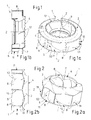
- an inventive fan wheel 1 to be driven in rotation about a rotation axis Z comprises a cover disk 2 with a preferably substantially central inlet opening 4 for air inlet, a bottom disk 6 opposite in the axial direction Z and a plurality of fan blades 8.
- These fan blades 8 are located between the bottom disk 6 and the Cover disc 2 arranged or formed entirely or partially by a specific shaping of the bottom plate 6 and / or the cover plate 2 (see. Fig. 8 ), wherein the discs 2, 6 are then connected directly in these areas.
- the fan blades 8 are arranged in a certain circumferential distribution about the rotation axis Z and the inlet opening 4 around. In the circumferential direction, in each case between two adjacent fan blades 8, blade channels 10 are formed, which lead radially or diagonally outwardly from the region of the inlet opening 4 and form outlet openings 11 on the outer region of the fan wheel 1.
- the blade channels 10 are designed so large with respect to their effective flow cross-section that during operation a turbulent flow with a Reynolds number Re »2300 at high efficiency between 0.6 and 1.0 is achieved.
- the inlet opening 4 has an effective suction mouth flow distance D s whose ratio to an effective flow distance D k of each blade channel is in any case less than 10, in particular even less than 3.
- the mentioned flow widths are usually related to a circular shape, so that an idealized diameter is used as a basis, even if the actual flow cross sections deviate from the circular shape.
- the cover disk 2 or the bottom disk 6 or each of the two disks 2, 6 it is now essential for the cover disk 2 or the bottom disk 6 or each of the two disks 2, 6 to have a non-rotationally symmetrical geometry for influencing the flow.
- the cover plate 2 and the bottom plate 6 are not parallel to each other.
- Non-rotational symmetry in the sense of the present invention is when the lying in the planes E1 and E2 cross-sectional areas of respective disc 2 and / or 6 differ - at different circumferential angles - from each other.
- the geometry deviation of two different cuts containing the rotation axis Z in the radial direction (radius r in FIG Fig. 10 ) be arbitrary. This means that both punctiform and jump-like courses are possible here.
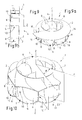
- Fig. 1 In the execution according to Fig. 1 is the cover plate 2 in the region of the inlet opening 4 equipped with a wheel inlet 12, wherein the cover plate 2 is executed in the region of this wheel inlet 12 non-rotationally symmetrical in the direction of the axis of rotation Z.
- the wheel inlet 12 extends web-like axially away from the cover plate 2 and has in the circumferential direction on a wavy contour with axial elevations and recesses lying therebetween.
- the fan wheel 1 is designed in this case as a centrifugal fan.
- the Cover disk 2 in the region of the inlet opening 2 and the Radeinlasses 12 also be formed non-rotationally symmetrical in the radial direction.
- Fig. 2 it is a radial fan, in which case only the cover plate 2 is non-rotationally symmetrical in the direction of the axis of rotation Z.
- the cover plate 2 is designed to be wavy in the circumferential direction, wherein in each case between two fan blades 8, a convex outwardly bulging portion is formed. These sections are continuous in the area of each fan blade 8 into each other.
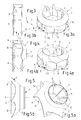
- Fig. 3 an embodiment is shown as a radial fan, in which only the bottom plate 6 is non-rotationally symmetrical in the axial direction Z executed. Specifically, it may be a similar design, as in the cover plate 2 according to Fig. 2 is provided.
- FIG. 5 an embodiment of the fan wheel 1 is illustrated as a diagonal fan, wherein the cover plate 2 in the radial direction r is non-rotationally symmetrical, in this case not steadily, but jump-shaped. This is achieved by a non-continuous, but jumping over corners in radius course of an outer peripheral edge 14 of the cover plate 2.
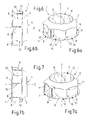
- the Fig. 6 shows an embodiment as a radial fan, wherein the cover plate 2 is designed in the radial direction r non-rotationally symmetrical, namely point-like. This means that the cover plate 2 here has a continuous circumferential course without corners or other cracks.
- the Fig. 8 shows an embodiment as a radial fan, both discs, both the cover plate 2 and the bottom plate 6, are executed by a circumferentially wavy contour in the direction of the axis of rotation Z non-rotationally symmetrical.
- the cover disk 2 and the bottom disk 6 are directly connected to one another in the outer circumferential region of the fan wheel 1 and thus together form at least a portion of the fan blades 8.
- the fan blades 8 could be completely formed by the fact that the correspondingly shaped bottom and / or cover plates 6, 2 are connected directly to one another over the entire course of the blades 8.
- the discs 2, 6 are connected to each other only in the outer peripheral region, wherein 10 conventional blade sections are formed as separate parts in the inner inlet region of the blade channels.
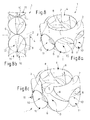
- the non-rotationally symmetric design produces geometric structures which are periodically recurring in the circumferential direction.
- FIG. 9 This is an embodiment in Fig. 9 illustrated. Again, this is a centrifugal fan with non-rotationally symmetrical cover plate 2. This has at a peripheral point 16 a leaps and bounds changing radius r, and the outer peripheral edge 14 of the cover plate 2 extends from the peripheral point 16 with a continuously changing radius over the circumference and ends after 360 ° again at the radius jump in the peripheral point 16. As a result, in this example, the peripheral edge 14 is spiraled.
- the fan blades 8 may have any desired course. For example, they may be curved forward or backward with respect to the direction of rotation.
- the invention is not limited to the illustrated and described embodiments, but also includes all the same in the context of the invention embodiments. It is expressly emphasized that the exemplary embodiments are not limited to all the features in combination, but each individual feature may also have an inventive meaning detached from all other features. Furthermore, the invention has not yet been defined in the respective independent claim Feature combination limited, but can also be defined by any other combination of certain features of all the individual features disclosed. This means that in principle virtually every individual feature of the respective independent claim can be omitted or replaced by at least one individual feature disclosed elsewhere in the application. In this respect, the claims are to be understood merely as a first formulation attempt for an invention.
Landscapes
- Engineering & Computer Science (AREA)
- Mechanical Engineering (AREA)
- General Engineering & Computer Science (AREA)
- Structures Of Non-Positive Displacement Pumps (AREA)
Priority Applications (5)
| Application Number | Priority Date | Filing Date | Title |
|---|---|---|---|
| KR1020110016107A KR101764430B1 (ko) | 2010-02-26 | 2011-02-23 | 레이디얼 또는 다이어고날 팬 임펠러 |
| US13/034,295 US8932019B2 (en) | 2010-02-26 | 2011-02-24 | Radial or diagonal fan wheel |
| CA2732714A CA2732714A1 (fr) | 2010-02-26 | 2011-02-28 | Tourniquet de ventilateur radial ou diagonal |
| JP2011042557A JP5804348B2 (ja) | 2010-02-26 | 2011-02-28 | 遠心式送風機または斜流送風機に用いられるインペラ |
| CN201110049513.8A CN102168684B (zh) | 2010-02-26 | 2011-02-28 | 径流式或斜流式风扇叶轮 |
Applications Claiming Priority (1)
| Application Number | Priority Date | Filing Date | Title |
|---|---|---|---|
| DE102010009566A DE102010009566A1 (de) | 2010-02-26 | 2010-02-26 | Radial- oder Diagonal-Ventilatorrad |
Publications (1)
| Publication Number | Publication Date |
|---|---|
| EP2363609A1 true EP2363609A1 (fr) | 2011-09-07 |
Family
ID=43806947
Family Applications (1)
| Application Number | Title | Priority Date | Filing Date |
|---|---|---|---|
| EP11153316A Withdrawn EP2363609A1 (fr) | 2010-02-26 | 2011-02-04 | Roue de ventilateur radiale ou diagonale |
Country Status (7)
| Country | Link |
|---|---|
| US (1) | US8932019B2 (fr) |
| EP (1) | EP2363609A1 (fr) |
| JP (1) | JP5804348B2 (fr) |
| KR (1) | KR101764430B1 (fr) |
| CN (1) | CN102168684B (fr) |
| CA (1) | CA2732714A1 (fr) |
| DE (2) | DE102010009566A1 (fr) |
Cited By (1)
| Publication number | Priority date | Publication date | Assignee | Title |
|---|---|---|---|---|
| EP3048308A1 (fr) * | 2015-01-22 | 2016-07-27 | LG Electronics Inc. | Ventilateur centrifuge |
Families Citing this family (29)
| Publication number | Priority date | Publication date | Assignee | Title |
|---|---|---|---|---|
| DE102013104849A1 (de) * | 2012-06-20 | 2013-12-24 | Vorwerk & Co. Interholding Gmbh | Lüfterrad sowie Elektromotor |
| AU2013313031B2 (en) * | 2012-09-07 | 2018-06-21 | Csr Building Products Limited | Rotor ventilator |
| WO2014036611A1 (fr) * | 2012-09-07 | 2014-03-13 | Csr Building Products Limited | Aérateur et aube pour celui-ci |
| DK2778432T3 (en) * | 2013-03-15 | 2016-01-25 | Ebm Papst Mulfingen Gmbh & Co | Fan device with flow rectifier |
| JP2016035230A (ja) * | 2014-08-01 | 2016-03-17 | 株式会社デンソー | 送風機 |
| DE102015101938A1 (de) | 2015-02-11 | 2016-08-11 | Ebm-Papst Mulfingen Gmbh & Co. Kg | Ventilatorrad und Ventilator |
| DE202015100654U1 (de) | 2015-02-11 | 2015-04-02 | Ebm-Papst Mulfingen Gmbh & Co. Kg | Ventilatorrad und Ventilator |
| DE102015118387A1 (de) | 2015-10-28 | 2017-05-04 | Ebm-Papst Mulfingen Gmbh & Co. Kg | Ventilatorrad und Ventilator |
| DE202015105729U1 (de) | 2015-10-28 | 2015-11-10 | Ebm-Papst Mulfingen Gmbh & Co. Kg | Ventilatorrad und Ventilator |
| USD821561S1 (en) * | 2016-03-21 | 2018-06-26 | Ebm-Papst Mulfingen Gmbh & Co. Kg | Fan wheel |
| USD949315S1 (en) * | 2016-06-24 | 2022-04-19 | Ebm-Papst Mulfingen Gmbh & Co. Kg | Vane damper with trailing edge |
| CN106640756A (zh) * | 2017-01-13 | 2017-05-10 | 苏州弗来特金属制品有限公司 | 一种新型动叶轮 |
| DE102017117100A1 (de) * | 2017-07-28 | 2019-01-31 | Ebm-Papst Mulfingen Gmbh & Co. Kg | Laufradteilung eines zweiteiligen Ventilatorrades |
| WO2019030867A1 (fr) * | 2017-08-09 | 2019-02-14 | 三菱電機株式会社 | Ventilateur hélicoïdal, soufflante et appareil à cycle de réfrigération |
| DE202017105384U1 (de) | 2017-09-06 | 2017-09-18 | Ebm-Papst Mulfingen Gmbh & Co. Kg | Radialgebläserad mit asymmetrischer Scheibe |
| DE102017120537A1 (de) * | 2017-09-06 | 2019-03-07 | Ebm-Papst Mulfingen Gmbh & Co. Kg | Radialgebläserad mit asymmetrischer Scheibe |
| DE102018109870A1 (de) * | 2018-04-24 | 2019-10-24 | Mdexx Gmbh | Ventilator, Verfahren zu dessen Konstruktion und Verfahren zur Abgabe von Medium |
| CN109322848B (zh) * | 2018-08-30 | 2020-12-01 | 中国航发湖南动力机械研究所 | 压气机试验件的转子组件及压气机试验件 |
| CN109356882A (zh) * | 2018-11-28 | 2019-02-19 | 苏州弗来特金属制品有限公司 | 一种动叶轮 |
| CN109654059A (zh) * | 2018-12-29 | 2019-04-19 | 追创科技(苏州)有限公司 | 叶轮和电机 |
| CN110185632B (zh) * | 2019-04-18 | 2024-05-17 | 西安热工研究院有限公司 | 可变流量的超临界工质半开式离心压缩装置及方法 |
| CN112443492A (zh) * | 2019-09-05 | 2021-03-05 | 苏州三星电子有限公司 | 一种离心风机及其离心风扇结构 |
| CN111810441A (zh) * | 2019-09-18 | 2020-10-23 | 湖南联诚轨道装备有限公司 | 风机及其制造方法和排放介质的方法 |
| DE102020103772A1 (de) * | 2020-02-13 | 2021-08-19 | Ebm-Papst St. Georgen Gmbh & Co. Kg | Ventilator mit Abdeckscheibe an der Rotorglocke |
| DE102020114389A1 (de) * | 2020-05-28 | 2021-12-02 | Ebm-Papst Mulfingen Gmbh & Co. Kg | Gebläserad mit ener nahtlosen Anbindung der Laufradschaufeln an einen Scheibenkörper |
| CN112983883B (zh) * | 2021-02-07 | 2022-08-09 | 宁波朗迪叶轮机械有限公司 | 斜流风叶 |
| KR102547499B1 (ko) * | 2021-11-03 | 2023-06-26 | 주식회사 케이마린 | 호버크래프트용 리프팅팬 |
| CN115342078B (zh) * | 2022-10-20 | 2023-03-24 | 杭州顿力电器有限公司 | 一种带模块扩压结构的高效离心风机 |
| CN116464675B (zh) * | 2023-06-20 | 2023-09-01 | 河北拓顺医疗科技有限公司 | 一种呼吸机内置风机用减震型降噪装置 |
Citations (11)
| Publication number | Priority date | Publication date | Assignee | Title |
|---|---|---|---|---|
| GB438036A (en) | 1934-05-09 | 1935-11-11 | Federated Engineers Ltd | Improvements in blowers and the like |
| DE3247453C1 (de) | 1982-12-22 | 1983-12-15 | Funken & Co GmbH, 5200 Siegburg | Ventilatorlaufrad und Verfahren zu seiner Herstellung |
| DE2940773C2 (de) | 1979-10-08 | 1986-08-14 | Punker GmbH, 2330 Eckernförde | Hochleistungs-Radialventilator |
| DE19918085A1 (de) | 1999-04-21 | 2000-10-26 | Bsh Bosch Siemens Hausgeraete | Gebläse mit einem Spiralgehäuse |
| JP2001263294A (ja) | 2000-03-23 | 2001-09-26 | Daikin Ind Ltd | 遠心式ターボ型空気機械のインペラ、遠心式ターボ型空気機械、及び空気調和装置 |
| EP1032766B1 (fr) | 1997-11-21 | 2002-03-27 | Hermann Stahl GmbH | Roue de ventilateur |
| US6450765B1 (en) * | 2000-06-19 | 2002-09-17 | Caterpillar Inc. | Sealing system for a centrifugal fan |
| DE20303443U1 (de) | 2003-03-04 | 2003-07-24 | Ziehl Abegg Ag | Radiallüfterrad |
| EP1574716A1 (fr) * | 2004-03-05 | 2005-09-14 | Matsushita Electric Industrial Co., Ltd. | Ventilateur |
| US20070116561A1 (en) | 2005-11-23 | 2007-05-24 | Hill Charles C | High efficiency fluid movers |
| EP1933039A1 (fr) | 2005-09-30 | 2008-06-18 | Daikin Industries, Ltd. | Ventilateur centrifuge et climatiseur associé |
Family Cites Families (10)
| Publication number | Priority date | Publication date | Assignee | Title |
|---|---|---|---|---|
| US2724544A (en) * | 1951-05-25 | 1955-11-22 | Westinghouse Electric Corp | Stator shroud and blade assembly |
| JPS60113095A (ja) | 1983-11-25 | 1985-06-19 | Matsushita Electric Ind Co Ltd | 送風機のインペラ |
| US4874293A (en) * | 1988-11-08 | 1989-10-17 | Gutzwiller H Leslie | Modified centrifugal airfoil fan wheel |
| JP3123288B2 (ja) * | 1993-03-02 | 2001-01-09 | 松下電器産業株式会社 | 電動送風機 |
| US6299409B1 (en) * | 1998-04-10 | 2001-10-09 | Denso Corporation | Centrifugal type blower unit |
| JP2001173595A (ja) | 1999-12-15 | 2001-06-26 | Hitachi Ltd | 遠心型羽根車 |
| ES2387063T3 (es) | 2001-06-28 | 2012-09-12 | Daikin Industries, Ltd. | Rodete para ventilador centrífugo y ventilador centrífugo equipado con el mismo |
| FR2837880B1 (fr) | 2002-03-27 | 2005-12-09 | Pompes Salmson Sa | Pompe pour faible debit et grande hauteur d'aspiration |
| JP2008223741A (ja) * | 2007-03-16 | 2008-09-25 | Daikin Ind Ltd | 遠心送風機 |
| JP2009228499A (ja) * | 2008-03-21 | 2009-10-08 | Daikin Ind Ltd | 送風機及びこれを用いた空気調和機 |
-
2010
- 2010-02-26 DE DE102010009566A patent/DE102010009566A1/de not_active Withdrawn
- 2010-02-26 DE DE202010018509.2U patent/DE202010018509U1/de not_active Expired - Lifetime
-
2011
- 2011-02-04 EP EP11153316A patent/EP2363609A1/fr not_active Withdrawn
- 2011-02-23 KR KR1020110016107A patent/KR101764430B1/ko active IP Right Grant
- 2011-02-24 US US13/034,295 patent/US8932019B2/en active Active
- 2011-02-28 JP JP2011042557A patent/JP5804348B2/ja active Active
- 2011-02-28 CN CN201110049513.8A patent/CN102168684B/zh active Active
- 2011-02-28 CA CA2732714A patent/CA2732714A1/fr active Pending
Patent Citations (13)
| Publication number | Priority date | Publication date | Assignee | Title |
|---|---|---|---|---|
| GB438036A (en) | 1934-05-09 | 1935-11-11 | Federated Engineers Ltd | Improvements in blowers and the like |
| DE2940773C2 (de) | 1979-10-08 | 1986-08-14 | Punker GmbH, 2330 Eckernförde | Hochleistungs-Radialventilator |
| DE3247453C1 (de) | 1982-12-22 | 1983-12-15 | Funken & Co GmbH, 5200 Siegburg | Ventilatorlaufrad und Verfahren zu seiner Herstellung |
| EP1032766B1 (fr) | 1997-11-21 | 2002-03-27 | Hermann Stahl GmbH | Roue de ventilateur |
| DE19918085A1 (de) | 1999-04-21 | 2000-10-26 | Bsh Bosch Siemens Hausgeraete | Gebläse mit einem Spiralgehäuse |
| JP2001263294A (ja) | 2000-03-23 | 2001-09-26 | Daikin Ind Ltd | 遠心式ターボ型空気機械のインペラ、遠心式ターボ型空気機械、及び空気調和装置 |
| US6450765B1 (en) * | 2000-06-19 | 2002-09-17 | Caterpillar Inc. | Sealing system for a centrifugal fan |
| DE20303443U1 (de) | 2003-03-04 | 2003-07-24 | Ziehl Abegg Ag | Radiallüfterrad |
| EP1574716A1 (fr) * | 2004-03-05 | 2005-09-14 | Matsushita Electric Industrial Co., Ltd. | Ventilateur |
| EP1574716B1 (fr) | 2004-03-05 | 2008-08-13 | Matsushita Electric Industrial Co., Ltd. | Ventilateur |
| EP1933039A1 (fr) | 2005-09-30 | 2008-06-18 | Daikin Industries, Ltd. | Ventilateur centrifuge et climatiseur associé |
| US20070116561A1 (en) | 2005-11-23 | 2007-05-24 | Hill Charles C | High efficiency fluid movers |
| US7455504B2 (en) | 2005-11-23 | 2008-11-25 | Hill Engineering | High efficiency fluid movers |
Cited By (3)
| Publication number | Priority date | Publication date | Assignee | Title |
|---|---|---|---|---|
| EP3048308A1 (fr) * | 2015-01-22 | 2016-07-27 | LG Electronics Inc. | Ventilateur centrifuge |
| CN105822572A (zh) * | 2015-01-22 | 2016-08-03 | Lg电子株式会社 | 离心式风扇 |
| US9989073B2 (en) | 2015-01-22 | 2018-06-05 | Lg Electronics Inc. | Centrifugal fan |
Also Published As
| Publication number | Publication date |
|---|---|
| JP5804348B2 (ja) | 2015-11-04 |
| CA2732714A1 (fr) | 2011-08-26 |
| KR101764430B1 (ko) | 2017-08-02 |
| CN102168684B (zh) | 2015-09-23 |
| KR20110098649A (ko) | 2011-09-01 |
| US8932019B2 (en) | 2015-01-13 |
| DE102010009566A9 (de) | 2012-03-01 |
| JP2011179499A (ja) | 2011-09-15 |
| US20110211963A1 (en) | 2011-09-01 |
| DE202010018509U1 (de) | 2017-03-15 |
| CN102168684A (zh) | 2011-08-31 |
| DE102010009566A1 (de) | 2011-09-01 |
Similar Documents
| Publication | Publication Date | Title |
|---|---|---|
| EP2363609A1 (fr) | Roue de ventilateur radiale ou diagonale | |
| EP2218917B1 (fr) | Roue de ventilateur radiale ou diagonale | |
| EP1948939B1 (fr) | Roue mobile de compresseur radial | |
| DE102010038074B4 (de) | Turbinenschaufelblatt | |
| EP2132414B1 (fr) | Agencement en feuillure | |
| DE202014011454U1 (de) | Gebläseeinrichtung und Außeneinheit einer Klimaanlage, welche diese umfasst | |
| DE112013001568T5 (de) | Turbinennabe mit Oberflächendiskontinuität und Turbolader damit | |
| DE102007037924A1 (de) | Strömungsarbeitsmaschine mit Ringkanalwandausnehmung | |
| DE112014001308T5 (de) | Axiallüfterbaugruppe mit freien Schaufelspitzen | |
| EP2282135B1 (fr) | Ventilateur | |
| EP2771581A1 (fr) | Roue de ventilateur axial | |
| EP3034886A1 (fr) | Aube et roue de ventilateur comprenant celle-ci | |
| EP2913479B1 (fr) | Aubes en tandem d'une turbomachine | |
| EP2913481B1 (fr) | Aubes en tandem d'une turbomachine | |
| DE202009018770U1 (de) | Radial- oder Diagonal-Ventilatorrad | |
| DE102018211809A1 (de) | Gehäuse für einen Ventilator und Ventilator | |
| EP2913480B1 (fr) | Aubes en tandem d'une turbomachine | |
| EP3368774A1 (fr) | Roue de ventilateur et ventilateur | |
| EP1582750B1 (fr) | Boitier et soufflante avec un boitier et une roue | |
| EP3375977A1 (fr) | Contournage d'une plate-forme de grille d'aube | |
| EP3181911A1 (fr) | Kantenberandung eines rotationselements und gebläserad | |
| EP4090853A1 (fr) | Boîtier pour un ventilateur et ventilateur doté d'un boîtier correspondant | |
| DE102007005384A1 (de) | Strömungsarbeitsmaschine sowie Rotorschaufel einer Strömungsarbeitsmaschine | |
| EP3561309B1 (fr) | Ventilateur, son procédé de fabrication et procédé de distribution d'un fluide | |
| DE2803468C2 (de) | Gebläserad für ein Diagonalgebläse |
Legal Events
| Date | Code | Title | Description |
|---|---|---|---|
| PUAI | Public reference made under article 153(3) epc to a published international application that has entered the european phase |
Free format text: ORIGINAL CODE: 0009012 |
|
| AK | Designated contracting states |
Kind code of ref document: A1 Designated state(s): AL AT BE BG CH CY CZ DE DK EE ES FI FR GB GR HR HU IE IS IT LI LT LU LV MC MK MT NL NO PL PT RO RS SE SI SK SM TR |
|
| AX | Request for extension of the european patent |
Extension state: BA ME |
|
| 17P | Request for examination filed |
Effective date: 20110908 |
|
| 17Q | First examination report despatched |
Effective date: 20120828 |
|
| STAA | Information on the status of an ep patent application or granted ep patent |
Free format text: STATUS: EXAMINATION IS IN PROGRESS |
|
| STAA | Information on the status of an ep patent application or granted ep patent |
Free format text: STATUS: THE APPLICATION IS DEEMED TO BE WITHDRAWN |
|
| 18D | Application deemed to be withdrawn |
Effective date: 20170419 |