EP2362239A1 - Low power, space combined, phased array radar - Google Patents
Low power, space combined, phased array radar Download PDFInfo
- Publication number
- EP2362239A1 EP2362239A1 EP11154254A EP11154254A EP2362239A1 EP 2362239 A1 EP2362239 A1 EP 2362239A1 EP 11154254 A EP11154254 A EP 11154254A EP 11154254 A EP11154254 A EP 11154254A EP 2362239 A1 EP2362239 A1 EP 2362239A1
- Authority
- EP
- European Patent Office
- Prior art keywords
- radar
- antenna elements
- radar units
- antenna
- units
- Prior art date
- Legal status (The legal status is an assumption and is not a legal conclusion. Google has not performed a legal analysis and makes no representation as to the accuracy of the status listed.)
- Ceased
Links
Images


Classifications
-
- G—PHYSICS
- G01—MEASURING; TESTING
- G01S—RADIO DIRECTION-FINDING; RADIO NAVIGATION; DETERMINING DISTANCE OR VELOCITY BY USE OF RADIO WAVES; LOCATING OR PRESENCE-DETECTING BY USE OF THE REFLECTION OR RERADIATION OF RADIO WAVES; ANALOGOUS ARRANGEMENTS USING OTHER WAVES
- G01S7/00—Details of systems according to groups G01S13/00, G01S15/00, G01S17/00
- G01S7/02—Details of systems according to groups G01S13/00, G01S15/00, G01S17/00 of systems according to group G01S13/00
- G01S7/03—Details of HF subsystems specially adapted therefor, e.g. common to transmitter and receiver
-
- G—PHYSICS
- G01—MEASURING; TESTING
- G01S—RADIO DIRECTION-FINDING; RADIO NAVIGATION; DETERMINING DISTANCE OR VELOCITY BY USE OF RADIO WAVES; LOCATING OR PRESENCE-DETECTING BY USE OF THE REFLECTION OR RERADIATION OF RADIO WAVES; ANALOGOUS ARRANGEMENTS USING OTHER WAVES
- G01S13/00—Systems using the reflection or reradiation of radio waves, e.g. radar systems; Analogous systems using reflection or reradiation of waves whose nature or wavelength is irrelevant or unspecified
- G01S13/02—Systems using reflection of radio waves, e.g. primary radar systems; Analogous systems
- G01S13/06—Systems determining position data of a target
- G01S13/42—Simultaneous measurement of distance and other co-ordinates
- G01S13/44—Monopulse radar, i.e. simultaneous lobing
-
- H—ELECTRICITY
- H01—ELECTRIC ELEMENTS
- H01Q—ANTENNAS, i.e. RADIO AERIALS
- H01Q3/00—Arrangements for changing or varying the orientation or the shape of the directional pattern of the waves radiated from an antenna or antenna system
- H01Q3/26—Arrangements for changing or varying the orientation or the shape of the directional pattern of the waves radiated from an antenna or antenna system varying the relative phase or relative amplitude of energisation between two or more active radiating elements; varying the distribution of energy across a radiating aperture
- H01Q3/30—Arrangements for changing or varying the orientation or the shape of the directional pattern of the waves radiated from an antenna or antenna system varying the relative phase or relative amplitude of energisation between two or more active radiating elements; varying the distribution of energy across a radiating aperture varying the relative phase between the radiating elements of an array
- H01Q3/34—Arrangements for changing or varying the orientation or the shape of the directional pattern of the waves radiated from an antenna or antenna system varying the relative phase or relative amplitude of energisation between two or more active radiating elements; varying the distribution of energy across a radiating aperture varying the relative phase between the radiating elements of an array by electrical means
-
- G—PHYSICS
- G01—MEASURING; TESTING
- G01S—RADIO DIRECTION-FINDING; RADIO NAVIGATION; DETERMINING DISTANCE OR VELOCITY BY USE OF RADIO WAVES; LOCATING OR PRESENCE-DETECTING BY USE OF THE REFLECTION OR RERADIATION OF RADIO WAVES; ANALOGOUS ARRANGEMENTS USING OTHER WAVES
- G01S13/00—Systems using the reflection or reradiation of radio waves, e.g. radar systems; Analogous systems using reflection or reradiation of waves whose nature or wavelength is irrelevant or unspecified
- G01S13/02—Systems using reflection of radio waves, e.g. primary radar systems; Analogous systems
- G01S2013/0236—Special technical features
- G01S2013/0245—Radar with phased array antenna
- G01S2013/0254—Active array antenna
Definitions
- the present invention provides a radar that will permit: 1) a simple fixed beam; 2) electronic beam steering via coherent phase locked loop (PLL) phase shifts among the elements or subarrays; and/or 3) digital beam forming via digital phase adjustment and amplitude weighting of samples.
- Digital beam forming permits beam steering and the potential for multiple simultaneous beams.
- the present invention includes a plurality of mini radars that make the radar system conformable to the structure that it is attached or built into. Phase errors caused by arbitrary curvature of a vessel or fuselage or vehicle, etc., can be corrected at each distributed mini radar.
- the phase error caused by the physical location of the mini-radar is compensated by a phase or frequency offset in addition to the nominal phase shift needed for beam steering and amplitude loss due to angular offset can be compensated by a digital amplitude multiplier.
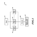
- FIGURE 1 is a block diagram of a radar system formed in accordance with an embodiment of the present invention
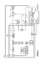
- FIGURE 2 is a schematic diagram of a circuit design used in the system shown in FIGURE 1 ;
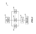
- FIGURE 3 is a block diagram of a radar system formed in accordance with an alternate embodiment of the present invention.
- FIGURE 4 is a schematic diagram of a circuit design used in the system shown in FIGURE 3 ;
- FIGURE 5-1 is a front plan view of a radar system in accordance with an embodiment of the present invention.
- FIGURE 5-2 is a top view of the radar system of FIGURE 5-1 ;
- FIGURE 5-3 is a back plan view of the radar system of FIGURE 5-1 ;
- FIGURE 6 is a block diagram of a first example radar system
- FIGURES 7 and 8 are block diagrams illustrating an elevation monopulse configuration
- FIGURE 9 is a top view of a vehicle with multiple radar systems described in any of the previous figures.
- FIGURE 1 illustrates an exemplary radar system 30 that includes multiple radar units 36 (mini frequency-modulated/continuous-wave (FM/CW) radars or Linear FM Pulse Compression).
- Each of the radar units 36 is phase locked to a master timing oscillator (a clock 34).
- Each radar unit 36 can have its transmitted modulation phase or FFT Processed receive signal adjusted (I&Q FFT Outputs multiplied by complex weight) such that a passive phase shifter function in a common phased array is performed.
- output power from each of the radar units 36 is adjustable to allow amplitude taper on an array of antennas, to adjust beam steering, or both.
- the system 30 includes a processor 40 that is connected to each of the radar units 36 and a display or other type of output device 44 that is in signal communication with the processor 40. Adjusting the relative phase of digital phase lock loops within each of the radar units 36 permits electronic beam steering, electronic beam forming, or both. Also, an output level of transmitters within each of the radar units 36 is adjustable by electronic programming, such that an amplitude taper is applied across an antenna located within the radar units 36 to achieve low side lobe levels or multiple digitally formed beams.
- FIGURE 2 illustrates details of the radar unit 36.
- the radar unit 36 includes a multichip module (MCM) 60 that includes Pulse Compression or FM/CW radar components such as that described in U.S. Patent No. 7,239,266, issued July 3, 2007 , which is herein incorporated by reference.
- MCM multichip module
- the radar unit 36 also includes a direct digital synthesizer (DDS) 62, a programmable logic device (PLD) or a field-programmable gate array (FPGA) controller 64, an intermediate frequency (IF) strip 72, an analog-to-digital (A/D) converter 76, an external delay component 70, a circulator 66, and an antenna array 68 (see element or sub-array 160 in FIGURES 5-1 and 5-2 ).
- DDS direct digital synthesizer
- PLD programmable logic device
- FPGA field-programmable gate array
- the FPGA controller 64 controls the DDS 62 and a digital attenuator 80 located within the MCM 60.
- the external delay component 70 causes a delay of a signal produced by a voltage control oscillator (VCO) 82 and sends that signal to a first mixer 84 within the MCM 60.
- the first mixer 84 within the MCM 60 combines the signal delayed by the external delay component 70 with a signal received by the antenna array 68 via the circulator 66.
- the output of the first mixer 84 is sent to the IF strip 72, that amplifies and applies a high pass filter and a band-limiting low-pass filter to the signal and sends the resulting signal to the A/D converter 76, which converts the signal to digital and sends it to the processor 40.
- the MCM 60 produces a transmission signal that is outputted by the antenna element or sub-array 68, 160 via the circulator 66.
- the clock 34 is connected to the DDS 62 and a second mixer 86 within the MCM 40.
- the second mixer 86 adds the output of the DDS 62 to the clock signal to produce a signal that is sent to a Phase-Frequency Detector (PFD) 88 as a variable frequency reference after filtering.
- PFD 88 compares the upconverted DDS signal with a divided-down signal from the output of the VCO 82.
- the difference in frequency and or phase between the two signals is converted into an error voltage for delivery to a phased-locked loop (PLL) filter and buffer amplifier 90 that produces a control signal for the VCO 82. If the physical size of the phase lock loop buffer amplifier 90 or any passive elements in filter are too large to be included in the MCM they may be added externally to the MCM.
- PLL phased-locked loop
- the FPGA controller 64 includes memory and or computational capability to generate the desired modulation waveforms.
- the FPGA controller 64 connects to the DDS 62 and the digital attenuator 80 via a high-speed serial or parallel data bus.
- the antenna element or sub-array 68, 160 is directly integrated with the other components of the radar unit 36 in order to provide a radar signal with a very low voltage standing wave ratio (VSWR) (less than 1.2:1) across an entire operating bandwidth. Also, phase noise of the radar unit 36 is not worse than approximately -100 dBc/Hz at 100 KHz offset from the transmit frequency. The phase noise is cancelled at the first mixer 84, due to the output of the external delay component 70. In other words, the time of arrival of energy reflected from an input port of the antenna element or sub-array 160 arrives at virtually the same time as the local oscillator signal (signal outputted by the VCO 82 within the MCM 60).
- VSWR voltage standing wave ratio
- the phase noise of the clock 34 is less than -145 dBc/Hz at 100 KHz from the clock frequency.
- the low phase noise of the clock 34 assures that any multiplication of this phase noise within the MCM 60 remains acceptably low and that the A/D clock supplied by a frequency divider from the master clock 34 is achieved with exceptionally low jitter, thus assuring maximum possible signal-to-noise ratio.
- the DDS 62 provides a sweep reference frequency and includes a digital-to-analog (D/A) converter having at least twelve bits for the lowest possible phase noise.
- FIGURE 3 illustrates a radar system 100 formed in accordance with an alternate embodiment of the present invention.
- the radar system 100 includes one or more radar units 102 that are connected to a common clock, synthesizer, and controller 104. Like the radar system 30, the radar units 102 are connected to the processor 40, which is then in signal communication with the output device 44.
- each of the radar units 102 includes the MCM 60, the external delay unit 70, the circulator 66, the antenna array 68, the IF strip 72, and the A/D converter 76.
- the connections of these components are similar to that of the radar unit 36 shown in FIGURE 2 .
- the clock, synthesizer, controller unit 104 includes the master clock 34, the DDS 62, and the FPGA controller 64 that are connected in a similar manner as that described with regard to the radar units 36, as shown in FIGURE 2 . Because the radar units 102 share one DDS and FPGA controllers with other radar units 102, digital steering of radar signals produced by the plurality of radar units 102 cannot be performed like they can in the radar system 30 described above. This configuration is used where a transmitted beam steering is not required but multiple digitally formed receive beams are required.
- the single source of modulation and clock reference produces a single beam that may be divided into sub-regions by multiple receive beams formed as shown in FIGURE 6 or 8 .
- FIGURES 5-1, 5-2, and 5-3 illustrate an exemplary layout of thirteen radar units 168 coupled to corresponding vertical antenna arrays 158.
- each of the vertical antenna arrays 158 includes four antenna elements 160 (i.e., microstrip patch elements).
- the vertical antenna arrays 158 are separated by an isolation wall 162.
- An exemplary isolation wall is formed of a carbon fiber material or a comparable material for performing 25 to 30 dB isolation between the vertical antenna arrays 158.
- the antenna elements 160 and the isolation walls 162 are mounted to an antenna circuit board 164.
- Each of the radar units 168 is mounted to radar circuit boards.
- the radar circuit boards are mounted to the antenna circuit board 164 on a side that is opposite the antenna elements 160.
- Located above the radar units 168 is a circuit component 172. Electrical traces connect the antenna elements 160 through the antenna circuit board 164 to their respective radar units 168 or the circuit component 172.
- the circuit component 172 includes the master clock 34, such as that shown in FIGURES 1 and 2 , or includes the master clock 34, the DDS 162, and the FPGA controller 64, such as that shown in FIGURES 3 and 4 .
- Multiple transmit beams may also be formed simultaneously.
- the multiple transmit beams are formed by combining subsections of the available overall array to form individual beams. For example, if there are 12 array elements in azimuth fed by 12 "mini-radars" then one beam is produced on the left from the left most 6 elements and another beam is produced on the right with the other half. A beam will be formed independently for each subset of associated modules.
- Beam transmission can take on a dynamic quality. For example, for a short period one beam is transmitted then in the next moment two beams are transmitted independently. The available power associated with each transmit beam is reduced in direct proportion to the number of beams that are formed. The receive beams that can be formed are constrained to exist within the illumination of each transmit beam. So the larger the number of transmit beams the greater the beamwidth and the more scanning volume is available within the beam.
- the digital beam forming can create a beam that points in any desired direction, however if no transmitter power is radiated in the steered direction then no target power can be received from that direction. There may be other reasons for steering to look where no signals were transmitted. For example, it is possible to locate the direction of a jammer by locating the max detected power, or to listen to a broadcast data transmission from a source that is not a radar.
- the present invention allows for simultaneous datalinking and radar operations.
- FIGURE 6 illustrates a plurality of subarray antennas 202 similar to those described above, each of which is connected to a separate FM/CW or Pulse Compression radar 204 with a master clock 206 that sends a clock signal to each of the FM/CW or Pulse Compression radars 204.
- a phase and amplitude controller 208 e.g., DSP Controller
- the outputs of the FM/CW radars 204 are sent to a processor (e.g., the processor 40).
- the processor performs a fast-Fourier transform (FFT) of the received signals from the FM/CW radars 204 to produce spectral I and Q values.
- FFT fast-Fourier transform
- the processor then performs one or more digital beam-forming processes (see blocks 212-216) that electronically steer the beam by re-using the original FFT I&Q data with appropriate complex weights and summation.
- the quadrature baseband I and Q values can be used to represent a radio signal as a complex vector (phasor) with real and imaginary parts. Two components are required so that both positive and negative frequencies (relative to the channel center frequency) can be represented as follows:
- the complex baseband signals are multiplied by the complex weights to apply the phase shift and amplitude scaling required for each antenna element.
- w k a k ⁇ e jsin ⁇ k
- a k is the relative amplitude of the weight
- ⁇ k is the phase shift of the weight (i.e., differential phase shift)
- ⁇ k 360(d/ ⁇ )sin( ⁇ )
- d is the spacing between antenna elements
- ⁇ is the freespace wavelength
- ⁇ is in the desired scan angle in degrees.
- the sum channel signal is also connected to a circulator (e.g. the circulator 66) of the radar system 280.
- Another receiver (not shown) receives the output of the Elevation Delta Channel.
- the Sum Channel is used to both transmit the signal and receive the main sum signal.
- the hybrid is located within the radar unit 168.
- a processor performs target detection using the collection of elevation summation beams from the sum channels of the 180-degree hybrid components 290. Also, the processor performs target tracking using an azimuth monopulse tracking via digital beam forming algorithm during receive processing and elevation monopulse tracking by comparing phase and amplitude of the signal in the summation channel with the phase and amplitude of the elevation delta channel.
- the Azimuth and Elevation Monopulse Beam former algorithm can be expressed mathematically for Elevation Monopulse as follows: vector sum from 0 to N/2 of the upper half of all antenna elements minus the vector sum of N/2 to N of the lower half of the elements shifted by 180 degrees.
- the Azimuth monopulse tracking beam is formed by the vector sum of the left half of the array and subtracting the vector sum of the right half of the array elements phase shifted by 180 degrees.
- FIGURE 9 several fix-mounted, electronically scanned antennas 350 coupled to a processor, as described above, are placed around a pilot house of a (marine or land-based) vehicle 320 to provide panoramic or 360-degree coverage with very high range resolution of a few feet to identify small skiffs at sea and alert security details onboard, etc.
- Combatants cannot readily see the simple thin active antenna structures that do not mechanically move and do not attract attention.
- combatants are known to shoot at and attempt to destroy visible satellite antennas, rotating marine radar antennas.
- Other exemplary radar applications include, but are not limited to: 1) covert littoral small craft operations; 2) marine barge radars used within the very narrow confines of (e.g. European and U.S.) rivers, locks, and canals where marine radar carriage is mandated; and 3) antipirate applications onboard cargo ships.
Landscapes
- Engineering & Computer Science (AREA)
- Radar, Positioning & Navigation (AREA)
- Remote Sensing (AREA)
- Computer Networks & Wireless Communication (AREA)
- Physics & Mathematics (AREA)
- General Physics & Mathematics (AREA)
- Radar Systems Or Details Thereof (AREA)
Applications Claiming Priority (2)
| Application Number | Priority Date | Filing Date | Title |
|---|---|---|---|
| US30627110P | 2010-02-19 | 2010-02-19 | |
| US13/011,771 US8633851B2 (en) | 2010-02-19 | 2011-01-21 | Low power, space combined, phased array radar |
Publications (1)
| Publication Number | Publication Date |
|---|---|
| EP2362239A1 true EP2362239A1 (en) | 2011-08-31 |
Family
ID=46233683
Family Applications (1)
| Application Number | Title | Priority Date | Filing Date |
|---|---|---|---|
| EP11154254A Ceased EP2362239A1 (en) | 2010-02-19 | 2011-02-11 | Low power, space combined, phased array radar |
Country Status (3)
| Country | Link |
|---|---|
| US (2) | US8633851B2 (https=) |
| EP (1) | EP2362239A1 (https=) |
| JP (1) | JP5743586B2 (https=) |
Cited By (7)
| Publication number | Priority date | Publication date | Assignee | Title |
|---|---|---|---|---|
| CN109274370A (zh) * | 2018-09-29 | 2019-01-25 | 北京望远四象科技有限公司 | 用于毫米波雷达的扫频源和无人机系统 |
| CN111630792A (zh) * | 2017-11-15 | 2020-09-04 | 弗劳恩霍夫应用研究促进协会 | 装置、测量系统和测量设置以及用于测试装置的方法 |
| US20200341138A1 (en) * | 2016-07-29 | 2020-10-29 | Remote Sensing Solutions, Inc | Mobile radar for visualizing topography |
| US10830873B2 (en) | 2017-01-06 | 2020-11-10 | Honeywell International Inc. | Synthesizer for radar sensing |
| CN112259964A (zh) * | 2020-09-28 | 2021-01-22 | 西南电子技术研究所(中国电子科技集团公司第十研究所) | 多子阵相控阵天线波束控制装置 |
| CN115313064A (zh) * | 2022-08-19 | 2022-11-08 | 合肥工业大学 | 一种频率扫描装置 |
| US11630203B2 (en) | 2019-06-25 | 2023-04-18 | Raytheon Company | Ground station sensing of weather around an aircraft |
Families Citing this family (51)
| Publication number | Priority date | Publication date | Assignee | Title |
|---|---|---|---|---|
| US8633851B2 (en) * | 2010-02-19 | 2014-01-21 | Honeywell International Inc. | Low power, space combined, phased array radar |
| US9660339B2 (en) * | 2010-12-04 | 2017-05-23 | Chian Chiu Li | Beam steering and manipulating apparatus and method |
| DE102011075552A1 (de) * | 2011-05-10 | 2012-11-15 | Robert Bosch Gmbh | Schaltungsanordnung für Radaranwendungen |
| EP2631747B1 (en) | 2012-02-24 | 2016-03-30 | BlackBerry Limited | Method and apparatus for providing a user interface on a device that indicates content operators |
| FR2995088B1 (fr) * | 2012-08-28 | 2015-08-21 | Rockwell Collins France | Systeme pour proteger une plateforme aeroportee contre des collisions |
| US9000974B2 (en) | 2012-09-10 | 2015-04-07 | Honeywell International Inc. | Systems and methods for frequency-modulation continuous-wave and pulse-compression transmission operation |
| US9194946B1 (en) | 2012-09-10 | 2015-11-24 | Honeywell International Inc. | Combined FMCW and FM pulse-compression radar systems and methods |
| US9188670B2 (en) | 2012-10-17 | 2015-11-17 | Raytheon Company | Interferometric inverse synthetic aperture radar and method |
| US9547076B2 (en) | 2012-10-17 | 2017-01-17 | Raytheon Company | Elevation monopulse antenna synthesis for azimuth connected phase array antennas and method |
| US9128189B1 (en) * | 2012-11-26 | 2015-09-08 | Rockwell Collins, Inc. | Hybrid pulsed-FMCW multi-mode airborne and rotary wing radar ESA device and related method |
| EP2775273B1 (de) * | 2013-03-08 | 2020-11-04 | VEGA Grieshaber KG | Multi-System-Radar für die Füllstandmessung |
| US8982931B2 (en) * | 2013-03-15 | 2015-03-17 | Raytheon Company | RF puck |
| US9972917B2 (en) | 2013-10-03 | 2018-05-15 | Honeywell International Inc. | Digital active array radar |
| US9897695B2 (en) | 2013-10-03 | 2018-02-20 | Honeywell International Inc. | Digital active array radar |
| EP2881752B1 (en) * | 2013-12-03 | 2017-05-10 | Nxp B.V. | A multichip automotive radar system, a radar chip for such as system, and a method of operating such a system |
| US9915728B2 (en) * | 2014-01-10 | 2018-03-13 | Raytheon Company | Sub-diffraction limit resolution radar arrays |
| US9841497B2 (en) * | 2014-06-05 | 2017-12-12 | Infineon Technologies Ag | Method, device and system for processing radar signals |
| US9945931B2 (en) | 2014-12-12 | 2018-04-17 | University Of Kansas | Techniques for navigating UAVs using ground-based transmitters |
| CA2980920C (en) * | 2015-03-25 | 2023-09-26 | King Abdulaziz City Of Science And Technology | Apparatus and methods for synthetic aperture radar with digital beamforming |
| JP6746882B2 (ja) * | 2015-07-28 | 2020-08-26 | 日本電気株式会社 | レーダ装置およびレーダ装置の制御方法 |
| US10324166B2 (en) * | 2015-09-28 | 2019-06-18 | Rockwell Collins, Inc. | Affordable combined pulsed/FMCW radar AESA |
| US10079633B2 (en) | 2015-09-29 | 2018-09-18 | The United States Of America, As Represented By The Secretary Of The Army | Time-based and frequency-based radio beamforming waveform transmission |
| US10320467B2 (en) | 2015-09-29 | 2019-06-11 | The United States Of America, As Represented By The Secretary Of The Army | Frequency-based radio beamforming waveform transmission |
| US10193612B2 (en) * | 2015-09-29 | 2019-01-29 | The United States Of America, As Represented By The Secretary Of The Army | Time-based radio beamforming waveform transmission |
| IL242588B (en) * | 2015-11-12 | 2022-07-01 | Israel Aerospace Ind Ltd | Electromagnetic homing head architecture |
| WO2017084700A1 (de) | 2015-11-17 | 2017-05-26 | Vega Grieshaber Kg | Antennenvorrichtung und verfahren zum senden und/oder empfangen eines signals |
| EP3380864A4 (en) | 2015-11-25 | 2019-07-03 | Urthecast Corp. | APPARATUS AND METHODS FOR OPEN SYNTHESIS RADAR IMAGING |
| KR101797606B1 (ko) * | 2016-01-29 | 2017-11-14 | 주식회사 산엔지니어링 | 선박용 고정 구조의 레이더 안테나 장치 |
| KR102391485B1 (ko) * | 2016-03-17 | 2022-04-28 | 삼성전자주식회사 | 무선 통신 시스템에서 빔을 송신하기 위한 방법 및 장치 |
| EP3255392B1 (de) * | 2016-06-07 | 2020-04-22 | VEGA Grieshaber KG | Füllstandradar zur sendeseitigen strahlformung mittels paralleler phasenregelschleifen |
| US10345439B2 (en) * | 2016-11-04 | 2019-07-09 | GM Global Technology Operations LLC | Object detection in multiple radars |
| EP3631504B8 (en) | 2017-05-23 | 2023-08-16 | Spacealpha Insights Corp. | Synthetic aperture radar imaging apparatus and methods |
| US10564274B2 (en) * | 2017-09-05 | 2020-02-18 | Analog Devices, Inc. | Phase or delay control in multi-channel RF applications |
| DE102017217805B4 (de) * | 2017-10-06 | 2019-05-02 | Vega Grieshaber Kg | Radarfüllstandmessgerät mit Synchronisationssignal auf verschiedenen Leitungstypen |
| CA3083033A1 (en) | 2017-11-22 | 2019-11-28 | Urthecast Corp. | Synthetic aperture radar apparatus and methods |
| EP3502733B1 (en) * | 2017-12-19 | 2023-02-15 | NXP USA, Inc. | Radar system comprising coupling device |
| GB2569827B (en) * | 2018-01-02 | 2022-03-30 | S&Ao Ltd | A radar device |
| DE102018200647A1 (de) * | 2018-01-16 | 2019-07-18 | Vega Grieshaber Kg | Radar-transceiver-chip |
| DE102018202296A1 (de) | 2018-02-15 | 2019-08-22 | Robert Bosch Gmbh | Radarsensor-System und Verfahren zum Betreiben eines Radarsensor-Systems |
| DE102018203934A1 (de) * | 2018-03-15 | 2019-09-19 | Robert Bosch Gmbh | Radarsensorsystem und Verfahren zum Betreiben eines Radarsensorsystems |
| US11105921B2 (en) | 2019-02-19 | 2021-08-31 | Honeywell International Inc. | Systems and methods for vehicle navigation |
| KR102737855B1 (ko) * | 2019-02-28 | 2024-12-03 | 에이-엘렉트로닉 디.오.오. | 소형화된 무선 주파수 신호 검출기에서 노이즈를 억제하고 속도를 높이기 위한 방법 |
| US11378986B2 (en) | 2019-04-01 | 2022-07-05 | Honeywell International Inc. | Systems and methods for landing and takeoff guidance |
| KR102834783B1 (ko) * | 2019-04-30 | 2025-07-17 | 젠다르 인코퍼레이티드 | 레이더 데이터 결합 시스템 및 방법 |
| DE102019124850B4 (de) * | 2019-09-16 | 2021-08-12 | Infineon Technologies Ag | Phasenoptimierung für die verbesserte Detektion von Radarzielen |
| CN110673139B (zh) * | 2019-10-22 | 2022-04-05 | 成都汇蓉国科微系统技术有限公司 | 一种目标探测雷达系统脉冲压缩系数生成方法及装置 |
| US20240012105A1 (en) * | 2021-01-08 | 2024-01-11 | Saab Ab | A monostatic radar system |
| US12153162B2 (en) * | 2021-02-18 | 2024-11-26 | The United States Of America Represented By The Secretary Of The Navy | Ground based radar cross section measurement of countermeasures |
| WO2024049351A1 (en) * | 2022-09-01 | 2024-03-07 | St Engineering Urban Solutions Ltd. | Radar-based parking occupancy sensor |
| DE102023203975A1 (de) * | 2023-04-28 | 2024-10-31 | Robert Bosch Gesellschaft mit beschränkter Haftung | Radarsystem und Verfahren zum Betreiben eines Radarsystems |
| WO2025255842A1 (zh) * | 2024-06-14 | 2025-12-18 | 清华大学 | 一种分布式雷达收发机系统 |
Citations (6)
| Publication number | Priority date | Publication date | Assignee | Title |
|---|---|---|---|---|
| EP0733913A2 (en) * | 1995-03-23 | 1996-09-25 | Honda Giken Kogyo Kabushiki Kaisha | Radar module and antenna device |
| US20030058133A1 (en) * | 2001-09-27 | 2003-03-27 | Arnold David V. | Vehicular traffic sensor |
| US20060164317A1 (en) * | 2003-02-01 | 2006-07-27 | Qinetiz Limited | Phased array antenna and inter-element mutual coupling control method |
| US7239266B2 (en) | 2004-08-26 | 2007-07-03 | Honeywell International Inc. | Radar altimeter |
| US7298217B2 (en) * | 2005-12-01 | 2007-11-20 | Raytheon Company | Phased array radar systems and subassemblies thereof |
| US7492313B1 (en) * | 2006-10-31 | 2009-02-17 | Lockheed Martin Corporation | Digital processing radar system |
Family Cites Families (23)
| Publication number | Priority date | Publication date | Assignee | Title |
|---|---|---|---|---|
| US5003314A (en) * | 1989-07-24 | 1991-03-26 | Cubic Defense Systems, Inc. | Digitally synthesized phase error correcting system |
| JPH04310887A (ja) * | 1991-04-09 | 1992-11-02 | Mitsubishi Electric Corp | レーダ装置 |
| JPH0522028A (ja) * | 1991-07-11 | 1993-01-29 | Nippon Telegr & Teleph Corp <Ntt> | アンテナ装置 |
| US5353033A (en) * | 1993-04-15 | 1994-10-04 | Hughes Aircraft Company | Optoelectronic phased array with digital transmit signal interface |
| JP4310887B2 (ja) | 2000-05-22 | 2009-08-12 | パナソニック株式会社 | 耳掛け形イヤホン |
| JP3941349B2 (ja) * | 2000-07-14 | 2007-07-04 | 三菱電機株式会社 | ビーム走査アンテナ |
| US6434372B1 (en) * | 2001-01-12 | 2002-08-13 | The Regents Of The University Of California | Long-range, full-duplex, modulated-reflector cell phone for voice/data transmission |
| US6486827B2 (en) * | 2001-04-18 | 2002-11-26 | Raytheon Company | Sparse frequency waveform radar system and method |
| DE10157216C1 (de) | 2001-11-22 | 2003-02-13 | Eads Deutschland Gmbh | Aktive Empfangs-Gruppenantenne |
| GB0215967D0 (en) * | 2002-07-09 | 2003-02-12 | Bae Systems Plc | Improvements in or relating to range resolution |
| US6882310B1 (en) * | 2003-10-15 | 2005-04-19 | Raytheon Company | Direct sampling GPS receiver for anti-interference operations |
| US7202824B1 (en) * | 2003-10-15 | 2007-04-10 | Cisco Technology, Inc. | Dual hemisphere antenna |
| US7161527B2 (en) | 2004-09-03 | 2007-01-09 | Honeywell International Inc. | Navigation system |
| JP4478606B2 (ja) * | 2005-05-19 | 2010-06-09 | 富士通株式会社 | リニアアレイアンテナの校正装置及び校正方法 |
| US7737879B2 (en) * | 2006-06-09 | 2010-06-15 | Lockheed Martin Corporation | Split aperture array for increased short range target coverage |
| US7450068B2 (en) * | 2006-11-20 | 2008-11-11 | The Boeing Company | Phased array antenna beam tracking with difference patterns |
| JP4840176B2 (ja) * | 2007-02-09 | 2011-12-21 | 三菱電機株式会社 | アンテナ装置 |
| US7916083B2 (en) * | 2008-05-01 | 2011-03-29 | Emag Technologies, Inc. | Vertically integrated electronically steered phased array and method for packaging |
| JP2010032497A (ja) * | 2008-07-02 | 2010-02-12 | Toshiba Corp | レーダ装置とその受信ビーム形成方法 |
| US7876261B1 (en) * | 2008-10-28 | 2011-01-25 | Lockheed Martin Corporation | Reflected wave clock synchronization |
| US8200286B2 (en) * | 2008-10-31 | 2012-06-12 | Telefonaktiebolaget L M Ericsson (Publ) | Base station and method for improving coverage in a wireless communication system using antenna beam-jitter and CQI correction |
| JP2010212895A (ja) * | 2009-03-09 | 2010-09-24 | Toshiba Corp | アンテナ装置、レーダ装置 |
| US8633851B2 (en) * | 2010-02-19 | 2014-01-21 | Honeywell International Inc. | Low power, space combined, phased array radar |
-
2011
- 2011-01-21 US US13/011,771 patent/US8633851B2/en active Active
- 2011-02-11 EP EP11154254A patent/EP2362239A1/en not_active Ceased
- 2011-02-16 JP JP2011031043A patent/JP5743586B2/ja not_active Expired - Fee Related
-
2013
- 2013-12-16 US US14/107,089 patent/US9354298B2/en active Active
Patent Citations (6)
| Publication number | Priority date | Publication date | Assignee | Title |
|---|---|---|---|---|
| EP0733913A2 (en) * | 1995-03-23 | 1996-09-25 | Honda Giken Kogyo Kabushiki Kaisha | Radar module and antenna device |
| US20030058133A1 (en) * | 2001-09-27 | 2003-03-27 | Arnold David V. | Vehicular traffic sensor |
| US20060164317A1 (en) * | 2003-02-01 | 2006-07-27 | Qinetiz Limited | Phased array antenna and inter-element mutual coupling control method |
| US7239266B2 (en) | 2004-08-26 | 2007-07-03 | Honeywell International Inc. | Radar altimeter |
| US7298217B2 (en) * | 2005-12-01 | 2007-11-20 | Raytheon Company | Phased array radar systems and subassemblies thereof |
| US7492313B1 (en) * | 2006-10-31 | 2009-02-17 | Lockheed Martin Corporation | Digital processing radar system |
Non-Patent Citations (4)
| Title |
|---|
| "Datasheet MAX2828/MAX2829 Single-/Dual-Band 802.11a/b/g World-Band Transceiver ICs", 15 August 2005 (2005-08-15), XP055105834, Retrieved from the Internet <URL:http://datasheets.maximintegrated.com/en/ds/MAX2828-MAX2829.pdf> [retrieved on 20140306] * |
| CHESTON T AND FRANK J C - SKOLNIK M I (ED): "Chapter 7: Phased Array Antennas", 1 January 1990, RADAR HANDBOOK (2ND EDITION), NEW YORK, NY : MCGRAW-HILL, US, PAGE(S) 7.1 - 7.1.82, ISBN: 978-0-07-057913-2, XP007918535 * |
| DAVID MURROW - SKOLNIK M I (ED): "Chapter 20: Height Finding and 3D Radar", 1 January 1990, RADAR HANDBOOK (2ND EDITION), NEW YORK, NY : MCGRAW-HILL, US, PAGE(S) 20/1 - 20/40, ISBN: 978-0-07-057913-2, XP007918537 * |
| KLEMBOWSKI W ET AL: "Trends in radar technology and PIT achievements", MICROWAVES, RADAR AND WIRELESS COMMUNICATIONS, 2004. MIKON-2004. 15TH INTERNATIONAL CONFERENCE ON WARSAW, POLAND MAY 17-19, 2004, PISCATAWAY, NJ, USA,IEEE, vol. 1, 17 May 2004 (2004-05-17), pages 77 - 85, XP010740766, ISBN: 978-83-906662-7-3, DOI: 10.1109/MIKON.2004.1356863 * |
Cited By (12)
| Publication number | Priority date | Publication date | Assignee | Title |
|---|---|---|---|---|
| US20200341138A1 (en) * | 2016-07-29 | 2020-10-29 | Remote Sensing Solutions, Inc | Mobile radar for visualizing topography |
| US11843180B2 (en) * | 2016-07-29 | 2023-12-12 | The Tomorrow Companies Inc. | Mobile radar for visualizing topography |
| US10830873B2 (en) | 2017-01-06 | 2020-11-10 | Honeywell International Inc. | Synthesizer for radar sensing |
| US11181616B2 (en) | 2017-01-06 | 2021-11-23 | Honeywell International Inc. | Synihesizer for radar sensing |
| EP3346284B1 (en) * | 2017-01-06 | 2023-10-04 | Honeywell International Inc. | Synthesizer for radar sensing |
| CN111630792A (zh) * | 2017-11-15 | 2020-09-04 | 弗劳恩霍夫应用研究促进协会 | 装置、测量系统和测量设置以及用于测试装置的方法 |
| CN109274370A (zh) * | 2018-09-29 | 2019-01-25 | 北京望远四象科技有限公司 | 用于毫米波雷达的扫频源和无人机系统 |
| CN109274370B (zh) * | 2018-09-29 | 2022-06-24 | 北京望远四象科技有限公司 | 用于毫米波雷达的扫频源和无人机系统 |
| US11630203B2 (en) | 2019-06-25 | 2023-04-18 | Raytheon Company | Ground station sensing of weather around an aircraft |
| CN112259964A (zh) * | 2020-09-28 | 2021-01-22 | 西南电子技术研究所(中国电子科技集团公司第十研究所) | 多子阵相控阵天线波束控制装置 |
| CN112259964B (zh) * | 2020-09-28 | 2022-09-02 | 西南电子技术研究所(中国电子科技集团公司第十研究所) | 多子阵相控阵天线波束控制装置 |
| CN115313064A (zh) * | 2022-08-19 | 2022-11-08 | 合肥工业大学 | 一种频率扫描装置 |
Also Published As
| Publication number | Publication date |
|---|---|
| US9354298B2 (en) | 2016-05-31 |
| US20120154203A1 (en) | 2012-06-21 |
| JP2011191293A (ja) | 2011-09-29 |
| US8633851B2 (en) | 2014-01-21 |
| JP5743586B2 (ja) | 2015-07-01 |
| US20140292561A1 (en) | 2014-10-02 |
Similar Documents
| Publication | Publication Date | Title |
|---|---|---|
| US9354298B2 (en) | Low power, space combined, phased array radar | |
| EP2857858B1 (en) | Digital active array radar | |
| US8730095B1 (en) | Super-angular and range-resolution with phased array antenna and multifrequency dither | |
| US8854255B1 (en) | Ground moving target indicating radar | |
| Han et al. | High-resolution phased-subarray MIMO radar with grating lobe cancellation technique | |
| EP2556385B2 (en) | Electronic counter measure system | |
| US8345716B1 (en) | Polarization diverse antenna array arrangement | |
| EP3319172B1 (en) | Airborne/spaceborne distributed aperture multi sensing pulsed rf system | |
| Yu et al. | A hybrid radar system with a phased transmitting array and a digital beamforming receiving array | |
| CN101587188A (zh) | 一种基于时间调制天线阵的单脉冲雷达系统 | |
| WO2008057286A2 (en) | Method and apparatus for microwave and millimeter-wave imaging | |
| Yeary et al. | Recent advances on an S-band all-digital mobile phased array radar | |
| Urzaiz et al. | Design, implementation and first experimental results of an X-band ubiquitous radar system | |
| EP1523785A1 (en) | Common aperture antenna | |
| Ogg | Steerable array radars | |
| O’Donnell | Radar Systems Engineering Lecture 9 Antennas | |
| Palumbo | Some examples of systems developments in Italy based on phased array technology | |
| CN217215090U (zh) | 雷达天线、雷达和机电设备 | |
| Sander | Experimental phased-array radar ELRA: antenna system | |
| Otten et al. | Light weight digital array SAR | |
| Bradsell | Phased arrays in radar | |
| US20250266624A1 (en) | Radar antenna, signal handling component and method for radar detection of an object | |
| KR102602720B1 (ko) | 위상 배열 안테나의 빔 조향 장치 | |
| Orzel et al. | Mobile X-band dual polarization phased array radar: System requirements and development | |
| US12345798B2 (en) | FMCW radar with elevation scanning |
Legal Events
| Date | Code | Title | Description |
|---|---|---|---|
| PUAI | Public reference made under article 153(3) epc to a published international application that has entered the european phase |
Free format text: ORIGINAL CODE: 0009012 |
|
| 17P | Request for examination filed |
Effective date: 20110211 |
|
| AK | Designated contracting states |
Kind code of ref document: A1 Designated state(s): AL AT BE BG CH CY CZ DE DK EE ES FI FR GB GR HR HU IE IS IT LI LT LU LV MC MK MT NL NO PL PT RO RS SE SI SK SM TR |
|
| AX | Request for extension of the european patent |
Extension state: BA ME |
|
| STAA | Information on the status of an ep patent application or granted ep patent |
Free format text: STATUS: THE APPLICATION HAS BEEN REFUSED |
|
| 18R | Application refused |
Effective date: 20141109 |