EP2357704A1 - Verfahren zur Herstellung einer SOFC Brennstoffzelle - Google Patents
Verfahren zur Herstellung einer SOFC Brennstoffzelle Download PDFInfo
- Publication number
- EP2357704A1 EP2357704A1 EP11151074A EP11151074A EP2357704A1 EP 2357704 A1 EP2357704 A1 EP 2357704A1 EP 11151074 A EP11151074 A EP 11151074A EP 11151074 A EP11151074 A EP 11151074A EP 2357704 A1 EP2357704 A1 EP 2357704A1
- Authority
- EP
- European Patent Office
- Prior art keywords
- injection molding
- molding core
- interconnector
- core
- interconnector material
- Prior art date
- Legal status (The legal status is an assumption and is not a legal conclusion. Google has not performed a legal analysis and makes no representation as to the accuracy of the status listed.)
- Granted
Links
Images

Classifications
-
- H—ELECTRICITY
- H01—ELECTRIC ELEMENTS
- H01M—PROCESSES OR MEANS, e.g. BATTERIES, FOR THE DIRECT CONVERSION OF CHEMICAL ENERGY INTO ELECTRICAL ENERGY
- H01M8/00—Fuel cells; Manufacture thereof
- H01M8/10—Fuel cells with solid electrolytes
- H01M8/12—Fuel cells with solid electrolytes operating at high temperature, e.g. with stabilised ZrO2 electrolyte
- H01M8/124—Fuel cells with solid electrolytes operating at high temperature, e.g. with stabilised ZrO2 electrolyte characterised by the process of manufacturing or by the material of the electrolyte
-
- B—PERFORMING OPERATIONS; TRANSPORTING
- B28—WORKING CEMENT, CLAY, OR STONE
- B28B—SHAPING CLAY OR OTHER CERAMIC COMPOSITIONS; SHAPING SLAG; SHAPING MIXTURES CONTAINING CEMENTITIOUS MATERIAL, e.g. PLASTER
- B28B1/00—Producing shaped prefabricated articles from the material
- B28B1/24—Producing shaped prefabricated articles from the material by injection moulding
-
- B—PERFORMING OPERATIONS; TRANSPORTING
- B28—WORKING CEMENT, CLAY, OR STONE
- B28B—SHAPING CLAY OR OTHER CERAMIC COMPOSITIONS; SHAPING SLAG; SHAPING MIXTURES CONTAINING CEMENTITIOUS MATERIAL, e.g. PLASTER
- B28B7/00—Moulds; Cores; Mandrels
- B28B7/34—Moulds, cores, or mandrels of special material, e.g. destructible materials
- B28B7/342—Moulds, cores, or mandrels of special material, e.g. destructible materials which are at least partially destroyed, e.g. broken, molten, before demoulding; Moulding surfaces or spaces shaped by, or in, the ground, or sand or soil, whether bound or not; Cores consisting at least mainly of sand or soil, whether bound or not
-
- H—ELECTRICITY
- H01—ELECTRIC ELEMENTS
- H01M—PROCESSES OR MEANS, e.g. BATTERIES, FOR THE DIRECT CONVERSION OF CHEMICAL ENERGY INTO ELECTRICAL ENERGY
- H01M8/00—Fuel cells; Manufacture thereof
- H01M8/002—Shape, form of a fuel cell
- H01M8/004—Cylindrical, tubular or wound
-
- H—ELECTRICITY
- H01—ELECTRIC ELEMENTS
- H01M—PROCESSES OR MEANS, e.g. BATTERIES, FOR THE DIRECT CONVERSION OF CHEMICAL ENERGY INTO ELECTRICAL ENERGY
- H01M8/00—Fuel cells; Manufacture thereof
- H01M8/10—Fuel cells with solid electrolytes
- H01M8/12—Fuel cells with solid electrolytes operating at high temperature, e.g. with stabilised ZrO2 electrolyte
- H01M8/1213—Fuel cells with solid electrolytes operating at high temperature, e.g. with stabilised ZrO2 electrolyte characterised by the electrode/electrolyte combination or the supporting material
-
- H—ELECTRICITY
- H01—ELECTRIC ELEMENTS
- H01M—PROCESSES OR MEANS, e.g. BATTERIES, FOR THE DIRECT CONVERSION OF CHEMICAL ENERGY INTO ELECTRICAL ENERGY
- H01M8/00—Fuel cells; Manufacture thereof
- H01M8/10—Fuel cells with solid electrolytes
- H01M8/12—Fuel cells with solid electrolytes operating at high temperature, e.g. with stabilised ZrO2 electrolyte
- H01M2008/1293—Fuel cells with solid oxide electrolytes
-
- Y—GENERAL TAGGING OF NEW TECHNOLOGICAL DEVELOPMENTS; GENERAL TAGGING OF CROSS-SECTIONAL TECHNOLOGIES SPANNING OVER SEVERAL SECTIONS OF THE IPC; TECHNICAL SUBJECTS COVERED BY FORMER USPC CROSS-REFERENCE ART COLLECTIONS [XRACs] AND DIGESTS
- Y02—TECHNOLOGIES OR APPLICATIONS FOR MITIGATION OR ADAPTATION AGAINST CLIMATE CHANGE
- Y02E—REDUCTION OF GREENHOUSE GAS [GHG] EMISSIONS, RELATED TO ENERGY GENERATION, TRANSMISSION OR DISTRIBUTION
- Y02E60/00—Enabling technologies; Technologies with a potential or indirect contribution to GHG emissions mitigation
- Y02E60/30—Hydrogen technology
- Y02E60/50—Fuel cells
-
- Y—GENERAL TAGGING OF NEW TECHNOLOGICAL DEVELOPMENTS; GENERAL TAGGING OF CROSS-SECTIONAL TECHNOLOGIES SPANNING OVER SEVERAL SECTIONS OF THE IPC; TECHNICAL SUBJECTS COVERED BY FORMER USPC CROSS-REFERENCE ART COLLECTIONS [XRACs] AND DIGESTS
- Y02—TECHNOLOGIES OR APPLICATIONS FOR MITIGATION OR ADAPTATION AGAINST CLIMATE CHANGE
- Y02P—CLIMATE CHANGE MITIGATION TECHNOLOGIES IN THE PRODUCTION OR PROCESSING OF GOODS
- Y02P70/00—Climate change mitigation technologies in the production process for final industrial or consumer products
- Y02P70/50—Manufacturing or production processes characterised by the final manufactured product
Definitions
- the present invention relates to a method for producing a SOFC fuel cell having an electrolyte body in a tubular design, wherein at least one inside electrode and one outside electrode is applied to the electrolyte body.
- Solid oxide fuel cells so-called SOFC fuel cells (Solid Oxide Fuel Cells) with ceramic electrolyte body form a high-temperature variant of fuel cells. They are operated at 600 ° C to 1,000 ° C and deliver the highest electrical efficiencies of up to about 50%.
- SOFC fuel cells are divided into two main variants: A variant forms a tubular, tubular shape of the electrolyte body, which is according to another variant to delimit against a flat, planar shape. It is necessary in the process for producing a SOFC fuel cell according to the tubular variant to apply the inside and outside electrodes to the wall of the electrolyte body.
- electrolyte body electrode usually designed as the anode, which is lapped with fuel gas, applied as a coating on the inner wall of the electrolyte body.
- the electrolyte body is preferably extruded.
- interconnectors are applied to the electrodes surface for contacting the electrodes, wherein the application on the inside of the electrolyte body often leads to problems.
- metallic interconnectors consist of a high-chromium-containing material in order to obtain a sufficient corrosion resistance combined with a sufficient electrical conductivity due to the high operating temperatures.
- the resulting during operation of the fuel cell chromium oxide layer has a negative effect on the cathode material and can lead to premature aging of the fuel cell.
- ceramic interconnectors for the electrical contacting of the electrodes are true known in the planar design, find so far for tubular SOFC fuel cells but no application.
- the application of ceramic interconnects on the inner wall of the electrolyte body is associated with significant problems.
- the electrodes themselves must also be made thin, for example, have a thickness of 50 microns.
- the interconnector layer must also be highly porous, with a thickness of the interconnector material changing over the longitudinal extension of the electrolyte body on the surface of the electrolyte body offering further advantages.
- the invention includes the technical teaching that the method for producing an SOFC fuel cell comprises at least the steps of providing an injection molding core on which at least one interconnector material and the inside electrode is applied, the method further comprising arranging the injection molding core in an injection mold, injection molding of an electrolyte mass to form the electrolyte body and removal of the injection core in the manner of a lost core casting process.
- the invention is based on the idea that for the production of the electrolyte body, a ceramic injection molding method is used, wherein the interconnector material and the inside electrode are already arranged in the injection molding step such that this or this can enter into a connection with the electrolyte body.
- an injection molding core is arranged centrally in an injection mold, so that a tubular cavity results, into which the electrolyte mass is injected in order to form the electrolyte body. Since both the interconnector material and the inside electrode are already applied to the injection molding core, the electrolyte mass can form a connection with the internal electrode, so that subsequently only the injection molding core has to be removed from the electrolyte body or from the inside electrode.
- the interconnector material is applied to the injection molding core prior to application of the inner electrode forming material so that the electrolyte composition can bond to the inner electrode material.
- the injection-molded core can be removed by means of a thermal process and preferably by means of a melt-core technique when the injection molding of the electrolyte body has taken place.
- the principle of destroying the forming components in casting a workpiece for demoulding is referred to as a lost core method which may be used herein.
- the thermal removal of the injection molding core can take place during a sintering process, to which the electrolyte body with the interconnector material and the inside electrode is fed by the injection molding process.
- the injection molding core may advantageously be formed of a plastic material, wherein the thermal method for removing the injection molding core is preferably carried out by burning out of the plastic material from the electrolyte body.
- the injection molding core may be formed with a conical outer contour to form a first end having a large diameter and a second end having a small diameter of the injection molding core, the second end having the small diameter being the side of the electrolyte body forms the receiving end of the tubular electrolyte body on a base body.
- the interconnector material and / or the inside electrode are then applied to the injection molding core by means of a printing process, in particular by means of a web printing process or a screen printing process, then the application can take place in such a way that a cylindrical overall body results after the interconnector material and the material of the inside electrode have been applied , This creates a region of the interconnector material which has a greater wall thickness, this region serving for later electrical contacting of the inside electrode because the highest current density prevails at the contact end of the interconnector material.
- the thickness of the interconnect material can be adjusted to the current density across the length of the electrolyte body.
- the interconnector material and / or the inside electrode is applied to a carrier film, which is arranged on the injection molding core prior to the injection molding of the electrolyte mass, so that the electrolyte compound with the inside electrode on the carrier film connects when the Electrolyte mass is injection molded.
- the interconnector material can be applied in layers to the carrier film, with the inside electrode only being applied subsequently. If the layers of the interconnector material are applied differently far over the length of the injection molding core, free areas are formed which can be filled with filling layers, in particular with glassy carbon layers. By many layers of different widths applied to one another, an interconnector with a variable thickness is produced, which increases in the direction of contacting the interconnector, since the current density is highest here.
- the electrolyte body can be accommodated via a flange on a base body, via which the contacting of the interconnector takes place. As a result, more layers of interconnect material are deposited in the direction onto the carrier film, which faces the flange when the fuel cell is finished, and thus toward the contact.
- filling layers in particular glass-carbon layers
- the filling layers are applied adjacent to the individual layers of the interconnector material. Consequently, a next layer of interconnect material may also be deposited over a fill layer.
- the material is subsequently applied to form the inside electrode.
- the injection molding core can have grooves into which the interconnector material is introduced in order to form an interconnector layer which has a structure, preferably a web structure or a lattice structure.
- the introduction of the interconnector material in the grooves of the injection mold can be done for example with a doctor blade.
- the interconnector thus forms a matrix structure on the electrode so as not to completely cover it.
- the number of grooves over the length of the injection molding core in the structure can be increased in one direction in order to form a higher conductor cross-section in the direction of the subsequent contacting of the interconnector in order to cope with the higher current density.
- the interconnector material may be applied in the region of the first end with a small thickness and in the region of the second end with a large thickness, so that the interconnector material has a conical inner shape and preferably compensates for the conical shape of the injection molding core such that the interconnector material has an approximately cylindrical outer shape having.
- the grooves in the injection molding core can also have a different depth, which increases in the direction of the subsequent contacting of the inner connector.
- the outside electrode can be applied and subsequently preferably baked.
- the outside electrode can be provided with an interconnector material, which can be applied after demolding of the electrolyte body from the injection mold, wherein the Outer electrode and an externally provided interconnector can also be applied in the same manner according to the principle of the film backing, as on the inside of the electrolyte body.
- the principle of film injection molding can be provided both from the direction of the injection molding core and from the direction of the inside of the injection mold for spraying the electrolyte body.
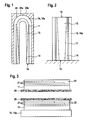
- FIG. 1 shows a schematic view of an embodiment of the method for producing a SOFC fuel cell 1, as in FIG. 5 is shown in perspective.
- FIG. 1 shows first a cross section through an injection mold having a first part mold 25a and a second part mold 25b.
- the partial molds 25a and 25b are movable relative to one another and can be moved apart for demolding an injection-molded electrolyte body 10.
- the electrolyte body 10 is formed as an electrolyte body closed at the end and therefore has a cap 24.
- the injection mold On the inside, the injection mold has an injection molding core 13, which is shown by way of example only as a hollow core in order to minimize the mass of the injection molding core 13 to be removed by burnout when the injection molding process has been completed.
- an interconnector material 14 is first applied to the injection molding core 13, wherein the underside has a large thickness, which decreases in the direction of the cap 24 of the electrolyte body 10.
- an inside electrode 11 is applied, which enters a direct connection with this when injecting an electrolyte mass 10.
- an electrolyte body 10 having an inside electrode 11 and an interconnector material 14 contacting the same is fabricated.
- the interconnector material 14 is already thicker at the second end 16 of the electrolyte body 10, since the subsequent contacting takes place at this end and thus a higher current density is taken into account.
- FIG. 2 11 shows schematic views of the structure of the coatings on a carrier foil 20, wherein the carrier foil 20 adjoins the inside electrode 11 in the upper illustration, whereas the carrier foil 20 according to the lower illustration is shown adjacent to layers 21 of interconnector material.
- the principle of film injection molding can be implemented, the film having the layer structure being applied to the injection molding core 13.
- the carrier film 20 is initially coated with the inside electrode 11 as shown in the upper illustration, with layers 21 of interconnector material subsequently being applied to the inside electrode 11.
- the layers 21 of the interconnector material are shown at different extents so that a free region 22 is formed, which is subsequently filled with a filling layer 23, for example glass-carbon layers 23.
- the electrolyte mass 10a is injected to form the electrolyte body 10, such that the electrolyte mass 10a can enter into a firm, cohesive connection with the inside electrode 11.
- the carrier film 20 may be filled flat, so that it can be wrapped around the cylindrical injection molding core 13. It is particularly advantageous if the carrier film 20 is preformed in the manner of a tube or sleeve, so that the casing or hose with the applied layers 11 and 21 or 23 can be slipped over the injection-molded core 13.
- the carrier foil 20 can also be removed by the removal of the injection-molded core 13 following the injection-molding step by means of a thermal process.
- an electrolyte body 10 results with an applied inside electrode 11 and an interconnector formed from layers 21.
- the filling layers 23 are provided at the locations which fill up the remaining layer thicknesses of the layers 21 in front of the interconnector material.
- FIG. 4 shows a development of a carrier film 20, which can already carry on the upper side an inner-side electrode (11, not shown).
- interconnector material 14 is applied, wherein the strips of interconnector material 14 preferably extend in the longitudinal direction of the interconnect material Electrolyte body 10 and thus extend in the longitudinal direction of the injection molding core 13.
- the FIG. 4 shows a development in a two-dimensional representation, wherein the carrier film 20 may preferably form a tubular shape with a circular cross-section. The strips of the interconnector material consequently run at regular intervals in the longitudinal direction of the electrolyte body 10.
- FIG. 5 shows a perspective view of a SOFC fuel cell 1.
- This has an electrolyte body 10, which forms the basic structure of the fuel cell 1 and the upper side is closed by a cap 24 to perform the SOFC fuel cell 1 as a closed end fuel cell.
- the SOFC fuel cell 1 is mounted on a base body 17, wherein at the same time contact elements 26 for contacting the inside electrode 11 and a contact element 27 for contacting the outside electrode 12 are shown.
- both inside interconnector material 14 is shown, which has a web structure 19, which is formed by the interconnector material 14 in strip form, as this in FIG. 4 is shown.
- the outside electrode 12 is shown with a ridge structure. Due to the closed design of the SOFC fuel cell 1, this has on the side of the main body 17 an opening 28 for the fuel gas flow.
- FIG. 6a shows an embodiment of an injection molding core 13, which is shown in cross-section and having grooves 18 distributed on the circumference.
- the grooves 18 can be filled with interconnector material 14, wherein the introduction of the interconnector material 14 in the grooves 18 can be done for example by means of a doctor blade process.
- FIG. 6c It is shown that after application of the interconnector material 14, the inside electrode 11 has been applied, for example, by a roll printing method or a screen printing method. That puts FIG.
- both the ceramic electrolyte body 10 and the respective coatings 11 and 14 may be baked and cured.
Abstract
Description
- Die vorliegende Erfindung betrifft ein Verfahren zur Herstellung einer SOFC Brennstoffzelle mit einem Elektrolytkörper in tubularer Bauform, wobei auf dem Elektrolytkörper wenigstens eine innenseitige Elektrode und eine außenseitige Elektrode aufgebracht wird.
- Festoxid-Brennstoffzellen, so genannte SOFC Brennstoffzellen (Solid Oxide Fuel Cells) mit keramischem Elektrolytkörper bilden eine Hochtemperatur-Variante von Brennstoffzellen. Sie werden bei 600°C bis 1.000°C betrieben und liefern dabei höchste elektrische Wirkungsgrade von bis etwa 50%. Grundsätzlich werden SOFC Brennstoffzellen in zwei Hauptvarianten unterteilt: Eine Variante bildet eine röhrenförmige, tubulare Form des Elektrolytkörpers, die gemäß einer weiteren Variante gegen eine flache, planare Form abzugrenzen ist. Dabei ist es notwendig, im Verfahren zur Herstellung einer SOFC-Brennstoffzelle gemäß der tubularen Variante die innenseitige und außenseitige Elektrode auf die Wandung des Elektrolytkörpers aufzubringen. Dazu ist bekannt, die auf der Innenseite des Elektrolytkörpers angeordnete Elektrode, meist ausgeführt als die Anode, die mit Brenngas umspült wird, als Beschichtung auf der Innenwand des Elektrolytkörpers aufzubringen. Der Elektrolytkörper wird dabei vorzugsweise extrudiert.
- Neben der Aufbringung der Elektroden auf den fertigen Elektrolytkörper werden zur Kontaktierung der Elektroden so genannte Interkonnektoren auf die Elektroden flächig aufgebracht, wobei die Aufbringung auf der Innenseite des Elektrolytkörpers häufig zu Problemen führt. Bekannt sind metallische Interkonnektoren, die aus einem hoch-chromhaltigen Werkstoff bestehen, um auf Grund der hohen Betriebstemperaturen eine hinreichende Korrosionsbeständigkeit kombiniert mit einer ausreichenden elektrischen Leitfähigkeit zu erhalten. Die im Betrieb der Brennstoffzelle entstehende Chromoxidschicht wirkt sich dabei negativ auf das Kathodenmaterial aus und kann zur vorzeitigen Alterung der Brennstoffzelle führen. Hingegen sind keramische Interkonnektoren zur elektrischen Kontaktierung der Elektroden zwar in der planaren Ausführung bekannt, finden für tubulare SOFC Brennstoffzellen bislang jedoch keine Anwendung. Auf Grund des großen Schlankheitsgrades der Elektrolytkörper ist die Aufbringung von keramischen Interkonnektoren auf der Innenwand des Elektrolytkörpers mit wesentlichen Problemen verbunden. Die Problematik ergibt sich insbesondere aus den geringen Wandstärken, da beispielsweise der Elektrolytkörper vorzugsweise eine Wandstärke von ca. 200 µm aufweist, wobei die poröse Anode auf der Innenseite des Elektrolytkörpers mit einer keramischen Interkonnektorschicht beschichtet werden muss. Aus Kostengründen müssen die Elektroden selbst ebenfalls dünn ausgeführt werden, die beispielsweise eine Dicke von 50 µm aufweisen. Darüber hinaus muss die Interkonnektorschicht ebenfalls hochporös sein, wobei eine über der Längserstreckung des Elektrolytkörpers sich ändernde Dicke des Interkonnektormaterials auf der Oberfläche des Elektrolytkörpers weitere Vorteile bietet.
- Es ist daher die Aufgabe der vorliegenden Erfindung, die voranstehend genannten Nachteile zur Herstellung einer SOFC Brennstoffzelle zu überwinden und ein Verfahren bereitzustellen, einen Elektrolytkörper sowie auf der Innen- und/oder Außenseite des Elektrolytkörpers notwendige Elektroden und entsprechende Interkonnektorschichten auf einfache Weise herzustellen.
- Diese Aufgabe wird ausgehend von einem Verfahren zur Herstellung einer SOFC Brennstoffzelle gemäß den Merkmalen des Anspruches 1 gelöst. Vorteilhafte Weiterbildungen der Erfindung sind in den abhängigen Ansprüchen angegeben.
- Die Erfindung schließt die technische Lehre ein, dass das Verfahren zur Herstellung einer SOFC - Brennstoffzelle wenigstens die Schritte des Bereitstellens eines Spritzgusskerns umfasst, auf dem wenigstens ein Interkonnektormaterial und die innenseitige Elektrode aufgebracht wird, wobei das Verfahren ferner das Anordnen des Spritzgusskerns in einer Spritzgussform, das Spritzgießen einer Elektrolytmasse zur Bildung des Elektrolytkörpers und das Entfernen des Spritzgusskerns nach Art eines Gussverfahrens mit verlorenem Kern umfasst.
- Die Erfindung geht dabei von dem Gedanken aus, dass zur Herstellung des Elektrolytkörpers ein Keramik-Spritzgussverfahren zur Anwendung kommt, wobei das Interkonnektormaterial und die innenseitige Elektrode schon im Spritzgussschritt derart angeordnet sind, dass dieses bzw. diese eine Verbindung mit dem Elektrolytkörper eingehen kann. Dabei wird ein Spritzgusskern in einer Spritzgussform zentrisch angeordnet, so dass sich ein rohrförmiger Hohlraum ergibt, in den die Elektrolytmasse eingespritzt wird, um den Elektrolytkörper zu bilden. Da sowohl das Interkonnektormaterial als auch die innenseitige Elektrode bereits auf dem Spritzgusskern aufgebracht sind, kann die Elektrolytmasse eine Verbindung mit der inneren Elektrode eingehen, so dass anschließend lediglich der Spritzgusskern aus dem Elektrolytkörper bzw. aus der innenseitigen Elektrode entfernt werden muss. Das Interkonnektormaterial wird vor dem Aufbringen des Materials zur Bildung der innenseitigen Elektrode auf den Spritzgusskern aufgebracht, so dass die Elektrolytmasse eine Verbindung mit dem Material der innenseitigen Elektrode eingehen kann.
- Mit Vorteil kann der Spritzgusskern mittels eines thermischen Verfahrens und vorzugsweise mittels einer Schmelzkerntechnik entfernt werden, wenn der Spritzguss des Elektrolytkörpers erfolgt ist. Das Prinzip, die formgebenden Komponenten beim Gießen eines Werkstückes zum Entformen zu zerstören, wird als Verfahren mit verlorenem Kern bezeichnet, welches vorliegend Anwendung finden kann. Das thermische Entfernen des Spritzgusskerns kann während eines Sintervorganges erfolgen, dem der Elektrolytkörper mit dem Interkonnektormaterial und der innenseitigen Elektrode nach dem Spritzgussverfahren zugeführt wird.
- Der Spritzgusskern kann vorteilhafterweise aus einem Kunststoffmaterial ausgebildet sein, wobei das thermische Verfahren zum Entfernen des Spritzgusskerns vorzugsweise durch ein Ausbrennen des Kunststoffmaterials aus dem Elektrolytkörper durchgeführt wird.
- Der Spritzgusskern kann mit einer konischen Außenkontur ausgebildet sein, so dass ein erstes Ende mit einem großen Durchmesser und ein zweites Ende mit einem kleinen Durchmesser des Spritzgusskerns gebildet ist, wobei das zweite Ende mit dem kleinen Durchmesser die Seite des Elektrolytkörpers darstellt, die das Aufnahmeende des tubularen Elektrolytkörpers auf einem Grundkörper bildet. Wird nun das Interkonnektormaterial und/oder die innenseitige Elektrode mittels eines Druckverfahrens, insbesondere mittels eines Rollendruckverfahrens oder eines Siebdruckverfahrens, auf den Spritzgusskern aufgebracht, so kann die Aufbringung derart erfolgen, dass sich nach Aufbringen des Interkonnektormaterials und des Materials der innenseitigen Elektrode ein zylinderförmiger Gesamtkörper ergibt. Dadurch wird ein Bereich des Interkonnektormaterials geschaffen, der eine größere Wandstärke aufweist, wobei dieser Bereich zur späteren elektrischen Kontaktierung der innenseitigen Elektrode dient, weil am Kontaktende des Interkonnektormaterials die höchste Stromdichte vorherrscht. Folglich kann die Dicke des Interkonnektormaterials der Stromdichte über der Länge des Elektrolytkörpers angepasst werden.
- Gemäß einer weiteren vorteilhaften Ausführungsform des erfindungsgemäßen Verfahrens wird das Interkonnektormaterial und/oder die innenseitige Elektrode auf einer Trägerfolie aufgebracht, die vor dem Spritzgießen der Elektrolytmasse auf dem Spritzgusskern angeordnet wird, so dass sich die Elektrolytmasse mit der innenseitigen Elektrode auf der Trägerfolie verbindet, wenn die Elektrolytmasse spritzgegossen wird.
- Vorteilhafterweise kann eine Aufbringung des Interkonnektormaterials in Schichten auf die Trägerfolie erfolgen, wobei erst anschließend die innenseitige Elektrode aufgebracht wird. Werden die Schichten des Interkonnektormaterials unterschiedlich weit über der Länge des Spritzgusskerns aufgebracht, so werden freie Bereiche gebildet, die mit Füllschichten, insbesondere mit Glaskohleschichten, aufgefüllt werden können. Durch viele übereinander aufgebrachte Schichten mit unterschiedlicher Breite entsteht ein Interkonnektor mit einer variablen Dicke, die in Richtung zur Kontaktierung des Interkonnektors zunimmt, da hier die Stromdichte am höchsten ist. Der Elektrolytkörper kann über einen Flansch auf einem Grundkörper aufgenommen sein, über den die Kontaktierung des Interkonnektors erfolgt. Folglich werden in der Richtung mehr Schichten von Interkonnektormaterial auf die Trägerfolie aufgebracht, die bei Fertigstellung der Brennstoffzelle in Richtung zum Flansch und folglich in Richtung zur Kontaktierung weist. Um die freien Bereiche, die durch eine geringere Anzahl von aufgebrachten Schichten entsteht, aufzufüllen, können Füllschichten, insbesondere Glaskohleschichten, auf der Trägerfolie aufgebracht werden. Da auf der Trägerfolie zunächst nicht über der gesamten Länge entsprechend der Länge des Spritzgusskerns Schichten von Interkonnektormaterial aufgebracht werden, werden die Füllschichten benachbart zu den einzelnen Schichten des Interkonnektormaterials aufgebracht. Folglich kann eine nächste Schicht von Interkonnektormaterial auch über einer Füllschicht aufgebracht werden. Ist die Aufbringung der Schichten aus Interkonnektormaterial beendet, wird anschließend das Material zur Bildung der innenseitigen Elektrode aufgebracht.
- Gemäß einer weiteren vorteilhaften Ausführungsform kann der Spritzgusskern Rillen aufweisen, in die das Interkonnektormaterial eingebracht wird, um eine Interkonnektorschicht zu bilden, die eine Struktur, vorzugsweise eine Stegstruktur oder eine Gitterstruktur, aufweist. Das Einbringen des Interkonnektormaterials in die Rillen der Spritzgussform kann beispielsweise mit einer Rakel erfolgen. Der Interkonnektor bildet folglich eine Matrixstruktur auf der Elektrode, um diese nicht vollständig zu überdecken. Vorteilhafterweise kann die Anzahl der Rillen über der Länge des Spritzgusskerns in der Struktur in einer Richtung erhöht werden, um in Richtung zur späteren Kontaktierung des Interkonnektors einen höheren Leitungsquerschnitt zu bilden, um der höheren Stromdichte gerecht zu werden.
- Das Interkonnektormaterial kann im Bereich des ersten Endes mit einer kleinen Dicke und im Bereich des zweiten Endes mit einer großen Dicke aufgebracht werden, so dass das Interkonnektormaterial eine konische Innenform aufweist und die konische Form des Spritzgusskerns vorzugsweise derart ausgleicht, dass das Interkonnektormaterial eine etwa zylindrische Außenform aufweist. Dabei können die Rillen im Spritzgusskern auch eine unterschiedliche Tiefe aufweisen, die in Richtung zur späteren Kontaktierung des Innterkonnektors zunimmt.
- Nach einem weiteren Verfahrensschritt kann nach dem Entformen des Elektrolytkörpers mit der innenseitigen Elektrode und dem Interkonnektormaterial die außenseitige Elektrode aufgebracht und nachfolgend vorzugsweise eingebrannt werden. Auch die außenseitige Elektrode kann mit einem Interkonnektormaterial versehen werden, das nach Entformen des Elektrolytkörpers aus der Spritzgussform aufgebracht werden kann, wobei die außenseitige Elektrode und ein außenseitig vorgesehener Interkonnektor auch auf gleiche Weise nach dem Prinzip der Folienhinterspritzung aufgebracht werden können, wie auf der Innenseite des Elektrolytkörpers. Insbesondere das Prinzip der Folienhinterspritzung kann sowohl aus Richtung des Spritzgusskerns als auch aus Richtung der Innenseite der Spritzgussform zum Spritzen des Elektrolytkörpers vorgesehen sein.
- Weitere, die Erfindung verbessernde Maßnahmen werden nachstehend gemeinsam mit der Beschreibung eines bevorzugten Ausführungsbeispieles der Erfindung anhand der Figuren näher dargestellt. Es zeigt:
- Figur 1
- eine schematische Ansicht eines Ausführungsbeispieles der vorliegenden Erfindung,
- Figur 2
- eine weitere Ansicht eines Ausführungsbeispieles der vorliegenden Erfindung mit einem konischen Spritzgusskern,
- Figur 3
- eine schematische Ansicht einer schichtweisen Aufbringung von Interkonnektormaterial auf einer Trägerfolie,
- Figur 4
- die schematische Ansicht einer Elektrode mit streifenförmig aufgebrachtem Interkonnektormaterial in einer Abwicklung,
- Figur 5
- eine perspektivische Ansicht eines Elektrolytkörpers mit einer innenseitigen und einer außenseitigen Elektrode sowie jeweils aufgebrachtem Interkonnektormaterial,
- Figur 6a
- ein Ausführungsbeispiel eines mit Rillen versehenen Spritzgusskerns,
- Figur 6b
- der Spritzgusskern gemäß
Figur 6a , wobei Interkonnektormaterial durch einen Rakelprozess in die Rillen des Spritzgusskerns eingebracht ist und - Figur 6c
- die Ansicht gemäß
Figur 6b , wobei Material zur Bildung einer innenseitigen Elektrode außenseitig auf den Spritzgusskern und dem eingebrachten Interkonnektormaterial aufgetragen ist. -
Figur 1 zeigt eine schematische Ansicht eines Ausführungsbeispiels des Verfahrens zur Herstellung einer SOFC Brennstoffzelle 1, wie diese inFigur 5 perspektivisch dargestellt ist.Figur 1 zeigt zunächst einen Querschnitt durch eine Spritzgussform, die eine erste Teilform 25a und eine zweite Teilform 25b aufweist. Die Teilformen 25a und 25b sind gegeneinander beweglich, und können zur Entformung eines spritzgegossenen Elektrolytkörpers 10 auseinander bewegt werden. Der Elektrolytkörper 10 ist als endseitig geschlossener Elektrolytkörper ausgebildet und weist daher eine Kappe 24 auf. Diese kann gemäß einer möglichen Ausführungsform zur Herstellung des Elektrolytkörpers 10 als ein Einzelteil ausgebildet sein, so dass der tubusartige, zylindrische Abschnitt des Elektrolytkörpers 10 durch Einspritzen einer Elektrolytmasse 10a in das Spritzgusswerkzeug hergestellt werden kann, wobei die Kappe 24 auch durch die Elektrolytmasse 10a selbst im Spritzguss hergestellt werden kann. Innenseitig weist die Spritzgussform einen Spritzgusskern 13 auf, der lediglich beispielhaft als Hohlkern dargestellt ist, um die durch ein Ausbrennen zu entfernende Masse des Spritzgusskernes 13 zu minimieren, wenn der Spritzgussprozess abgeschlossen ist. Außenseitig ist auf dem Spritzgusskern 13 zunächst ein Interkonnektormaterial 14 aufgebracht, wobei die Unterseite eine große Dicke aufweist, die in Richtung zur Kappe 24 des Elektrolytkörpers 10 abnimmt. Auf dem Interkonnektormaterial 14 ist eine innenseitige Elektrode 11 aufgebracht, die bei Einspritzen einer Elektrolytmasse 10 eine direkte Verbindung mit dieser eingeht. Wird der so gebildete Elektrolytkörper 10 aus der Spritzgussform entfernt und wird durch ein thermisches Verfahren der Spritzgusskern 13 aus der Innenseite des Elektrolytkörpers 10 vorzugsweise durch ein thermisches Verfahren entfernt, so ist ein Elektrolytkörper 10 mit einer innenseitigen Elektrode 11 und einem diese kontaktierenden Interkonnektormaterial 14 hergestellt. Gleichzeitig ist das Interkonnektormaterial 14 bereits am zweiten Ende 16 des Elektrolytkörpers 10 dicker, da an diesem Ende die spätere Kontaktierung stattfindet und somit einer höheren Stromdichte Rechnung getragen wird. -
Figur 2 zeigt schematische Ansichten des Aufbaues der Beschichtungen auf einer Trägerfolie 20, wobei die Trägerfolie 20 in der oberen Darstellung an die innenseitige Elektrode 11 angrenzt, wohingegen die Trägerfolie 20 gemäß der unteren Darstellung an Schichten 21 von Interkonnektormaterial angrenzend dargestellt ist. Damit kann das Prinzip der Folienhinterspritzung umgesetzt werden, wobei die Folie mit dem Schichtaufbau auf den Spritzgusskern 13 angewendet wird. - Die Trägerfolie 20 wird gemäß der oberen Darstellung zunächst mit der innenseitigen Elektrode 11 beschichtet, wobei anschließend Schichten 21 von Interkonnektormaterial auf die innenseitige Elektrode 11 aufgebracht werden. Die Schichten 21 des Interkonnektormaterials sind in unterschiedlicher Erstreckung gezeigt, so dass ein freier Bereich 22 entsteht, der anschließend mit einer Füllschicht 23, beispielsweise aus Glaskohleschichten 23, aufgefüllt wird. Anschließend wird die Elektrolytmasse 10a zur Bildung des Elektrolytkörpers 10 angespritzt, derart, dass die Elektrolytmasse 10a eine feste, stoffschlüssige Verbindung mit der innenseitigen Elektrode 11 eingehen kann.
- Die Trägerfolie 20 kann flächig ausgefüllt sein, so dass diese um den zylinderförmigen Spritzgusskern 13 herumgelegt werden kann. Besonders vorteilhaft ist es, wenn die Trägerfolie 20 hüllenartig oder schlauchartig vorgeformt ist, so dass die Hülle bzw. der Schlauch mit den aufgebrachten Schichten 11 und 21 bzw. 23 über den Spritzgusskern 13 gestülpt werden kann.
- Die Trägerfolie 20 kann durch das auf den Spritzgussschritt folgende Entfernen des Spritzgusskerns 13 mittels eines thermischen Verfahrens ebenfalls mit entfernt werden. Im Ergebnis ergibt sich ein Elektrolytkörper 10 mit einer aufgebrachten innenseitigen Elektrode 11 und einem aus Schichten 21 gebildeten Interkonnektor. Um eine zylindrische Gesamtform zu erhalten, sind die Füllschichten 23 an den Stellen vorgesehen, die die ausbleibenden Schichtdicken der Schichten 21 vor dem Interkonnektormaterial auffüllen.
-
Figur 4 zeigt eine Abwicklung einer Trägerfolie 20, die auf der Oberseite bereits eine innenseitige Elektrode (11, nicht dargestellt) tragen kann. In einer Streifenform ist Interkonnektormaterial 14 aufgetragen, wobei sich die Streifen des Interkonnektormaterials 14 vorzugsweise in Längsrichtung des Elektrolytkörpers 10 und damit in Längsrichtung des Spritzgusskerns 13 erstrecken. DieFigur 4 zeigt eine Abwicklung in einer flächigen Darstellung, wobei die Trägerfolie 20 vorzugsweise eine Schlauchform mit einem kreisförmigen Querschnitt bilden kann. Die Streifen des Interkonnektormaterials verlaufen folglich in regelmäßigen Abständen zueinander in Längsrichtung des Elektrolytkörpers 10. -
Figur 5 zeigt eine perspektivische Ansicht einer SOFC Brennstoffzelle 1. Diese weist einen Elektrolytkörper 10 auf, der die Grundstruktur der Brennstoffzelle 1 bildet und oberseitig durch eine Kappe 24 geschlossen ist, um die SOFC Brennstoffzelle 1 als endseitig geschlossene Brennstoffzelle auszuführen. Die SOFC Brennstoffzelle 1 ist auf einem Grundkörper 17 montiert, wobei zugleich Kontaktelemente 26 zur Kontaktierung der innenseitigen Elektrode 11 und ein Kontaktelement 27 zur Kontaktierung der außenseitigen Elektrode 12 gezeigt sind. Ferner ist sowohl innenseitig Interkonnektormaterial 14 gezeigt, die eine Stegstruktur 19 aufweist, die durch das Interkonnektormaterial 14 in Streifenform gebildet wird, wie dieses inFigur 4 dargestellt ist. Ebenfalls ist die außenseitige Elektrode 12 mit einer Stegstruktur gezeigt. Durch die geschlossene Bauweise der SOFC Brennstoffzelle 1 weist diese auf der Seite des Grundkörpers 17 eine Öffnung 28 für den Brenngaszustrom auf. -
Figur 6a zeigt ein Ausführungsbeispiel eines Spritzgusskerns 13, der im Querschnitt dargestellt ist und Rillen 18 auf dem Umfang gleich verteilt aufweist. GemäßFigur 6b ist erkennbar, dass die Rillen 18 mit Interkonnektormaterial 14 aufgefüllt werden können, wobei das Einbringen des Interkonnektormaterials 14 in die Rillen 18 beispielsweise mittels eines Rakelprozesses erfolgen kann. GemäßFigur 6c ist dargestellt, dass nach Aufbringen des Interkonnektormaterials 14 die innenseitige Elektrode 11 beispielsweise mit einem Rollendruckverfahren oder einem Siebdruckverfahren aufgebracht worden ist. Damit stelltFigur 6c einen Spritzgusskern 13 mit der jeweiligen Beschichtung dar, die ohne das Prinzip der Folienhinterspritzung und folglich ohne eine Trägerfolie 20 ein Spritzgießen von Elektrolytmasse 10a in ein Werkzeug ermöglicht, wobei die Elektrolytmasse 10a eine stoffschlüssige Verbindung mit der innenseitigen Elektrode 11 eingehen kann. In einem nachfolgenden Brennprozess können sowohl der keramische Elektrolytkörper 10 als auch die jeweiligen Beschichtungen 11 und 14 eingebrannt und gehärtet werden. - Die Erfindung beschränkt sich in ihrer Ausführung nicht auf das vorstehend angegebene bevorzugte Ausführungsbeispiel. Vielmehr ist eine Anzahl von Varianten denkbar, welche von der dargestellten Lösung auch bei grundsätzlich anders gearteten Ausführungen Gebrauch macht. Sämtliche aus den Ansprüchen, der Beschreibung oder den Zeichnungen hervorgehenden Merkmale und/oder Vorteile, einschließlich konstruktive Einzelheiten, räumliche Anordnungen und Verfahrensschritte, können sowohl für sich als auch in den verschiedensten Kombinationen erfindungswesentlich sein.
Claims (12)
- Verfahren zur Herstellung einer SOFC Brennstoffzelle (1), aufweisend einen Elektrolytkörper (10) mit einer tubularen Struktur, wobei auf dem tubularen Elektrolytkörper wenigstens eine innenseitige Elektrode (11) und eine außenseitige Elektrode (12) aufgebracht wird, wobei das Verfahren wenigstens die folgenden Schritte aufweist:- Bereitstellen eines Spritzgusskerns (13), auf dem wenigstens ein Interkonnektormaterial (14) und die innenseitige Elektrode (11) aufgebracht wird,- Anordnen des Spritzgusskerns (13) in einer Spritzgussform (25a, 25b),- Spritzgießen einer Elektrolytmasse (10a) zur Bildung des Elektrolytkörpers (10) und- Entfernen des Spritzgusskerns (13) nach Art eines Gussverfahrens mit verlorenem Kern.
- Verfahren nach Anspruch 1, dadurch gekennzeichnet, dass das Entfernen des Spritzgusskerns (13) mittels eines thermischen Verfahrens und vorzugsweise mittels einer Schmelzkerntechnik vorgenommen wird.
- Verfahren nach Anspruch 1 oder 2, dadurch gekennzeichnet, dass der Spritzgusskern (13) aus einem Kunststoffmaterial ausgebildet ist, wobei das thermische Verfahren zum Entfernen des Spritzgusskerns (13) vorzugsweise durch ein Ausbrennen des Kunststoffmaterials durchgeführt wird.
- Verfahren nach einem der Ansprüche 1 bis 3, dadurch gekennzeichnet, dass der Spritzgusskern (13) mit einer konischen Außenkontur ausgebildet ist, sodass ein erstes Ende (15) mit einem großen Durchmesser und ein zweites Ende (16) mit einem kleinen Durchmesser des Spritzgusskerns (13) gebildet ist, wobei das zweite Ende (16) mit dem kleinen Durchmesser das Aufnahmeende des tubularen Elektrolytkörpers (10) auf einem Grundkörper (17) bildet.
- Verfahren nach einem der vorgenannten Ansprüche, dadurch gekennzeichnet, dass das Interkonnektormaterial (14) und/oder die innenseitige Elektrode (11) mittels eines Druckverfahrens, insbesondere mittels eines Rollendruckverfahrens oder eines Siebdruckverfahrens, auf den Spritzgusskern (13) aufgebracht wird.
- Verfahren nach einem der Ansprüche 1 bis 4, dadurch gekennzeichnet, dass das Interkonnektormaterial (14) und/oder die innenseitige Elektrode (11) auf einer Trägerfolie (20) aufgebracht wird, die vor dem Spritzgießen der Elektrolytmasse (10a) auf dem Spritzgusskern (13) angeordnet wird, sodass sich die Elektrolytmasse (10a) mit der innenseitigen Elektrode (11) auf der Trägerfolie (20) verbindet, wenn die Elektrolytmasse (10a) spritzgegossen wird.
- Verfahren nach Anspruch 6, dadurch gekennzeichnet, dass eine Aufbringung des Interkonnektormaterials (14) in Schichten (21) auf die Trägerfolie (20) erfolgt und anschließend die innenseitige Elektrode (11) aufgebracht wird, wobei sich die Schichten (21) des Interkonnektormaterials (14) vorzugsweise in Längsrichtung unterschiedlich weit über der Länge der des Spritzgusskerns (13) erstrecken und freie Bereiche (22) bilden.
- Verfahren nach Anspruch 7, dadurch gekennzeichnet, dass die freien Bereiche (22) mit Füllschichten (23), insbesondere mit Glaskohleschichten (23) aufgefüllt werden.
- Verfahren nach einem der vorgenannten Ansprüche, dadurch gekennzeichnet, dass der Spritzgusskern (13) Rillen (18) aufweist, in die das Interkonnektormaterial (14) eingebracht wird, um eine Interkonnektorschicht (14) zu bilden, die eine Struktur, vorzugsweise eine Stegstruktur (19) oder eine Gitterstruktur, aufweist.
- Verfahren nach einem der vorgenannten Ansprüche, dadurch gekennzeichnet, dass das Interkonnektormaterial (14) im Bereich des ersten Endes (15) mit einer kleinen Dicke und im Bereich des zweiten Endes (15) mit einer großen Dicke aufgebracht wird, sodass das Interkonnektormaterial (14) eine konische Innenform aufweist und die konische Form des Spritzgusskerns (13) vorzugsweise derart ausgleicht, dass das Interkonnektormaterial (14) eine etwa zylindrische Außenform aufweist.
- Verfahren nach einem der vorgenannten Ansprüche, dadurch gekennzeichnet, dass nach dem Entformen des Elektrolytkörpers (10) mit der innenseitigen Elektrode (11) und dem Interkonnektormaterial (14) die außenseitige Elektrode (12) aufgebracht und nachfolgend vorzugsweise eingebrannt wird.
- SOFC Brennstoffzelle (1) hergestellt mit einem Verfahren nach einem der Ansprüche 1 bis 11.
Applications Claiming Priority (1)
| Application Number | Priority Date | Filing Date | Title |
|---|---|---|---|
| DE102010001005A DE102010001005A1 (de) | 2010-01-19 | 2010-01-19 | Verfahren zur Herstellung einer SOFC Brennstoffzelle |
Publications (2)
| Publication Number | Publication Date |
|---|---|
| EP2357704A1 true EP2357704A1 (de) | 2011-08-17 |
| EP2357704B1 EP2357704B1 (de) | 2014-03-12 |
Family
ID=43759446
Family Applications (1)
| Application Number | Title | Priority Date | Filing Date |
|---|---|---|---|
| EP11151074.9A Not-in-force EP2357704B1 (de) | 2010-01-19 | 2011-01-17 | Verfahren zur Herstellung einer SOFC Brennstoffzelle |
Country Status (4)
| Country | Link |
|---|---|
| US (1) | US8574791B2 (de) |
| EP (1) | EP2357704B1 (de) |
| DE (1) | DE102010001005A1 (de) |
| RU (1) | RU2555747C2 (de) |
Cited By (2)
| Publication number | Priority date | Publication date | Assignee | Title |
|---|---|---|---|---|
| WO2014128292A1 (de) * | 2013-02-25 | 2014-08-28 | Robert Bosch Gmbh | Tubulare festoxidzelle |
| CN107611464A (zh) * | 2017-10-24 | 2018-01-19 | 中国矿业大学(北京) | 一种可插拔式固体氧化物燃料电池堆结构 |
Families Citing this family (25)
| Publication number | Priority date | Publication date | Assignee | Title |
|---|---|---|---|---|
| US9457768B2 (en) | 2011-04-21 | 2016-10-04 | Pylon Manufacturing Corp. | Vortex damping wiper blade |
| TWI472090B (zh) * | 2011-04-22 | 2015-02-01 | Univ Nat Cheng Kung | Fuel cell solid electrolyte structure |
| CA2843527C (en) | 2011-07-28 | 2018-11-27 | Pylon Manufacturing Corp. | Windshield wiper adapter, connector and assembly |
| US9108595B2 (en) | 2011-07-29 | 2015-08-18 | Pylon Manufacturing Corporation | Windshield wiper connector |
| DE102011081545A1 (de) * | 2011-08-25 | 2013-02-28 | Robert Bosch Gmbh | Inert geträgerte tubulare Brennstoffzelle |
| DE102011087425A1 (de) * | 2011-11-30 | 2013-06-06 | Robert Bosch Gmbh | Herstellungsverfahren für eine tubulare Brennstoffzelle |
| DE102012221417A1 (de) * | 2011-11-30 | 2013-06-06 | Robert Bosch Gmbh | Tubulare Metall-Luft-Zelle |
| DE102011087430A1 (de) * | 2011-11-30 | 2013-06-06 | Robert Bosch Gmbh | Tubulare Brennstoffzelle mit Stabilisationsstegen |
| GB2498055B (en) * | 2011-11-30 | 2018-03-07 | Bosch Gmbh Robert | Fuel cell system |
| DE102011087422A1 (de) * | 2011-11-30 | 2013-06-06 | Robert Bosch Gmbh | Herstellungsverfahren für eine tubulare Brennstoffzelle |
| RU2577981C1 (ru) | 2012-02-24 | 2016-03-20 | Пилон Мануфэкчуринг Корп. | Щетка стеклоочистителя |
| US10723322B2 (en) | 2012-02-24 | 2020-07-28 | Pylon Manufacturing Corp. | Wiper blade with cover |
| US20130219649A1 (en) | 2012-02-24 | 2013-08-29 | Pylon Manufacturing Corp. | Wiper blade |
| US10829092B2 (en) | 2012-09-24 | 2020-11-10 | Pylon Manufacturing Corp. | Wiper blade with modular mounting base |
| DE102012221419A1 (de) | 2012-11-23 | 2014-05-28 | Robert Bosch Gmbh | Tubulare Elektrolysezelle |
| US10166951B2 (en) | 2013-03-15 | 2019-01-01 | Pylon Manufacturing Corp. | Windshield wiper connector |
| US9505380B2 (en) | 2014-03-07 | 2016-11-29 | Pylon Manufacturing Corp. | Windshield wiper connector and assembly |
| DE102014005252A1 (de) * | 2014-04-10 | 2015-10-15 | Hans-Jürgen Bohe | Galvanische Zelle und Redox-Flow-Zelle |
| US10363905B2 (en) | 2015-10-26 | 2019-07-30 | Pylon Manufacturing Corp. | Wiper blade |
| US10513246B2 (en) | 2016-05-19 | 2019-12-24 | Pylon Manufacturing Corp. | Windshield wiper connector |
| WO2017201458A1 (en) | 2016-05-19 | 2017-11-23 | Pylon Manufacturing Corp. | Windshield wiper connector |
| CN109311451B (zh) | 2016-05-19 | 2022-08-23 | 电缆塔制造有限公司 | 挡风玻璃雨刮器片 |
| CN109311450A (zh) | 2016-05-19 | 2019-02-05 | 电缆塔制造有限公司 | 挡风玻璃雨刮器连接器 |
| US11040705B2 (en) | 2016-05-19 | 2021-06-22 | Pylon Manufacturing Corp. | Windshield wiper connector |
| JP2021169387A (ja) * | 2020-04-15 | 2021-10-28 | セイコーエプソン株式会社 | 固体組成物の製造方法および機能性セラミックス成形体の製造方法 |
Citations (2)
| Publication number | Priority date | Publication date | Assignee | Title |
|---|---|---|---|---|
| EP0932214A2 (de) * | 1998-01-22 | 1999-07-28 | Litton Systems, Inc. | Modular elektrochemische Vorrichtung aus keramischem Material und sein Herstellungverfahren |
| DE60123840T2 (de) * | 2001-01-26 | 2007-05-16 | L'Air Liquide, S.A. pour l'Etude et l'Exploitation des Procédés Georges Claude | Gestapelte mikrostrukturen leitender, keramischer oxidionenmembranen; verwendung zur hochdrucksauerstoffproduktion |
Family Cites Families (7)
| Publication number | Priority date | Publication date | Assignee | Title |
|---|---|---|---|---|
| SU1653433A1 (ru) * | 1989-05-16 | 1995-09-27 | Институт электрохимии УО АН СССР | Твердый электролит с рубидий-катионной проводимостью |
| US6383350B1 (en) * | 2000-07-26 | 2002-05-07 | Northrop Grumman Corporation | Thin film modular electrochemical apparatus and method of manufacture therefor |
| US6936366B2 (en) * | 2002-04-03 | 2005-08-30 | Hewlett-Packard Development Company, L.P. | Single chamber solid oxide fuel cell architecture for high temperature operation |
| US6998187B2 (en) * | 2003-08-07 | 2006-02-14 | Nanodynamics, Inc. | Solid oxide fuel cells with novel internal geometry |
| RU2310952C2 (ru) * | 2005-12-16 | 2007-11-20 | Общество с ограниченной ответственностью "Национальная инновационная компания "Новые энергетические проекты" | Трубчатый элемент (его варианты), батарея трубчатых элементов с токопроходом по образующей и способ его изготовления |
| RU2310256C2 (ru) * | 2005-12-16 | 2007-11-10 | Общество с ограниченной ответственностью "Национальная инновационная компания "Новые энергетические проекты" | Трубчатый элемент (варианты) для батарей высокотемпературных электрохимических устройств с тонкослойным твердым электролитом и способ его изготовления |
| US20110294041A1 (en) * | 2008-12-12 | 2011-12-01 | Sascha Kuehn | Solid oxide fuel cell with special cell geometry |
-
2010
- 2010-01-19 DE DE102010001005A patent/DE102010001005A1/de not_active Withdrawn
-
2011
- 2011-01-17 EP EP11151074.9A patent/EP2357704B1/de not_active Not-in-force
- 2011-01-18 RU RU2011101640/07A patent/RU2555747C2/ru not_active IP Right Cessation
- 2011-01-19 US US13/009,347 patent/US8574791B2/en not_active Expired - Fee Related
Patent Citations (2)
| Publication number | Priority date | Publication date | Assignee | Title |
|---|---|---|---|---|
| EP0932214A2 (de) * | 1998-01-22 | 1999-07-28 | Litton Systems, Inc. | Modular elektrochemische Vorrichtung aus keramischem Material und sein Herstellungverfahren |
| DE60123840T2 (de) * | 2001-01-26 | 2007-05-16 | L'Air Liquide, S.A. pour l'Etude et l'Exploitation des Procédés Georges Claude | Gestapelte mikrostrukturen leitender, keramischer oxidionenmembranen; verwendung zur hochdrucksauerstoffproduktion |
Non-Patent Citations (1)
| Title |
|---|
| N. STELZER, R. ZAUNER, W. GRIENAUER, L. BACA, U.A.: "Miniaturisierte keramische Hochtemperatur Brennstoffzellen Komponenten", 24 January 2007 (2007-01-24), pages 1 - 64, XP002630265, Retrieved from the Internet <URL:http://www.fabrikderzukunft.at/nw_pdf/0669_brennstoffzellen.pdf> [retrieved on 20110328] * |
Cited By (2)
| Publication number | Priority date | Publication date | Assignee | Title |
|---|---|---|---|---|
| WO2014128292A1 (de) * | 2013-02-25 | 2014-08-28 | Robert Bosch Gmbh | Tubulare festoxidzelle |
| CN107611464A (zh) * | 2017-10-24 | 2018-01-19 | 中国矿业大学(北京) | 一种可插拔式固体氧化物燃料电池堆结构 |
Also Published As
| Publication number | Publication date |
|---|---|
| EP2357704B1 (de) | 2014-03-12 |
| US8574791B2 (en) | 2013-11-05 |
| US20110177434A1 (en) | 2011-07-21 |
| DE102010001005A1 (de) | 2011-07-21 |
| RU2011101640A (ru) | 2012-07-27 |
| RU2555747C2 (ru) | 2015-07-10 |
Similar Documents
| Publication | Publication Date | Title |
|---|---|---|
| EP2357704B1 (de) | Verfahren zur Herstellung einer SOFC Brennstoffzelle | |
| DE2544225C2 (de) | Verfahren zur Herstellung eines Wickelkondensators mit mindestens zwei Kapazitäten | |
| DE102013108413B4 (de) | Verfahren zum Herstellen eines Brennstoffzellenstapels sowie Brennstoffzellenstapel und Brennstoffzelle/Elektrolyseur | |
| DE102010001988A1 (de) | Verfahren zur Herstellung einer elektrolytgetragenen SOFC-Brennstoffzelle | |
| EP1533571B1 (de) | Verfahren zum Herstellen von keramischen Glühkerzen | |
| EP2777083B1 (de) | Verfahren zum elektrischen kontaktieren eines elektronischen bauelements als stapel und elektronisches bauelement mit einer kontaktierungsstruktur | |
| DE102015105568A1 (de) | Additive Fertigung für Brennstoffzellenströmungsfelder | |
| DE60307277T2 (de) | Anodengestützte brennstoffzelle | |
| DE10151134A1 (de) | Diffusionsschicht für eine Brennstoffzelle und ein Verfahren und Vorrichtung zur Herstellung derselben | |
| DE102004026572A1 (de) | Herstellungsverfahren für piezoelektrisches Schichtelement | |
| DE3732037A1 (de) | Dichte bleibatterie und verfahren zu deren herstellung | |
| DE3625959C2 (de) | ||
| EP2483198A2 (de) | Dreidimensionale mikro-struktur, anordnung mit mindestens zwei dreidimensionalen mikro-strukturen, verfahren zum herstellen der mikro-struktur und verwendung der mikro-struktur | |
| DE3320557A1 (de) | Verfahren zur herstellung einer raketenbrennkammer und raketenbrennkammer | |
| EP1500159B1 (de) | Schmelzkarbonatbrennstoffzelle und verfahren zur herstellung einer solchen | |
| WO2021122169A1 (de) | Verfahren zum herstellen einer dichtung für eine elektrochemische einheit einer elektrochemischen vorrichtung und baugruppe für eine elektrochemische vorrichtung | |
| WO2000073046A1 (de) | Keramischer wabenkörper mit einlagerung | |
| DE10056535A1 (de) | Brennstoffzellenanordnung und Verfahren zur Herstellung einer solchen | |
| DE1267738B (de) | Verfahren zur Herstellung von elektrischen Verbindungen zwischen den Stromkreisen von mehrlagigen gedruckten elektrischen Schaltungen | |
| WO2012059380A1 (de) | Aktoreinheit, verfahren zur fertigung einer aktoreinheit und hülse zur aufnahme eines piezoaktors | |
| DE102013100764B4 (de) | Verfahren zur Herstellung von durch physikalische Gasphasenabscheidung erzeugten Elektroden sowie ein Verfahren zur Herstellung von Piezoelementen mit durch physikalische Gasphasenabscheidung erzeugten Elektroden | |
| DE102008009826A1 (de) | Vorrichtung zur Bestimmung eines elektrophysiologischen Parameters von biologischem Zellmaterial, Verfahren zur Herstellung einer Messelektrode für eine derartige Vorrichtung sowie Verfahren zur Vermessung einer Zelle mithilfe einer derartigen Vorrichtung | |
| WO2018019586A1 (de) | Verfahren zur herstellung eines stromsammlers für eine brennstoffzelle und brennstoffzelle | |
| DE4213728A1 (de) | Brennstoffzellenanordnung und Verfahren zur Herstellung eines dafür geeigneten Festkörperelektrolyten | |
| DE102021119986A1 (de) | Verfahren und Vorrichtung zur Isolationsbeschichtung eines Stators |
Legal Events
| Date | Code | Title | Description |
|---|---|---|---|
| PUAI | Public reference made under article 153(3) epc to a published international application that has entered the european phase |
Free format text: ORIGINAL CODE: 0009012 |
|
| AK | Designated contracting states |
Kind code of ref document: A1 Designated state(s): AL AT BE BG CH CY CZ DE DK EE ES FI FR GB GR HR HU IE IS IT LI LT LU LV MC MK MT NL NO PL PT RO RS SE SI SK SM TR |
|
| AX | Request for extension of the european patent |
Extension state: BA ME |
|
| 17P | Request for examination filed |
Effective date: 20120217 |
|
| 17Q | First examination report despatched |
Effective date: 20130506 |
|
| GRAP | Despatch of communication of intention to grant a patent |
Free format text: ORIGINAL CODE: EPIDOSNIGR1 |
|
| RIC1 | Information provided on ipc code assigned before grant |
Ipc: B28B 1/24 20060101ALI20130715BHEP Ipc: B28B 7/34 20060101ALI20130715BHEP Ipc: H01M 8/12 20060101AFI20130715BHEP Ipc: B29C 45/26 20060101ALI20130715BHEP Ipc: H01M 8/00 20060101ALI20130715BHEP |
|
| INTG | Intention to grant announced |
Effective date: 20130814 |
|
| GRAS | Grant fee paid |
Free format text: ORIGINAL CODE: EPIDOSNIGR3 |
|
| GRAA | (expected) grant |
Free format text: ORIGINAL CODE: 0009210 |
|
| AK | Designated contracting states |
Kind code of ref document: B1 Designated state(s): AL AT BE BG CH CY CZ DE DK EE ES FI FR GB GR HR HU IE IS IT LI LT LU LV MC MK MT NL NO PL PT RO RS SE SI SK SM TR |
|
| REG | Reference to a national code |
Ref country code: GB Ref legal event code: FG4D Free format text: NOT ENGLISH |
|
| REG | Reference to a national code |
Ref country code: CH Ref legal event code: EP |
|
| REG | Reference to a national code |
Ref country code: AT Ref legal event code: REF Ref document number: 656819 Country of ref document: AT Kind code of ref document: T Effective date: 20140315 |
|
| REG | Reference to a national code |
Ref country code: IE Ref legal event code: FG4D Free format text: LANGUAGE OF EP DOCUMENT: GERMAN |
|
| REG | Reference to a national code |
Ref country code: DE Ref legal event code: R096 Ref document number: 502011002340 Country of ref document: DE Effective date: 20140424 |
|
| REG | Reference to a national code |
Ref country code: NL Ref legal event code: T3 |
|
| PG25 | Lapsed in a contracting state [announced via postgrant information from national office to epo] |
Ref country code: NO Free format text: LAPSE BECAUSE OF FAILURE TO SUBMIT A TRANSLATION OF THE DESCRIPTION OR TO PAY THE FEE WITHIN THE PRESCRIBED TIME-LIMIT Effective date: 20140612 Ref country code: LT Free format text: LAPSE BECAUSE OF FAILURE TO SUBMIT A TRANSLATION OF THE DESCRIPTION OR TO PAY THE FEE WITHIN THE PRESCRIBED TIME-LIMIT Effective date: 20140312 |
|
| REG | Reference to a national code |
Ref country code: LT Ref legal event code: MG4D |
|
| PG25 | Lapsed in a contracting state [announced via postgrant information from national office to epo] |
Ref country code: CY Free format text: LAPSE BECAUSE OF FAILURE TO SUBMIT A TRANSLATION OF THE DESCRIPTION OR TO PAY THE FEE WITHIN THE PRESCRIBED TIME-LIMIT Effective date: 20140312 Ref country code: FI Free format text: LAPSE BECAUSE OF FAILURE TO SUBMIT A TRANSLATION OF THE DESCRIPTION OR TO PAY THE FEE WITHIN THE PRESCRIBED TIME-LIMIT Effective date: 20140312 Ref country code: SE Free format text: LAPSE BECAUSE OF FAILURE TO SUBMIT A TRANSLATION OF THE DESCRIPTION OR TO PAY THE FEE WITHIN THE PRESCRIBED TIME-LIMIT Effective date: 20140312 |
|
| PG25 | Lapsed in a contracting state [announced via postgrant information from national office to epo] |
Ref country code: LV Free format text: LAPSE BECAUSE OF FAILURE TO SUBMIT A TRANSLATION OF THE DESCRIPTION OR TO PAY THE FEE WITHIN THE PRESCRIBED TIME-LIMIT Effective date: 20140312 Ref country code: RS Free format text: LAPSE BECAUSE OF FAILURE TO SUBMIT A TRANSLATION OF THE DESCRIPTION OR TO PAY THE FEE WITHIN THE PRESCRIBED TIME-LIMIT Effective date: 20140312 Ref country code: HR Free format text: LAPSE BECAUSE OF FAILURE TO SUBMIT A TRANSLATION OF THE DESCRIPTION OR TO PAY THE FEE WITHIN THE PRESCRIBED TIME-LIMIT Effective date: 20140312 |
|
| PG25 | Lapsed in a contracting state [announced via postgrant information from national office to epo] |
Ref country code: IS Free format text: LAPSE BECAUSE OF FAILURE TO SUBMIT A TRANSLATION OF THE DESCRIPTION OR TO PAY THE FEE WITHIN THE PRESCRIBED TIME-LIMIT Effective date: 20140712 Ref country code: CZ Free format text: LAPSE BECAUSE OF FAILURE TO SUBMIT A TRANSLATION OF THE DESCRIPTION OR TO PAY THE FEE WITHIN THE PRESCRIBED TIME-LIMIT Effective date: 20140312 Ref country code: RO Free format text: LAPSE BECAUSE OF FAILURE TO SUBMIT A TRANSLATION OF THE DESCRIPTION OR TO PAY THE FEE WITHIN THE PRESCRIBED TIME-LIMIT Effective date: 20140312 Ref country code: BG Free format text: LAPSE BECAUSE OF FAILURE TO SUBMIT A TRANSLATION OF THE DESCRIPTION OR TO PAY THE FEE WITHIN THE PRESCRIBED TIME-LIMIT Effective date: 20140612 Ref country code: EE Free format text: LAPSE BECAUSE OF FAILURE TO SUBMIT A TRANSLATION OF THE DESCRIPTION OR TO PAY THE FEE WITHIN THE PRESCRIBED TIME-LIMIT Effective date: 20140312 |
|
| PG25 | Lapsed in a contracting state [announced via postgrant information from national office to epo] |
Ref country code: ES Free format text: LAPSE BECAUSE OF FAILURE TO SUBMIT A TRANSLATION OF THE DESCRIPTION OR TO PAY THE FEE WITHIN THE PRESCRIBED TIME-LIMIT Effective date: 20140312 Ref country code: PL Free format text: LAPSE BECAUSE OF FAILURE TO SUBMIT A TRANSLATION OF THE DESCRIPTION OR TO PAY THE FEE WITHIN THE PRESCRIBED TIME-LIMIT Effective date: 20140312 Ref country code: SK Free format text: LAPSE BECAUSE OF FAILURE TO SUBMIT A TRANSLATION OF THE DESCRIPTION OR TO PAY THE FEE WITHIN THE PRESCRIBED TIME-LIMIT Effective date: 20140312 |
|
| REG | Reference to a national code |
Ref country code: DE Ref legal event code: R097 Ref document number: 502011002340 Country of ref document: DE |
|
| PG25 | Lapsed in a contracting state [announced via postgrant information from national office to epo] |
Ref country code: PT Free format text: LAPSE BECAUSE OF FAILURE TO SUBMIT A TRANSLATION OF THE DESCRIPTION OR TO PAY THE FEE WITHIN THE PRESCRIBED TIME-LIMIT Effective date: 20140714 |
|
| PLBE | No opposition filed within time limit |
Free format text: ORIGINAL CODE: 0009261 |
|
| STAA | Information on the status of an ep patent application or granted ep patent |
Free format text: STATUS: NO OPPOSITION FILED WITHIN TIME LIMIT |
|
| PG25 | Lapsed in a contracting state [announced via postgrant information from national office to epo] |
Ref country code: DK Free format text: LAPSE BECAUSE OF FAILURE TO SUBMIT A TRANSLATION OF THE DESCRIPTION OR TO PAY THE FEE WITHIN THE PRESCRIBED TIME-LIMIT Effective date: 20140312 |
|
| 26N | No opposition filed |
Effective date: 20141215 |
|
| PG25 | Lapsed in a contracting state [announced via postgrant information from national office to epo] |
Ref country code: RS Free format text: LAPSE BECAUSE OF FAILURE TO SUBMIT A TRANSLATION OF THE DESCRIPTION OR TO PAY THE FEE WITHIN THE PRESCRIBED TIME-LIMIT Effective date: 20140903 |
|
| REG | Reference to a national code |
Ref country code: DE Ref legal event code: R097 Ref document number: 502011002340 Country of ref document: DE Effective date: 20141215 |
|
| PG25 | Lapsed in a contracting state [announced via postgrant information from national office to epo] |
Ref country code: IT Free format text: LAPSE BECAUSE OF FAILURE TO SUBMIT A TRANSLATION OF THE DESCRIPTION OR TO PAY THE FEE WITHIN THE PRESCRIBED TIME-LIMIT Effective date: 20140312 |
|
| PG25 | Lapsed in a contracting state [announced via postgrant information from national office to epo] |
Ref country code: BE Free format text: LAPSE BECAUSE OF NON-PAYMENT OF DUE FEES Effective date: 20150131 |
|
| PG25 | Lapsed in a contracting state [announced via postgrant information from national office to epo] |
Ref country code: SI Free format text: LAPSE BECAUSE OF FAILURE TO SUBMIT A TRANSLATION OF THE DESCRIPTION OR TO PAY THE FEE WITHIN THE PRESCRIBED TIME-LIMIT Effective date: 20140312 |
|
| REG | Reference to a national code |
Ref country code: CH Ref legal event code: PL |
|
| PG25 | Lapsed in a contracting state [announced via postgrant information from national office to epo] |
Ref country code: LU Free format text: LAPSE BECAUSE OF FAILURE TO SUBMIT A TRANSLATION OF THE DESCRIPTION OR TO PAY THE FEE WITHIN THE PRESCRIBED TIME-LIMIT Effective date: 20150117 |
|
| PG25 | Lapsed in a contracting state [announced via postgrant information from national office to epo] |
Ref country code: MC Free format text: LAPSE BECAUSE OF FAILURE TO SUBMIT A TRANSLATION OF THE DESCRIPTION OR TO PAY THE FEE WITHIN THE PRESCRIBED TIME-LIMIT Effective date: 20140312 |
|
| PG25 | Lapsed in a contracting state [announced via postgrant information from national office to epo] |
Ref country code: CH Free format text: LAPSE BECAUSE OF NON-PAYMENT OF DUE FEES Effective date: 20150131 Ref country code: LI Free format text: LAPSE BECAUSE OF NON-PAYMENT OF DUE FEES Effective date: 20150131 |
|
| REG | Reference to a national code |
Ref country code: IE Ref legal event code: MM4A |
|
| REG | Reference to a national code |
Ref country code: FR Ref legal event code: PLFP Year of fee payment: 6 |
|
| PG25 | Lapsed in a contracting state [announced via postgrant information from national office to epo] |
Ref country code: IE Free format text: LAPSE BECAUSE OF NON-PAYMENT OF DUE FEES Effective date: 20150117 |
|
| PG25 | Lapsed in a contracting state [announced via postgrant information from national office to epo] |
Ref country code: GR Free format text: LAPSE BECAUSE OF FAILURE TO SUBMIT A TRANSLATION OF THE DESCRIPTION OR TO PAY THE FEE WITHIN THE PRESCRIBED TIME-LIMIT Effective date: 20140613 |
|
| PG25 | Lapsed in a contracting state [announced via postgrant information from national office to epo] |
Ref country code: MT Free format text: LAPSE BECAUSE OF FAILURE TO SUBMIT A TRANSLATION OF THE DESCRIPTION OR TO PAY THE FEE WITHIN THE PRESCRIBED TIME-LIMIT Effective date: 20140312 |
|
| REG | Reference to a national code |
Ref country code: FR Ref legal event code: PLFP Year of fee payment: 7 |
|
| REG | Reference to a national code |
Ref country code: AT Ref legal event code: MM01 Ref document number: 656819 Country of ref document: AT Kind code of ref document: T Effective date: 20160117 |
|
| PG25 | Lapsed in a contracting state [announced via postgrant information from national office to epo] |
Ref country code: HU Free format text: LAPSE BECAUSE OF FAILURE TO SUBMIT A TRANSLATION OF THE DESCRIPTION OR TO PAY THE FEE WITHIN THE PRESCRIBED TIME-LIMIT; INVALID AB INITIO Effective date: 20110117 Ref country code: SM Free format text: LAPSE BECAUSE OF FAILURE TO SUBMIT A TRANSLATION OF THE DESCRIPTION OR TO PAY THE FEE WITHIN THE PRESCRIBED TIME-LIMIT Effective date: 20140312 Ref country code: AT Free format text: LAPSE BECAUSE OF NON-PAYMENT OF DUE FEES Effective date: 20160117 |
|
| PG25 | Lapsed in a contracting state [announced via postgrant information from national office to epo] |
Ref country code: TR Free format text: LAPSE BECAUSE OF FAILURE TO SUBMIT A TRANSLATION OF THE DESCRIPTION OR TO PAY THE FEE WITHIN THE PRESCRIBED TIME-LIMIT Effective date: 20140312 |
|
| REG | Reference to a national code |
Ref country code: FR Ref legal event code: PLFP Year of fee payment: 8 |
|
| PG25 | Lapsed in a contracting state [announced via postgrant information from national office to epo] |
Ref country code: MK Free format text: LAPSE BECAUSE OF FAILURE TO SUBMIT A TRANSLATION OF THE DESCRIPTION OR TO PAY THE FEE WITHIN THE PRESCRIBED TIME-LIMIT Effective date: 20140312 |
|
| PG25 | Lapsed in a contracting state [announced via postgrant information from national office to epo] |
Ref country code: AL Free format text: LAPSE BECAUSE OF FAILURE TO SUBMIT A TRANSLATION OF THE DESCRIPTION OR TO PAY THE FEE WITHIN THE PRESCRIBED TIME-LIMIT Effective date: 20140312 |
|
| PGFP | Annual fee paid to national office [announced via postgrant information from national office to epo] |
Ref country code: NL Payment date: 20200122 Year of fee payment: 10 Ref country code: GB Payment date: 20200127 Year of fee payment: 10 Ref country code: DE Payment date: 20200324 Year of fee payment: 10 |
|
| PGFP | Annual fee paid to national office [announced via postgrant information from national office to epo] |
Ref country code: FR Payment date: 20200123 Year of fee payment: 10 |
|
| REG | Reference to a national code |
Ref country code: DE Ref legal event code: R119 Ref document number: 502011002340 Country of ref document: DE |
|
| REG | Reference to a national code |
Ref country code: NL Ref legal event code: MM Effective date: 20210201 |
|
| GBPC | Gb: european patent ceased through non-payment of renewal fee |
Effective date: 20210117 |
|
| PG25 | Lapsed in a contracting state [announced via postgrant information from national office to epo] |
Ref country code: NL Free format text: LAPSE BECAUSE OF NON-PAYMENT OF DUE FEES Effective date: 20210201 Ref country code: FR Free format text: LAPSE BECAUSE OF NON-PAYMENT OF DUE FEES Effective date: 20210131 |
|
| PG25 | Lapsed in a contracting state [announced via postgrant information from national office to epo] |
Ref country code: GB Free format text: LAPSE BECAUSE OF NON-PAYMENT OF DUE FEES Effective date: 20210117 Ref country code: DE Free format text: LAPSE BECAUSE OF NON-PAYMENT OF DUE FEES Effective date: 20210803 |