EP2355709B1 - Spatial array of sensors mounted on a tool - Google Patents
Spatial array of sensors mounted on a tool Download PDFInfo
- Publication number
- EP2355709B1 EP2355709B1 EP09765212.7A EP09765212A EP2355709B1 EP 2355709 B1 EP2355709 B1 EP 2355709B1 EP 09765212 A EP09765212 A EP 09765212A EP 2355709 B1 EP2355709 B1 EP 2355709B1
- Authority
- EP
- European Patent Office
- Prior art keywords
- tool
- sensors
- information
- array
- processing device
- Prior art date
- Legal status (The legal status is an assumption and is not a legal conclusion. Google has not performed a legal analysis and makes no representation as to the accuracy of the status listed.)
- Not-in-force
Links
- 238000012545 processing Methods 0.000 claims description 36
- 210000004204 blood vessel Anatomy 0.000 claims description 14
- 230000000694 effects Effects 0.000 claims description 14
- 238000000034 method Methods 0.000 claims description 12
- 239000000758 substrate Substances 0.000 claims description 9
- 230000008569 process Effects 0.000 claims description 8
- 230000017531 blood circulation Effects 0.000 claims description 5
- 239000008280 blood Substances 0.000 claims description 4
- 210000004369 blood Anatomy 0.000 claims description 4
- 239000012530 fluid Substances 0.000 claims description 4
- 238000002604 ultrasonography Methods 0.000 claims description 3
- 238000004891 communication Methods 0.000 claims description 2
- 230000005855 radiation Effects 0.000 claims 1
- 238000010586 diagram Methods 0.000 description 11
- 210000000056 organ Anatomy 0.000 description 8
- 238000002559 palpation Methods 0.000 description 7
- 230000007246 mechanism Effects 0.000 description 6
- 238000002324 minimally invasive surgery Methods 0.000 description 4
- 230000002123 temporal effect Effects 0.000 description 4
- 238000005259 measurement Methods 0.000 description 3
- 238000001356 surgical procedure Methods 0.000 description 3
- 210000001835 viscera Anatomy 0.000 description 3
- 230000000007 visual effect Effects 0.000 description 3
- 206010028980 Neoplasm Diseases 0.000 description 2
- 210000001015 abdomen Anatomy 0.000 description 2
- 230000009471 action Effects 0.000 description 2
- 230000036772 blood pressure Effects 0.000 description 2
- 238000012978 minimally invasive surgical procedure Methods 0.000 description 2
- 238000012360 testing method Methods 0.000 description 2
- 230000001133 acceleration Effects 0.000 description 1
- 230000002730 additional effect Effects 0.000 description 1
- 230000009286 beneficial effect Effects 0.000 description 1
- 238000004364 calculation method Methods 0.000 description 1
- 238000004590 computer program Methods 0.000 description 1
- 230000001419 dependent effect Effects 0.000 description 1
- 238000002224 dissection Methods 0.000 description 1
- 238000001839 endoscopy Methods 0.000 description 1
- 238000005516 engineering process Methods 0.000 description 1
- 230000008713 feedback mechanism Effects 0.000 description 1
- 230000006870 function Effects 0.000 description 1
- 230000003155 kinesthetic effect Effects 0.000 description 1
- 238000002357 laparoscopic surgery Methods 0.000 description 1
- 238000000691 measurement method Methods 0.000 description 1
- 239000002184 metal Substances 0.000 description 1
- 238000012544 monitoring process Methods 0.000 description 1
- 230000005693 optoelectronics Effects 0.000 description 1
- 230000000704 physical effect Effects 0.000 description 1
- 229920000642 polymer Polymers 0.000 description 1
- 230000010349 pulsation Effects 0.000 description 1
- 230000037390 scarring Effects 0.000 description 1
- 230000035807 sensation Effects 0.000 description 1
- 229910001285 shape-memory alloy Inorganic materials 0.000 description 1
- 239000002520 smart material Substances 0.000 description 1
- 238000002560 therapeutic procedure Methods 0.000 description 1
Images

Classifications
-
- A—HUMAN NECESSITIES
- A61—MEDICAL OR VETERINARY SCIENCE; HYGIENE
- A61B—DIAGNOSIS; SURGERY; IDENTIFICATION
- A61B17/00—Surgical instruments, devices or methods
- A61B17/28—Surgical forceps
- A61B17/29—Forceps for use in minimally invasive surgery
-
- A—HUMAN NECESSITIES
- A61—MEDICAL OR VETERINARY SCIENCE; HYGIENE
- A61B—DIAGNOSIS; SURGERY; IDENTIFICATION
- A61B34/00—Computer-aided surgery; Manipulators or robots specially adapted for use in surgery
- A61B34/70—Manipulators specially adapted for use in surgery
- A61B34/76—Manipulators having means for providing feel, e.g. force or tactile feedback
-
- A—HUMAN NECESSITIES
- A61—MEDICAL OR VETERINARY SCIENCE; HYGIENE
- A61B—DIAGNOSIS; SURGERY; IDENTIFICATION
- A61B5/00—Measuring for diagnostic purposes; Identification of persons
- A61B5/103—Measuring devices for testing the shape, pattern, colour, size or movement of the body or parts thereof, for diagnostic purposes
-
- A—HUMAN NECESSITIES
- A61—MEDICAL OR VETERINARY SCIENCE; HYGIENE
- A61B—DIAGNOSIS; SURGERY; IDENTIFICATION
- A61B5/00—Measuring for diagnostic purposes; Identification of persons
- A61B5/48—Other medical applications
- A61B5/4887—Locating particular structures in or on the body
- A61B5/489—Blood vessels
-
- A—HUMAN NECESSITIES
- A61—MEDICAL OR VETERINARY SCIENCE; HYGIENE
- A61B—DIAGNOSIS; SURGERY; IDENTIFICATION
- A61B8/00—Diagnosis using ultrasonic, sonic or infrasonic waves
- A61B8/08—Clinical applications
-
- A—HUMAN NECESSITIES
- A61—MEDICAL OR VETERINARY SCIENCE; HYGIENE
- A61B—DIAGNOSIS; SURGERY; IDENTIFICATION
- A61B8/00—Diagnosis using ultrasonic, sonic or infrasonic waves
- A61B8/44—Constructional features of the ultrasonic, sonic or infrasonic diagnostic device
- A61B8/4483—Constructional features of the ultrasonic, sonic or infrasonic diagnostic device characterised by features of the ultrasound transducer
-
- A—HUMAN NECESSITIES
- A61—MEDICAL OR VETERINARY SCIENCE; HYGIENE
- A61B—DIAGNOSIS; SURGERY; IDENTIFICATION
- A61B17/00—Surgical instruments, devices or methods
- A61B17/00234—Surgical instruments, devices or methods for minimally invasive surgery
-
- A—HUMAN NECESSITIES
- A61—MEDICAL OR VETERINARY SCIENCE; HYGIENE
- A61B—DIAGNOSIS; SURGERY; IDENTIFICATION
- A61B17/00—Surgical instruments, devices or methods
- A61B2017/00017—Electrical control of surgical instruments
- A61B2017/00022—Sensing or detecting at the treatment site
-
- A—HUMAN NECESSITIES
- A61—MEDICAL OR VETERINARY SCIENCE; HYGIENE
- A61B—DIAGNOSIS; SURGERY; IDENTIFICATION
- A61B17/00—Surgical instruments, devices or methods
- A61B2017/00743—Type of operation; Specification of treatment sites
- A61B2017/00778—Operations on blood vessels
-
- A—HUMAN NECESSITIES
- A61—MEDICAL OR VETERINARY SCIENCE; HYGIENE
- A61B—DIAGNOSIS; SURGERY; IDENTIFICATION
- A61B90/00—Instruments, implements or accessories specially adapted for surgery or diagnosis and not covered by any of the groups A61B1/00 - A61B50/00, e.g. for luxation treatment or for protecting wound edges
- A61B90/06—Measuring instruments not otherwise provided for
- A61B2090/064—Measuring instruments not otherwise provided for for measuring force, pressure or mechanical tension
- A61B2090/065—Measuring instruments not otherwise provided for for measuring force, pressure or mechanical tension for measuring contact or contact pressure
-
- A—HUMAN NECESSITIES
- A61—MEDICAL OR VETERINARY SCIENCE; HYGIENE
- A61B—DIAGNOSIS; SURGERY; IDENTIFICATION
- A61B90/00—Instruments, implements or accessories specially adapted for surgery or diagnosis and not covered by any of the groups A61B1/00 - A61B50/00, e.g. for luxation treatment or for protecting wound edges
- A61B90/36—Image-producing devices or illumination devices not otherwise provided for
- A61B90/37—Surgical systems with images on a monitor during operation
- A61B2090/378—Surgical systems with images on a monitor during operation using ultrasound
- A61B2090/3782—Surgical systems with images on a monitor during operation using ultrasound transmitter or receiver in catheter or minimal invasive instrument
- A61B2090/3784—Surgical systems with images on a monitor during operation using ultrasound transmitter or receiver in catheter or minimal invasive instrument both receiver and transmitter being in the instrument or receiver being also transmitter
-
- A—HUMAN NECESSITIES
- A61—MEDICAL OR VETERINARY SCIENCE; HYGIENE
- A61B—DIAGNOSIS; SURGERY; IDENTIFICATION
- A61B2562/00—Details of sensors; Constructional details of sensor housings or probes; Accessories for sensors
- A61B2562/02—Details of sensors specially adapted for in-vivo measurements
- A61B2562/0247—Pressure sensors
-
- A—HUMAN NECESSITIES
- A61—MEDICAL OR VETERINARY SCIENCE; HYGIENE
- A61B—DIAGNOSIS; SURGERY; IDENTIFICATION
- A61B2562/00—Details of sensors; Constructional details of sensor housings or probes; Accessories for sensors
- A61B2562/04—Arrangements of multiple sensors of the same type
- A61B2562/046—Arrangements of multiple sensors of the same type in a matrix array
-
- A—HUMAN NECESSITIES
- A61—MEDICAL OR VETERINARY SCIENCE; HYGIENE
- A61B—DIAGNOSIS; SURGERY; IDENTIFICATION
- A61B5/00—Measuring for diagnostic purposes; Identification of persons
- A61B5/02—Detecting, measuring or recording for evaluating the cardiovascular system, e.g. pulse, heart rate, blood pressure or blood flow
- A61B5/024—Measuring pulse rate or heart rate
Definitions
- the embodiments of the present disclosure generally relate to hand tools and more particularly relate to mounting an array of sensors on an end of a hand tool.
- minimally invasive surgical procedures are performed by making relatively small incisions and then inserting tools through the incisions to access the organs.
- Minimally invasive surgery usually results in shorter hospitalization times, reduced therapy requirements, less pain, less scarring, and fewer complications.
- a surgeon can introduce a miniature camera through an incision.
- the camera transmits images to a visual display, allowing the surgeon to see the internal organs and tissues and to see the effect of other minimally invasive tools on the organs and tissues.
- the surgeon is able to perform laparoscopic surgery, dissection, cauterization, endoscopy, telesurgery, etc.
- minimally invasive surgery can present limitations regarding the surgeon's ability to see and feel the patient's organs and tissues.
- Surgical hand tools for performing minimally invasive tissue examination comprising the features of the preamble of claim 1 are disclosed in DE 43 32 580 A1 .
- WO2005/094672 A2 discloses a system for non-invasively and continuously monitoring blood pressure comprising a transducer array and associated circuitry for processing signals from the array for measuring and/or tracking the blood pressure waveform. Complex measurements can be executed, such as spatially and/or timely distributed measurements to determine characteristics of blood flow in a blood vessel.
- a tool is defined as having a handle configured to be manipulated by a user.
- the tool includes an end portion arranged in mechanical communication with the handle.
- An array of sensors is mounted on the end portion and is configured to sense a property of an object.
- the tool also comprises a processing device configured to process the properties of the object sensed by the array of sensors and to obtain spatial information of the object.
- the processing device is further configured to communicate the spatial information to the handle.
- the tool is a laparoscopic tool and the object is a patient.
- the processing device is configured to obtain spatiotemporal information of the patient and communicate the spatiotemporal information to the handle; wherein the spatiotemporal information comprises information about a direction of a fluid flowing through a luminal structure of the patient, wherein the fluid flowing through the luminal structure is blood flowing through a blood vessel.
- the tool comprising an output device for presenting the spatiotemporal information about the direction of blood flow through the blood vessel of the patient to the user.
- minimally invasive surgical procedures involving small incisions include many advantages over open surgery, minimally invasive surgery can still create challenges to a surgeon.
- the surgeon must typically rely on a camera to view the patient's internal organs and see how the movement and operation of the tools affects the organs.
- the surgeon is usually unable to palpate or receive tactile feedback with respect to the stiffness and/or pulsation of organs.
- it can be beneficial to re-introduce the surgeon to the concept of palpation by providing tactile or haptic feedback in some manner in order to communicate better the sensation and feel of the patient's organs to the surgeon.
- the present disclosure describes examples that include any type of tools that can be manipulated by a user.
- the tools described in the present disclosure include a handle portion that mechanically controls an end portion of the tool.
- Mounted on the end portion is an array of sensors for sensing a property of an object that interacts with the tool.
- additional properties of the object can be determined. For instance, the spatial relationship of the different sensors can be used to determine spatial information.
- both spatial and temporal relationships of the sensed properties at the different sensors over time can also be used to determine specific information about the object.
- the embodiments of the present disclosure relate to surgical hand tools, such as minimally invasive surgical tools, it should be understood that the present disclosure also encompasses other exemplary types of tools as well, which are not part of the claimed invention.
- the embodiments herein relate to a surgical patients and how the organs and tissues of the patient interact with the surgical tools, it should also be understood that the present disclosure also includes other objects, which are normally intended to interact with the respective tools, which are not part of the claimed invention.
- Other features and advantages will be apparent to one of ordinary skill in the art upon reading and understanding the general principles of the present disclosure.
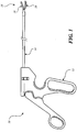
- FIG. 1 illustrates an embodiment of a surgical tool 10.
- surgical tool 10 is shown as a hand-held laparoscopic tool, which is configured to be inserted through a small incision in the abdomen of a patient.
- Surgical tool 10 in this embodiment includes a handle 12, a shaft 14, and an end portion 16.
- Shaft 14 is designed to connect handle 12 to end portion 16 and to communicate mechanical actions of handle 12 to end portion 16.
- Shaft 14 is further designed to communicate electrical signals from end portion 16 back to handle 12 as explained in more detail below.
- end portion 16 includes a tip 18 and a sensor array 20 formed on tip 18.
- tip 18 is a grasper.
- end portion 16 may include any suitable type of tip having any suitable functionality.
- sensor array 20 may be connected a portion of end portion 16 other than tip 18.
- shaft may be about 20 cm to 30 cm in length and tip 18 may be about 10 mm to 15 mm in length.
- a user can insert end portion 16 into the abdomen of the patient and control tip 18 of end portion 16.
- the surgeon can further manipulate handle 12 to control the location and orientation of tip 18 such that sensor array 20 is able to contact certain regions of the patient.
- Sensor array 20 can measure or test any desired property or parameter of the patient, such as, for example, pulse.
- tip 18 can be controlled to position sensor array 20 to accomplish certain contactless sensing.
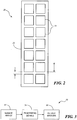
- FIG. 2 is a diagram illustrating an embodiment of sensor array 20 shown in FIG. 1 .
- Sensor array 20 includes a number of sensors 22 connected to a substrate 24, which is configured to hold sensors 22 in a pattern having a predetermined pitch between sensors 22. As shown in this diagram, sensor array 20 includes seven rows and two columns of sensors 22 from the perspective of handle 12 ( FIG. 1 ). It should be understood, however, that sensor array 20 can be arranged to include any number of rows and columns. In some embodiments, sensors 22 may be arranged in a pattern that does not particularly resemble a rectangular array. For example, sensors 22 can be positioned is a staggered pattern, circular pattern, etc.
- sensors 22 may include any suitable shape, e.g., rectangular, circular, elliptical, etc. According to the embodiment of FIG. 2 in which sensors 22 are square, sensors 22 may have widths and lengths of about 2 mm and may be separated by a distance of about 0.5 mm. In some embodiments, the size of sensors 22 may be smaller to allow a greater number of sensors to be positioned in sensor array 20. The size and number of sensors 22 may depend, for example, on the ability to miniaturize the particular type of sensor while keeping the integrity and usefulness of the sensor. If miniaturization techniques are used, the array of sensors 22 may include dozens of rows and columns of sensors 22. Sensors 22 may also be of any size and shape on substrate 24.
- Sensors 22 can be configured to sense any suitable property of the object under test.
- sensors 22 can be configured as pressure sensors using resistive or capacitive pressure sensing technologies.
- sensors 22 can include strain gauges, piezoelectric sensors, stiffness sensors, etc.
- strain gauges sensors 22 can provide additional information about contact force to finely tune a generally course measurement of force.
- piezoelectric sensors sensors 22 can generate ultrasound signals that reflect off portions of the object. In this case, echo signals can be detected by sensors 22 to determine the location of objects. The ultrasound emission and echo measurement technique may be particularly useful for sensing the location of luminal structures and for tumor tissue identification.
- Sensors 22 can also be configured as stiffness sensors that can detect nodules, e.g., tumors, or other stiff regions.
- the number of sensors 22 contacting the stiff region By processing the number of sensors 22 contacting the stiff region, a calculation can be made regarding the size of the nodules.
- the number of sensors 22 that sense relative stiffness can be used to determine the size of the nodule and thereby increase or decrease an output signal provided to the user to communicate the size.
- sensor array 20 can provide information indicative of the size of a particular feature, e.g., nodule, of the patient.
- Substrate 24 may include any suitable structure for supporting sensors 22 on tip 18 ( FIG. 1 ). Depending on the size, shape, and rigidity of tip 18, substrate 24 may be rigid or flexible to conform to tip 18. Also, substrate 24 may be planar or curved depending on the structure of tip 18. In the embodiment of FIG. 1 in which tip is a metal grasper with a curved bottom jaw, substrate 24 may be curved to conform to the curved shape of the bottom jaw. Also, since the jaw is substantially rigid, substrate 24 does not necessarily need to be rigid to provide needed support for sensors 22 and therefore can be flexible.
- FIG. 3 is a block diagram illustrating an embodiment of a system 30 for communicating spatial information about an object to a user.
- system 30 includes a sensor array 32, processing device 34, and output devices 36.
- system 30 contains sensor array 32, processing device 34, and output devices 36 on a hand-held tool or device.
- sensor array 32 may be positioned on a portion of a tool, e.g., a tool used for probing an object.
- Sensor array 32 is configured to include any type of sensing mechanisms to sense any suitable characteristic of the object.
- the sensed information from each sensor is communicated to processing device 34, which is configured to process the information according to specific algorithms.
- processing device 34 can determine various characteristics of the object. Processing device 34 may then communicate the processed information to output device 36, which is designed to present the information to the user in any suitable manner.
- Sensor array 32 may represent any suitable sensor array positioned on an end of a tool for detecting one or more specific properties of an object.
- sensor array 32 may be the same as or similar to sensor array 20 described with respect to FIGS. 1 and 2 .
- sensor array 32 includes a plurality of sensors, each capable of measuring properties of an object at predefined locations with respect to the other sensors.
- processing device 34 can determine or infer spatial information about the object. Processing device 34 may include different types of algorithms for extracting the particular information needed to calculate the spatial information.
- a surgeon may use a tool having sensor array 32 positioned on the tool for measuring pulse.
- processing device 34 may be configured to deduce that a blood vessel is positioned or oriented in that particular direction including that row of sensors where the pulse is detected.
- pulse information is detected along a column or across a diagonal, then the position or orientation of a blood vessel can be inferred accordingly.
- processing device 34 can also use any changes of the sensed information over time to extract temporal information.
- the signals can be detected in real time to allow the processing of time-related signals.
- processing device 34 may be able to detect peaks in the signals to determine when the signal is at its highest or lowest point.
- processing device 34 can detect phase differences, etc.
- processing device 34 is configured to use the spatial and temporal information to detect not only the orientation of blood vessels, but also the direction in which the blood flows through the vessels. For example, pulse information can be detected at one instance of time and detected again along the path of the vessel at a later instance.
- the sensors against which the blood vessel is in contact can sense the pulse.
- the sensors adjacent to those sensors that are in contact with the vessel can experience a loss of contact with tissue due to the lifting action of the pulsing vessel on the contacted sensors.
- the adjacent sensors may produce a signal that is 180 degrees out of phase with the pulse detecting sensors.
- Processing device 34 can be configured to detect this phenomenon to determine the location of blood vessels and for detecting pulse information.
- Processing device 34 may be a general-purpose or specific-purpose processor or microcontroller for processing the signals detected by sensor array 32.
- processing device 34 may include a plurality of processors for performing different functions with respect to system 30.
- processing device 34 may be associated with a memory device (not shown) for storing data and/or instructions.
- the memory may include one or more internally fixed storage units, removable storage units, and/or remotely accessible storage units, and the various storage units may include any combination of volatile memory and nonvolatile memory.
- Logical instructions, commands, and/or code can be implemented in software, firmware, or both, and stored in memory. In this respect, the logic code may be implemented as one or more computer programs that can be executed by processing device 34.
- logical instructions, commands, and/or code can be implemented in hardware and incorporated in processing device 34 using discrete logic circuitry, an application specific integrated circuit ("ASIC"), a programmable gate array (“PGA”), a field programmable gate array (“FPGA”), etc., or any combination thereof.
- ASIC application specific integrated circuit
- PGA programmable gate array
- FPGA field programmable gate array
- logical instructions, commands, and/or code can be implemented in both hardware in processing device 34 and software/firmware stored in the memory.
- Output devices 36 may include one or more mechanisms for communicating to a user information sensed by sensor array 32 and processed by processing device 34.
- Output devices 36 may include any suitable combination of display screens, speakers, tactile actuators, haptic effect devices, or other notification devices.
- output devices 36 may include any number of feedback mechanisms in any number of modes for providing any type of visual, audible, and/or tactile output to the user.
- output devices 36 may be used to provide feedback to the surgeon so that the surgeon can reposition the tool as necessary to align, orient, or position the tool to allow the sensing of a more reliable signal, to reduce pressure on particular organs, etc.
- output devices 36 can include haptic actuators, which is able to generate a vibration on handle 12.
- the haptic actuators can include one or more force applying mechanisms that are configured to apply a vibrotactile force to a user of surgical tool 10 or other device.
- the haptic actuators may include electromagnetic actuators, eccentric rotating mass (“ERM”) actuators in which an eccentric mass is moved by a motor, linear resonant actuator (“LRA”) in which a mass attached to a spring is driven back and forth, a "smart material” such as piezoelectric, electro-active polymers or shape memory alloys, or other suitable type of actuating device.
- FIG. 4 illustrates a system block diagram for a computer-assisted hand tool in which palpation algorithms can be deployed in an exemplary embodiment.
- the computer-assisted hand tool includes a plurality of sensors 40, which could include accelerometers for detecting and measuring the acceleration of a tool, and a pressure sensor array for detecting pulses during movement of the tip of the tool on the tissue being palpated.
- Processor 42 receives signals from sensors 40 and processes the received signals based on instructions stored in memory 44, which may include, among other things, palpation algorithms 46.
- processor 42 can cause an actuator 48 of the tool to play a haptic effect.
- haptic effect can refer to a tactile effect, tactile feedback, haptic feedback, force feedback, vibrotactile feedback, haptic cues, thermal feedback, kinesthetic feedback, etc.
- haptic effect can include the representation of any physical properties (e.g., stiffness, viscosity, etc.).
- the haptic effect played is characterized by one or more of the magnitude, frequency, and duration of the effect.
- the haptic effect can be dynamic based on a changing level of stiffness or deformation of the tissue being examined.
- processor 42 can be a laptop or personal computer that is electrically coupled to the tool.
- the laptop or personal computer can have a graphical user interface (GUI) 50 that enables the user to select optional processing steps for the palpation algorithms.
- GUI graphical user interface
- Memory 44 can be any type of storage device or computer readable medium capable of storing the instructions for palpation algorithms 46. Memory 44 can include random access memory, read-only memory, etc.
- processor 42 can be an application specific integrated circuit (ASIC) that is a component of the tool.
- the instructions for palpation algorithms 46 can be embedded in processor 42.
- sensor array 40 can include a 2X7 array of pressure transducers. Each pressure transducer can be in contact with the tissue being palpated, therefore, each transducer is processed for pulses received. Each transducer can detect zero or more pulses in a predetermined time window.
- Actuator 48 can generate a vibration on the handle of the tool. More specifically, the actuator 48 can include a force applying mechanism that applies a vibrotactile force to the tool based on a level of stiffness or deformation of the tissue being examined.
- One parameter of the actuator that can be used in some embodiments is the peak voltage applied during the playing of haptic effects.
- FIG. 5 is a flow diagram of an example of a method of operating a tool having a sensor array, which does not form part of the invention.
- a user is allowed to manipulate a tool according to a normal use of the tool.
- the user may manipulate a handle, buttons, or other feature on the tool to control a functional portion of the tool.
- the controlled portion may be a portion that is positioned on an opposite end from the handle. The controlled portion can be probed around to contact an object being tested or to be placed in proximity to the object being tested, depending on the particular type of parameter being measured.
- a parameter of the object is sensed at multiple locations.
- the multiple locations may represent the positioning of a number of sensors mounted on or relative to the tool, such as sensors that may be positioned on or near the controlled portion of the tool.
- the sensing locations may form a predefined pattern, such as a rectangular array having rows and columns. In other embodiments, the sensing locations may include any other suitable pattern.
- the sensed properties are processed to obtain spatial information about the object being tested. Based on the properties sensed at the multiple locations and based on a predetermined knowledge of the location and orientation of the sensors, spatial information can be obtained.
- the sensed properties may be related to the blood of the patient. For example, if pulse information is detected at some sensor locations, the sensed information can be processed to determine the location and orientation of blood vessels of the patient.
- the spatial information can also be obtained by processing the information at regular time intervals, allowing both spatial and temporal information to be obtained.
- the spatiotemporal information can be used to determine not only the location and orientation of the blood vessels, but also the direction in which the blood flows through the blood vessels.
- a signal may be strong at one sensor location at one time and, after a short delay, the signal may be strong at another sensor location, thereby indicating the flow direction.
- the processing associated with block 46 is able to decode the sensed information from the multiple locations at multiple times to compute the spatial and/or spatiotemporal information.
- an output is provided to the user to indicate the spatial information.
- this information can also be output to the user.
- the output may be presented in any suitable form.
- the output may be a haptic or tactile effect imposed on the user.
- the output may be haptic, audible, and/or visual. Any suitable combination of output mechanisms or actuators can be used to present the output.
- haptic actuators can be arranged in an array or other pattern resembling the array or pattern of the sensors. In this case, the sensed signals can be mapped to provide a haptic effect to represent the spatial information sensed by the sensors.
- routines, steps, processes, or operations described herein may represent any module or code sequence that can be implemented in software or firmware.
- these modules and code sequences can include commands or instructions for executing the specific logical routines, steps, processes, or operations within physical components.
- two or more of the routines, steps, processes, and/or operations described herein may be executed substantially simultaneously or in a different order than explicitly described, as would be understood by one of ordinary skill in the art.
Landscapes
- Health & Medical Sciences (AREA)
- Life Sciences & Earth Sciences (AREA)
- Surgery (AREA)
- Engineering & Computer Science (AREA)
- Animal Behavior & Ethology (AREA)
- Veterinary Medicine (AREA)
- Public Health (AREA)
- Biomedical Technology (AREA)
- Heart & Thoracic Surgery (AREA)
- Medical Informatics (AREA)
- Molecular Biology (AREA)
- General Health & Medical Sciences (AREA)
- Nuclear Medicine, Radiotherapy & Molecular Imaging (AREA)
- Physics & Mathematics (AREA)
- Biophysics (AREA)
- Pathology (AREA)
- Radiology & Medical Imaging (AREA)
- Gynecology & Obstetrics (AREA)
- Vascular Medicine (AREA)
- Ophthalmology & Optometry (AREA)
- Robotics (AREA)
- Dentistry (AREA)
- Oral & Maxillofacial Surgery (AREA)
- Surgical Instruments (AREA)
- Measuring Pulse, Heart Rate, Blood Pressure Or Blood Flow (AREA)
- Endoscopes (AREA)
- Ultra Sonic Daignosis Equipment (AREA)
Applications Claiming Priority (2)
| Application Number | Priority Date | Filing Date | Title |
|---|---|---|---|
| US12/333,600 US8551002B2 (en) | 2008-12-12 | 2008-12-12 | Spatial array of sensors mounted on a tool |
| PCT/US2009/066908 WO2010068572A1 (en) | 2008-12-12 | 2009-12-07 | Spatial array of sensors mounted on a tool |
Publications (2)
| Publication Number | Publication Date |
|---|---|
| EP2355709A1 EP2355709A1 (en) | 2011-08-17 |
| EP2355709B1 true EP2355709B1 (en) | 2018-10-10 |
Family
ID=41697943
Family Applications (1)
| Application Number | Title | Priority Date | Filing Date |
|---|---|---|---|
| EP09765212.7A Not-in-force EP2355709B1 (en) | 2008-12-12 | 2009-12-07 | Spatial array of sensors mounted on a tool |
Country Status (4)
| Country | Link |
|---|---|
| US (1) | US8551002B2 (enExample) |
| EP (1) | EP2355709B1 (enExample) |
| JP (1) | JP5683482B2 (enExample) |
| WO (1) | WO2010068572A1 (enExample) |
Families Citing this family (20)
| Publication number | Priority date | Publication date | Assignee | Title |
|---|---|---|---|---|
| US8337426B2 (en) * | 2009-03-24 | 2012-12-25 | Biomet Manufacturing Corp. | Method and apparatus for aligning and securing an implant relative to a patient |
| US8303622B2 (en) * | 2007-03-14 | 2012-11-06 | St. Jude Medical, Inc. | Heart valve chordae replacement methods and apparatus |
| US8709036B2 (en) * | 2009-05-13 | 2014-04-29 | University of Pittsburgh—of the Commonwealth System of Higher Education | Tension transducing forceps |
| EP2513941B1 (en) * | 2009-12-16 | 2016-05-25 | Husqvarna AB | Electric hand tool with activation indication device |
| CN102711635B (zh) * | 2010-01-15 | 2015-06-10 | 意美森公司 | 用于带有触觉反馈的微创外科手术工具的系统和方法 |
| CN101912290B (zh) * | 2010-07-22 | 2012-09-19 | 徐生源 | 多功能腹腔镜手术可弯形手术钳 |
| US8801710B2 (en) | 2010-12-07 | 2014-08-12 | Immersion Corporation | Electrosurgical sealing tool having haptic feedback |
| US8523043B2 (en) | 2010-12-07 | 2013-09-03 | Immersion Corporation | Surgical stapler having haptic feedback |
| KR20140008728A (ko) * | 2012-07-11 | 2014-01-22 | 삼성전자주식회사 | 로봇을 이용한 촉진 장치 및 방법 |
| US9443401B2 (en) | 2013-09-06 | 2016-09-13 | Immersion Corporation | Automatic remote sensing and haptic conversion system |
| CN106163409B (zh) | 2014-03-31 | 2022-09-02 | 皇家飞利浦有限公司 | 用于超声图像采集的触觉反馈 |
| US10369045B2 (en) * | 2014-07-29 | 2019-08-06 | The Johns Hopkins University | Micromanipulation systems and methods |
| US10613629B2 (en) | 2015-03-27 | 2020-04-07 | Chad Laurendeau | System and method for force feedback interface devices |
| US20170042626A1 (en) * | 2015-07-31 | 2017-02-16 | Advanced Tactile Imaging, Inc. | Method and probe for providing tactile feedback in laparoscopic surgery |
| JP6885341B2 (ja) | 2015-11-30 | 2021-06-16 | ソニーグループ株式会社 | 内視鏡下手術用手持ち器具 |
| WO2018112216A1 (en) * | 2016-12-15 | 2018-06-21 | Intuitive Surgical Operations, Inc. | Detection of user touch on controller handle |
| NL2022018B1 (en) * | 2018-11-16 | 2020-05-26 | Efi Holding B V | Surgical instrument |
| US20210228262A1 (en) | 2020-01-29 | 2021-07-29 | Covidien Lp | System and methods for identifying vessels within tissue |
| US12426941B2 (en) | 2020-03-20 | 2025-09-30 | Covidien Lp | Surgical instruments and systems configured to detect, analyze, and/or distinguish smoke and steam during a surgical procedure |
| US12426890B2 (en) * | 2021-03-19 | 2025-09-30 | Evalve, Inc. | Systems for tissue grasping and assessment |
Family Cites Families (18)
| Publication number | Priority date | Publication date | Assignee | Title |
|---|---|---|---|---|
| US5451924A (en) | 1993-01-14 | 1995-09-19 | Massachusetts Institute Of Technology | Apparatus for providing sensory substitution of force feedback |
| DE4332580A1 (de) | 1993-09-24 | 1995-03-30 | Deutsche Aerospace | Vorrichtung zur Nachbildung oder Simulation des Tastsinns in einem chirurgischen Instrument |
| DE19527957C1 (de) * | 1995-07-29 | 1996-08-22 | Karlsruhe Forschzent | Taktiler, optoelektronischer Drucksensor |
| JP3318158B2 (ja) * | 1995-08-08 | 2002-08-26 | テルモ株式会社 | 体内挿入具 |
| US5833634A (en) | 1995-11-09 | 1998-11-10 | Uromed Corporation | Tissue examination |
| US5989199A (en) | 1996-11-27 | 1999-11-23 | Assurance Medical, Inc. | Tissue examination |
| US5967990A (en) * | 1998-08-13 | 1999-10-19 | President And Fellows Of Harvard College | Surgical probe comprising visible markings on an elastic membrane |
| JP2000116786A (ja) * | 1998-10-12 | 2000-04-25 | Terumo Corp | 電気伝導路を有する体内挿入具の製造方法 |
| US6500119B1 (en) | 1999-12-01 | 2002-12-31 | Medical Tactile, Inc. | Obtaining images of structures in bodily tissue |
| US6494882B1 (en) * | 2000-07-25 | 2002-12-17 | Verimetra, Inc. | Cutting instrument having integrated sensors |
| US6569108B2 (en) | 2001-03-28 | 2003-05-27 | Profile, Llc | Real time mechanical imaging of the prostate |
| US20080287813A1 (en) | 2004-03-30 | 2008-11-20 | Eidgenossische Technische Hochschule Zurich | Blood Pressure Monitoring Device and Methods for Making and for Using Such a Device |
| US7875036B2 (en) * | 2004-10-27 | 2011-01-25 | Vascular Control Systems, Inc. | Short term treatment for uterine disorder |
| US20070049973A1 (en) | 2005-08-29 | 2007-03-01 | Vascular Control Systems, Inc. | Method and device for treating adenomyosis and endometriosis |
| US20070197895A1 (en) * | 2006-02-17 | 2007-08-23 | Sdgi Holdings, Inc. | Surgical instrument to assess tissue characteristics |
| US20080243146A1 (en) | 2007-01-04 | 2008-10-02 | Todd Sloan | Locating and occluding vessels |
| CA2679523C (en) * | 2007-03-26 | 2015-06-23 | Tyco Healthcare Group Lp | Endoscopic surgical clip applier |
| US20090234273A1 (en) * | 2008-03-17 | 2009-09-17 | Alfred Intoccia | Surgical trocar with feedback |
-
2008
- 2008-12-12 US US12/333,600 patent/US8551002B2/en not_active Expired - Fee Related
-
2009
- 2009-12-07 JP JP2011540791A patent/JP5683482B2/ja not_active Expired - Fee Related
- 2009-12-07 EP EP09765212.7A patent/EP2355709B1/en not_active Not-in-force
- 2009-12-07 WO PCT/US2009/066908 patent/WO2010068572A1/en not_active Ceased
Non-Patent Citations (1)
| Title |
|---|
| None * |
Also Published As
| Publication number | Publication date |
|---|---|
| JP2012511400A (ja) | 2012-05-24 |
| JP5683482B2 (ja) | 2015-03-11 |
| US8551002B2 (en) | 2013-10-08 |
| WO2010068572A1 (en) | 2010-06-17 |
| EP2355709A1 (en) | 2011-08-17 |
| US20100152586A1 (en) | 2010-06-17 |
Similar Documents
| Publication | Publication Date | Title |
|---|---|---|
| EP2355709B1 (en) | Spatial array of sensors mounted on a tool | |
| JP5921195B2 (ja) | 器具のハンドルへの触覚フィードバックの提供 | |
| EP2296555B1 (en) | Tool having multiple feedback devices | |
| EP2381861B1 (en) | Palpation algorithms for computer-augmented hand tools | |
| DK2401980T3 (en) | Pressure sensing a multi-arm catheter | |
| ES2467415T3 (es) | Catéter con detección de presión | |
| US20130321262A1 (en) | Operating system with haptic interface for minimally invasive, hand-held surgical instrument | |
| US8596111B2 (en) | System for sensing and displaying softness and force | |
| CN101730506A (zh) | 带有触觉反馈的微创外科工具 | |
| US10639117B2 (en) | Tactile feedback system for robotic surgery | |
| EP3430990A1 (en) | Pulse wave detection device and biological information measurement device | |
| EP3443895B1 (en) | Pulse wave detection device, control method for pulse wave detection device, and control program for pulse wave detection device | |
| JP6586955B2 (ja) | 接触検出器具 | |
| US11278210B2 (en) | Pulse wave detection device, and vital information measurement device | |
| JP2009011628A (ja) | 画像診断支援装置 |
Legal Events
| Date | Code | Title | Description |
|---|---|---|---|
| PUAI | Public reference made under article 153(3) epc to a published international application that has entered the european phase |
Free format text: ORIGINAL CODE: 0009012 |
|
| 17P | Request for examination filed |
Effective date: 20101116 |
|
| AK | Designated contracting states |
Kind code of ref document: A1 Designated state(s): AT BE BG CH CY CZ DE DK EE ES FI FR GB GR HR HU IE IS IT LI LT LU LV MC MK MT NL NO PL PT RO SE SI SK SM TR |
|
| DAX | Request for extension of the european patent (deleted) | ||
| RAP1 | Party data changed (applicant data changed or rights of an application transferred) |
Owner name: IMMERSION CORPORATION |
|
| 17Q | First examination report despatched |
Effective date: 20150515 |
|
| RAP1 | Party data changed (applicant data changed or rights of an application transferred) |
Owner name: IMMERSION CORPORATION |
|
| REG | Reference to a national code |
Ref country code: DE Ref legal event code: R079 Ref document number: 602009055001 Country of ref document: DE Free format text: PREVIOUS MAIN CLASS: A61B0017000000 Ipc: A61B0017290000 |
|
| RIC1 | Information provided on ipc code assigned before grant |
Ipc: A61B 17/29 20060101AFI20180306BHEP Ipc: A61B 5/00 20060101ALN20180306BHEP Ipc: A61B 17/00 20060101ALN20180306BHEP Ipc: A61B 8/08 20060101ALN20180306BHEP Ipc: A61B 90/00 20160101ALN20180306BHEP Ipc: A61B 5/0215 20060101ALI20180306BHEP Ipc: A61B 17/34 20060101ALN20180306BHEP |
|
| GRAP | Despatch of communication of intention to grant a patent |
Free format text: ORIGINAL CODE: EPIDOSNIGR1 |
|
| STAA | Information on the status of an ep patent application or granted ep patent |
Free format text: STATUS: GRANT OF PATENT IS INTENDED |
|
| INTG | Intention to grant announced |
Effective date: 20180416 |
|
| GRAS | Grant fee paid |
Free format text: ORIGINAL CODE: EPIDOSNIGR3 |
|
| GRAA | (expected) grant |
Free format text: ORIGINAL CODE: 0009210 |
|
| STAA | Information on the status of an ep patent application or granted ep patent |
Free format text: STATUS: THE PATENT HAS BEEN GRANTED |
|
| AK | Designated contracting states |
Kind code of ref document: B1 Designated state(s): AT BE BG CH CY CZ DE DK EE ES FI FR GB GR HR HU IE IS IT LI LT LU LV MC MK MT NL NO PL PT RO SE SI SK SM TR |
|
| REG | Reference to a national code |
Ref country code: GB Ref legal event code: FG4D |
|
| REG | Reference to a national code |
Ref country code: CH Ref legal event code: EP Ref country code: AT Ref legal event code: REF Ref document number: 1050330 Country of ref document: AT Kind code of ref document: T Effective date: 20181015 |
|
| REG | Reference to a national code |
Ref country code: IE Ref legal event code: FG4D |
|
| REG | Reference to a national code |
Ref country code: DE Ref legal event code: R096 Ref document number: 602009055001 Country of ref document: DE |
|
| REG | Reference to a national code |
Ref country code: NL Ref legal event code: MP Effective date: 20181010 |
|
| REG | Reference to a national code |
Ref country code: LT Ref legal event code: MG4D |
|
| PGFP | Annual fee paid to national office [announced via postgrant information from national office to epo] |
Ref country code: GB Payment date: 20181227 Year of fee payment: 10 Ref country code: FR Payment date: 20181226 Year of fee payment: 10 |
|
| REG | Reference to a national code |
Ref country code: AT Ref legal event code: MK05 Ref document number: 1050330 Country of ref document: AT Kind code of ref document: T Effective date: 20181010 |
|
| PG25 | Lapsed in a contracting state [announced via postgrant information from national office to epo] |
Ref country code: NL Free format text: LAPSE BECAUSE OF FAILURE TO SUBMIT A TRANSLATION OF THE DESCRIPTION OR TO PAY THE FEE WITHIN THE PRESCRIBED TIME-LIMIT Effective date: 20181010 |
|
| PG25 | Lapsed in a contracting state [announced via postgrant information from national office to epo] |
Ref country code: LV Free format text: LAPSE BECAUSE OF FAILURE TO SUBMIT A TRANSLATION OF THE DESCRIPTION OR TO PAY THE FEE WITHIN THE PRESCRIBED TIME-LIMIT Effective date: 20181010 Ref country code: AT Free format text: LAPSE BECAUSE OF FAILURE TO SUBMIT A TRANSLATION OF THE DESCRIPTION OR TO PAY THE FEE WITHIN THE PRESCRIBED TIME-LIMIT Effective date: 20181010 Ref country code: ES Free format text: LAPSE BECAUSE OF FAILURE TO SUBMIT A TRANSLATION OF THE DESCRIPTION OR TO PAY THE FEE WITHIN THE PRESCRIBED TIME-LIMIT Effective date: 20181010 Ref country code: BG Free format text: LAPSE BECAUSE OF FAILURE TO SUBMIT A TRANSLATION OF THE DESCRIPTION OR TO PAY THE FEE WITHIN THE PRESCRIBED TIME-LIMIT Effective date: 20190110 Ref country code: PL Free format text: LAPSE BECAUSE OF FAILURE TO SUBMIT A TRANSLATION OF THE DESCRIPTION OR TO PAY THE FEE WITHIN THE PRESCRIBED TIME-LIMIT Effective date: 20181010 Ref country code: HR Free format text: LAPSE BECAUSE OF FAILURE TO SUBMIT A TRANSLATION OF THE DESCRIPTION OR TO PAY THE FEE WITHIN THE PRESCRIBED TIME-LIMIT Effective date: 20181010 Ref country code: FI Free format text: LAPSE BECAUSE OF FAILURE TO SUBMIT A TRANSLATION OF THE DESCRIPTION OR TO PAY THE FEE WITHIN THE PRESCRIBED TIME-LIMIT Effective date: 20181010 Ref country code: LT Free format text: LAPSE BECAUSE OF FAILURE TO SUBMIT A TRANSLATION OF THE DESCRIPTION OR TO PAY THE FEE WITHIN THE PRESCRIBED TIME-LIMIT Effective date: 20181010 Ref country code: IS Free format text: LAPSE BECAUSE OF FAILURE TO SUBMIT A TRANSLATION OF THE DESCRIPTION OR TO PAY THE FEE WITHIN THE PRESCRIBED TIME-LIMIT Effective date: 20190210 Ref country code: NO Free format text: LAPSE BECAUSE OF FAILURE TO SUBMIT A TRANSLATION OF THE DESCRIPTION OR TO PAY THE FEE WITHIN THE PRESCRIBED TIME-LIMIT Effective date: 20190110 |
|
| PGFP | Annual fee paid to national office [announced via postgrant information from national office to epo] |
Ref country code: DE Payment date: 20181231 Year of fee payment: 10 |
|
| PG25 | Lapsed in a contracting state [announced via postgrant information from national office to epo] |
Ref country code: GR Free format text: LAPSE BECAUSE OF FAILURE TO SUBMIT A TRANSLATION OF THE DESCRIPTION OR TO PAY THE FEE WITHIN THE PRESCRIBED TIME-LIMIT Effective date: 20190111 Ref country code: PT Free format text: LAPSE BECAUSE OF FAILURE TO SUBMIT A TRANSLATION OF THE DESCRIPTION OR TO PAY THE FEE WITHIN THE PRESCRIBED TIME-LIMIT Effective date: 20190210 Ref country code: SE Free format text: LAPSE BECAUSE OF FAILURE TO SUBMIT A TRANSLATION OF THE DESCRIPTION OR TO PAY THE FEE WITHIN THE PRESCRIBED TIME-LIMIT Effective date: 20181010 |
|
| REG | Reference to a national code |
Ref country code: DE Ref legal event code: R097 Ref document number: 602009055001 Country of ref document: DE |
|
| PG25 | Lapsed in a contracting state [announced via postgrant information from national office to epo] |
Ref country code: DK Free format text: LAPSE BECAUSE OF FAILURE TO SUBMIT A TRANSLATION OF THE DESCRIPTION OR TO PAY THE FEE WITHIN THE PRESCRIBED TIME-LIMIT Effective date: 20181010 Ref country code: IT Free format text: LAPSE BECAUSE OF FAILURE TO SUBMIT A TRANSLATION OF THE DESCRIPTION OR TO PAY THE FEE WITHIN THE PRESCRIBED TIME-LIMIT Effective date: 20181010 Ref country code: CZ Free format text: LAPSE BECAUSE OF FAILURE TO SUBMIT A TRANSLATION OF THE DESCRIPTION OR TO PAY THE FEE WITHIN THE PRESCRIBED TIME-LIMIT Effective date: 20181010 |
|
| REG | Reference to a national code |
Ref country code: CH Ref legal event code: PL |
|
| PLBE | No opposition filed within time limit |
Free format text: ORIGINAL CODE: 0009261 |
|
| STAA | Information on the status of an ep patent application or granted ep patent |
Free format text: STATUS: NO OPPOSITION FILED WITHIN TIME LIMIT |
|
| PG25 | Lapsed in a contracting state [announced via postgrant information from national office to epo] |
Ref country code: LU Free format text: LAPSE BECAUSE OF NON-PAYMENT OF DUE FEES Effective date: 20181207 Ref country code: MC Free format text: LAPSE BECAUSE OF FAILURE TO SUBMIT A TRANSLATION OF THE DESCRIPTION OR TO PAY THE FEE WITHIN THE PRESCRIBED TIME-LIMIT Effective date: 20181010 Ref country code: SK Free format text: LAPSE BECAUSE OF FAILURE TO SUBMIT A TRANSLATION OF THE DESCRIPTION OR TO PAY THE FEE WITHIN THE PRESCRIBED TIME-LIMIT Effective date: 20181010 Ref country code: EE Free format text: LAPSE BECAUSE OF FAILURE TO SUBMIT A TRANSLATION OF THE DESCRIPTION OR TO PAY THE FEE WITHIN THE PRESCRIBED TIME-LIMIT Effective date: 20181010 Ref country code: SM Free format text: LAPSE BECAUSE OF FAILURE TO SUBMIT A TRANSLATION OF THE DESCRIPTION OR TO PAY THE FEE WITHIN THE PRESCRIBED TIME-LIMIT Effective date: 20181010 Ref country code: RO Free format text: LAPSE BECAUSE OF FAILURE TO SUBMIT A TRANSLATION OF THE DESCRIPTION OR TO PAY THE FEE WITHIN THE PRESCRIBED TIME-LIMIT Effective date: 20181010 |
|
| 26N | No opposition filed |
Effective date: 20190711 |
|
| REG | Reference to a national code |
Ref country code: IE Ref legal event code: MM4A |
|
| REG | Reference to a national code |
Ref country code: BE Ref legal event code: MM Effective date: 20181231 |
|
| PG25 | Lapsed in a contracting state [announced via postgrant information from national office to epo] |
Ref country code: IE Free format text: LAPSE BECAUSE OF NON-PAYMENT OF DUE FEES Effective date: 20181207 Ref country code: SI Free format text: LAPSE BECAUSE OF FAILURE TO SUBMIT A TRANSLATION OF THE DESCRIPTION OR TO PAY THE FEE WITHIN THE PRESCRIBED TIME-LIMIT Effective date: 20181010 |
|
| PG25 | Lapsed in a contracting state [announced via postgrant information from national office to epo] |
Ref country code: BE Free format text: LAPSE BECAUSE OF NON-PAYMENT OF DUE FEES Effective date: 20181231 |
|
| PG25 | Lapsed in a contracting state [announced via postgrant information from national office to epo] |
Ref country code: LI Free format text: LAPSE BECAUSE OF NON-PAYMENT OF DUE FEES Effective date: 20181231 Ref country code: CH Free format text: LAPSE BECAUSE OF NON-PAYMENT OF DUE FEES Effective date: 20181231 |
|
| PG25 | Lapsed in a contracting state [announced via postgrant information from national office to epo] |
Ref country code: MT Free format text: LAPSE BECAUSE OF NON-PAYMENT OF DUE FEES Effective date: 20181207 |
|
| PG25 | Lapsed in a contracting state [announced via postgrant information from national office to epo] |
Ref country code: TR Free format text: LAPSE BECAUSE OF FAILURE TO SUBMIT A TRANSLATION OF THE DESCRIPTION OR TO PAY THE FEE WITHIN THE PRESCRIBED TIME-LIMIT Effective date: 20181010 |
|
| PG25 | Lapsed in a contracting state [announced via postgrant information from national office to epo] |
Ref country code: MK Free format text: LAPSE BECAUSE OF NON-PAYMENT OF DUE FEES Effective date: 20181010 Ref country code: CY Free format text: LAPSE BECAUSE OF FAILURE TO SUBMIT A TRANSLATION OF THE DESCRIPTION OR TO PAY THE FEE WITHIN THE PRESCRIBED TIME-LIMIT Effective date: 20181010 Ref country code: HU Free format text: LAPSE BECAUSE OF FAILURE TO SUBMIT A TRANSLATION OF THE DESCRIPTION OR TO PAY THE FEE WITHIN THE PRESCRIBED TIME-LIMIT; INVALID AB INITIO Effective date: 20091207 |
|
| REG | Reference to a national code |
Ref country code: DE Ref legal event code: R119 Ref document number: 602009055001 Country of ref document: DE |
|
| GBPC | Gb: european patent ceased through non-payment of renewal fee |
Effective date: 20191207 |
|
| PG25 | Lapsed in a contracting state [announced via postgrant information from national office to epo] |
Ref country code: FR Free format text: LAPSE BECAUSE OF NON-PAYMENT OF DUE FEES Effective date: 20191231 Ref country code: DE Free format text: LAPSE BECAUSE OF NON-PAYMENT OF DUE FEES Effective date: 20200701 Ref country code: GB Free format text: LAPSE BECAUSE OF NON-PAYMENT OF DUE FEES Effective date: 20191207 |