EP2354397B1 - Mécanisme de verrouillage d un objet mobile - Google Patents
Mécanisme de verrouillage d un objet mobile Download PDFInfo
- Publication number
- EP2354397B1 EP2354397B1 EP09827533.2A EP09827533A EP2354397B1 EP 2354397 B1 EP2354397 B1 EP 2354397B1 EP 09827533 A EP09827533 A EP 09827533A EP 2354397 B1 EP2354397 B1 EP 2354397B1
- Authority
- EP
- European Patent Office
- Prior art keywords
- mobile member
- lock
- knob
- housing
- rotational axis
- Prior art date
- Legal status (The legal status is an assumption and is not a legal conclusion. Google has not performed a legal analysis and makes no representation as to the accuracy of the status listed.)
- Not-in-force
Links
Images


Classifications
-
- B—PERFORMING OPERATIONS; TRANSPORTING
- B60—VEHICLES IN GENERAL
- B60R—VEHICLES, VEHICLE FITTINGS, OR VEHICLE PARTS, NOT OTHERWISE PROVIDED FOR
- B60R7/00—Stowing or holding appliances inside vehicle primarily intended for personal property smaller than suit-cases, e.g. travelling articles, or maps
- B60R7/04—Stowing or holding appliances inside vehicle primarily intended for personal property smaller than suit-cases, e.g. travelling articles, or maps in driver or passenger space, e.g. using racks
- B60R7/06—Stowing or holding appliances inside vehicle primarily intended for personal property smaller than suit-cases, e.g. travelling articles, or maps in driver or passenger space, e.g. using racks mounted on or below dashboards
-
- E—FIXED CONSTRUCTIONS
- E05—LOCKS; KEYS; WINDOW OR DOOR FITTINGS; SAFES
- E05B—LOCKS; ACCESSORIES THEREFOR; HANDCUFFS
- E05B77/00—Vehicle locks characterised by special functions or purposes
- E05B77/02—Vehicle locks characterised by special functions or purposes for accident situations
- E05B77/04—Preventing unwanted lock actuation, e.g. unlatching, at the moment of collision
- E05B77/06—Preventing unwanted lock actuation, e.g. unlatching, at the moment of collision by means of inertial forces
-
- E—FIXED CONSTRUCTIONS
- E05—LOCKS; KEYS; WINDOW OR DOOR FITTINGS; SAFES
- E05B—LOCKS; ACCESSORIES THEREFOR; HANDCUFFS
- E05B83/00—Vehicle locks specially adapted for particular types of wing or vehicle
- E05B83/28—Locks for glove compartments, console boxes, fuel inlet covers or the like
- E05B83/30—Locks for glove compartments, console boxes, fuel inlet covers or the like for glove compartments
-
- E—FIXED CONSTRUCTIONS
- E05—LOCKS; KEYS; WINDOW OR DOOR FITTINGS; SAFES
- E05B—LOCKS; ACCESSORIES THEREFOR; HANDCUFFS
- E05B83/00—Vehicle locks specially adapted for particular types of wing or vehicle
- E05B83/28—Locks for glove compartments, console boxes, fuel inlet covers or the like
- E05B83/32—Locks for glove compartments, console boxes, fuel inlet covers or the like for console boxes, e.g. between passenger seats
-
- E—FIXED CONSTRUCTIONS
- E05—LOCKS; KEYS; WINDOW OR DOOR FITTINGS; SAFES
- E05B—LOCKS; ACCESSORIES THEREFOR; HANDCUFFS
- E05B85/00—Details of vehicle locks not provided for in groups E05B77/00 - E05B83/00
- E05B85/10—Handles
- E05B85/14—Handles pivoted about an axis parallel to the wing
-
- Y—GENERAL TAGGING OF NEW TECHNOLOGICAL DEVELOPMENTS; GENERAL TAGGING OF CROSS-SECTIONAL TECHNOLOGIES SPANNING OVER SEVERAL SECTIONS OF THE IPC; TECHNICAL SUBJECTS COVERED BY FORMER USPC CROSS-REFERENCE ART COLLECTIONS [XRACs] AND DIGESTS
- Y10—TECHNICAL SUBJECTS COVERED BY FORMER USPC
- Y10T—TECHNICAL SUBJECTS COVERED BY FORMER US CLASSIFICATION
- Y10T292/00—Closure fasteners
- Y10T292/08—Bolts
- Y10T292/0911—Hooked end
- Y10T292/0926—Spring projected
- Y10T292/0928—Operating means
- Y10T292/0934—Rigid
Definitions
- the present invention relates to a lock mechanism of a mobile member, for example, in a case of being attached to an inside of a vehicle interior, at a time of a sudden stop or a crash of a vehicle, the lock mechanism of the mobile member can prevent the mobile member from abruptly moving and protruding beforehand.
- a protruded portion protruding from the knob is fitted in a concave groove of a lock main body, and blocks a rotation of the knob (see paragraph number [0017] and Fig. 4 of the Patent Document 1).
- the present invention is made in view of the problem of the above-mentioned conventional technology, and an object of the present invention is as follows.
- the present invention is made so as not to be able to release the locked state by an action of the inertial force and the like, and to prevent the mobile member from abruptly moving beforehand.
- the lock mechanism of the mobile member can prevent the mobile member from abruptly moving and protruding beforehand.
- the present invention has the following features.
- a lock mechanism for example, a small object storage device for a vehicle
- a lock mechanism comprises the following structure.
- the small object storage device for the vehicle is exemplified, this is not limited to the above, and may be a table, cup holder, ashtray, or the like. Also, an attachment position is not limited to a car, and may be other vehicles, furniture, office equipment, or the like.
- Base for example, a housing
- the housing is exemplified, this is not limited to the above.
- a mobile member is movably supported relative to the base (for example, the housing).
- the lock device is disposed between the base (for example, the housing) and the mobile member, and locks the mobile member.
- the lock device comprises the following structure.
- a lock portion is provided in either one (for example, the housing) of the base (for example, the housing) or the mobile member, and locks in a state wherein the mobile member is housed in the base (for example, the housing).
- a knob is rotatably supported to the other (for example, the mobile member) of the base (for example, the housing) or the mobile member, and includes a locking portion, which is hooked in the lock portion, on one end portion by sandwiching a rotational axis thereof, and an operating portion capable of releasing a locked state of the locking portion, which has been locked by being hooked in the lock portion by rotating, on the other end portion.
- the lock portion is provided in the base (for example, the housing), and the knob is rotatably supported to the mobile member, they are not limited to the above, and although this is not shown in the figures, contrarily, the knob may be rotatably supported to the base (for example, the housing), and the lock portion may be provided in the mobile member.
- a return spring is for urging the locking portion toward a direction of being hooked in the lock portion.
- the lock device comprises the following structure.
- An elongate hole is for movably supporting at least one end portion of the rotational axis along a moving direction (for example, a sliding direction) of the mobile member.
- Urging means for example, the return spring also serving as the urging means
- the urging means (for example, the return spring also serving as the urging means) is for urging one end portion of the rotational axis toward a position of an immediate front side of the elongate hole.
- a rotation blocking portion is for blocking a rotation of the knob when one end portion of the rotational axis moves toward a deep side of the elongate hole against an urging force of the urging means (for example, the return spring also serving as the urging means).
- the return spring may also serve as the urging means (for example, the return spring also serving as the urging means).
- the rotation blocking portion may abut against the locking portion.
- the knob can be prevented from damage.
- the lock mechanism according to the present invention may be structured as follows.
- the mobile member is disposed so as to protrude toward a front from a back of the vehicle (not shown in the figures).
- the mobile member can be prevented from abruptly protruding toward the front from the back of the vehicle.
- the present invention can prevent the mobile member from abruptly moving and protruding beforehand.
- Figs. 1 to 9 respectively show one example of an embodiment of the present invention.
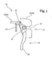
- Fig. 1 is a side view of a lock device in a state wherein a rotation of a knob is blocked;
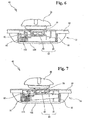
- Fig. 2 is a side view of a small object storage device for a vehicle in a state wherein a mobile member is protruded;
- Fig. 3 is a plan view of the small object storage device for the vehicle in the state wherein the mobile member is protruded;
- Fig. 4 corresponds to Fig. 2 , and is a side view of a state wherein the mobile member is housed;
- Fig. 5 corresponds to Fig. 3 , and is a plan view of the state wherein the mobile member is housed;
- Fig. 6 is a plan view of the lock device;
- Fig. 7 corresponds to Fig.
- Fig. 6 corresponds to Fig. 1 , and is a side view showing a locked state
- Fig. 9 corresponds to Fig. 1 , and is a side view showing an unlocked state, respectively.
- the reference numeral 10 represents a small object storage device for a vehicle, and although it is not shown in the drawings, the small object storage device for the vehicle is disposed in an inside of a vehicle interior.
- the above-mentioned small object storage device 10 for the vehicle is one example of a lock mechanism of a mobile member 30.
- the lock mechanism is not limited to the small object storage device 10 for the vehicle, and may be a table, cup holder, ashtray, or the like.
- an attachment position of the lock mechanism is not limited to a car, and may be other vehicles, furniture, office equipment, or the like.
- the small object storage device 10 for the vehicle roughly comprises the following portions.
- the portions of the small object storage device 10 for the vehicle are not limited to the above-mentioned (1) to (3).
- the housing 20 includes an opening portion 21 at least in a front face.
- the above-mentioned housing 20 is one example of a base.
- the base is not limited to the housing 20.
- the housing 20 is made from metal, and formed in a box shape whose front and back faces are open. Although it is not shown in the figures, the housing 20 is fixed to the inside of the vehicle interior.
- the housing 20 comprises each following portion.
- each portion of the housing 20 is not limited to the following (1) to (4).
- the opening portion 21 opens toward a front from a back of the vehicle.
- Retracted-position control portions 22 are positioned on deep sides of the housing 20, and protrude toward the inside with a pair from right-and-left side faces. As shown in Fig. 3 , the retracted-position control portions 22 abut against retracted-position control portions 54 of the mobile member 30 described hereinafter so as to control the most retracted position of the mobile member 30.
- Elastic sliding portions 23 are positioned on immediate front sides of the housing 20, and elastically protrude toward the inside with a pair from the right-and-left side faces.
- a plan face of the elastic sliding portions 23 has an approximately "V" shape, or is folded in a mountain shape. As shown in Figs. 2 and 3 , the elastic sliding portions 23 elastically slide and contact guide ribs 52 of the mobile member 30 described hereinafter so as to provide a sliding resistance to the mobile member 30.
- Rising control portions 24 are positioned on deep sides of the housing 20, and protrude downwardly with a pair from right-and-left both sides of an upper face.
- a plan face of the rising control portions 24 has an approximately "V" shape, or is folded in a mountain shape. As shown in Figs. 2 and 3 , the rising control portions 24 slide and contact an upper margin of the mobile member 30 so as to control a rise of the mobile member 30.
- the mobile member 30 is movably supported relative to the housing 20 which is the base.
- the mobile member 30 is housed in the housing 20, and protrudes through the opening portion 21.
- the mobile member 30 is made of synthetic resin, and formed in a box shape whose upper surface is open. Then, the mobile member 30 is slidably supported to the housing 20, and although the following is not shown in the figures, the mobile member 30 protrudes toward the front from the back of the vehicle.
- the mobile member 30 is slidably supported to the housing 20.
- this is not limited to the above, and although the following is not shown in the figures, the mobile member 30 may be rotatably supported to the housing 20.
- the mobile member 30 roughly comprises the following portions.
- portions of the mobile member 30 are not limited to the above-mentioned (1) and (2).
- the lock device 40 is disposed between the housing 20, which is the base, and the mobile member 30, and locks the mobile member 30.
- the lock device 40 locks in a state wherein the mobile member 30 is housed in the housing 20.
- the lock device 40 comprises the following portions.
- the portions of the lock device 40 are not limited to the above-mentioned (1) to (6).
- the mobile-body main body 50 is formed in a box shape whose upper face is open.
- the mobile-body main body 50 comprises each following portion.
- each portion of the mobile-body main body 50 is not limited to the following (1) to (4).
- a cup holder 51 is for retaining a container (not shown in the figures) of drinking water such as a cup, can, plastic bottle, or the like, and certifies the container in a state wherein the mobile-body main body 50 is protruded.
- the guide ribs 52 respectively protrude with a pair from right-and-left outside faces of the mobile-body main body 50, and are formed with plural numbers of pieces, for example, two pieces, in a rail shape along a sliding direction of the mobile-body main body 50.
- the guide ribs 52 slide and contact the elastic sliding portions 23 of the above-mentioned housing 20.
- concave portions 53 are formed in a middle of a length of the guide ribs 52 so that the elastic sliding portions 23 of the above-mentioned housing 20 are fitted in.
- the elastic sliding portions 23 of the housing 20 are fitted in the concave portions 53, so that the concave portions 53 provide a clicking feature.
- the retracted-position control portions 54 are positioned on deep sides of the mobile-body main body 50, and respectively protrude with a pair from right-and-left outside faces of the mobile-body main body 50. As shown in Fig. 4 , the retracted-position control portions 54 control the most retracted position of the mobile member 30 by abutting against the retracted-position control portions 22 of the housing 20.
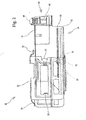
- the lid 60 covers an upper portion of a front face of the mobile-body main body 50, and the lock device 40 is disposed between the front face of the mobile-body main body 50.
- the lock portion 70 is for locking either one of the housing 20 or the mobile member 30 in a state wherein the mobile member 30 is housed in the housing 20.
- the lock portion 70 is provided in the opening portion 21 of the housing 20, and as shown in Fig. 4 , formed in a shape wherein a plan face of a metallic bar is folded in an approximately "U" shape. As shown in Fig. 2 , from a view of a side face, the lock portion 70 is formed so as to be a folded shape in an "L" shape downwardly.
- a knob 80 is rotatably supported to the other of the housing 20 or the mobile member 30, and includes a locking portion 82, which is hooked in the lock portion 70, on one end portion by sandwiching a rotational axis 81 thereof, and an operating portion 83 capable of releasing a locked state of the locking portion 82, which has been locked by being hooked in the lock portion 70 by rotating, on the other end portion.
- the rotational axis 81 is rotationally supported to the mobile member 30 through bearing portions 90 described hereinafter.
- the locking portion 82 extends upwardly from the rotational axis 81, and is formed in a hook shape which is hooked in the bar-like lock portion 70 of the housing 20.
- the operating portion 83 extends downwardly from the rotational axis 81, and protrudes downwardly from the above-mentioned lid 60. Although it is not shown in the figures, the operating portion 83 can be pulled to an immediate front by hooking one's finger.
- the rotational axis 81 of the knob 80 is rotatably supported to the mobile member 30, and the above-mentioned lock portion 70 is provided in the housing 20, they are not limited to the above, and although it is not shown in the figures, the knob 80 may be rotatably supported to the housing 20, and the lock portion 70 may by provided in the mobile member 30.
- the bearing portions 90 protrude toward an immediate front side from right and left of the front face of the mobile-body main body 50 with a pair, and rotatably support both end portions of the rotational axis 81 of the knob 80.
- the bearing portions 90 include each following portion.
- each portion of the bearing portions 90 is not limited to the following (1) and (2).
- a circular hole 91 is formed on one side of one of the bearing portions 90, and rotatably supports one end portion of the rotational axis 81 of the knob 80.
- the circular hole 91 is formed in a "U" shape of a cross-sectional surface whose immediate front side is open, and formed in an approximately circular shape by covering an opening end by the cover 100 described hereinafter.
- an elongate hole 92 is formed on one side of the other of the bearing portions 90, and as shown in Figs. 1 and 7 , the elongate hole 92 movably supports the other end portion of the rotational axis 81 along a moving direction, i.e., a sliding direction of the mobile member 30.
- the elongate hole 92 is formed in a "U" shape of a cross-sectional surface whose immediate front side is open, and formed in an approximately oval shape by covering an opening end by the cover 100 described hereinafter.
- the circular hole 91 is formed, and on one side of the other of the bearing portions 90, the elongate hole 92 is formed.
- the holes are not limited to the above, and the elongate hole 92 may be formed on both sides of the bearing portions 90.
- the cover 100 is for preventing the rotational axis 81 of the knob 80 from falling out of the bearing portions 90 by covering an immediate front side of the bearing portions 90 on both sides, and fixed to the front face of the mobile-body main body 50.
- the return spring 110 is for urging the locking portion 82 toward a direction of being hooked in the lock portion 70.
- a clockwise rotational force is provided as a center of the rotational axis 81.
- the return spring 110 also serves as urging means.
- the above-mentioned urging means is for urging the other end portion of the rotational axis 81, which has been fitted in the elongate hole 92, toward a position of an immediate front side of the elongate hole 92.
- the return spring 110 also serves as the urging means, this is not limited to the above, and the return spring 110 and the urging means may be provided separately.
- the rotation blocking portion 120 is for blocking a rotation of the knob 80 when the other end portion of the rotational axis 81, which has been fitted in the elongate hole 92, moves toward the deep side of the elongate hole 92 against an urging force of the return spring 110 also serving as the urging means.
- the rotation blocking portion 120 abuts against the locking portion 82.
- the rotation blocking portion 120 is notched at a front margin on an immediate front side of the mobile-body main body 50 in a concave shape downwardly from an upper margin thereof, and a width of the notch is set larger than a horizontal width of the locking portion 82 of the knob 80. Then, as shown in Fig. 1 , the rotation blocking portion 120 blocks the rotation of the knob 80 by abutting a bottom of the notch of the concave shape against the locking portion 82 of the knob 80.
- the rotation blocking portion 120 abuts against the locking portion 82 of the knob 80, this is not limited to the above, and the operating portion 83 of the knob 80 may abut. Also, although the rotation blocking portion 120 is formed by notching the mobile-body main body 50, this is not limited to the above, and the rotation blocking portion 120 may be a separate part from the mobile-body main body 50.
- the mobile member 30 is locked in a housed state by the lock device 40.
- the hook-shaped locking portion 82 of the knob 80 is hooked in the bar-like lock portion 70 of the housing 20.
- the mobile member 30 may be pulled out to an immediate front of the housing 20 by releasing a locked state of the lock device 40.
- the locking portion 82 of the knob 80 is fitted in the concave rotation blocking portion 120 of the housing 20, and as shown in Fig. 1 , the bottom of the concave notch of the locking portion 82 abuts against the locking portion 82 of the knob 80, so that the rotation of the knob 80 is blocked, and the locked state of the lock device 40 is maintained.
Landscapes
- Engineering & Computer Science (AREA)
- Mechanical Engineering (AREA)
- Vehicle Step Arrangements And Article Storage (AREA)
- Lock And Its Accessories (AREA)
Claims (4)
- Mécanisme de verrouillage pour un élément mobile (30), comprenant:une base;un élément mobile (30) supporté de manière mobile à la base; etun dispositif de verrouillage (40) placé entre la base et l'élément mobile (30) destiné à verrouiller l'élément mobile (30), le dispositif de verrouillage (40) comprenant:une partie de verrouillage (70) ménagée soit dans l'une de la base ou de l'élément mobile (30);un bouton (80) supporté de manière rotative à l'autre de la base ou de l'élément mobile (30) et comportant une partie de fermeture (82) s'accrochant à la partie de verrouillage (70) sur une partie d'extrémité par rapport à un axe de rotation (81) du bouton (80), et une partie de commande (83) capable de débloquer un état verrouillé de la partie de fermeture (82) qui a été verrouillée en l'accrochant à la partie de verrouillage (70) par rotation, et ménagée sur l'autre partie d'extrémité; etun ressort de rappel (110) pour pousser la partie de fermeture (82) vers une direction accrochée à la partie de verrouillage (70),en ce que le dispositif de verrouillage (40) comprend:un trou oblong (92) pour supporter de manière mobile au moins une partie d'extrémité de l'axe de rotation (81) dans une direction du mouvement de l'élément mobile (30);un dispositif de poussée pour pousser ladite partie d'extrémité de l'axe de rotation (81) vers une position d'un côté avant du trou oblong (92); etune partie de blocage de rotation (120) pour bloquer une rotation du bouton (80) lorsque ladite partie d'extrémité de l'axe de rotation (81) se déplace vers un côté profond du trou oblong (92) contre une force de poussée du dispositif de poussée.
- Mécanisme de verrouillage d'un élément mobile (30) selon la revendication 1, en ce que le ressort de rappel (110) sert également de dispositif de poussée.
- Mécanisme de verrouillage d'un élément mobile (30) selon la revendication 1 ou 2, en ce que la partie de blocage de rotation (120) bute contre la partie de fermeture (82).
- Mécanisme de verrouillage d'un élément mobile (30) selon l'une des revendications 1 à 3, en ce que l'élément mobile (30) est disposé de façon à faire saillie d'un arrière vers un avant du véhicule, et dans un état dans lequel la partie de fermeture (82) est verrouillée dans la partie de verrouillage (70), lorsque l'élément mobile (30) essaie de se déplacer dans une direction saillante, ladite partie d'extrémité de l'axe de rotation (81) peut se déplacer vers le côté profond du trou oblong (92).
Applications Claiming Priority (2)
| Application Number | Priority Date | Filing Date | Title |
|---|---|---|---|
| JP2008295161A JP5336156B2 (ja) | 2008-11-19 | 2008-11-19 | 移動体のロック機構 |
| PCT/JP2009/069437 WO2010058752A1 (fr) | 2008-11-19 | 2009-11-16 | Mécanisme de verrouillage d’un objet mobile |
Publications (3)
| Publication Number | Publication Date |
|---|---|
| EP2354397A1 EP2354397A1 (fr) | 2011-08-10 |
| EP2354397A4 EP2354397A4 (fr) | 2014-10-29 |
| EP2354397B1 true EP2354397B1 (fr) | 2016-01-13 |
Family
ID=42198192
Family Applications (1)
| Application Number | Title | Priority Date | Filing Date |
|---|---|---|---|
| EP09827533.2A Not-in-force EP2354397B1 (fr) | 2008-11-19 | 2009-11-16 | Mécanisme de verrouillage d un objet mobile |
Country Status (6)
| Country | Link |
|---|---|
| US (1) | US9080353B2 (fr) |
| EP (1) | EP2354397B1 (fr) |
| JP (1) | JP5336156B2 (fr) |
| KR (1) | KR101172576B1 (fr) |
| CN (1) | CN102216548B (fr) |
| WO (1) | WO2010058752A1 (fr) |
Families Citing this family (14)
| Publication number | Priority date | Publication date | Assignee | Title |
|---|---|---|---|---|
| JP5823792B2 (ja) * | 2011-09-22 | 2015-11-25 | 株式会社ニフコ | ロック装置 |
| DE102013006826A1 (de) | 2013-04-22 | 2014-10-23 | Illinois Tool Works Inc. | Türgriffanordnung für ein Automobil |
| EP3087235B1 (fr) * | 2013-12-23 | 2020-12-02 | Faurecia Interior Systems India Pvt. Ltd. | Dispositif de verrouillage comprenant un élément de verrouillage mobile dans une première direction et dans une seconde direction |
| KR20170030148A (ko) * | 2015-09-08 | 2017-03-17 | 주식회사 니프코코리아 | 콘솔박스 개폐용 후크 |
| FR3058960B1 (fr) * | 2016-11-21 | 2021-03-26 | Peugeot Citroen Automobiles Sa | Tiroir de rangement avec systeme de verrouillage et bouton poussoir |
| DE102019204698A1 (de) | 2018-04-10 | 2019-10-10 | Faurecia Innenraum Systeme Gmbh | Verriegelungsmechanismus für ein Ablagefach mit einem Deckel und Ablagefach mit entsprechendem Verriegelungsmechanismus |
| CN109051393B (zh) * | 2018-08-15 | 2024-09-06 | 四川宏华石油设备有限公司 | 一种柔性水罐锁紧装置 |
| CN109051394B (zh) * | 2018-08-15 | 2024-09-06 | 四川宏华石油设备有限公司 | 一种柔性水罐锁紧装置 |
| EP3990727B1 (fr) * | 2020-08-19 | 2023-05-03 | Weber GmbH & Co. KG Kunststofftechnick - Formenbau | Dispositif de verrouillage destiné à un récipient ou un couvercle, en particulier de véhicules automobiles, et pouvant être actionné entre une position fermée et une position ouverte |
| FR3137638A1 (fr) * | 2022-07-11 | 2024-01-12 | Psa Automobiles Sa | Boîte de rangement pour véhicule automobile comprenant un dispositif de fermeture d’un tiroir |
| USD1058613S1 (en) | 2022-11-29 | 2025-01-21 | Calmer Holding Company, Llc | Limiter plates |
| US12402564B2 (en) | 2022-11-29 | 2025-09-02 | Calmer Holding Company, Llc | Over-center latch with mount, base plate, lever, and center pin for combine concaves |
| US12225855B2 (en) * | 2022-11-29 | 2025-02-18 | Calmer Holding Company, Llc | Over-center latch with mount, base plate, lever, and center pin for combine concaves |
| US12426548B2 (en) | 2022-12-16 | 2025-09-30 | Calmer Holding Company, Llc | Systems for regulating the flow of material other than grain through common concaves while simultaneously equalizing the flow of grain through common concaves |
Family Cites Families (25)
| Publication number | Priority date | Publication date | Assignee | Title |
|---|---|---|---|---|
| US1840037A (en) * | 1928-07-04 | 1932-01-05 | Johansson Johan Petter | Lock |
| US2029199A (en) * | 1935-04-23 | 1936-01-28 | Segar Lee | Handle |
| US2634997A (en) * | 1949-11-04 | 1953-04-14 | William R Gallowitz | Spring latch mechanism |
| US2773715A (en) * | 1954-10-22 | 1956-12-11 | Chicago Forging & Mfg Co | Hood latch |
| US4003593A (en) * | 1976-02-23 | 1977-01-18 | Herbert Wilzig | Push door-latch opener |
| JPH0335020Y2 (fr) * | 1985-04-28 | 1991-07-24 | ||
| JPS646482A (en) * | 1987-06-26 | 1989-01-11 | Ohi Seisakusho Co Ltd | Door lock apparatus for vehicle |
| JPH0547234Y2 (fr) * | 1988-03-16 | 1993-12-13 | ||
| JPH0276546A (ja) | 1988-09-12 | 1990-03-15 | Funai Electric Co Ltd | 飯 |
| JPH0276546U (fr) | 1988-11-30 | 1990-06-12 | ||
| JPH0628417Y2 (ja) | 1989-08-15 | 1994-08-03 | 本州製紙株式会社 | 宅配便用保冷ケース |
| JPH0547234U (ja) | 1991-07-10 | 1993-06-22 | ナショナル住宅産業株式会社 | 防水パン |
| JP2565196Y2 (ja) | 1992-02-18 | 1998-03-11 | スズキ株式会社 | グローブボックス用ロック装置 |
| DE4336619C1 (de) * | 1993-10-27 | 1995-02-09 | Porsche Ag | Verschluß für ein Deckelelement eines Fahrzeuges, insbesondere für einen Handschuhkastendeckel eines Kraftfahrzeuges |
| US5630630A (en) * | 1995-07-11 | 1997-05-20 | Strattec Security Corporation | Glove compartment latch mechanism |
| CN2312295Y (zh) * | 1997-08-21 | 1999-03-31 | 张士忠 | 一种推拉式门把手 |
| JP2000110433A (ja) | 1998-10-02 | 2000-04-18 | Mitsubishi Motors Corp | グローブボックス開放防止装置 |
| IT1309802B1 (it) | 1999-05-07 | 2002-01-30 | Valeo Sicurezza Abitacolo Spa | Maniglia per una porta di un veicolo |
| DE19929022C2 (de) | 1999-06-25 | 2001-06-07 | Huf Huelsbeck & Fuerst Gmbh | Türaußengriff, insbesondere für Fahrzeuge |
| CN2418216Y (zh) * | 1999-12-29 | 2001-02-07 | 范芳溢 | 把手锁具 |
| DE10015887C1 (de) | 2000-03-30 | 2002-01-17 | Huf Huelsbeck & Fuerst Gmbh | Zugangssystem für ein Fahrzeug |
| JP4462768B2 (ja) * | 2001-01-19 | 2010-05-12 | 株式会社ニフコ | 安全機能付ロック装置及び乗物用収納装置 |
| US7152893B2 (en) * | 2004-08-23 | 2006-12-26 | Key Plastics, Llc | Handle assembly with dual latch feature |
| CN201027435Y (zh) * | 2007-03-27 | 2008-02-27 | 白宝鲲 | 门窗把手动作防误装置 |
| JP2008295161A (ja) | 2007-05-23 | 2008-12-04 | Daikin Ind Ltd | 電力変換装置 |
-
2008
- 2008-11-19 JP JP2008295161A patent/JP5336156B2/ja active Active
-
2009
- 2009-11-16 US US12/998,661 patent/US9080353B2/en not_active Expired - Fee Related
- 2009-11-16 EP EP09827533.2A patent/EP2354397B1/fr not_active Not-in-force
- 2009-11-16 WO PCT/JP2009/069437 patent/WO2010058752A1/fr not_active Ceased
- 2009-11-16 CN CN200980146283.8A patent/CN102216548B/zh not_active Expired - Fee Related
- 2009-11-19 KR KR1020090111850A patent/KR101172576B1/ko not_active Expired - Fee Related
Also Published As
| Publication number | Publication date |
|---|---|
| KR101172576B1 (ko) | 2012-08-08 |
| KR20100056409A (ko) | 2010-05-27 |
| EP2354397A1 (fr) | 2011-08-10 |
| US9080353B2 (en) | 2015-07-14 |
| US20110241358A1 (en) | 2011-10-06 |
| JP5336156B2 (ja) | 2013-11-06 |
| JP2010121336A (ja) | 2010-06-03 |
| WO2010058752A1 (fr) | 2010-05-27 |
| CN102216548B (zh) | 2014-06-04 |
| EP2354397A4 (fr) | 2014-10-29 |
| CN102216548A (zh) | 2011-10-12 |
Similar Documents
| Publication | Publication Date | Title |
|---|---|---|
| EP2354397B1 (fr) | Mécanisme de verrouillage d un objet mobile | |
| US8123261B2 (en) | Lid lock structure of storing box for vehicle | |
| EP2010414B1 (fr) | Systeme de verrouillage destine a un panneau coulissant dispose dans un vehicule | |
| EP2567868A1 (fr) | Boîte de console | |
| KR20090062177A (ko) | 자동차 암레스트 콘솔박스의 고정 구조 | |
| CN211731231U (zh) | 用于车辆的座椅靠背及车辆座椅靠背 | |
| US20090284023A1 (en) | Apparatus for preventing opening of a tray cover for an automobile | |
| KR100442736B1 (ko) | 안전기능을 가지는 로크장치 및 승물용 수납장치 | |
| CN216331782U (zh) | 存储控制台 | |
| JP3545175B2 (ja) | 携帯用コンピュータの周辺装置収納部 | |
| CZ7523U1 (cs) | Držadlo pro dveře nebo víko elektroinstalační skříně | |
| JP2000006721A (ja) | 車体設置型の多目的ロープ装置 | |
| KR100598517B1 (ko) | 차량의 트레이장치 | |
| JP4137705B2 (ja) | 自動車のトランクロック装置 | |
| JPH0425394Y2 (fr) | ||
| CN211549252U (zh) | 针对带盖部的储物箱的闭锁机构和具有对应的闭锁机构的储物箱 | |
| CN223984391U (zh) | 一种抽屉式车载保险箱 | |
| JP2532003Y2 (ja) | 車載用収納装置 | |
| JP5508152B2 (ja) | 車両用物入れ | |
| JP4324440B2 (ja) | ロック装置 | |
| KR101637600B1 (ko) | 차량용 푸쉬-오픈 타입의 트레이 어셈블리 | |
| KR100828611B1 (ko) | 차량 트레이의 잠금 구조 | |
| JP2019044510A (ja) | ロック装置 | |
| JP2004074856A (ja) | スライドドアのポケット構造 | |
| JP2003320901A (ja) | 自動車用小物入 |
Legal Events
| Date | Code | Title | Description |
|---|---|---|---|
| PUAI | Public reference made under article 153(3) epc to a published international application that has entered the european phase |
Free format text: ORIGINAL CODE: 0009012 |
|
| 17P | Request for examination filed |
Effective date: 20110524 |
|
| AK | Designated contracting states |
Kind code of ref document: A1 Designated state(s): AT BE BG CH CY CZ DE DK EE ES FI FR GB GR HR HU IE IS IT LI LT LU LV MC MK MT NL NO PL PT RO SE SI SK SM TR |
|
| DAX | Request for extension of the european patent (deleted) | ||
| A4 | Supplementary search report drawn up and despatched |
Effective date: 20140929 |
|
| RIC1 | Information provided on ipc code assigned before grant |
Ipc: E05C 21/00 20060101AFI20140925BHEP Ipc: B60R 7/06 20060101ALI20140925BHEP Ipc: E05C 3/14 20060101ALI20140925BHEP |
|
| REG | Reference to a national code |
Ref country code: DE Ref legal event code: R079 Ref document number: 602009035898 Country of ref document: DE Free format text: PREVIOUS MAIN CLASS: E05C0021000000 Ipc: E05B0077060000 |
|
| RIC1 | Information provided on ipc code assigned before grant |
Ipc: E05B 85/14 20140101ALI20150430BHEP Ipc: E05B 83/30 20140101ALI20150430BHEP Ipc: E05B 77/06 20140101AFI20150430BHEP Ipc: E05B 83/32 20140101ALI20150430BHEP Ipc: B60R 7/06 20060101ALI20150430BHEP |
|
| GRAP | Despatch of communication of intention to grant a patent |
Free format text: ORIGINAL CODE: EPIDOSNIGR1 |
|
| INTG | Intention to grant announced |
Effective date: 20150616 |
|
| GRAP | Despatch of communication of intention to grant a patent |
Free format text: ORIGINAL CODE: EPIDOSNIGR1 |
|
| INTG | Intention to grant announced |
Effective date: 20150805 |
|
| GRAS | Grant fee paid |
Free format text: ORIGINAL CODE: EPIDOSNIGR3 |
|
| GRAA | (expected) grant |
Free format text: ORIGINAL CODE: 0009210 |
|
| RAP1 | Party data changed (applicant data changed or rights of an application transferred) |
Owner name: NIFCO INC. |
|
| AK | Designated contracting states |
Kind code of ref document: B1 Designated state(s): AT BE BG CH CY CZ DE DK EE ES FI FR GB GR HR HU IE IS IT LI LT LU LV MC MK MT NL NO PL PT RO SE SI SK SM TR |
|
| REG | Reference to a national code |
Ref country code: GB Ref legal event code: FG4D |
|
| REG | Reference to a national code |
Ref country code: CH Ref legal event code: EP |
|
| REG | Reference to a national code |
Ref country code: IE Ref legal event code: FG4D |
|
| REG | Reference to a national code |
Ref country code: AT Ref legal event code: REF Ref document number: 770641 Country of ref document: AT Kind code of ref document: T Effective date: 20160215 |
|
| REG | Reference to a national code |
Ref country code: DE Ref legal event code: R096 Ref document number: 602009035898 Country of ref document: DE |
|
| REG | Reference to a national code |
Ref country code: LT Ref legal event code: MG4D |
|
| REG | Reference to a national code |
Ref country code: NL Ref legal event code: MP Effective date: 20160113 |
|
| REG | Reference to a national code |
Ref country code: AT Ref legal event code: MK05 Ref document number: 770641 Country of ref document: AT Kind code of ref document: T Effective date: 20160113 |
|
| PG25 | Lapsed in a contracting state [announced via postgrant information from national office to epo] |
Ref country code: NL Free format text: LAPSE BECAUSE OF FAILURE TO SUBMIT A TRANSLATION OF THE DESCRIPTION OR TO PAY THE FEE WITHIN THE PRESCRIBED TIME-LIMIT Effective date: 20160113 |
|
| PG25 | Lapsed in a contracting state [announced via postgrant information from national office to epo] |
Ref country code: IT Free format text: LAPSE BECAUSE OF FAILURE TO SUBMIT A TRANSLATION OF THE DESCRIPTION OR TO PAY THE FEE WITHIN THE PRESCRIBED TIME-LIMIT Effective date: 20160113 Ref country code: NO Free format text: LAPSE BECAUSE OF FAILURE TO SUBMIT A TRANSLATION OF THE DESCRIPTION OR TO PAY THE FEE WITHIN THE PRESCRIBED TIME-LIMIT Effective date: 20160413 Ref country code: GR Free format text: LAPSE BECAUSE OF FAILURE TO SUBMIT A TRANSLATION OF THE DESCRIPTION OR TO PAY THE FEE WITHIN THE PRESCRIBED TIME-LIMIT Effective date: 20160414 Ref country code: ES Free format text: LAPSE BECAUSE OF FAILURE TO SUBMIT A TRANSLATION OF THE DESCRIPTION OR TO PAY THE FEE WITHIN THE PRESCRIBED TIME-LIMIT Effective date: 20160113 Ref country code: FI Free format text: LAPSE BECAUSE OF FAILURE TO SUBMIT A TRANSLATION OF THE DESCRIPTION OR TO PAY THE FEE WITHIN THE PRESCRIBED TIME-LIMIT Effective date: 20160113 Ref country code: HR Free format text: LAPSE BECAUSE OF FAILURE TO SUBMIT A TRANSLATION OF THE DESCRIPTION OR TO PAY THE FEE WITHIN THE PRESCRIBED TIME-LIMIT Effective date: 20160113 |
|
| PG25 | Lapsed in a contracting state [announced via postgrant information from national office to epo] |
Ref country code: IS Free format text: LAPSE BECAUSE OF FAILURE TO SUBMIT A TRANSLATION OF THE DESCRIPTION OR TO PAY THE FEE WITHIN THE PRESCRIBED TIME-LIMIT Effective date: 20160513 Ref country code: PT Free format text: LAPSE BECAUSE OF FAILURE TO SUBMIT A TRANSLATION OF THE DESCRIPTION OR TO PAY THE FEE WITHIN THE PRESCRIBED TIME-LIMIT Effective date: 20160513 Ref country code: LV Free format text: LAPSE BECAUSE OF FAILURE TO SUBMIT A TRANSLATION OF THE DESCRIPTION OR TO PAY THE FEE WITHIN THE PRESCRIBED TIME-LIMIT Effective date: 20160113 Ref country code: PL Free format text: LAPSE BECAUSE OF FAILURE TO SUBMIT A TRANSLATION OF THE DESCRIPTION OR TO PAY THE FEE WITHIN THE PRESCRIBED TIME-LIMIT Effective date: 20160113 Ref country code: LT Free format text: LAPSE BECAUSE OF FAILURE TO SUBMIT A TRANSLATION OF THE DESCRIPTION OR TO PAY THE FEE WITHIN THE PRESCRIBED TIME-LIMIT Effective date: 20160113 Ref country code: SE Free format text: LAPSE BECAUSE OF FAILURE TO SUBMIT A TRANSLATION OF THE DESCRIPTION OR TO PAY THE FEE WITHIN THE PRESCRIBED TIME-LIMIT Effective date: 20160113 Ref country code: AT Free format text: LAPSE BECAUSE OF FAILURE TO SUBMIT A TRANSLATION OF THE DESCRIPTION OR TO PAY THE FEE WITHIN THE PRESCRIBED TIME-LIMIT Effective date: 20160113 |
|
| REG | Reference to a national code |
Ref country code: DE Ref legal event code: R097 Ref document number: 602009035898 Country of ref document: DE Ref country code: FR Ref legal event code: PLFP Year of fee payment: 8 |
|
| PG25 | Lapsed in a contracting state [announced via postgrant information from national office to epo] |
Ref country code: EE Free format text: LAPSE BECAUSE OF FAILURE TO SUBMIT A TRANSLATION OF THE DESCRIPTION OR TO PAY THE FEE WITHIN THE PRESCRIBED TIME-LIMIT Effective date: 20160113 Ref country code: DK Free format text: LAPSE BECAUSE OF FAILURE TO SUBMIT A TRANSLATION OF THE DESCRIPTION OR TO PAY THE FEE WITHIN THE PRESCRIBED TIME-LIMIT Effective date: 20160113 |
|
| PLBE | No opposition filed within time limit |
Free format text: ORIGINAL CODE: 0009261 |
|
| STAA | Information on the status of an ep patent application or granted ep patent |
Free format text: STATUS: NO OPPOSITION FILED WITHIN TIME LIMIT |
|
| PG25 | Lapsed in a contracting state [announced via postgrant information from national office to epo] |
Ref country code: CZ Free format text: LAPSE BECAUSE OF FAILURE TO SUBMIT A TRANSLATION OF THE DESCRIPTION OR TO PAY THE FEE WITHIN THE PRESCRIBED TIME-LIMIT Effective date: 20160113 Ref country code: SM Free format text: LAPSE BECAUSE OF FAILURE TO SUBMIT A TRANSLATION OF THE DESCRIPTION OR TO PAY THE FEE WITHIN THE PRESCRIBED TIME-LIMIT Effective date: 20160113 Ref country code: SK Free format text: LAPSE BECAUSE OF FAILURE TO SUBMIT A TRANSLATION OF THE DESCRIPTION OR TO PAY THE FEE WITHIN THE PRESCRIBED TIME-LIMIT Effective date: 20160113 Ref country code: RO Free format text: LAPSE BECAUSE OF FAILURE TO SUBMIT A TRANSLATION OF THE DESCRIPTION OR TO PAY THE FEE WITHIN THE PRESCRIBED TIME-LIMIT Effective date: 20160113 |
|
| 26N | No opposition filed |
Effective date: 20161014 |
|
| PG25 | Lapsed in a contracting state [announced via postgrant information from national office to epo] |
Ref country code: BE Free format text: LAPSE BECAUSE OF FAILURE TO SUBMIT A TRANSLATION OF THE DESCRIPTION OR TO PAY THE FEE WITHIN THE PRESCRIBED TIME-LIMIT Effective date: 20160113 |
|
| PG25 | Lapsed in a contracting state [announced via postgrant information from national office to epo] |
Ref country code: BG Free format text: LAPSE BECAUSE OF FAILURE TO SUBMIT A TRANSLATION OF THE DESCRIPTION OR TO PAY THE FEE WITHIN THE PRESCRIBED TIME-LIMIT Effective date: 20160413 Ref country code: SI Free format text: LAPSE BECAUSE OF FAILURE TO SUBMIT A TRANSLATION OF THE DESCRIPTION OR TO PAY THE FEE WITHIN THE PRESCRIBED TIME-LIMIT Effective date: 20160113 |
|
| REG | Reference to a national code |
Ref country code: CH Ref legal event code: PL |
|
| PG25 | Lapsed in a contracting state [announced via postgrant information from national office to epo] |
Ref country code: LI Free format text: LAPSE BECAUSE OF NON-PAYMENT OF DUE FEES Effective date: 20161130 Ref country code: CH Free format text: LAPSE BECAUSE OF NON-PAYMENT OF DUE FEES Effective date: 20161130 |
|
| REG | Reference to a national code |
Ref country code: IE Ref legal event code: MM4A |
|
| PG25 | Lapsed in a contracting state [announced via postgrant information from national office to epo] |
Ref country code: LU Free format text: LAPSE BECAUSE OF NON-PAYMENT OF DUE FEES Effective date: 20161130 |
|
| REG | Reference to a national code |
Ref country code: FR Ref legal event code: PLFP Year of fee payment: 9 |
|
| PG25 | Lapsed in a contracting state [announced via postgrant information from national office to epo] |
Ref country code: IE Free format text: LAPSE BECAUSE OF NON-PAYMENT OF DUE FEES Effective date: 20161116 |
|
| PG25 | Lapsed in a contracting state [announced via postgrant information from national office to epo] |
Ref country code: HU Free format text: LAPSE BECAUSE OF FAILURE TO SUBMIT A TRANSLATION OF THE DESCRIPTION OR TO PAY THE FEE WITHIN THE PRESCRIBED TIME-LIMIT; INVALID AB INITIO Effective date: 20091116 Ref country code: CY Free format text: LAPSE BECAUSE OF FAILURE TO SUBMIT A TRANSLATION OF THE DESCRIPTION OR TO PAY THE FEE WITHIN THE PRESCRIBED TIME-LIMIT Effective date: 20160113 |
|
| PG25 | Lapsed in a contracting state [announced via postgrant information from national office to epo] |
Ref country code: MC Free format text: LAPSE BECAUSE OF FAILURE TO SUBMIT A TRANSLATION OF THE DESCRIPTION OR TO PAY THE FEE WITHIN THE PRESCRIBED TIME-LIMIT Effective date: 20160113 Ref country code: MK Free format text: LAPSE BECAUSE OF FAILURE TO SUBMIT A TRANSLATION OF THE DESCRIPTION OR TO PAY THE FEE WITHIN THE PRESCRIBED TIME-LIMIT Effective date: 20160113 Ref country code: TR Free format text: LAPSE BECAUSE OF FAILURE TO SUBMIT A TRANSLATION OF THE DESCRIPTION OR TO PAY THE FEE WITHIN THE PRESCRIBED TIME-LIMIT Effective date: 20160113 |
|
| PG25 | Lapsed in a contracting state [announced via postgrant information from national office to epo] |
Ref country code: MT Free format text: LAPSE BECAUSE OF NON-PAYMENT OF DUE FEES Effective date: 20161116 |
|
| REG | Reference to a national code |
Ref country code: FR Ref legal event code: PLFP Year of fee payment: 10 |
|
| PGFP | Annual fee paid to national office [announced via postgrant information from national office to epo] |
Ref country code: GB Payment date: 20201104 Year of fee payment: 12 Ref country code: DE Payment date: 20201103 Year of fee payment: 12 Ref country code: FR Payment date: 20201013 Year of fee payment: 12 |
|
| REG | Reference to a national code |
Ref country code: DE Ref legal event code: R119 Ref document number: 602009035898 Country of ref document: DE |
|
| GBPC | Gb: european patent ceased through non-payment of renewal fee |
Effective date: 20211116 |
|
| PG25 | Lapsed in a contracting state [announced via postgrant information from national office to epo] |
Ref country code: GB Free format text: LAPSE BECAUSE OF NON-PAYMENT OF DUE FEES Effective date: 20211116 Ref country code: DE Free format text: LAPSE BECAUSE OF NON-PAYMENT OF DUE FEES Effective date: 20220601 |
|
| PG25 | Lapsed in a contracting state [announced via postgrant information from national office to epo] |
Ref country code: FR Free format text: LAPSE BECAUSE OF NON-PAYMENT OF DUE FEES Effective date: 20211130 |