EP2353718A2 - Flüssigprobenanalysegerät - Google Patents
Flüssigprobenanalysegerät Download PDFInfo
- Publication number
- EP2353718A2 EP2353718A2 EP11000876A EP11000876A EP2353718A2 EP 2353718 A2 EP2353718 A2 EP 2353718A2 EP 11000876 A EP11000876 A EP 11000876A EP 11000876 A EP11000876 A EP 11000876A EP 2353718 A2 EP2353718 A2 EP 2353718A2
- Authority
- EP
- European Patent Office
- Prior art keywords
- flow path
- blood
- liquid sample
- concave portion
- liquid
- Prior art date
- Legal status (The legal status is an assumption and is not a legal conclusion. Google has not performed a legal analysis and makes no representation as to the accuracy of the status listed.)
- Withdrawn
Links
- 239000007788 liquid Substances 0.000 title claims abstract description 108
- 238000001514 detection method Methods 0.000 claims abstract description 55
- 239000000463 material Substances 0.000 claims description 24
- 230000001070 adhesive effect Effects 0.000 claims description 22
- 239000000853 adhesive Substances 0.000 claims description 21
- 230000000903 blocking effect Effects 0.000 claims description 2
- 239000012790 adhesive layer Substances 0.000 claims 3
- 210000004369 blood Anatomy 0.000 description 106
- 239000008280 blood Substances 0.000 description 106
- 239000003153 chemical reaction reagent Substances 0.000 description 56
- 239000000523 sample Substances 0.000 description 41
- 238000011144 upstream manufacturing Methods 0.000 description 36
- 239000010408 film Substances 0.000 description 24
- 238000005259 measurement Methods 0.000 description 18
- 238000002156 mixing Methods 0.000 description 16
- 238000000034 method Methods 0.000 description 13
- 210000004027 cell Anatomy 0.000 description 11
- 238000000605 extraction Methods 0.000 description 10
- 239000000758 substrate Substances 0.000 description 10
- 238000003780 insertion Methods 0.000 description 9
- 230000037431 insertion Effects 0.000 description 9
- 238000004820 blood count Methods 0.000 description 7
- 210000000601 blood cell Anatomy 0.000 description 6
- 238000010586 diagram Methods 0.000 description 6
- 230000017531 blood circulation Effects 0.000 description 5
- 238000004364 calculation method Methods 0.000 description 5
- 239000007787 solid Substances 0.000 description 4
- BQCADISMDOOEFD-UHFFFAOYSA-N Silver Chemical compound [Ag] BQCADISMDOOEFD-UHFFFAOYSA-N 0.000 description 3
- 238000004519 manufacturing process Methods 0.000 description 3
- 238000000465 moulding Methods 0.000 description 3
- 239000011347 resin Substances 0.000 description 3
- 229920005989 resin Polymers 0.000 description 3
- 229910052709 silver Inorganic materials 0.000 description 3
- 239000004332 silver Substances 0.000 description 3
- 238000003860 storage Methods 0.000 description 3
- OKTJSMMVPCPJKN-UHFFFAOYSA-N Carbon Chemical compound [C] OKTJSMMVPCPJKN-UHFFFAOYSA-N 0.000 description 2
- 238000004458 analytical method Methods 0.000 description 2
- 210000001772 blood platelet Anatomy 0.000 description 2
- 229910052799 carbon Inorganic materials 0.000 description 2
- 230000002542 deteriorative effect Effects 0.000 description 2
- 239000012470 diluted sample Substances 0.000 description 2
- 230000000694 effects Effects 0.000 description 2
- 210000003743 erythrocyte Anatomy 0.000 description 2
- 238000009413 insulation Methods 0.000 description 2
- 210000000265 leukocyte Anatomy 0.000 description 2
- 238000007650 screen-printing Methods 0.000 description 2
- 238000007789 sealing Methods 0.000 description 2
- 238000004544 sputter deposition Methods 0.000 description 2
- 238000003756 stirring Methods 0.000 description 2
- 239000000126 substance Substances 0.000 description 2
- 238000009423 ventilation Methods 0.000 description 2
- 239000004743 Polypropylene Substances 0.000 description 1
- 229910052782 aluminium Inorganic materials 0.000 description 1
- XAGFODPZIPBFFR-UHFFFAOYSA-N aluminium Chemical compound [Al] XAGFODPZIPBFFR-UHFFFAOYSA-N 0.000 description 1
- 230000004323 axial length Effects 0.000 description 1
- 238000004159 blood analysis Methods 0.000 description 1
- 210000001124 body fluid Anatomy 0.000 description 1
- 239000010839 body fluid Substances 0.000 description 1
- 238000007865 diluting Methods 0.000 description 1
- 239000000428 dust Substances 0.000 description 1
- 238000005530 etching Methods 0.000 description 1
- 238000010438 heat treatment Methods 0.000 description 1
- 238000001746 injection moulding Methods 0.000 description 1
- 238000005304 joining Methods 0.000 description 1
- 238000013208 measuring procedure Methods 0.000 description 1
- 239000000155 melt Substances 0.000 description 1
- 229910052751 metal Inorganic materials 0.000 description 1
- 239000002184 metal Substances 0.000 description 1
- 238000005459 micromachining Methods 0.000 description 1
- 239000000203 mixture Substances 0.000 description 1
- 230000003287 optical effect Effects 0.000 description 1
- 229920003229 poly(methyl methacrylate) Polymers 0.000 description 1
- 239000004926 polymethyl methacrylate Substances 0.000 description 1
- -1 polypropylene Polymers 0.000 description 1
- 229920001155 polypropylene Polymers 0.000 description 1
- 230000000717 retained effect Effects 0.000 description 1
- 239000000243 solution Substances 0.000 description 1
- 239000010409 thin film Substances 0.000 description 1
- 239000002699 waste material Substances 0.000 description 1
Images







Classifications
-
- G—PHYSICS
- G01—MEASURING; TESTING
- G01N—INVESTIGATING OR ANALYSING MATERIALS BY DETERMINING THEIR CHEMICAL OR PHYSICAL PROPERTIES
- G01N35/00—Automatic analysis not limited to methods or materials provided for in any single one of groups G01N1/00 - G01N33/00; Handling materials therefor
- G01N35/10—Devices for transferring samples or any liquids to, in, or from, the analysis apparatus, e.g. suction devices, injection devices
- G01N35/1095—Devices for transferring samples or any liquids to, in, or from, the analysis apparatus, e.g. suction devices, injection devices for supplying the samples to flow-through analysers
-
- B—PERFORMING OPERATIONS; TRANSPORTING
- B01—PHYSICAL OR CHEMICAL PROCESSES OR APPARATUS IN GENERAL
- B01L—CHEMICAL OR PHYSICAL LABORATORY APPARATUS FOR GENERAL USE
- B01L3/00—Containers or dishes for laboratory use, e.g. laboratory glassware; Droppers
- B01L3/50—Containers for the purpose of retaining a material to be analysed, e.g. test tubes
- B01L3/502—Containers for the purpose of retaining a material to be analysed, e.g. test tubes with fluid transport, e.g. in multi-compartment structures
- B01L3/5027—Containers for the purpose of retaining a material to be analysed, e.g. test tubes with fluid transport, e.g. in multi-compartment structures by integrated microfluidic structures, i.e. dimensions of channels and chambers are such that surface tension forces are important, e.g. lab-on-a-chip
- B01L3/502715—Containers for the purpose of retaining a material to be analysed, e.g. test tubes with fluid transport, e.g. in multi-compartment structures by integrated microfluidic structures, i.e. dimensions of channels and chambers are such that surface tension forces are important, e.g. lab-on-a-chip characterised by interfacing components, e.g. fluidic, electrical, optical or mechanical interfaces
-
- B—PERFORMING OPERATIONS; TRANSPORTING
- B01—PHYSICAL OR CHEMICAL PROCESSES OR APPARATUS IN GENERAL
- B01L—CHEMICAL OR PHYSICAL LABORATORY APPARATUS FOR GENERAL USE
- B01L2200/00—Solutions for specific problems relating to chemical or physical laboratory apparatus
- B01L2200/02—Adapting objects or devices to another
- B01L2200/026—Fluid interfacing between devices or objects, e.g. connectors, inlet details
- B01L2200/027—Fluid interfacing between devices or objects, e.g. connectors, inlet details for microfluidic devices
-
- B—PERFORMING OPERATIONS; TRANSPORTING
- B01—PHYSICAL OR CHEMICAL PROCESSES OR APPARATUS IN GENERAL
- B01L—CHEMICAL OR PHYSICAL LABORATORY APPARATUS FOR GENERAL USE
- B01L2200/00—Solutions for specific problems relating to chemical or physical laboratory apparatus
- B01L2200/04—Exchange or ejection of cartridges, containers or reservoirs
-
- B—PERFORMING OPERATIONS; TRANSPORTING
- B01—PHYSICAL OR CHEMICAL PROCESSES OR APPARATUS IN GENERAL
- B01L—CHEMICAL OR PHYSICAL LABORATORY APPARATUS FOR GENERAL USE
- B01L2200/00—Solutions for specific problems relating to chemical or physical laboratory apparatus
- B01L2200/06—Fluid handling related problems
- B01L2200/0684—Venting, avoiding backpressure, avoid gas bubbles
-
- B—PERFORMING OPERATIONS; TRANSPORTING
- B01—PHYSICAL OR CHEMICAL PROCESSES OR APPARATUS IN GENERAL
- B01L—CHEMICAL OR PHYSICAL LABORATORY APPARATUS FOR GENERAL USE
- B01L2300/00—Additional constructional details
- B01L2300/06—Auxiliary integrated devices, integrated components
- B01L2300/0627—Sensor or part of a sensor is integrated
- B01L2300/0636—Integrated biosensor, microarrays
-
- B—PERFORMING OPERATIONS; TRANSPORTING
- B01—PHYSICAL OR CHEMICAL PROCESSES OR APPARATUS IN GENERAL
- B01L—CHEMICAL OR PHYSICAL LABORATORY APPARATUS FOR GENERAL USE
- B01L2300/00—Additional constructional details
- B01L2300/06—Auxiliary integrated devices, integrated components
- B01L2300/0627—Sensor or part of a sensor is integrated
- B01L2300/0645—Electrodes
-
- B—PERFORMING OPERATIONS; TRANSPORTING
- B01—PHYSICAL OR CHEMICAL PROCESSES OR APPARATUS IN GENERAL
- B01L—CHEMICAL OR PHYSICAL LABORATORY APPARATUS FOR GENERAL USE
- B01L2300/00—Additional constructional details
- B01L2300/08—Geometry, shape and general structure
- B01L2300/0809—Geometry, shape and general structure rectangular shaped
-
- B—PERFORMING OPERATIONS; TRANSPORTING
- B01—PHYSICAL OR CHEMICAL PROCESSES OR APPARATUS IN GENERAL
- B01L—CHEMICAL OR PHYSICAL LABORATORY APPARATUS FOR GENERAL USE
- B01L2300/00—Additional constructional details
- B01L2300/08—Geometry, shape and general structure
- B01L2300/0861—Configuration of multiple channels and/or chambers in a single devices
- B01L2300/087—Multiple sequential chambers
-
- B—PERFORMING OPERATIONS; TRANSPORTING
- B01—PHYSICAL OR CHEMICAL PROCESSES OR APPARATUS IN GENERAL
- B01L—CHEMICAL OR PHYSICAL LABORATORY APPARATUS FOR GENERAL USE
- B01L2300/00—Additional constructional details
- B01L2300/08—Geometry, shape and general structure
- B01L2300/0861—Configuration of multiple channels and/or chambers in a single devices
- B01L2300/088—Channel loops
-
- G—PHYSICS
- G01—MEASURING; TESTING
- G01N—INVESTIGATING OR ANALYSING MATERIALS BY DETERMINING THEIR CHEMICAL OR PHYSICAL PROPERTIES
- G01N35/00—Automatic analysis not limited to methods or materials provided for in any single one of groups G01N1/00 - G01N33/00; Handling materials therefor
- G01N2035/00178—Special arrangements of analysers
- G01N2035/00237—Handling microquantities of analyte, e.g. microvalves, capillary networks
-
- G—PHYSICS
- G01—MEASURING; TESTING
- G01N—INVESTIGATING OR ANALYSING MATERIALS BY DETERMINING THEIR CHEMICAL OR PHYSICAL PROPERTIES
- G01N35/00—Automatic analysis not limited to methods or materials provided for in any single one of groups G01N1/00 - G01N33/00; Handling materials therefor
- G01N35/00029—Automatic analysis not limited to methods or materials provided for in any single one of groups G01N1/00 - G01N33/00; Handling materials therefor provided with flat sample substrates, e.g. slides
Definitions
- the present invention relates to a liquid sample analyzer for analyzing a liquid sample such as blood.
- This cartridge detachably attached to a measurement main body.
- This cartridge includes: a flow path for flowing a diluted sample blood which serves as a liquid sample; and a detection part provided in the flow path to measure the sample blood.
- the cartridge includes: a first substrate forming a concave groove on the surface; a second substrate which configures the flow path by covering an opening part of the concave groove when stuck to the first substrate and which forms a detection part contacting to sample blood and a lead line; and an adhesive sheet for joining the first substrate and the second substrate.
- the adhesive sheet is configured to almost entirely cover a surface of the first substrate except for a part corresponding to a place where the detection part is formed. Since the cartridge is configured in this manner, the detection part is contained and arranged in a stepwise concave portion configured by the adhesive sheet and the second substrate in the flow path (see FIG. 12 ).
- an air bubble included in the sample blood has a tendency to stay in the stepwise concave portion formed of the adhesive sheet and the second substrate, and as the result, there is a problem that the air bubble adheres to the detection part.
- the air bubble has adhered to the detection part as described above, there is a problem that a signal from the detection part is varied or the detection part and the liquid sample are insulated from each other to deteriorate a measurement accuracy.
- a method for increasing the buoyancy applied to the air bubble to remove the air bubble by decompressing inside of the flow path to enlarge a size of the air bubble or a method for stirring liquid in the vicinity of the detection part by using a stirring device such as a stirrer in the flow path is considered.
- Patent literature 1 JP2007-17302A
- the present invention is made to solve the above problems at once, and has a main desired object to remove in a simple configuration an air bubble attaching to a detection part arranged in a stepwise concave portion on a wall surface in a flow path or an air bubble generated in the vicinity without requiring an external driving force.
- a liquid sample analyzer includes: a liquid sample flow path for circulating a liquid sample; a detection part contained and arranged in a stepwise concave portion formed on an inner wall surface of the liquid sample flow path; and a projection part provided at a position facing to the stepwise concave portion on an inner wall surface of the liquid sample flow path, for generating a turbulent flow on a front side of an opening of the stepwise concave portion, wherein the projection part is formed so that a downstream side edge at the top part can be positioned on the front side of the opening of the stepwise concave portion.
- the liquid sample analyzer in the structure where the detection part is arranged in the stepwise concave portion formed on the inner wall surface of the liquid sample flow path, since the projection part is provided at the front of the opening of the stepwise concave portion to generate the turbulent flow, the liquid sample flows toward the detection part side due to the turbulent flow, and thus it is possible to remove the air bubbles attached to the detection part and to prevent the air bubbles from being generated in the vicinity of the detection part.
- the turbulent flow of the liquid sample is generated after passing the downstream side edge at the top part of the projection part, the air bubble can be removed efficiently due to the turbulent flow when the downstream side edge is positioned on the front side of the opening of the stepwise concave portion.
- the flow path is narrowed by the projection part to increase a flow velocity of the liquid sample, and it accordingly becomes possible to make the attachment of the air bubbles hard and to enhance the turbulent flow in the lower stream than the projection part, which makes the sample liquid easy to flow toward the detection part side. Therefore, it is possible to remove the air bubbles attaching to the detection part and to prevent the air bubbles from being generated in the vicinity of the detection part only due to the flow of the liquid sample, it is possible to prevent: unevenness of an amount of a signal from the detection part; and insulation of the detection part due to the attachment of air bubbles, and accordingly the measurement accuracy can be prevented from deteriorating due to the air bubbles.
- the projection part is formed on a wall surface facing the stepwise concave portion in the inner wall surface of the liquid sample flow path.
- the liquid sample analyzer in which the problems of the present invention become pronounced, it is desired to include: a base material forming a concave groove on the surface; and a film adhered to a surface of the base material by an adhesive sheet, for blocking the concave groove together with the adhesive sheet to form the liquid sample flow path, wherein the detection part is arranged on an adhesive surface of the film, and the stepwise concave portion is formed by: the adhesive sheet; and the adhesive surface of the film.
- an air bubble attaching to a detection part arranged in a stepwise concave portion on a wall surface in the flow path or an air bubble generated in the vicinity can b removed in a simple configuration without requiring an external driving force.
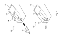
- a cell count measuring instrument 100 is provided with, as illustrated in FIGS. 1 and 2 , a measurement main body 10, and a cartridge 20 that is a liquid sample analyzing device detachably attached to the measurement main body 10.
- the measurement main body 10 is provided with: an attachment part 11 that is attached with the cartridge 20; a drive part 12 that slides a slide body 202 (to be described later) provided in the cartridge 20; a liquid supply part 13 for circulating diluted sample blood (hereinafter simply referred to as diluted blood), which serves as liquid to be measured, inside the cartridge 20; a connector part 14 for extracting a signal from the cartridge 20; and a calculation part 15 that detects the electrical signal from the connecter part 14 to calculate a cell count contained in the liquid to be measured.
- diluted blood circulating diluted sample blood
- the attachment part 11 is formed to be slightly larger than a width and thickness of a fore end corresponding to an insertion side end part of the cartridge 20, and provided with: a groove-like concave portion 11a (see FIG. 1 ) that is configured to have a predetermined depth so as to meet a shape of the insertion side end part of the cartridge 20; and a cover body 11b (see FIG. 2 ) that, when the cartridge 20 is inserted into the concave portion 11a, covers most of the cartridge 20 except a part (including a blood quantity determination part 22) for gripping the cartridge 20. Also, in a deep part of the concave portion 11a, a projection part 16 that is to fit into a cutout part 21 (see FIGS.
- the drive part 12 is configured to use: an engaging pawl that is to engage with a locking part 202a (specifically, a locking hole, see FIG. 4 ) provided in the slide body 202 of the cartridge 20; and a slide moving mechanism using a rack-and-pinion mechanism, motor, and the like that moves the engaging pawl in a slide direction (both not illustrated). Also, the drive part 12 is one that, in order to quantify blood, slides the slide body 202 between a blood quantity determination position X (see FIG. 5 ) and a blood introduction position Y (see FIG. 6 ) for mixing quantified blood with a reagent to introduce them into a mixing flow path 25 and a measuring flow path 26.
- a blood quantity determination position X see FIG. 5
- a blood introduction position Y see FIG. 6
- the liquid supply part 13 mainly includes a suction pump and a valve.
- the suction pump is one that is, when the cartridge 20 is attached to the attachment part 11, connected to an end point opening part H of the measuring flow path 26 to be described later; depressurizes the opening part H; and sucks and introduces the quantified blood and reagent into the mixing flow path 25 and measuring flow path 26 from a flow path inlet 24.
- the connector part 14 is provided with the conduction part 14a that is electrically conducted to an inside of the concave portion 11a of the attachment part 11, and one that, when the cartridge is attached, comes into contact with the electrode 28 of the cartridge 20 to apply a predetermined voltage to the electrode 28, and detects, as the electrical signal, a current amount proportional to an electrical resistance generated at the time of the application. Then, the connector part 14 outputs the electrical signal to the calculation part 15 through a wiring line such as a lead.
- the calculation part 15 is provided with an electrical circuit (not illustrated) that converts the electrical signal outputted from the connector part 14 to a pulse signal to output it as a blood cell count and blood cell volume value in the diluted blood introduced into the measuring flow path 26. Then, the signal regarding the blood cell count and blood cell volume outputted in the above manner is outputted to a display 101 or the like.
- the cartridge 20 is essentially a one-time disposable one, and provided with: the cutout part 21 having substantially a rectangular cross-sectional shape on the fore end side in an insertion direction thereof; and also near substantially the center of an end part on a side opposite to the fore end side in the insertion direction, the blood quantity determination part 22 having a blood inlet 22a that is opened on a surface of the blood quantity determination part 22.
- the cartridge 20 is provided with: a reagent container attachment part 23 that is attached with a reagent container 3 for diluting blood quantified by the blood quantity determination part 22; the flow path inlet 24 that introduces the quantified blood and reagent; the mixing flow path 25 that is formed with being communicatively connected to the flow path inlet 24; and the measuring flow path 26 for calculating the blood count contained in the diluted blood that is formed by the mixing through the mixing flow path 25.
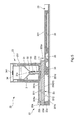
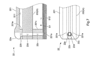
- the blood quantity determination part 22 includes: a cartridge main body 201 having an upstream side capillary flow path 22b that is formed in series with the blood inlet 22a and a downstream side capillary flow path 22c that is formed with sandwiching a space S1 (space forming a slide path for the after-mentioned slide body 202) with the upstream side capillary flow path 22b; and the slide body 202 that is slidably provided in the space S1, communicatively connects the upstream side capillary flow path 22b and the downstream side capillary flow path 22c to each other, and is formed with a quantity determining capillary flow path 22d that quantifies blood introduced from the blood inlet 22a and has a predetermined flow path volume.
- the engaging pawl of the drive part 12 engages with the locking part 202a formed on the insertion direction side, and by the drive part 12, the slide body 202 slides between the blood quantity determination position X ( FIG. 5 ) where the quantity determining capillary flow path 22d is communicatively connected to the upstream side capillary flow path 22b and the downstream side capillary flow path 22c and the blood introduction position Y ( FIG. 6 ) for introducing the blood quantified by the quantity determining capillary flow path 22d and the reagent into the flow path inlet 24.
- the upstream side capillary flow path 22b, the downstream side capillary flow path 22c, and the quantity determining capillary flow path 22d are linear flow paths respectively having constant cross-sectional circular shapes, and formed so as to face in the same direction (in the present embodiment, a vertical direction orthogonal to the insertion direction). Also, the upstream side capillary flow path 22b, quantity determining capillary flow path 22d, and downstream side capillary flow path 22c are reduced in diameter in this order.
- the quantity determining capillary flow path 22d is configured to be smaller in diameter than the upstream side capillary flow path 22b, and the downstream side capillary flow path 22c is configured to be smaller in diameter than the quantity determining capillary flow path 22d. This enables capillary force to be enhanced toward the downstream side, and blood to be surely introduced into the quantity determining capillary flow path 22d.
- the upstream side of the upstream side capillary flow path 22b is of a funnel shape that increases in diameter toward the upstream side, and the blood inlet 22a corresponding to an opening on the upstream side of the funnel shape is configured to be long-hole shaped, and formed in a corner part of the cartridge main body 201 to open on upper and side surfaces of the cartridge main body 201. This makes it easy to introduce blood from the blood inlet 22a.
- the upstream side capillary flow path 22b and the downstream side capillary flow path 22c are formed concentrically in a plan view, and a downstream side opening of the upstream side capillary flow path 22b is opened to the space S1 (slide path), and an upstream side opening of the downstream side capillary flow path 22c is opened to the space S1 (slide path).
- an upstream side opening of the quantity determining capillary flow path 22d is contained in the downstream side opening of the upstream side capillary flow path 22b, and the upstream side opening of the downstream side capillary flow path 22c is contained in a downstream side opening of the quantity determining capillary flow path 22d.
- the quantity determining capillary flow path 22d is positioned concentrically with respect to the upstream side capillary flow path 22b and the downstream side capillary flow path 22c.
- a liquid sensor 221 for detecting whether or not blood has reached is provided on a downstream side of the downstream side capillary flow path 22c.
- the liquid sensor 221 is configured to have electrodes, and includes: a liquid contact part 221a that is provided so as to block all or a part of a downstream side opening of the downstream side capillary flow path 22c; a lead 221b that is drawn from the liquid contact part 221a; and a signal extraction part 221c that is exposed on a cartridge surface below the cutout part 21 so as to be electrically conducted to the liquid contact part 221a through the lead 221b.
- a blood reduction preventing structure that, in the process of sliding the slide body 202 between the blood quantity determination position X and the blood introduction position Y, prevents a phenomenon in which an inner wall surface of the slide path S1 comes into contact with the upper and lower openings of the quantity determining capillary flow path 22d, and quantified blood adheres to the inner wall surface and is thereby reduced in quantity.
- the blood reduction preventing structure is, as illustrated in FIGS. 5 and 6 , and other drawings, provided with: an upper gap S11 that is provided between an forming wall part 201a forming the upstream side capillary flow path 22b and a forming wall part 201b forming a reagent introduction path L1; and a lower gap S12 that is provided between a forming wall part 201c forming the downstream side capillary flow path 22c and a forming wall part 201d forming the flow path inlet 24.
- the upstream side opening of the quantity determining capillary flow path 22d is configured not to come into contact with an upper wall surface of the cartridge main body 201.
- the downstream side opening of the quantity determining capillary flow path 22d is configured not to come into contact with a lower wall surface of the cartridge main body 201.
- the reagent container attachment part 23 is one that is detachably attached with the reagent container 3 serving as a liquid container for analysis, and as illustrated in FIGS. 5 and 6 , provided with: a container storage part 231 that is provided on an upper surface of the cartridge main body 201 and stores the reagent container 3; and a reagent lead-out needle 232 that is provided so as to extend from a bottom wall of the container storage part 231 and passes through a seal part 32 of the reagent container 3 stored in the container storage part 231.
- the reagent lead-out needle 232 is communicatively connected to the reagent introduction path L1 of which an internal flow path is opened to the space S1.
- the reagent container 3 is one that contains the reagent serving as a predetermined quantity of liquid for analysis, and as illustrated in FIG. 5 , provided with: a container main body 31 of which a bottom wall is formed with an opening part 31a that enables the reagent to be led out; the seal part 32 that seals the opening part 31a;and a guide part 33 that is provided outside the seal part 32 and substantially cylindrically shaped.
- the container main body 31 is substantially rotating body shaped, and the bottom wall is funnel shaped. Also, the opening part 31a is formed in substantially the center of the bottom wall. Further, the guide part 33 is provided so as to cover a circumference of the seal part 32, and one that serves as a guide for inserting the reagent lead-out needle 232 into the seal part 32 and when the reagent lead-out needle 232 is inserted into the seal part 32, substantially liquid-tightly comes into contact with an outer circumferential surface of the reagent lead-out needle 232.
- the reagent container 3 of the present embodiment is made of resin such as polypropylene, and the container main body 31, the seal part 32, and the guide part 33 are formed by integral molding.
- An upper part of the reagent container 3 is opened, and after the reagent has been contained from the opening, sealed by a sealing film 34 such as an aluminum film.
- the sealing film 34 is provided with an atmospheric opening part 341 including, for example, a resin check valve, and simultaneously with or before the insertion of the reagent lead-out needle 232 into the seal part 32, an unillustrated ventilation needle is inserted to open the reagent container 3 to the atmosphere.
- the guide part 33 substantially liquid-tightly comes into close contact with the outer circumferential surface of the reagent lead-out needle 232 before the reagent lead-out needle 232 is inserted into the seal part 32.
- the reagent lead-out needle 232 is gradually increased in diameter from a fore end toward a base end, and the guide part 33 is configured such that as the reagent lead-out needle 232 is inserted into the guide part 33, a fore end of the guide part 33 comes into close contact with and engages with the outer circumferential surface of the reagent lead-out needle 232 with deforming, and thereby the guide part 33 liquid-tightly comes into contact with the outer circumferential surface of the reagent lead-out needle 232 (see FIG. 6 ).
- an inside diameter of the guide part 33 is formed to be slightly smaller than an outside diameter of the base end of the reagent lead-out needle 232.
- an axial length of the guide part 33 is a length enough to, before the reagent lead-out needle 232 is inserted into the seal part 32, substantially liquid-tightly bring an inner circumferential surface of the guide part 33 into contact with the whole of the outer circumferential surface of the reagent lead-out needle 232 in a circumferential direction.
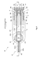
- the mixing flow path 25 is, as illustrated in FIGS. 3 and 4 , formed in series with the flow path inlet 24 opened to the slide path S1, and also formed so as to meander inside the cartridge main body 201.
- the sample inlet 24 is, in the state where the slide body 202 is at the blood introduction position Y, communicatively connected to the downstream side opening of the quantity determining capillary flow path 22d (see FIG. 6 ).
- the reagent is introduced together with blood inside the quantity determining capillary flow path 22d into the mixing flow path 25 through the quantity determining capillary flow path 22d from the reagent introduction path L1 communicatively connected to the reagent lead-out needle 232 inserted into the reagent container 3. Then, by the suction/discharge operation of the pump of the liquid supply part 13, the quantified blood and reagent are mixed in the mixing flow path 25 to form diluted blood.
- the measuring flow path 26 serving as a liquid sample flow path is, as illustrated in FIGS. 3 and 4 , formed so as to be communicatively connected to a downstream side outlet of the mixing flow path 25, and configured to linearly extend from the downstream side outlet toward the fore end side so as to halve the whole of the cartridge main body 201.
- the measuring flow path 26 is narrowed such that inner walls facing to each other in the flow path 26 form a gap of approximately 1 mm near the cutout part 21 on the fore end side, and by the gap, an aperture part 27 is formed. Note that a size of the gap for forming the aperture part 27 can be appropriately set depending on a size of a cell to be measured (in the present embodiment, a blood cell).
- the measuring flow path 26 is, in particular as illustrated in FIG. 8 , divided into two branches toward the downstream side from the position where the aperture part 27 is formed.
- the flow path 26a on the upstream side of the aperture part 27 is configured so as to gradually narrow a distance between the inner walls facing to each other toward the aperture part 27, and each of the flow paths 26b and 26c on the downstream side is configured so as to gradually expand a distance between inner walls facing to each other from the aperture part 27.
- a flow path width is almost constant.
- each of the columnar parts F1 is of a cylindrical shape having a diameter of 0.3 mm, and in a direction in which the columnar parts F1 block the flow path (in a direction orthogonal to the flow path direction), the columnar parts F1 are linearly arranged at the intervals of, for example, 30 to 60 ⁇ m, preferably 50 ⁇ m.
- the columnar parts F1 are arranged in two lines to form the filter part F; enable the red blood cells (cell diameter of approximately 8 ⁇ m), white blood cells (cell diameter of approximately 10 to 20 ⁇ m), platelets (cell diameter of approximately 2 to 3 ⁇ m) and the like to pass through the filter part F; and stop foreign substances such as dust and dirt each having a diameter of 50 ⁇ m or more at the filter part F. This prevents the foreign substances from reaching the electrodes 28 and 29, and therefore measurement accuracy of the blood analysis can be improved.
- each of the flow paths 26b and 26c is slightly formed linearly from the branch position along a fore end side of the cartridge main body 201; then bends and linearly extends toward a rear end of the cartridge; and again extends from the rear end to the fore end. By repeating this multiple times, each of the flow paths 26b and 26c is formed zigzag (see FIG. 4 ).
- the measuring flow path 26 is configured to bend multiple times at the end part side with respect to the insertion direction of the cartridge main body 201, and formed over substantially the whole area of the cartridge main body 201. This allows the measuring flow path 26 to be ensured as long as possible within a limited area inside the cartridge main body 201.
- the measuring flow path 26 is configured such that final end parts thereof are communicatively connected to opening parts H opened on a surface (lower surface) of the cartridge main body 201, and the diluted blood introduced from the flow path inlet 24 travels in the measuring flow path 26 so as to push out air contained in the measuring flow path 26 from the opening parts H.
- each of the electrodes 28 includes: a liquid contact part 28a that is formed so as to face to the inner wall of the measuring flow path 26; a lead 28b that is drawn from the liquid contact part 28a; and a signal extraction part 28c that is exposed on the cartridge surface on the cutout part 21 so as to be electrically conducted to the liquid contact part 28a through the lead 28b.
- the second electrode 29 includes: a liquid detection part 29 that is provided on a downstream side where a flow path volume from the liquid contact part 28a becomes equal to a predetermined constant volume (specifically, on an upstream side from the end point of the measuring flow path 26 by a predetermined distance); a lead 29b that is drawn from the liquid detection part 29a; and a detected signal output part 29c that is in series with an end point of the lead 29b and provided laterally to the signal extraction part 28c, and acts as a liquid level sensor adapted to detect that the diluted blood has reached the liquid detection part 29a.
- the liquid supply part 13 stops supplying the diluted blood, and thereby the diluted blood can be prevented from reaching the opening part H at the end point of the flow path to overflow.
- the signal extraction part 28c of the first electrode 28 and the detected signal output part 29c of the second electrode 29 are, as described above, arranged side by side, and configured to, when the cartridge 20 is attached to the measurement main body 10, come into electrical contact with the conduction part 14a of the connector part 14.
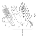
- the cartridge main body 201 includes, as illustrated in FIG. 10 , a base material 40 that has a surface formed with bottom-equipped grooves 41 and 42 and is made of, for example, PMMA, and a film 60 that is stuck on the surface (lower surface) of the base material 40 through an adhesive sheet 50 and serves as a cover member made of PET.
- the first bottom-equipped groove 41 is a semicircular groove that is opened on the base material surface (lower surface) and has a width of approximately 4 mm and a depth of approximately 2 mm
- the second bottom-equipped groove 42 is a concave groove that is opened on the base material surface (lower surface) and has a width of approximately 1 mm and a depth of approximately 1 mm.
- a start point of the first bottom-equipped groove 41 is provided with the flow path inlet 24.
- the sample introduction path L1 and the reagent container attachment part 23 are formed respectively inside the base material and on a base material surface (upper surface on a side opposite to the surface formed with the grooves).
- a start point of the second bottom-equipped groove 42 is in series with an end point of the first bottom-equipped groove 41. Further, as described above, near the upstream side of the position where the aperture part 27 is formed, the width of the second bottom-equipped groove 42 is gradually narrowed, and near the downstream side of the position where the aperture part 27 is formed, the width of the second bottom-equipped groove is gradually expanded.
- Such bottom-equipped groove 42 and columnar parts F1 of the filter part F may be formed by any fabrication method such as micromachining fabrication, hot emboss fabrication, or optical molding, or in the case of forming the base material 40 with resin, by a method such as precision injection molding, molding may be performed so as to form a shape preliminarily having such grooves.
- the film 60 is formed to have a shape that substantially coincide with the shape of the base material surface, and when stuck on the base material surface, covers opening parts of the bottom-equipped grooves 41 and 42 to thereby form the mixing flow path 25 and the measuring flow path 26, and at the positions corresponding to end points of the second bottom equipped groove 42, through-holes 61a and 61b are formed. Also, the film 60 is not provided with a cutout in a position corresponding to the cutout part 21 of the base material 40, and configured such that when the base material 40 and the film 60 are bonded to each other, a part of the film 60 covers an upside of the cutout part 21.
- the signal extraction part 28c that is a part of the first electrode 28, the detected signal output part 29c that is a part of the second electrode 29, and the signal extraction part 221c that is a part of the liquid sensor 221 are formed.
- the above-described first and second electrodes 28 and 29 are formed.
- the liquid contact part 28a and the liquid detection part 29a respectively constituting the electrodes come into contact with the diluted blood flowing through the measuring flow path 26 to be thereby electrically conducted to each other, and are also electrically connected to the signal extraction part 28c and the detected signal output part 29c through the leads 28b and 29b, respectively.
- the liquid sensor 221 is formed in the same manner.
- the first and second electrodes 28 and 29 formed on the surface 601 of the film 60 are formed by a method such as screen printing or sputtering. It should be appreciated that these electrodes can also be formed by a method other than the above-described ones, and even in the case of using a method that deposits a layer of a mixed material of silver and carbon on the whole of a back surface of the film 60, and removes or metamorphoses silver in unnecessary parts by etching or electrical treatment, these electrodes can be formed. In this case, as compared with the above-described electrodes formed by the screen printing or sputtering, the electrodes having a smaller film thickness can be formed. In addition, the liquid sensor 221 is formed in the same manner.
- the adhesive sheet 50 for bonding the base material 40 and the film 60 to each other is formed of a thin film like solid adhesive 50 that covers the whole of the surface of the base material 40 except for parts corresponding to the locations where the through-holes 61a and 61b, the liquid contact parts 28a, the liquid detection parts 29a, and the liquid contact parts 221a of the film 60 are formed.
- a reference numeral 51a represents through-holes corresponding to the through-holes 61a and 61b; 51b represents rectangular-shaped holes corresponding to the liquid contact parts 28a; 51c represents rectangular-shaped holes corresponding to the liquid detection parts 29a; and 51d represents a rectangular-shaped hole corresponding to the liquid contact parts 221a.
- the solid adhesive 50 is solid at room temperature; however, it has a property in which when it is heated to a predetermined temperature or more, it melts to give rise to adhesive property.
- the liquid contact parts 28a of the first electrodes 28 and the liquid detection parts 29a of the second electrodes that are provided on the surface 601 corresponding to an adhesion surface of the film 60 are, as illustrated in FIG. 11 , configured to be contained and arranged in a stepwise concave portion 7 formed by the adhesive sheet 50 and the adhesion surface 601 of the film 60.
- thicknesses of the electrodes (liquid contact parts 28a and liquid detection parts 29a) formed on the surface 601 of the film 60 are approximately 0.015 mm, and a thickness of the adhesive sheet 50 is approximately 0.1 mm, so that the electrodes (liquid contact parts 28a and liquid detection parts 29a) are completely contained in the stepwise concave portion 7.
- FIG. 11 illustrates an upside-down diagram.
- a projection part T is provided at a position facing to the stepwise concave portion 7.
- the projection part T is one that generates a turbulent flow in the flow of the diluted blood when the diluted blood circulates on a front side of the opening of the stepwise concave portion 7.
- the projection part T is formed on an inner wall surface 262 (in FIG. 11 , lower surface) facing to an inner wall surface 261 (in FIG. 11 , upper surface) formed with the stepwise concave portion 7 in the measuring flow path 26, and provided so as to face to the liquid contact part 28a of the first electrode 28 and the liquid detection part 29a of the second electrode 29.
- the projection part T is formed over the whole area in a flow path width direction, and has a constant cross-sectional shape in the flow path width direction.
- the projection part T is formed on a bottom surface of the bottom-equipped groove 42 of the base material 50 in the width direction.
- the projection part T of the present embodiment is one of which a cross-section along the flow path direction is substantially trapezoidally shaped.
- at least a downstream side edge T1 of a top surface of the projection part T is positioned on the front side of the opening of the stepwise concave portion 7, i.e., positioned within a flow path range the stepwise concave portion 7 faces to.
- a position of an upstream side edge of the top surface of the projection part T is not particularly limited; however, the present embodiment illustrates the case where the upstream side edge is positioned near a downside of an upstream side end of the stepwise concave portion 7.
- the reagent container 3 is stored in the reagent container attachment part 23 of the cartridge main body 201.
- the reagent lead-out needle 232 of the reagent container attachment part 23 is not yet inserted into the seal part 32.
- a position of the slide body 202 with respect to the cartridge main body 201 corresponds to the blood quantity determination position X.
- the cartridge 20 is attached to the measurement main body 10. If the cover body 11b is closed in this state, the ventilation needle provided for the cover body 11b is inserted into the atmospheric opening part 341 of the reagent container 3, and at the same time, the reagent container 3 is attached to the reagent container attachment part 23. That is, the reagent lead-out needle 232 is inserted into the seal part 32.
- the signal extraction parts 28c, detected signal output parts 29c, and signal extraction parts 221c formed on the surface of the cartridge main body 201 come into contact with the conduction part 14a of the connector part 14 to supply a small amount of a current so as to apply a predetermined voltage from the conduction part 14a to the liquid sensor 221, and first and second electrodes 28 and 29 of the cartridge main body 201.
- the measurement main body 10 obtains a detected signal from the liquid sensor 221 provided at the downstream side opening of the downstream side capillary flow path 22c to determine whether or not the blood has reached the downstream side capillary flow path 22c.
- the measurement main body 10 determines that the blood has reached the downstream side capillary flow path 22c
- the measurement main body 10 slides the slide body 202 from the blood quantity determination position X to the blood introduction position Y.
- blood outside the quantity determining capillary flow path 22d is struck by the forming wall part forming the upstream side capillary flow path 22b and the forming wall part forming the downstream side capillary flow path 22c, and only the blood retained in the quantity determining capillary flow path 22d moves to the blood introduction position Y.
- the liquid supply part 13 After the slide body 202 has been moved to the blood introduction position Y, the liquid supply part 13 operates to depressurize the flow path inlet 24, and thereby the blood inside the quantity determining capillary flow path 22d and the reagent are sucked into the mixing flow path 25. Then, the liquid supply part 13 performs the suction/discharge operation of the pump to thereby mix the blood and the reagent in the mixing flow path 25 and/or the reagent container 3. After the mixing, by the liquid supply part 13, the diluted blood is sucked into the measuring flow path 26.
- the connector part 14 detects an electrical resistance value between the liquid contact parts 28a as an electrical signal through the signal extraction parts 28c.
- the electrical signal is a pulse signal proportional to the electrical resistance value that is varied on the basis of a blood cell count and volume (diameter) in the diluted blood passing through the aperture part 27, and the connector part 14 calculates, from the electrical signal, the blood cell count and volume in the diluted blood having passed through the aperture part 27 for a predetermined period of time (for example, a period of time from a time point when the diluted blood reaches the liquid contact parts 28a of the first electrodes 28 to a time point when it reaches the liquid detection parts 29 of the second electrodes 29), and then outputs a result of the calculation to the display 101, or the like.
- a predetermined period of time for example, a period of time from a time point when the diluted blood reaches the liquid contact parts 28a of the first electrodes 28 to a time point when it reaches the liquid detection parts 29 of the second electrodes 29
- the diluted blood supplied into the measuring flow path 26 passes through the positions where the first electrode liquid contact parts 28a and 28a are provided, and further reaches the positions where the second electrode liquid detection parts 29a and 29a are provided, an electrical resistance value between the first electrodes 28 is detected as an electrical signal through the detected signal output parts 29c and 28c.
- the electrical signal is detected in the connector part 14, the calculation is stopped, and also a switching valve is operated to switch the opening parts H from the liquid supply part 13 and communicatively connect the opening parts H to the atmosphere. This returns the opening parts H to the atmospheric pressure to stop the suction of the diluted blood.
- the cartridge 20 When the measurement of the blood cell count in the diluted blood is completed as described, the cartridge 20 is detached from the attachment part 11, and the cartridge 20 containing the diluted blood is discarded according to a predetermined process such as incineration.
- the cell count measuring instrument 100 configured in the above-mentioned manner of the present embodiment, in the structure where the electrodes 28a and 29a are arranged in the stepwise concave portion formed on the inner wall surface of the measuring flow path 26 that is the liquid sample flow path, since the projection part T is provided at a front of the opening of the stepwise concave portion to generate the turbulent flow, the diluted blood flows toward the electrodes 28a and 29a side due to the turbulent flow, and thus it is possible to remove the air bubbles attached to the electrodes 28a and 29a and to prevent the air bubbles from being generated in the vicinity of the electrodes 28a and 29a.
- the measuring flow path 26 is narrowed by the projection part T, and thus the flow velocity of diluted blood is increased, it accordingly becomes possible to make the attachment of the air bubbles hard and to enhance the turbulent flow in the lower current than the projection part T, which makes the diluted blood easy to flow toward the electrodes 28a and 29a side.
- the projection part is substantially trapezoidally shaped in a cross-section along the flow path direction; however, in addition, the cross-section may be in a semicircular shape, in a triangular shape, and in a rectangular shape.
- the projection parts are formed over along a direction of the flow path width on the inner wall surface facing the electrode, and the cross section along the flow path direction is shaped so as to have a uniform section; however, in addition, the projection parts may be partially formed on the inner wall surface facing the electrode and may be not shaped so as to have a uniform section.
- the wall surface on which the projection part is provided is not limited to the inner wall surface facing the electrode when arranged at a position facing to the stepwise concave portion in which the electrode is formed, and in a case where the measuring flow path has a cross section substantially formed in a rectangular shape, the projection part may be provided on an inner wall surface perpendicular to the inner wall surface facing the electrode.
- the upstream side capillary flow path, the downstream side capillary flow path, and the quantity determining capillary flow path are linear flow paths shaped so as to have a uniform section, respectively, and additionally, in the flow paths at the blood quantity determination position, when an upstream side opening of the downstream side capillary flow path is included in a downstream side opening of the upstream side capillary flow path and when an upstream side opening of the quantity determining capillary flow path is included in a downstream side opening of the quantity determining capillary flow path, the upstream side capillary flow path, the downstream side capillary flow path, and the quantity determining capillary flow path may be a curved flow path and may be inclined in a perpendicular direction or in a horizontal direction.
- the mixing flow path and the measuring flow path circulate the blood, the reagent, and the diluted blood due to the suction operation of the pump; however, in addition, the flow paths may circulate the blood, the reagent, and the diluted blood due to the capillarity.
- the cartridge whose flow path is branched at the aperture part is disclosed; however, the present invention is not limited to the embodiments, and may form the aperture in a general single flow path and arrange the electrodes at an upstream and a downstream sandwiching the aperture part.
- the timing at which the supply of liquid to be measured into the flow path is stopped is determined in the manner where the second electrode provided in the flow path detects the liquid to be measured; however, if a length and the like of the flow path formed in the cartridge is designed to be known, a supply amount of the liquid to be measured into the flow path may be preliminarily determined. In this case, a possibility that the liquid to be measured overflows from the opening can be eliminated without carrying out a particular detection.
Landscapes
- Chemical & Material Sciences (AREA)
- Health & Medical Sciences (AREA)
- Analytical Chemistry (AREA)
- General Health & Medical Sciences (AREA)
- Immunology (AREA)
- Biochemistry (AREA)
- Life Sciences & Earth Sciences (AREA)
- General Physics & Mathematics (AREA)
- Physics & Mathematics (AREA)
- Pathology (AREA)
- Dispersion Chemistry (AREA)
- Hematology (AREA)
- Clinical Laboratory Science (AREA)
- Chemical Kinetics & Catalysis (AREA)
- Automatic Analysis And Handling Materials Therefor (AREA)
- Investigating Or Analysing Biological Materials (AREA)
Applications Claiming Priority (1)
| Application Number | Priority Date | Filing Date | Title |
|---|---|---|---|
| JP2010025941A JP5433453B2 (ja) | 2010-02-08 | 2010-02-08 | 液体試料分析機器 |
Publications (1)
| Publication Number | Publication Date |
|---|---|
| EP2353718A2 true EP2353718A2 (de) | 2011-08-10 |
Family
ID=44064913
Family Applications (1)
| Application Number | Title | Priority Date | Filing Date |
|---|---|---|---|
| EP11000876A Withdrawn EP2353718A2 (de) | 2010-02-08 | 2011-02-03 | Flüssigprobenanalysegerät |
Country Status (3)
| Country | Link |
|---|---|
| US (1) | US8490502B2 (de) |
| EP (1) | EP2353718A2 (de) |
| JP (1) | JP5433453B2 (de) |
Cited By (4)
| Publication number | Priority date | Publication date | Assignee | Title |
|---|---|---|---|---|
| WO2012092593A1 (en) * | 2010-12-30 | 2012-07-05 | Abbott Point Of Care, Inc. | Biologic fluid analysis cartridge with sample handling portion and analysis chamber portion |
| CN103105487A (zh) * | 2011-11-10 | 2013-05-15 | 五鼎生物技术股份有限公司 | 反应卡匣及检测装置 |
| EP2881743A4 (de) * | 2012-07-31 | 2015-08-05 | I Sens Inc | Biochemische analysenkassette mit verbesserter bedienbarkeit |
| US20230094429A1 (en) * | 2021-09-30 | 2023-03-30 | Enplas Corporation | Cartridge and liquid handling device |
Families Citing this family (16)
| Publication number | Priority date | Publication date | Assignee | Title |
|---|---|---|---|---|
| CN102762289B (zh) | 2009-12-18 | 2016-08-03 | 艾博特健康公司 | 生物流体分析卡盒 |
| US9199233B2 (en) | 2010-03-31 | 2015-12-01 | Abbott Point Of Care, Inc. | Biologic fluid analysis cartridge with deflecting top panel |
| JP5432862B2 (ja) * | 2010-08-23 | 2014-03-05 | 株式会社堀場製作所 | 体液分析器具 |
| KR101275742B1 (ko) * | 2011-06-23 | 2013-06-17 | 주식회사 아이센스 | 광학 분석용 셀 |
| CN103890590B (zh) | 2011-08-24 | 2016-03-09 | 艾博特健康公司 | 生物流体样品分析盒 |
| JP2013150567A (ja) * | 2012-01-25 | 2013-08-08 | Hitachi High-Technologies Corp | 核酸分析用反応デバイス、及び核酸分析装置 |
| US9075042B2 (en) | 2012-05-15 | 2015-07-07 | Wellstat Diagnostics, Llc | Diagnostic systems and cartridges |
| US9625465B2 (en) | 2012-05-15 | 2017-04-18 | Defined Diagnostics, Llc | Clinical diagnostic systems |
| US9213043B2 (en) | 2012-05-15 | 2015-12-15 | Wellstat Diagnostics, Llc | Clinical diagnostic system including instrument and cartridge |
| HU230238B1 (hu) * | 2013-02-05 | 2015-10-28 | NORMA Instruments Zártkörűen Működő Részvénytársaság | Mérőegység folyadékot tartalmazó minták fizikai jellemzőinek meghatározásához |
| US10369567B2 (en) * | 2015-11-04 | 2019-08-06 | International Business Machines Corporation | Continuous, capacitance-based monitoring of liquid flows in a microfluidic device |
| CN110869746B (zh) | 2017-08-17 | 2023-08-11 | 雅培医护站股份有限公司 | 利用通用电路系统执行光学和电化学测定的技术 |
| US11253852B2 (en) | 2017-08-17 | 2022-02-22 | Abbott Point Of Care Inc. | Devices, systems, and methods for performing optical assays |
| US11067526B2 (en) | 2017-08-17 | 2021-07-20 | Abbott Point Of Care Inc. | Devices, systems, and methods for performing optical and electrochemical assays |
| CN107715932B (zh) * | 2017-11-23 | 2023-06-16 | 昌微系统科技(上海)有限公司 | 一种微流体器件 |
| US12590896B2 (en) | 2019-05-28 | 2026-03-31 | Robert A. Levine | Apparatus and method for transferring and analyzing suspended particles in a liquid sample |
Citations (1)
| Publication number | Priority date | Publication date | Assignee | Title |
|---|---|---|---|---|
| JP2007017302A (ja) | 2005-07-07 | 2007-01-25 | Horiba Ltd | 粒子数計測装置 |
Family Cites Families (5)
| Publication number | Priority date | Publication date | Assignee | Title |
|---|---|---|---|---|
| JP3778041B2 (ja) * | 2000-12-08 | 2006-05-24 | コニカミノルタホールディングス株式会社 | 粒子分離機構及び粒子分離装置 |
| JP4613099B2 (ja) * | 2005-06-03 | 2011-01-12 | シャープ株式会社 | 電気化学検出装置 |
| US7463158B2 (en) * | 2005-10-19 | 2008-12-09 | Linear Measurements, Inc. | Acoustic particle alarm including particle sensor |
| US7793554B2 (en) * | 2009-02-05 | 2010-09-14 | Masco Corporation | Flexible sensor flow and temperature detector |
| US8941062B2 (en) * | 2010-11-16 | 2015-01-27 | 1087 Systems, Inc. | System for identifying and sorting living cells |
-
2010
- 2010-02-08 JP JP2010025941A patent/JP5433453B2/ja not_active Expired - Fee Related
-
2011
- 2011-02-03 EP EP11000876A patent/EP2353718A2/de not_active Withdrawn
- 2011-02-08 US US13/023,149 patent/US8490502B2/en not_active Expired - Fee Related
Patent Citations (1)
| Publication number | Priority date | Publication date | Assignee | Title |
|---|---|---|---|---|
| JP2007017302A (ja) | 2005-07-07 | 2007-01-25 | Horiba Ltd | 粒子数計測装置 |
Cited By (5)
| Publication number | Priority date | Publication date | Assignee | Title |
|---|---|---|---|---|
| WO2012092593A1 (en) * | 2010-12-30 | 2012-07-05 | Abbott Point Of Care, Inc. | Biologic fluid analysis cartridge with sample handling portion and analysis chamber portion |
| CN103105487A (zh) * | 2011-11-10 | 2013-05-15 | 五鼎生物技术股份有限公司 | 反应卡匣及检测装置 |
| EP2881743A4 (de) * | 2012-07-31 | 2015-08-05 | I Sens Inc | Biochemische analysenkassette mit verbesserter bedienbarkeit |
| US9316655B2 (en) | 2012-07-31 | 2016-04-19 | I-Sens, Inc. | Biochemical analysis cartridge having improved operability |
| US20230094429A1 (en) * | 2021-09-30 | 2023-03-30 | Enplas Corporation | Cartridge and liquid handling device |
Also Published As
| Publication number | Publication date |
|---|---|
| US20110192219A1 (en) | 2011-08-11 |
| US8490502B2 (en) | 2013-07-23 |
| JP2011163881A (ja) | 2011-08-25 |
| JP5433453B2 (ja) | 2014-03-05 |
Similar Documents
| Publication | Publication Date | Title |
|---|---|---|
| EP2353718A2 (de) | Flüssigprobenanalysegerät | |
| JP5506440B2 (ja) | 液体試料定量器 | |
| US20110194977A1 (en) | Liquid container for analysis | |
| US8354059B2 (en) | Cell analysis cartridge | |
| JP5579537B2 (ja) | 細胞分析用カートリッジ | |
| US10369567B2 (en) | Continuous, capacitance-based monitoring of liquid flows in a microfluidic device | |
| US8501112B2 (en) | Body fluid analysis fixture | |
| US11161114B2 (en) | Ph control for analyte detection | |
| CN107567582B (zh) | 用于流体测试单元的光引导件 | |
| CN103558126B (zh) | 测定与分析液体中粒子的装置及方法 | |
| CN101297200A (zh) | 送液方法及其所使用的液盒 | |
| JP2007064742A (ja) | 化学チップおよび接続装置 | |
| CN108495713B (zh) | 包括集成电极的微流体流动池及其制造方法 | |
| EP2957343A1 (de) | Fluidhandhabungsvorrichtung | |
| CN114008462A (zh) | 试剂容器和使用方法 | |
| JP2012042424A (ja) | 体液分析器具 | |
| CN114994157A (zh) | 用于分析液体样品的装置 | |
| JP4567540B2 (ja) | 細胞数計測装置および細胞数計測用カートリッジ | |
| KR101894100B1 (ko) | 바이오 센서 | |
| US10549480B2 (en) | Ultrasonic welding of a microfluidic device | |
| WO2009024916A1 (en) | Vent design for biosensor cartridge | |
| JP4824667B2 (ja) | 被検液分析用チップ | |
| JP6049463B2 (ja) | マイクロチップ | |
| US9283558B2 (en) | Fluid handling device | |
| JP2006234499A (ja) | マイクロチップ検査装置 |
Legal Events
| Date | Code | Title | Description |
|---|---|---|---|
| PUAI | Public reference made under article 153(3) epc to a published international application that has entered the european phase |
Free format text: ORIGINAL CODE: 0009012 |
|
| AK | Designated contracting states |
Kind code of ref document: A2 Designated state(s): AL AT BE BG CH CY CZ DE DK EE ES FI FR GB GR HR HU IE IS IT LI LT LU LV MC MK MT NL NO PL PT RO RS SE SI SK SM TR |
|
| AX | Request for extension of the european patent |
Extension state: BA ME |
|
| STAA | Information on the status of an ep patent application or granted ep patent |
Free format text: STATUS: THE APPLICATION HAS BEEN WITHDRAWN |
|
| 18W | Application withdrawn |
Effective date: 20150107 |