EP2353143B1 - Procédé et système de contrôle pour réaliser un contrôle optique d'un objet - Google Patents
Procédé et système de contrôle pour réaliser un contrôle optique d'un objet Download PDFInfo
- Publication number
- EP2353143B1 EP2353143B1 EP09778669.3A EP09778669A EP2353143B1 EP 2353143 B1 EP2353143 B1 EP 2353143B1 EP 09778669 A EP09778669 A EP 09778669A EP 2353143 B1 EP2353143 B1 EP 2353143B1
- Authority
- EP
- European Patent Office
- Prior art keywords
- test
- segment
- contour
- cells
- along
- Prior art date
- Legal status (The legal status is an assumption and is not a legal conclusion. Google has not performed a legal analysis and makes no representation as to the accuracy of the status listed.)
- Active
Links
- 238000012360 testing method Methods 0.000 title claims description 731
- 238000000034 method Methods 0.000 title claims description 89
- 230000015654 memory Effects 0.000 claims description 22
- 238000004590 computer program Methods 0.000 claims description 2
- 238000010998 test method Methods 0.000 description 10
- 230000007704 transition Effects 0.000 description 9
- 238000001514 detection method Methods 0.000 description 7
- 230000003287 optical effect Effects 0.000 description 7
- 238000007689 inspection Methods 0.000 description 6
- 230000008569 process Effects 0.000 description 6
- 230000006978 adaptation Effects 0.000 description 4
- 230000008901 benefit Effects 0.000 description 4
- 238000012545 processing Methods 0.000 description 4
- 230000001154 acute effect Effects 0.000 description 3
- 238000007781 pre-processing Methods 0.000 description 3
- 238000003860 storage Methods 0.000 description 3
- 238000004458 analytical method Methods 0.000 description 2
- 238000010276 construction Methods 0.000 description 2
- 230000001419 dependent effect Effects 0.000 description 2
- 238000011161 development Methods 0.000 description 2
- 230000018109 developmental process Effects 0.000 description 2
- 238000010586 diagram Methods 0.000 description 2
- 238000000605 extraction Methods 0.000 description 2
- 238000004519 manufacturing process Methods 0.000 description 2
- 238000005259 measurement Methods 0.000 description 2
- 230000000877 morphologic effect Effects 0.000 description 2
- 230000035945 sensitivity Effects 0.000 description 2
- 238000013459 approach Methods 0.000 description 1
- 230000015572 biosynthetic process Effects 0.000 description 1
- 230000008859 change Effects 0.000 description 1
- 239000007795 chemical reaction product Substances 0.000 description 1
- 150000001875 compounds Chemical class 0.000 description 1
- 230000007423 decrease Effects 0.000 description 1
- 230000010339 dilation Effects 0.000 description 1
- 230000003628 erosive effect Effects 0.000 description 1
- 238000011156 evaluation Methods 0.000 description 1
- 238000012854 evaluation process Methods 0.000 description 1
- 239000012530 fluid Substances 0.000 description 1
- 238000009499 grossing Methods 0.000 description 1
- 230000006872 improvement Effects 0.000 description 1
- 239000013067 intermediate product Substances 0.000 description 1
- 238000004382 potting Methods 0.000 description 1
- 238000003672 processing method Methods 0.000 description 1
- 238000009420 retrofitting Methods 0.000 description 1
- 230000011218 segmentation Effects 0.000 description 1
- 230000009466 transformation Effects 0.000 description 1
- 238000010200 validation analysis Methods 0.000 description 1
- 238000011179 visual inspection Methods 0.000 description 1
- 230000003936 working memory Effects 0.000 description 1
Images


Classifications
-
- G—PHYSICS
- G06—COMPUTING; CALCULATING OR COUNTING
- G06T—IMAGE DATA PROCESSING OR GENERATION, IN GENERAL
- G06T7/00—Image analysis
- G06T7/0002—Inspection of images, e.g. flaw detection
- G06T7/0004—Industrial image inspection
- G06T7/001—Industrial image inspection using an image reference approach
-
- G—PHYSICS
- G06—COMPUTING; CALCULATING OR COUNTING
- G06T—IMAGE DATA PROCESSING OR GENERATION, IN GENERAL
- G06T2207/00—Indexing scheme for image analysis or image enhancement
- G06T2207/20—Special algorithmic details
- G06T2207/20004—Adaptive image processing
- G06T2207/20012—Locally adaptive
-
- G—PHYSICS
- G06—COMPUTING; CALCULATING OR COUNTING
- G06T—IMAGE DATA PROCESSING OR GENERATION, IN GENERAL
- G06T2207/00—Indexing scheme for image analysis or image enhancement
- G06T2207/20—Special algorithmic details
- G06T2207/20021—Dividing image into blocks, subimages or windows
-
- G—PHYSICS
- G06—COMPUTING; CALCULATING OR COUNTING
- G06T—IMAGE DATA PROCESSING OR GENERATION, IN GENERAL
- G06T2207/00—Indexing scheme for image analysis or image enhancement
- G06T2207/30—Subject of image; Context of image processing
- G06T2207/30108—Industrial image inspection
- G06T2207/30164—Workpiece; Machine component
Definitions
- the invention relates to a method for the automatic optical examination of a contour of a test object by first acquiring a test pattern from a desired test area of a test object to be tested, defining a test section within the test pattern along the contour to be tested, and then for test cells defined along the test section which each comprise a number of pixels, test parameter values are determined. On the basis of the test parameter values of the test cells, deviations from predetermined reference values are finally detected in order to carry out the desired test.
- the invention further relates to a test system for carrying out such a method.
- FIG. 1 A test of an object along a test track is first schematically illustrated by the accompanying FIG. 1 clarified.
- FIG. 1 is shown as an example of a part of an object O whose outer edge has a certain contour K to be tested.
- Such a contour test is a common task in the context of automatic optical object inspection.
- test object For example, such inner or outer boundary edges of the test object or of parts of the test object or boundary lines between certain components or components of the test object are examined for errors.
- a typical example of this is the control of the tight completion of a potting compound in one Housing opening, for example in a relay or other electrical or electronic component.
- a method for optical inspection of a complete surface is described, for example, in US Pat WO 2008/077680 A1 described.
- a test is not carried out along a test track, but instead a virtual grid is placed over the image with the test object and the entire image is subdivided into a plurality of smaller image areas that cover a surface without overlapping.
- For each of these image areas in each case at least one reference and one test value are determined according to a test criterion, which are compared with one another to determine deviations.
- the grid is respectively aligned with reference points, reference numerals or reference lines, for example, a center line or a plurality of mutually perpendicular center lines of the respective object in the image.
- reference points, reference numerals or reference lines for example, a center line or a plurality of mutually perpendicular center lines of the respective object in the image.
- a test track in which the test is to take place along a test track, a test track must be laid over the test areas accordingly so that ultimately the entire test area is covered by test cells placed along the test track.
- the contour K of the test object O points approximately in the middle of the in FIG. 1 contour section shown an error in the form of a recess.
- the test along the specified test track PS takes place with the aid of rectangular test cells Z, which usually comprise a plurality of pixels or pixels.
- test cells Z usually comprise a plurality of pixels or pixels.
- a test cell structure with a series of such test cells Z is set.
- the operator can pre-set not only the test track PS itself, but also some other parameters for the test, such as the cell width ZW X of the cells Z in the scanning direction x or the height ZW Y the test cells Z perpendicular to the scanning direction x.
- test cells Z on the test track PS which has a specific length
- neighboring test cells Z as shown in the lower part of the figure, border each other or overlap.
- the automatic error detection finally takes place by determining and evaluating an average gray value of the individual cells Z, ie an average intensity value formed over all pixels within a cell. During the check, for example, the mean intensity values of several neighboring cells can then be examined for deviations and a fault can be detected on the basis of these deviations.
- the settings of the various parameters such as cell width and height, density of cells, etc. are determining.
- the width and height of the test cells Z should preferably be set half as large as an expected error that should be detected.
- Another important setting parameter is the selection of the test track PS.
- test cells are each designed so that they substantially, ie as far as this is possible in the frame resolution due to the individual pixels of the image, a circular shape or at least a circle approximate convex polygon shape with at least five corners exhibit.
- a convex polygon shape approximating a circle having at least five corners will hereinafter also be referred to as "quasi-circular".
- regular polygons such as. Regular pentagons, hexagons, heptagons, octagons, etc.
- the test cells particularly preferably have at least six, more preferably at least seven or even eight corners in order to approach a circular symmetry as well as possible.
- test cell diameter in several transverse directions is the same or at least approximately the same.
- the orientation of the test cell is no longer so important in a test, the influence of the orientation on the test result decreases more and more, the more approximated the circular shape is.
- This has the advantage that it is no longer necessary to define the complete coordinates, ie the position and the orientation, for such test cells, but that it is sufficient if the test cell has the correct position and size. Therefore, for these test cells only the center and the radius must be defined, with the quasi-circular test cells in the form of polygons, for example, simply the radius from the center to a corner of the polygon can be used.
- the computational effort and / or storage costs for determining the test cells is therefore considerably lower than for rectangular test cells.
- a suitable test system for such an automatic test requires an image sensor unit, for example a camera, in particular a CCD camera, for recording a test image which shows at least one test area of a test object.
- the test system requires a test section determining unit for determining a test section along the contour to be tested within the test pattern.
- a test cell determination unit is required for the definition of test cells each comprising a number of pixels along the test section and for determining test parameter values for the individual test cells as well as a test unit for detecting Deviations from predetermined reference values based on the test parameter values of the test cells and an output unit for outputting a test result.
- the test cell detection unit is designed in such a way that the test cells defined by it each have essentially a circular shape or a convex polygonal shape approximating a circular shape with at least five corners.
- the test track determination unit, the test cell determination unit and the test unit can preferably be realized at least partially in the form of suitable software.
- the software modules can be implemented, for example, on a suitable computer unit of a test system, which also includes the required drive components for the hardware components, for example a "frame grabber" for reading the image sensor unit and for creating the required images, as well as other interfaces for operating the entire test system and contains additional control of the test recordings by an operator.
- the invention is therefore also solved by a computer program product, which is directly loadable into a memory of a programmable computer unit of a test system, with program code means to carry out all steps of the method according to the invention when the program is executed on the computer unit.
- the output unit may be, for example, a display unit for optical and / or acoustic display, which outputs a signal when a faulty test object was detected, or a control signal output unit for outputting a control signal, which then in a system in which the test objects be transported along the inspection system, controls a sorting device or the like, so that erroneous objects are sorted out automatically.
- test system according to the invention can also be developed according to the dependent method claims.
- the test parameter values for the individual test cells are respectively determined on the basis of pixel values of the pixels covered by the test cells.
- the test parameter values may preferably be determined on the basis of the intensity mean values of the intensity values of the individual pixels of the respective test cell, the test parameters themselves representing the intensity mean values or being able to be derived from the intensity mean values of different, for example adjacent or overlapping test cells. But in addition to intensity values, other pixel values, such as, for example, can be used in an identical manner.
- color values, color difference values, color components, etc. are selected to form the test parameters.
- the way in which the test parameter values are determined for the test cells ultimately depends on the respective test task, eg. B. whether as described above, a contour to be tested, or whether, for example, color variations in a surface to be examined etc ..
- a reference test track is preferably first determined in a reference image, on the basis of which a determination of a test track or at least of parts of the test track within the test pattern is carried out. Defining the reference test track in the reference test pattern can be done, for example, manually by a user using a graphical user interface. In principle, however, an automatic setting of a test track is possible. This reference test track then only needs to be transferred to the respective current test pattern and adapted. In this case, it is also possible in particular for the position and size of the test cells to be defined in the reference test pattern and for these test cells, or one of several Existing test cell structure existing test cell structure in whole or in part, also on the current test pattern and adapt.
- Such an adaptation can preferably take place with the aid of reference features which can be unambiguously identified in the test recording of the test object currently to be tested. These can be set markers, but also significant, clearly recognizable structures of the object itself, such as corners, edges, etc., but preferably those structures that do not require testing. From the reference features, for example, reference points can be calculated whose position is exactly defined on the object to be tested. It is only necessary that the reference test object are also assigned the corresponding reference features or information about their position and orientation, size and / or shape.
- suitable transformation rules can be automatically determined to determine the reference Test track or the reference test cell structures by a corresponding scaling, shift and / or orientation change to the current test process to adapt.
- a suitable test system requires a memory unit in which the reference test sections and / or reference test cells can be stored.
- the storage unit of the test system is any suitable storage unit to which the test system has access.
- Such a test system preferably also has a test track determination unit which is designed such that it can determine a test track for a contour to be tested within the test pattern on the basis of a reference test track, for example by the said adaptation of the reference test track, and optionally one Test cell detection unit, which is designed so that they are based on a reference test cell structure defined along a reference test section defines or adjusts a test cell structure along the test section.
- the test cell determination unit can also be designed such that it can both adopt reference test cell structures and independently define test cell structures.
- the shape of the test cells should preferably be as close as possible to a circular shape, as this may improve the quality of the test.
- the reference test pattern or the test pattern in which the test cell structure is to be defined is first enlarged. For example, at a magnification by a factor of n each pixel is replaced by a field of n x n pixels, in the simplest case the pixels contain the same pixel value as the original pixel. Likewise, of course, an interpolation method is possible. The test cell is then set in this enlarged image. Thus, a sub-pixel definition of the test cell is possible, and the accuracy of the overall test method can be improved.
- test track runs along the contour to be tested, wherein the test track should be selected so that the test cells cover the contour in a suitable manner. Therefore, the test track should be adapted as far as possible to the desired error-free contour of the test object and follow the correct course.
- the test track can of course also consist of a plurality of individual test track sections, for example, when examining the outer contours of a rectangular object of four test track sections that run along the four edges.
- a test cell located at one end of a test section or at the end of a test section is defined such that the relevant end of the test section or the entire Test track lies exactly on one edge of the test cell.
- FIG. 1 becomes clear in the previous procedure, the test cells were always set so that their center is at the end of the test section. The result of this is that the end of the test section must be positioned as exactly as possible by the operator so that it ends a little before the end of the contour to be tested, so that the test cell does not protrude beyond the edge of the contour to be tested in the scan direction. because this would lead to errors.
- test cell structure ensures that the edge of the outermost test cell lies directly on the end of the respective test section, then the respective test section can be brought directly to the edge of the contour or the edge of the object or automatically a corresponding test section Test track are generated, which goes to the edge. This considerably facilitates the correct setting of the test track.
- the test track is defined such that it comprises a number of test track areas which are each classified into defined test track area classes according to predetermined classification rules. This means that certain test track areas are sorted into certain test track area classes according to specific characteristics. Possible classification rules will be explained in more detail below. However, it is already pointed out that the test track areas can also be defined so that they overlap along the test track, ie. H. that parts of the test track can belong to different test track areas.
- test object is also tested along the individual test sections on the basis of the test parameter values of the test cells according to the test rules specified for the respective test area class. For example, on the basis of the test parameter values, certain deviations from predetermined reference values can again be detected, wherein these reference values can be absolutely predetermined and / or have been determined on reference objects.
- the validation rules can be different for each test area class. However, it is also possible to use the same checking rules for several test section categories, for example for all test section categories required on a specific contour.
- the above-mentioned test rules may include rules for defining the test cell structures as well as rules for determining test parameter values for the individual test cells and methods for checking the contour on the basis of these test parameter values.
- test section areas of the test section can be tested separately for different test rules and, in particular, individual determination of test cell structures can also be performed according to the test rules specified for the test section class.
- This allows individual treatment of certain sections along the test track, so that it is particularly possible, for example, simple straight or slightly curved sections according to the previously known method to check quickly and safely and at the critical points, eg. B. sharp corners and edges, etc. in the test track to resort to other previously defined test rules to automatically check this within the procedure. It can be ensured by a judicious choice of the test rules for the respective type of critical test sections, ie the respective scholarn Kunststoffsnch, that at each test section a safe check. Even with difficult test objects z. B. such a fully automatic accurate examination, especially of complicated contours, with at most minor false reports possible.
- a suitable reference test section can preferably first be determined and analyzed in a reference image.
- test track areas of the reference test track are classified according to the predetermined classification rules into defined test track area classes.
- Such an analysis can preferably be done automatically. A method for this will be explained in more detail below.
- a test system suitable for such an automatic test track classification requires a memory unit in which classification rules are stored for different test area classes, and a test section classification unit for analyzing a test section and classifying test section areas of the test section according to predetermined classification rules into defined test area classes.
- reference values for a later test of test objects are determined particularly preferably based on test parameter values of test cells of the reference test bed structure. These reference values can then also be used, for example, to determine individual test rules for specific critical test section areas.
- test sections or test cells a different treatment of different test sections or test section classes is possible.
- only the reference test track areas can be taken from a reference test pattern, and then there is an individual automatic determination of the test cell structure based on the so-defined test track area for each test object. This offers z.
- a reference test cell structure defined in the reference test pattern can be completely taken over and adapted to the respective test section regions, for example, in the case of a contour test, a contour section of the current test pattern.
- test track adapted to the contour to be tested.
- An adaptation of the test track to the contour is understood to mean that the test track runs in a suitable manner along the desired contour in order to be able to carry out the test with the aid of the test cells. Ie.
- the test line does not have to run along the exact fine structure of the contour, but it usually suffices, if it follows the rough course of the contour of a flawless object, such.
- the in FIG. 1 shown straight test line for testing an overall (macroscopically considered) straight object edge.
- a contour of a test object or reference test object is first extracted from the test pattern or reference test pattern. This can be done with conventional edge extraction methods, eg. Example, a threshold value method, edge tracking method, gradient image evaluation process done, depending on what a test object it is or what conditions, in particular lighting conditions exist. This contour is then broken up into contour sections with specific characteristic features, for example in straight lines, circular arc segments, etc.
- the contour is first approximated by a polygon approximation using a polygon approximation method.
- individual polygon sections of the Traverse to the formation of introranknabterrorismen each approximated to a respective polygon section associated portion of the contour.
- These test sections do not necessarily have to be identical to the later test section areas. So it is quite possible that a test track area corresponds to exactly one test section. However, it is also possible for a test section area to form only a part of such a test section or to comprise a plurality of such test section sections or parts of such test section sections, for example a test section area comprises the transition between two test section sections.
- test section sections When breaking the contour, for example, adjacent test section sections may arise whose mutually facing ends do not exactly meet one another, ie that there is a jump in the test section. These areas then also belong to the test track areas covered by the test track or may be parts of such test track areas.
- FIG. 1 Based on FIG. 1 has already been described at the outset a known from practice method for testing contours, which also works with an array of test cells Z along a test track PS, but rectangular test cells Z are used and so an automatic test along straight or not too curved test tracks possible is.
- particularly advantageous circular (or almost circular) test cells PZ are used and, on the other hand, a particularly preferred method is used in order to test automatically safely even more complicated test sections such as corners or edges.
- FIG. 2 shows a procedure for carrying out the particularly preferred test method.
- a test procedure ie a recording of a reference test pattern and a definition of test sections or test track areas and possibly test cell structures based on the reference test pattern shown.
- the middle column II is shown, which are stored in the learning process according to column I in the individual process steps generated or obtained data for use in the later test.
- the actual test procedure is then displayed when testing a contour of a current test object, wherein the arrows between the column II and III show when which data is read out of the memory again.
- the teaching procedure begins first in method step 1a with the recording of a test pattern of a reference test object.
- the area to be tested is then selected in the image, i. H.
- a user with a suitable user interface manually selects a region in the reference test image which comprises the contour to be tested.
- this contour is then extracted.
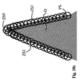
- FIG. 3 shown schematically. Shown here is enlarged in a Referenzprüfsent RPB a small section of a sawtooth-shaped reference object RO, whose sawtooth edge is to be tested accurately.
- an extracted contour K ie a pixel sequence which indicates the contour data
- the extraction of such a contour K can be performed by the usual methods such as a threshold method, an edge tracking method, etc. Smoothing or segmentation of the image to extract the contour can be done, for example, using morphological operators such as the. so-called opening and closing operators, dilation, erosion and skeletonization operators. Such morphological operators are well known in the art of image processing.
- the relevant data of the contour K such as the contour profile and the position and position of the contour K, are stored in a memory in method step IIa.
- a typical polygon approximation method which is suitable for this, is the so-called Ramer algorithm.
- program modules that can approximate a contour by a polygon, for example, that of the company MVtec.
- Such programs have hitherto been used for radius measurements or distance measurements.
- this method inevitably leads to precisely certain critical sections of the contour, for example the tips of the sawtooth structure, not being adapted exactly.
- FIG. 4 shows a so broken into test sections sections contour with several contour sections KA1, KA2, KA3, KA4, KA5, KA6, KA7, KA8, KA9.
- an offset can be recognized between the contour section KA5 and the contour section KA6.
- Such gaps between the contour sections KA1, KA2, KA3, KA4, KA5, KA6, KA7, KA8, KA9 will later be treated separately as well as certain other problematic places in the contour K during the test. This will be explained below.
- method step Ig a separate check is made as to whether the transitions between the individual contour sections are erratic or fluid. If such a sudden transition between two contour sections is detected, the adjacent contour sections are combined in method step Ig by a preferably straight line between the opposite ends of the contour sections to form a test section. The contour sections and the possibly inserted connecting lines then form the test track areas. Thus, the entire test section ultimately includes the determined contour sections KA1, KA2, KA3, KA4, KA5, KA6, KA7, KA8, KA9, which can each form individual test track sections, and the inserted connecting lines.
- a classification of different test track ranges into certain test track range classes also takes place simultaneously in accordance with previously defined classification rules. Ie.
- test section areas For example, sudden transitions between the individual test track sections or contour sections are classified as test section areas to be tested particularly, as well as test track areas which contain other particularly prominent points along the test track, eg. B. if two test sections in one acute angles abut each other.
- test track areas which contain other particularly prominent points along the test track, eg. B. if two test sections in one acute angles abut each other.
- test area classes or types of particularly striking test section areas are described below with reference to FIGS. 5 to 8c explained.
- Particularly straight or only slightly curved test sections, ie the test sections, which are formed by the determined in step Ie contour sections, yes have been sorted into a separate füriern GmbH, since these need not be subject to separate treatment.
- the data obtained in method step 1g over the entire test section and the classification of the test section areas are stored in step IIc.
- test track areas which fall into test track area classes which correspond to particularly marked transitions between test track sections or are themselves particularly distinctive test bed sections, according to certain test rules are provided with a test cell structure and for these possibly already determined reference values RW for the later test determined by test parameter values of the test cell.
- these reference values RW as well as information about the test cell structure are deposited at the relevant marked transitions.
- the data stored there in particular, is the cell geometry, for the definition of which in a circular cell the radius and the respective position of the center suffice.
- a test pattern PB is first recorded in method step IIIa. Again, if necessary, the area to be tested in step IIIb is selected, and this can be done automatically.
- step IIIc the stored contour is then searched for in the test image PB with an automatic method and its position, position and size deviation are determined in relation to the contour profile of the reference test object stored in memory in method step IIa. The position, position and size deviation can then be used to in the process step IIId from the memory in the process step IIb deposited simple geometrical introhalnabbalde or stored there form information and information about the position, location and size of these geometric objects and to adapt their position, location and size to the contour in the current test image.
- test section regions formed by the individual simple geometric test section sections and falling within the first test section class class can then be checked automatically.
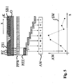
- FIG. 5 explains, in analogy to FIG. 1 a part of a test object O with a contour K is shown.
- the test section SB1 is occupied along the contour K in a scan direction x with test cells PZ, which overlap each other by a certain amount.
- test cells PZ are used as possible.
- a test cell structure ZS1 is constructed with all the equidistant, circular test cells PZ along the test section area SB.
- a mean gray value is then determined as the test parameter value PPW.
- An average gray value or average intensity value is simply the mean value of all the intensity values of the individual image pixels falling into the test cell PZ.
- test cell unit PZE four adjacent test cells PZ are combined into test cell units PZE, with two adjacent test cell units PZE each overlapping precisely by one test cell PZ, ie the test cell units PZG are moved with an advance of three test cells PZ in the scan direction x shifted.
- a maximum average intensity deviation value AW is then determined, ie the difference between the maximum intensity mean value PPW and the minimum intensity mean value PPW of the test cells PZ of the respective ones Test cell unit PZE determined. This gives the values in the third row.
- intensity deviation values AW are then compared with a threshold SW, which is shown in the diagram below in FIG. 5 is shown. If the intensity deviation value AW of a test cell unit is above the predetermined threshold value, this is detected as an error. If the intensity deviation value AW is below the threshold value, this area of the contour is in order.
- test cells PZ The size of the test cells PZ, the number of test cells PZ on the test area SB1 or the density of the test cells PZ and thus their overlap, the number of test cells PZ within a test cell unit PZE and the test cell feed and the threshold SW u. a. as test rules, for example, set by a user before and adapted to the respective test task or the desired sensitivity of the error check.
- end-side test cells PZ are each set so that their edges lie exactly on the end of the test section area SB1. This means that with an automatic determination of the test track such test track areas SB1 can also be brought directly to a corner of the object, without resulting in incorrectly recognized error messages that test cells unintentionally protrude laterally beyond the contour K in the scan direction x.
- test cell structures were separately determined for these other test section regions already in method step Ih and stored in a memory in method step IIc. These test cell structures are now in the Step IIIf again read from the memory and adapted to the corresponding striking test track areas of the test track in the current test image to be tested, the position and location of these individual test cells, but preferably not their size can be adjusted.
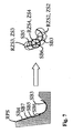
- FIG. 6 shows a case in which a test section has a curvature with a radius r below a predetermined limit radius.
- a test section is to be classified as a separate test section SB3, since this is based on FIG. 5 explained method is not particularly well suited for testing. Therefore, for example, a suitable test cell structure ZS2 is manually or automatically placed in the reference test pattern over this test section area SB3, wherein care is also taken here that the outermost test cells each end exactly with the test section or test section SB3.
- FIG. 7 shows a further case in which certain sections of the test track PS are particularly short. These are the test track sections SB5 and SB3, which are therefore for this reason to be classified as special test track areas SB5, SB3 and treated separately.
- the classification may therefore be made in accordance with the classification rules such that it is checked whether a test section has a length which is below a predetermined limit, for example one and a half times the diameter of the test cells, as they are to be used at the non-distinctive locations.
- a predetermined limit for example one and a half times the diameter of the test cells
- Test area could also fall into different test area categories, whereby the test rules specify according to which test rules for which test area class class a further treatment of this test area should take place.
- a corresponding test cell structure for such a short test section SB5 is shown.
- Shown here is again the test cell structure for the excessively curved test section area SB3 as well as the treatment of a transition area SB6 between the adjacent test cell areas SB5 and SB3, which here by a single test cell, which forms an independent test cell structure ZS4, so to speak.
- the treatment of such jump transitions is but below with reference to FIGS. 9a to 9c explained in more detail.
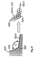
- FIG. 8 shows another test section class of a transition between two test track sections SB8, SB10, which abut each other at an acute angle ⁇ , which is smaller than a predetermined critical angle. That is, the test section area SB9 is formed by the end portions of the test areas SB8, SB10 abutting at the acute angle ⁇ formed by straight test section sections. Even at such corners is a continuous test with the in FIG. 5 explained automatic method in sufficiently good form not possible. Therefore, a test cell structure is preferably also defined here manually or automatically according to a predetermined test rule, which in turn is on the right side of FIG FIG. 8 is shown. According to the test rule set in this test area class, a test cell is placed directly on the boundary point and further test cells run laterally into the other test areas SB8, SB10.
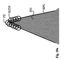
- FIG. 9a shows a case for a check range class formed by check ranges including a jump between two adjacent check distance portions.
- these are the test sections SB11 and SB13, each of which forms a test area SB11, SB13.
- the distance a between the ends this test section is greater than a predetermined limit distance. Therefore, this must be classified as a separate test area SB12.
- a test cell is set according to a certain, predetermined test rule, which bridges this distance a.
- the cell is placed here so that its center lies on the middle of the line connecting the ends of the test track areas SB11, SB13.
- further test cells are set, which run into the adjacent test areas SB11, SB13 respectively.
- Such a test cell structure ZS6 is on the right side of FIG FIG. 9a shown.
- FIGS. 9b and 9c show situations in which the distance a is even greater.
- FIG. 9b shows a case where the distance a is greater than a further set second limit distance.
- two cells are set, each having its center at the end point of the two spaced apart test sections SB11, SB13, and cells are again set to enter the adjacent test areas SB11, SB13.
- FIG. 9c finally shows a case in which the distance a exceeds an even wider border distance.
- three test cells are set, one in the middle of the connecting line between the ends of the test section sections SB11, SB13 and one cell at the two end points of the test section sections SB11, SB13 and, as usual, further test cells running into the test section sections SB11, SB13.
- test cell structures set manually or automatically according to the prescribed test rules within the reference test pattern are also adopted directly as reference test cell structures for the subsequent test and are merely adapted to the current test pattern with regard to their position. Therefore, in the FIGS. 6 to 9a at the same time, the test cell structures ZS2, ZS3, ZS4, ZS5, ZS6, ZS7, ZS8 were also provided with reference cell structures RZS2, RZS3, RZS4, RZS5, RZS6, RZS7, RZS8, so that in the figures the test cell structures were each given corresponding double reference numbers.
- the reference values are determined from the memory, which have also been deposited there in step IIc, and used to test striking test track areas using the test cell structures adopted from the reference test pattern.
- a variety of test rules can be used. For example, as reference values for each individual cell, a mean intensity value and additionally a difference of the mean intensity value to the respective neighbor test cell may have been deposited. Exactly these values are then also determined during the actual test for the individual test cells. In an evaluation in the context of the test, a comparison of the average intensity value of each test cell with the taught-in reference value can then take place. Likewise, however, it is also possible to compare the mean reference value with an absolute threshold value for each individual test cell.
- test rules are only examples, whereby a combination of different test rules can be used.
- the exact definition of the test rule should depend on the object to be tested or the specific contour as well as the striking distinctive areas or test areas occurring therein and the desired sensitivity of the test.
- test result is output, for example displayed in the form of an optical and / or acoustic warning signal to an operator and / or a control signal is output in order to sort out a faulty test object.
- FIG. 10a is a section of a sawtooth of the in FIG. 3 and 4 already shown test object shown.
- the outline became straight in two Contour sections and a tip forming, very strongly curved contour section divided. This peak, which contains the strongly curved contour section, forms a test area, which is classified into a separate test area class.
- a manual positioning of a reference test cell structure RZS9 was carried out during the teach-in process on the basis of a reference test image, in which exactly one test cell PZ is placed at the tip and further test cells protrude into the straight contour sections, so that they cover the test section areas of the reference zones adjacent to the tip.
- Overlap test section RPS of reference test object RO was carried out during the teach-in process on the basis of a reference test image, in which exactly one test cell PZ is placed at the tip and further test cells protrude into the straight contour sections, so that they cover the test section areas of the reference zones adjacent to the tip.
- Overlap test section RPS of reference test object RO Overlap test section RPS of reference test object RO.
- FIG. 10b shows how the test on the later test object O along these straight scholararyn Schemee using the structure of a simple automatic test cell structure ZS1 takes place, as already described with reference to FIG. 5 was explained.
- FIG. 10c shows, finally, as below in the test object O a check of the in FIG. 10b shown process step previously unexamined tip by the in FIG. 10a reference test cell structure RZS9 created and adjusted to the top of the test object O and then carried out with the help of this test cell ZS9 then the test of the tip.
- the overlap of the test cell structures ZS9 and ZS1 ensures that the entire contour of the sawtooth tip is checked.
- test cells are designed so that they approximate as well as possible a circular shape. How well such an approximation to a circular shape can take depends, among other things, on the image resolution. Particular preference is therefore given to setting the test cells in the sub-pixel range.
- the original image - which may be the reference test pattern or the test image, depending on whether the test cell is set in the reference test pattern or in the test pattern itself - is first enlarged. Subsequently, the test cell PZ is fitted. In FIG.
- the image is enlarged by a factor of 4, ie each pixel is replaced by a field of 4 x 4 pixels, the individual pixels of this 4 x 4 field each receiving the intensity value of the relevant pixel in the original image.
- the circle can be set so that it also runs centrally through the original pixels.
- This method has the advantage that edge pixels can be well weighted with low computational effort.
- the test cell itself can also be made smaller in relation to the contour, since incorrect positioning by a single pixel does not have as much influence. With smaller cells but again finer errors can be found, so that this method also contributes to the improvement of error detection.
- a central component of the test system according to FIG. 12 is a computer unit 10, to which a CCD camera 2 is connected as an image sensor unit 2 with a lens 3.
- the test objects O are positioned at a defined location in the receiving area of the camera 2 with the aid of a suitable positioning device or transport device (not shown).
- the camera 2 can be arranged directly on or above a conveyor belt of a production line.
- a reference object RO is positioned to match the camera 2, thus recording a reference test image RPB.
- the camera 2 is driven by an image acquisition unit 11, for example a so-called "frame grabber" 11.
- the CPU 14 in turn has access to this memory 12th
- input / output interfaces such as conventional COM interfaces, LPT interfaces, USB interfaces or other digital input and / or output interfaces, which are shown here as an interface block 13, a monitor 4 and one or more input devices 5, for example a mouse, a keyboard, etc. connected, which together form a user interface 6 with a graphical user interface.
- the input / output interfaces 13 are also connected to the CPU 14.
- the computer unit 10 has a permanent memory 15, for example a hard disk memory 15, to which the CPU 14 also has access.
- a test module 20 which includes various software modules required for the construction of the test system according to the invention.
- This image preprocessing module 21 can also be controlled via the user interface 6 and, for example, hereby the operator or automatically select a region to be checked in the image.
- the contour can also be smoothed.
- This image processing module 22 has as a subunit first a test track determination unit 23, which determines a well adapted to the contour test track.
- a test track classification unit 24 which, for example, in a reference test pattern RFB the test track by already using FIG. 2 determined method in the teaching process and after certain classification rules KR, which are stored for example in the memory 15, individual test track ranges classified in test track area classes BK or sorted and stored accordingly in the memory 15.
- this test track determination unit 23 can also be used to adapt an already stored reference test section RPS or the test section areas encompassed by the reference test section RPS to a contour of the current test pattern.
- a test cell determination unit 25 then serves to adapt to the test section (or in the case of learning to the reference test section) a test cell structure according to the predetermined test rules PR, which are likewise stored in the memory 15.
- This test cell determination unit 25 can also be controlled via the user interface 6, for example, in order to manually define test cell structures in certain prominent areas.
- this test cell determination unit 25 is also able to automatically define test cells according to the prescribed test rules PR, in particular in the context of a test of simple straight sections according to the test section areas of the first test section class described above.
- This test cell determination unit also has a test cell structure acquisition and adaptation unit 26 to accept reference test cell structures RPS, which have been stored in the learning process in the memory 15 for a specific reference object, and to a current test object O or the contour currently to be tested adapt.
- a test unit 27 then serves to check the contour on the basis of the specified test cell structures, as has already been explained in detail above.
- an output unit 28 provides an output of the test result, for example, in the form that the user is warned via the user interface 6 by outputting an acoustic and / or optical signal when a faulty test object O has been detected.
- a control signal STS are output, which drives, for example, a sorting of the (not shown) transport device, which sorts out a faulty detected test object.
Claims (11)
- Procédé pour le contrôle optique d'un contour (K) d'un objet de contrôle (O) avec les étapes suivantes du procédé :- prise d'une image de contrôle (PB) d'au moins une zone de contrôle d'un objet de contrôle (O) à contrôler,- établissement d'un segment de contrôle (PS) le long du contour (K) à contrôler à l'intérieur de l'image de contrôle (PB),- contrôle le long du segment de contrôle (PS) par balayage du contour (K) le long du segment de contrôle (PS) et détermination de valeurs de paramètres de contrôle (PPW) pour des cellules de contrôle (PZ) définies le long du segment de contrôle (PS), lesquelles cellules comprennent respectivement un certain nombre de points d'image,
et détection de différences par rapport à des valeurs de référence prescrites sur la base de valeurs de paramètres de contrôle (PPW) des cellules de contrôle (PZ),
moyennant quoi
les cellules de contrôle (PZ) présentent respectivement sensiblement une forme circulaire ou une forme polygonale convexe proche d'un cercle avec au moins cinq angles. - Procédé selon la revendication 1, caractérisé en ce que les valeurs de paramètres de contrôle (PPW) sont respectivement déterminées sur la base des valeurs moyennes d'intensité des valeurs d'intensité des points d'image individuels de la cellule de contrôle (PZ) respective.
- Procédé selon les revendications 1 ou 2, caractérisé en ce que l'on détermine tout d'abord un segment de contrôle de référence (RPS) dans une image de contrôle de référence (RPB), sur la base de laquelle on effectue une détermination d'un segment de contrôle (PS) à l'intérieur de l'image de contrôle (PB).
- Procédé selon l'une des revendications 1 à 3, caractérisé en ce que, pour la définition de cellules de contrôle (PZ) le long d'un segment de contrôle (PS) ou d'un segment de contrôle de référence (RPS), on agrandit tout d'abord l'image de contrôle (PB) ou l'image de contrôle de référence (RPB) en remplaçant ce faisant chaque point d'image par un champ de point d'image.
- Procédé selon l'une des revendications précédentes, caractérisé en ce qu'une cellule de contrôle (PZ) se situant à une extrémité d'une zone de segment de contrôle (SB1) est définie de manière à ce que l'extrémité en question de la zone de segment de contrôle (SB1) se situe sur un bord de la cellule de contrôle (PZ).
- Procédé selon l'une des revendications 1 à 5, caractérisé en ce que le segment de contrôle (PS) comprend un certain nombre de zones de segment de contrôle (SB1, SB2, SB3, SB4, SB5, SB6, SB7, SB8, SB9, SB10, SB11, SB12, SB13), lesquelles sont respectivement classées en classes de zones de segment de contrôle (BK) définies selon des règles de classification (KR) prescrites, et en ce que l'on définit, conformément aux règles de contrôle (PR) prescrites pour la classe de zones de segment de contrôle (BK) respective le long des zones de segment de contrôle (SB1, SB2, SB3, SB4, SB5, SB6, SB7, SB8, SB9, SB10, SB11, SB12, SB13) du segment de contrôle (PS), respectivement une structure de cellules de contrôle (ZS1, ZS2, ZS3, ZS4, ZS5, ZS6, ZS7, ZS8, ZS9) se composant d'un certain nombre de cellules de contrôle (PZ), et des valeurs de paramètres de contrôle (PPW) étant déterminées pour les cellules de contrôle (PZ) individuelles, et en ce qu'un contrôle de l'objet de contrôle le long des zones de segment de contrôle (SB1, SB2, SB3, SB4, SB5, SB6, SB7, SB8, SB9, SB10, SB11, SB12, SB13) individuelles est effectué sur la base des valeurs de paramètres de contrôle (PPW) des cellules de contrôle (PZ) conformément à des règles de contrôle (PR) prescrites pour la classe de zones de segment de contrôle (BK) respective.
- Procédé selon la revendication 6, caractérisé en ce que l'on définit tout d'abord, dans une image de contrôle de référence (RPB), le long d'une zone de segment de contrôle (SB1, SB2, SB3, SB4, SB5, SB6, SB7, SBB, SB9, SB10, SB11, SB12, SB13) du segment de contrôle de référence (RPS), une structure de cellules de contrôle de référence (RZS1, RZS2, RZS3, RZS4, RZS5, RZS6, RZS7, RZS8, RZS9) et sur les bases de celle-ci, une définition d'une structure de cellules de contrôle (ZS1, ZS2, ZS3, ZS4, ZS5, ZS6, ZS7, ZS8, ZS9) ayant lieu le long d'une zone de segment de contrôle (SB1, SB2, SB3, SB4, SB5, SB6, SB7, SB8, SB9, SB10, SB11, SB12, SB13) du segment de contrôle (PS) d'un objet de contrôle (O) à contrôler actuellement.
- Procédé selon la revendication 7, caractérisé en ce que l'on détermine, sur la base de valeurs de paramètres de contrôle (PPW) de cellules de contrôle (PZ) de la structure de cellules de contrôle (RZS1, RZS2, RZS3, RZS4, RZS5, RZS6, RZS7, RZS8, RZS9), des valeurs de référence (RW) pour un contrôle ultérieur d'un objet de contrôle (O).
- Procédé selon l'une des revendications 6 à 8, caractérisé en ce que, pour des zones de segment de contrôle (SB1, SB8, SB9, SB11, SB13) d'au moins l'une de classes de zones de contrôle, on effectue une définition automatique d'une structure de cellules de contrôle (ZS1) conformément à une première règle de structuration de cellules de contrôle
et en ce que, pour des zones de segment de contrôle (SB2, SB3, SB4, SB5, SB6, SB7, SB10, SB12) d'au moins une autre des classes de zones de contrôle, on effectue une définition automatique et/ou manuelle d'une structure de cellules de contrôle (ZS2, ZS3, ZS4, ZS5, ZS6, ZS7, ZS8, ZS9) conformément à au moins une deuxième règle de structuration de cellules de contrôle. - Système de contrôle (1) pour le contrôle optique d'un contour (K) d'un objet de contrôle (O), avec- une unité de capteur d'image (2) pour la prise d'une image de contrôle (PB, RPB) d'au moins une zone de contrôle d'un objet de contrôle (O, RO),- une unité de détermination de segment de contrôle (23) pour déterminer un segment de contrôle (PS) le long du contour (K) à contrôler à l'intérieur de l'image de contrôle,- une unité de détermination de cellules de contrôle (25) pour la définition de cellules de contrôle (PZ) comprenant respectivement un certain nombre de points d'image le long du segment de contrôle (PS) et pour la détermination de valeurs de paramètres de contrôle (PPW) pour les cellules de contrôle (PZ) individuelles,- une unité de contrôle (27) pour le contrôle le long du segment de contrôle (PS) grâce à un balayage du contour (K) le long du segment de contrôle (PS) et pour la détection de différences par rapport à des valeurs de référence prescrites sur la base des valeurs de paramètres de contrôle des cellules de contrôle (PZ),- une unité de sortie (28) pour la sortie du résultat de contrôle,
l'unité de détermination de cellules de contrôle (25) étant réalisée de manière à ce que les cellules de contrôle (PZ) présentent respectivement sensiblement une forme circulaire ou une forme polygonale convexe proche d'un cercle avec au moins cinq angles. - Produit de programme informatique, lequel peut être directement chargé dans une mémoire d'une unité de informatique (10) programmable d'un système de contrôle (1), avec des moyens de codes de programme afin d'exécuter toutes les étapes d'un procédé selon l'une des revendications 1 à 9 lorsque le programme est exécuté sur l'unité de informatique (10).
Applications Claiming Priority (2)
| Application Number | Priority Date | Filing Date | Title |
|---|---|---|---|
| DE200810049858 DE102008049858B4 (de) | 2008-10-01 | 2008-10-01 | Verfahren und Prüfsystem zur optischen Prüfung eines Prüfobjekts |
| PCT/EP2009/006868 WO2010037492A1 (fr) | 2008-10-01 | 2009-09-23 | Procédé et système de contrôle pour réaliser un contrôle optique d'un objet |
Publications (2)
| Publication Number | Publication Date |
|---|---|
| EP2353143A1 EP2353143A1 (fr) | 2011-08-10 |
| EP2353143B1 true EP2353143B1 (fr) | 2014-06-18 |
Family
ID=41338702
Family Applications (1)
| Application Number | Title | Priority Date | Filing Date |
|---|---|---|---|
| EP09778669.3A Active EP2353143B1 (fr) | 2008-10-01 | 2009-09-23 | Procédé et système de contrôle pour réaliser un contrôle optique d'un objet |
Country Status (3)
| Country | Link |
|---|---|
| EP (1) | EP2353143B1 (fr) |
| DE (1) | DE102008049858B4 (fr) |
| WO (1) | WO2010037492A1 (fr) |
Family Cites Families (6)
| Publication number | Priority date | Publication date | Assignee | Title |
|---|---|---|---|---|
| EP0163885A1 (fr) * | 1984-05-11 | 1985-12-11 | Siemens Aktiengesellschaft | Dispositif de segmentation de lignes |
| US5923430A (en) * | 1993-06-17 | 1999-07-13 | Ultrapointe Corporation | Method for characterizing defects on semiconductor wafers |
| US6718074B1 (en) * | 2000-06-02 | 2004-04-06 | Cognex Corporation | Method and apparatus for inspection for under-resolved features in digital images |
| JP2006170922A (ja) * | 2004-12-20 | 2006-06-29 | Topcon Corp | 外観検査方法およびその装置 |
| JP4323475B2 (ja) | 2005-09-26 | 2009-09-02 | アドバンスド・マスク・インスペクション・テクノロジー株式会社 | 試料検査装置、試料検査方法及びプログラム |
| DE102006060741A1 (de) | 2006-12-21 | 2008-06-26 | Henkel Kgaa | Verfahren und Vorrichtung zur optischen Prüfung von Objekten |
-
2008
- 2008-10-01 DE DE200810049858 patent/DE102008049858B4/de active Active
-
2009
- 2009-09-23 EP EP09778669.3A patent/EP2353143B1/fr active Active
- 2009-09-23 WO PCT/EP2009/006868 patent/WO2010037492A1/fr active Application Filing
Also Published As
| Publication number | Publication date |
|---|---|
| EP2353143A1 (fr) | 2011-08-10 |
| DE102008049858B4 (de) | 2013-07-11 |
| WO2010037492A1 (fr) | 2010-04-08 |
| DE102008049858A1 (de) | 2010-04-29 |
Similar Documents
| Publication | Publication Date | Title |
|---|---|---|
| EP3432266B1 (fr) | Procédé et dispositif de détection de défauts | |
| EP2732236B1 (fr) | Dispositif et procédé optiques de contrôle de pneumatiques | |
| DE10011200A1 (de) | Verfahren zur Bewertung von Strukturfehlern auf einer Waferoberfläche | |
| EP3070674B1 (fr) | Procédé d'évaluation de qualité d'un composant fabriqué selon le procédé de fabrication additive | |
| DE102005011237B3 (de) | Verfahren zur Bestimmung von Defekten in Bildern | |
| DE2518077B2 (de) | System zum Feststellen der Winkelorientierung eines Durchlaufteiles relativ zu einem Probeteil | |
| EP3881968A1 (fr) | Procédé de détermination de l'état d'usure d'un outil | |
| DE10240877A1 (de) | Fehlerklassifikations-/Inspektions-System | |
| DE4201514A1 (de) | Verfahren zur ermittlung von fehlerhaften stellen | |
| EP2787485B1 (fr) | Procédé et dispositif de détection automatique d'erreurs dans des corps flexibles | |
| EP3786620A1 (fr) | Procédé et produit programme informatique pour la détection automatisée d'erreurs d'une boroscopie sur moteur | |
| DE102020120887B4 (de) | Verfahren zum erfassen einer einhängeposition eines auflagestegs und flachbettwerkzeugmaschine | |
| EP2345004B1 (fr) | Procédé et système de contrôle pour réaliser un contrôle optique du contour d'un objet | |
| WO2001023869A1 (fr) | Procede et dispositif pour inspecter la surface d'un feuillard circulant en continu | |
| EP2353143B1 (fr) | Procédé et système de contrôle pour réaliser un contrôle optique d'un objet | |
| WO2012059445A1 (fr) | Procédé et dispositif d'évaluation servant à déterminer la position d'une structure se trouvant dans un objet à examiner au moyen d'une tomographie aux rayons x assistée par ordinateur | |
| EP1988506A2 (fr) | Procédé de détermination automatique de la zone de contrôle, procédé de contrôle et système de contrôle | |
| DE4324800C2 (de) | Vorrichtung zur Bestimmung von Fehlern von Oberflächen hoher Güte | |
| EP1139285B1 (fr) | Procédé et dispositif pour contrôle ou inspection d'objets | |
| DE102019131437A1 (de) | Computerimplementiertes Verfahren zur Segmentierung von Messdaten aus einer Messung eines Objekts | |
| DE102022204406B4 (de) | Verfahren zum Klassifizieren und/oder zur Regression von Eingangssignalen unter Zuhilfenahme einer Gram-Matrix-Variante | |
| EP3825959B1 (fr) | Procédé mis en uvre par ordinateur destiné à la segmentation des données de mesure à partir d'une mesure d'un objet | |
| DE69819980T2 (de) | Verfahren zur Bestimmung eines Lederschnittmusters | |
| EP2799847B1 (fr) | Procédé de contrôle optique de surfaces d'objets | |
| EP3798570B1 (fr) | Procédé d'étalonnage d'un système de mesure optique, système de mesure optique et objet d'étalonnage pour un système de mesure optique |
Legal Events
| Date | Code | Title | Description |
|---|---|---|---|
| PUAI | Public reference made under article 153(3) epc to a published international application that has entered the european phase |
Free format text: ORIGINAL CODE: 0009012 |
|
| 17P | Request for examination filed |
Effective date: 20110406 |
|
| AK | Designated contracting states |
Kind code of ref document: A1 Designated state(s): AT BE BG CH CY CZ DE DK EE ES FI FR GB GR HR HU IE IS IT LI LT LU LV MC MK MT NL NO PL PT RO SE SI SK SM TR |
|
| DAX | Request for extension of the european patent (deleted) | ||
| 17Q | First examination report despatched |
Effective date: 20130104 |
|
| GRAP | Despatch of communication of intention to grant a patent |
Free format text: ORIGINAL CODE: EPIDOSNIGR1 |
|
| INTG | Intention to grant announced |
Effective date: 20131203 |
|
| GRAS | Grant fee paid |
Free format text: ORIGINAL CODE: EPIDOSNIGR3 |
|
| GRAP | Despatch of communication of intention to grant a patent |
Free format text: ORIGINAL CODE: EPIDOSNIGR1 |
|
| INTG | Intention to grant announced |
Effective date: 20140410 |
|
| GRAS | Grant fee paid |
Free format text: ORIGINAL CODE: EPIDOSNIGR3 |
|
| GRAA | (expected) grant |
Free format text: ORIGINAL CODE: 0009210 |
|
| AK | Designated contracting states |
Kind code of ref document: B1 Designated state(s): AT BE BG CH CY CZ DE DK EE ES FI FR GB GR HR HU IE IS IT LI LT LU LV MC MK MT NL NO PL PT RO SE SI SK SM TR |
|
| REG | Reference to a national code |
Ref country code: GB Ref legal event code: FG4D Free format text: NOT ENGLISH |
|
| REG | Reference to a national code |
Ref country code: CH Ref legal event code: EP |
|
| REG | Reference to a national code |
Ref country code: CH Ref legal event code: NV Representative=s name: ALDO ROEMPLER PATENTANWALT, CH Ref country code: AT Ref legal event code: REF Ref document number: 673713 Country of ref document: AT Kind code of ref document: T Effective date: 20140715 |
|
| REG | Reference to a national code |
Ref country code: IE Ref legal event code: FG4D Free format text: LANGUAGE OF EP DOCUMENT: GERMAN |
|
| REG | Reference to a national code |
Ref country code: DE Ref legal event code: R096 Ref document number: 502009009541 Country of ref document: DE Effective date: 20140731 |
|
| PG25 | Lapsed in a contracting state [announced via postgrant information from national office to epo] |
Ref country code: NO Free format text: LAPSE BECAUSE OF FAILURE TO SUBMIT A TRANSLATION OF THE DESCRIPTION OR TO PAY THE FEE WITHIN THE PRESCRIBED TIME-LIMIT Effective date: 20140918 Ref country code: LT Free format text: LAPSE BECAUSE OF FAILURE TO SUBMIT A TRANSLATION OF THE DESCRIPTION OR TO PAY THE FEE WITHIN THE PRESCRIBED TIME-LIMIT Effective date: 20140618 Ref country code: FI Free format text: LAPSE BECAUSE OF FAILURE TO SUBMIT A TRANSLATION OF THE DESCRIPTION OR TO PAY THE FEE WITHIN THE PRESCRIBED TIME-LIMIT Effective date: 20140618 Ref country code: GR Free format text: LAPSE BECAUSE OF FAILURE TO SUBMIT A TRANSLATION OF THE DESCRIPTION OR TO PAY THE FEE WITHIN THE PRESCRIBED TIME-LIMIT Effective date: 20140919 Ref country code: CY Free format text: LAPSE BECAUSE OF FAILURE TO SUBMIT A TRANSLATION OF THE DESCRIPTION OR TO PAY THE FEE WITHIN THE PRESCRIBED TIME-LIMIT Effective date: 20140618 |
|
| REG | Reference to a national code |
Ref country code: NL Ref legal event code: VDEP Effective date: 20140618 |
|
| REG | Reference to a national code |
Ref country code: LT Ref legal event code: MG4D |
|
| PG25 | Lapsed in a contracting state [announced via postgrant information from national office to epo] |
Ref country code: LV Free format text: LAPSE BECAUSE OF FAILURE TO SUBMIT A TRANSLATION OF THE DESCRIPTION OR TO PAY THE FEE WITHIN THE PRESCRIBED TIME-LIMIT Effective date: 20140618 Ref country code: HR Free format text: LAPSE BECAUSE OF FAILURE TO SUBMIT A TRANSLATION OF THE DESCRIPTION OR TO PAY THE FEE WITHIN THE PRESCRIBED TIME-LIMIT Effective date: 20140618 Ref country code: SE Free format text: LAPSE BECAUSE OF FAILURE TO SUBMIT A TRANSLATION OF THE DESCRIPTION OR TO PAY THE FEE WITHIN THE PRESCRIBED TIME-LIMIT Effective date: 20140618 |
|
| PG25 | Lapsed in a contracting state [announced via postgrant information from national office to epo] |
Ref country code: SK Free format text: LAPSE BECAUSE OF FAILURE TO SUBMIT A TRANSLATION OF THE DESCRIPTION OR TO PAY THE FEE WITHIN THE PRESCRIBED TIME-LIMIT Effective date: 20140618 Ref country code: PT Free format text: LAPSE BECAUSE OF FAILURE TO SUBMIT A TRANSLATION OF THE DESCRIPTION OR TO PAY THE FEE WITHIN THE PRESCRIBED TIME-LIMIT Effective date: 20141020 Ref country code: RO Free format text: LAPSE BECAUSE OF FAILURE TO SUBMIT A TRANSLATION OF THE DESCRIPTION OR TO PAY THE FEE WITHIN THE PRESCRIBED TIME-LIMIT Effective date: 20140618 Ref country code: EE Free format text: LAPSE BECAUSE OF FAILURE TO SUBMIT A TRANSLATION OF THE DESCRIPTION OR TO PAY THE FEE WITHIN THE PRESCRIBED TIME-LIMIT Effective date: 20140618 Ref country code: ES Free format text: LAPSE BECAUSE OF FAILURE TO SUBMIT A TRANSLATION OF THE DESCRIPTION OR TO PAY THE FEE WITHIN THE PRESCRIBED TIME-LIMIT Effective date: 20140618 Ref country code: CZ Free format text: LAPSE BECAUSE OF FAILURE TO SUBMIT A TRANSLATION OF THE DESCRIPTION OR TO PAY THE FEE WITHIN THE PRESCRIBED TIME-LIMIT Effective date: 20140618 |
|
| PG25 | Lapsed in a contracting state [announced via postgrant information from national office to epo] |
Ref country code: NL Free format text: LAPSE BECAUSE OF FAILURE TO SUBMIT A TRANSLATION OF THE DESCRIPTION OR TO PAY THE FEE WITHIN THE PRESCRIBED TIME-LIMIT Effective date: 20140618 Ref country code: PL Free format text: LAPSE BECAUSE OF FAILURE TO SUBMIT A TRANSLATION OF THE DESCRIPTION OR TO PAY THE FEE WITHIN THE PRESCRIBED TIME-LIMIT Effective date: 20140618 Ref country code: IS Free format text: LAPSE BECAUSE OF FAILURE TO SUBMIT A TRANSLATION OF THE DESCRIPTION OR TO PAY THE FEE WITHIN THE PRESCRIBED TIME-LIMIT Effective date: 20141018 |
|
| REG | Reference to a national code |
Ref country code: DE Ref legal event code: R097 Ref document number: 502009009541 Country of ref document: DE |
|
| PLBE | No opposition filed within time limit |
Free format text: ORIGINAL CODE: 0009261 |
|
| STAA | Information on the status of an ep patent application or granted ep patent |
Free format text: STATUS: NO OPPOSITION FILED WITHIN TIME LIMIT |
|
| PG25 | Lapsed in a contracting state [announced via postgrant information from national office to epo] |
Ref country code: MC Free format text: LAPSE BECAUSE OF FAILURE TO SUBMIT A TRANSLATION OF THE DESCRIPTION OR TO PAY THE FEE WITHIN THE PRESCRIBED TIME-LIMIT Effective date: 20140618 Ref country code: DK Free format text: LAPSE BECAUSE OF FAILURE TO SUBMIT A TRANSLATION OF THE DESCRIPTION OR TO PAY THE FEE WITHIN THE PRESCRIBED TIME-LIMIT Effective date: 20140618 Ref country code: LU Free format text: LAPSE BECAUSE OF FAILURE TO SUBMIT A TRANSLATION OF THE DESCRIPTION OR TO PAY THE FEE WITHIN THE PRESCRIBED TIME-LIMIT Effective date: 20140923 Ref country code: IT Free format text: LAPSE BECAUSE OF FAILURE TO SUBMIT A TRANSLATION OF THE DESCRIPTION OR TO PAY THE FEE WITHIN THE PRESCRIBED TIME-LIMIT Effective date: 20140618 |
|
| 26N | No opposition filed |
Effective date: 20150319 |
|
| REG | Reference to a national code |
Ref country code: IE Ref legal event code: MM4A |
|
| PG25 | Lapsed in a contracting state [announced via postgrant information from national office to epo] |
Ref country code: BE Free format text: LAPSE BECAUSE OF NON-PAYMENT OF DUE FEES Effective date: 20140930 |
|
| PG25 | Lapsed in a contracting state [announced via postgrant information from national office to epo] |
Ref country code: SI Free format text: LAPSE BECAUSE OF FAILURE TO SUBMIT A TRANSLATION OF THE DESCRIPTION OR TO PAY THE FEE WITHIN THE PRESCRIBED TIME-LIMIT Effective date: 20140618 |
|
| PG25 | Lapsed in a contracting state [announced via postgrant information from national office to epo] |
Ref country code: IE Free format text: LAPSE BECAUSE OF NON-PAYMENT OF DUE FEES Effective date: 20140923 |
|
| REG | Reference to a national code |
Ref country code: FR Ref legal event code: PLFP Year of fee payment: 7 |
|
| PG25 | Lapsed in a contracting state [announced via postgrant information from national office to epo] |
Ref country code: SM Free format text: LAPSE BECAUSE OF FAILURE TO SUBMIT A TRANSLATION OF THE DESCRIPTION OR TO PAY THE FEE WITHIN THE PRESCRIBED TIME-LIMIT Effective date: 20140618 |
|
| REG | Reference to a national code |
Ref country code: CH Ref legal event code: PCOW Free format text: NEW ADDRESS: ROBERT-KOCH-STRASSE 100, 85521 OTTOBRUNN (DE) |
|
| REG | Reference to a national code |
Ref country code: DE Ref legal event code: R082 Ref document number: 502009009541 Country of ref document: DE Representative=s name: BECKORD & NIEDLICH PATENTANWALTSKANZLEI, DE Ref country code: DE Ref legal event code: R081 Ref document number: 502009009541 Country of ref document: DE Owner name: PANASONIC ELECTRIC WORKS EUROPE AG, DE Free format text: FORMER OWNER: PANASONIC ELECTRIC WORKS EUROPE AG, 83607 HOLZKIRCHEN, DE Ref country code: DE Ref legal event code: R082 Ref document number: 502009009541 Country of ref document: DE Representative=s name: BECKORD & NIEDLICH PATENTANWAELTE PARTG MBB, DE |
|
| PG25 | Lapsed in a contracting state [announced via postgrant information from national office to epo] |
Ref country code: MT Free format text: LAPSE BECAUSE OF FAILURE TO SUBMIT A TRANSLATION OF THE DESCRIPTION OR TO PAY THE FEE WITHIN THE PRESCRIBED TIME-LIMIT Effective date: 20140618 Ref country code: BG Free format text: LAPSE BECAUSE OF FAILURE TO SUBMIT A TRANSLATION OF THE DESCRIPTION OR TO PAY THE FEE WITHIN THE PRESCRIBED TIME-LIMIT Effective date: 20140618 |
|
| PG25 | Lapsed in a contracting state [announced via postgrant information from national office to epo] |
Ref country code: TR Free format text: LAPSE BECAUSE OF FAILURE TO SUBMIT A TRANSLATION OF THE DESCRIPTION OR TO PAY THE FEE WITHIN THE PRESCRIBED TIME-LIMIT Effective date: 20140618 Ref country code: HU Free format text: LAPSE BECAUSE OF FAILURE TO SUBMIT A TRANSLATION OF THE DESCRIPTION OR TO PAY THE FEE WITHIN THE PRESCRIBED TIME-LIMIT; INVALID AB INITIO Effective date: 20090923 |
|
| REG | Reference to a national code |
Ref country code: FR Ref legal event code: PLFP Year of fee payment: 8 |
|
| REG | Reference to a national code |
Ref country code: FR Ref legal event code: CA Effective date: 20160822 |
|
| REG | Reference to a national code |
Ref country code: FR Ref legal event code: PLFP Year of fee payment: 9 |
|
| PG25 | Lapsed in a contracting state [announced via postgrant information from national office to epo] |
Ref country code: MK Free format text: LAPSE BECAUSE OF FAILURE TO SUBMIT A TRANSLATION OF THE DESCRIPTION OR TO PAY THE FEE WITHIN THE PRESCRIBED TIME-LIMIT Effective date: 20140618 |
|
| REG | Reference to a national code |
Ref country code: FR Ref legal event code: PLFP Year of fee payment: 10 |
|
| PGFP | Annual fee paid to national office [announced via postgrant information from national office to epo] |
Ref country code: GB Payment date: 20220927 Year of fee payment: 14 Ref country code: DE Payment date: 20220920 Year of fee payment: 14 Ref country code: AT Payment date: 20220919 Year of fee payment: 14 |
|
| PGFP | Annual fee paid to national office [announced via postgrant information from national office to epo] |
Ref country code: FR Payment date: 20220920 Year of fee payment: 14 |
|
| PGFP | Annual fee paid to national office [announced via postgrant information from national office to epo] |
Ref country code: CH Payment date: 20220928 Year of fee payment: 14 |
|
| REG | Reference to a national code |
Ref country code: CH Ref legal event code: PL |