EP3798570B1 - Procédé d'étalonnage d'un système de mesure optique, système de mesure optique et objet d'étalonnage pour un système de mesure optique - Google Patents
Procédé d'étalonnage d'un système de mesure optique, système de mesure optique et objet d'étalonnage pour un système de mesure optique Download PDFInfo
- Publication number
- EP3798570B1 EP3798570B1 EP19200257.4A EP19200257A EP3798570B1 EP 3798570 B1 EP3798570 B1 EP 3798570B1 EP 19200257 A EP19200257 A EP 19200257A EP 3798570 B1 EP3798570 B1 EP 3798570B1
- Authority
- EP
- European Patent Office
- Prior art keywords
- calibration object
- calibration
- sensor
- plane
- mapping
- Prior art date
- Legal status (The legal status is an assumption and is not a legal conclusion. Google has not performed a legal analysis and makes no representation as to the accuracy of the status listed.)
- Active
Links
Images


Classifications
-
- G—PHYSICS
- G01—MEASURING; TESTING
- G01B—MEASURING LENGTH, THICKNESS OR SIMILAR LINEAR DIMENSIONS; MEASURING ANGLES; MEASURING AREAS; MEASURING IRREGULARITIES OF SURFACES OR CONTOURS
- G01B21/00—Measuring arrangements or details thereof, where the measuring technique is not covered by the other groups of this subclass, unspecified or not relevant
- G01B21/02—Measuring arrangements or details thereof, where the measuring technique is not covered by the other groups of this subclass, unspecified or not relevant for measuring length, width, or thickness
- G01B21/04—Measuring arrangements or details thereof, where the measuring technique is not covered by the other groups of this subclass, unspecified or not relevant for measuring length, width, or thickness by measuring coordinates of points
- G01B21/042—Calibration or calibration artifacts
-
- G—PHYSICS
- G01—MEASURING; TESTING
- G01B—MEASURING LENGTH, THICKNESS OR SIMILAR LINEAR DIMENSIONS; MEASURING ANGLES; MEASURING AREAS; MEASURING IRREGULARITIES OF SURFACES OR CONTOURS
- G01B11/00—Measuring arrangements characterised by the use of optical techniques
- G01B11/24—Measuring arrangements characterised by the use of optical techniques for measuring contours or curvatures
- G01B11/25—Measuring arrangements characterised by the use of optical techniques for measuring contours or curvatures by projecting a pattern, e.g. one or more lines, moiré fringes on the object
Definitions
- the present invention relates to a method for calibrating an optical measuring system, an optical measuring system and an optical measuring system with a calibration object for calibrating the optical measuring system.
- US 2011/288 806 A1 describes a method for calibrating a measurement system.
- structured light is projected onto a first, linear profile in order to carry out a linear calibration.
- a non-linear calibration is carried out using a further homography profile.
- JP H04 172213 A describes a calibration method in which images of a calibration object are captured at known positions.
- U.S. 2014/078260 A1 describes a method for detecting three-dimensional points, a predetermined pattern being projected onto an object for a calibration process.
- CN 107 218 904 A describes a method of calibrating a sensor using a sawtooth target to compensate for non-linear lens errors.
- So-called depth cameras can be used to measure the surface of an object.
- a system with a depth camera includes, for example, a light source that illuminates the object to be measured and an optical sensor.
- the light source such as a laser, projects a plane of light onto the object to be measured.
- an optical system can be provided between the object to be measured and the sensor, which focuses the light reflected by the object to be measured onto the sensor.
- the light source, the object to be measured and the sensor are usually arranged at a distance from one another, it being possible for the individual elements to be arranged at the corner points of a virtual triangle.
- mapping rule In order to measure an object, it is necessary to determine the mapping rule from the light plane in which the object to be measured is located to the sensor plane in which the sensor is located. In addition to this generally linear imaging, other non-linear distortions can occur due to the optics between the object and the sensor. These non-linear distortions due to lens errors or the like must also be compensated for.
- the non-linear components are determined, which are caused, for example, by the optics between the object and the sensor. After these non-linear components have been determined, a linear mapping from the light plane to the sensor plane can be determined in a further, separate step, in which the previously determined non-linear errors have been eliminated.
- the position of a calibration object in the light plane must generally be known in order to be able to determine the mapping rule from the light plane to the sensor plane.
- the effort for calibrating the optical measuring system should be reduced.
- the requirements for the user during the calibration process should also be simplified.
- the present invention creates a method for calibrating an optical measuring system and an optical measuring system with the features of the independent patent claims. Further advantageous embodiments are the subject matter of the dependent patent claims.
- an optical measuring system according to independent claim 8 is provided.
- an optical measuring system with a calibration object according to dependent claims 11 and 12 is provided.
- the calibration object has several edges. In particular, some of the edges can intersect at corner points.
- the calibration object can have a sawtooth structure.
- the present invention is based on the finding that the calibration of an optical measuring system is an expensive, complex and therefore also time-consuming process.
- non-linear distortions which are caused, for example, by optics between the object to be measured and the sensor, and the linear mapping from the light plane to the sensor plane with compensated non-linear distortions, must first be determined separately.
- the positions of the objects to be measured must be known as precisely as possible during the calibration process. This requires very precise positioning of the objects in the light plane.
- the non-linear components and the linear components for imaging from the light plane into the sensor plane are jointly determined in a single calibration step.
- the optical measuring system can be calibrated using a calibration object that can be moved freely in the measuring range of the light plane during the calibration object. A positioning of the calibration object at precisely specified positions and/or with precisely specified alignments during the calibration process is not necessary.
- the optical measuring system captures multiple images of the calibrated object at different positions. For example, at least 30 or 50 recordings of the calibrated object can be recorded for the calibration. However, a different number of, for example a larger number, such as 100, 200 or even more recordings of the calibrated object is also possible.
- the calibration process of the optical measuring system is carried out using only a single calibration object.
- This calibration object is suitable for determining both the non-linear and the linear components of the image from the light level to the sensor level.
- the measuring system can be, for example, a measuring system that optically detects an object illuminated by a light source.
- the object can be illuminated by means of a light source, for example a laser or the like.
- the light source can illuminate the object to be measured with a predetermined light pattern.
- the object can be illuminated with coherent light.
- the light reflected by the object is then imaged onto the sensor plane of the optical sensor by means of the optics.
- the sensor can thus provide image data from the object, which can be evaluated for further processing.
- the further processing can include, for example, an analysis of the surface of the object to be measured.
- any other processes for evaluating the image data of the object are also possible.
- the raw image data from the sensor can first be processed using a known mapping from the light plane in which the object is located to the sensor plane in which the sensor captures the image data.
- optical distortions or the like which are caused, for example, by the optics, can also be compensated for if necessary.
- the step of detecting the corner points in the recordings of the calibration object can include detecting edges in the recordings of the calibration object.
- the detected edges can then be evaluated in order to to determine intersections of the detected edges. These intersections of the edges correspond to corner points in the recordings of the calibration object.
- the corner points in the recordings of the calibration object can be determined easily and yet precisely.
- the accuracy of the positions of the corner points detected in this way can be increased on the basis of detected line profiles. Any suitable known or novel method can be used to detect the lines and to determine the intersection points of the lines.
- the detected corner points in the recordings of the calibration object are assigned to the corresponding positions on the calibration object using relative relationships.
- relative relationships of detected corner points in the recordings of the calibration object can be set in relation to relative relationships of predetermined positions in the calibration object.
- the predetermined positions in the calibration object can in particular be corner points in the calibration object.
- the recordings of the illuminated calibration object can be recorded at a plurality of spatially different positions. Furthermore, the recordings of the calibration object can be recorded with different alignments of the calibration object. This can be achieved, for example, in that the calibration object is moved in a translatory and/or rotary manner in the light plane. In this case, rotational movements of the calibration object are expressly possible and permitted. The exact position or alignment of the calibration object does not have to be known. This means that the calibration object can move freely in the light plane during the calibration process be moved. This can be done, for example, by manually moving the calibration object in the light plane. Of course, a machine-supported movement of the calibration object using a suitable device or the like can also be used.
- the spatial positions at which an image of the calibration object is recorded extend across the light plane to be calibrated.
- the positioning of the calibration object should extend over the widest possible area of the light plane that is to be calibrated during the calibration process.
- the calibration method includes a step for issuing instructions for positioning the calibration object.
- These instructions can be shown on a display, for example, or can be output as acoustic instructions. In this way, a user can be guided during the calibration process so that the calibration object is guided over all required areas of the light plane.
- the instructions can also include control commands that control a fully or partially automated device for positioning the calibration object.
- the image determined during the calibration is determined using multiple recordings of a calibration object, with the recordings each capturing the same calibration object.
- the calibration process can be performed using a single calibration object.
- no different calibration objects are required for determining linear imaging components and non-linear imaging components.
- the map determined includes a combination of a linear map and a non-linear map. This combination is determined in a single, joint calculation process. Thus, no separate processes are expressly required for determining a non-linear image, for example for lens distortions or the like, and a linear image.
- the mapping comprises a polynomial mapping.
- the polynomial mapping can have a predetermined degree.
- it can be a fourth degree polynomial mapping.
- polynomial mappings with a different degree for example two or three or even more than four, for example five, six or more, are also possible.
- the information about the calibration object in particular characteristic data such as predetermined corner points in the calibration object, is known in advance.
- this characteristic data about a calibration object can be stored in a memory and made available when required. If several calibration objects are to be available for selection, for example for different purposes of use, then the memory can also provide characteristic data for several calibration objects.
- the calibration object can in particular be a calibration object which has a number of corner points, in particular corner points at which a number of edges intersect in each case.
- a calibration profile with a sawtooth profile would be possible.
- the calibration profile can have a plurality of sawtooth structures that are offset relative to one another.
- the calibration profile can have, for example, two or more sawtooth structures that are offset relative to one another.
- other calibration profiles with suitable structures are also possible, which have multiple corners. Calibration profiles are particularly advantageous in which the individual corners are in a relative position to one another, which can still be reliably detected and assigned even if the calibration profile is rotated.
- FIG 1 shows a schematic representation of a basic diagram of a measuring system 1 according to an embodiment.
- the measuring system comprises a light source 10, an optical system 20 and a sensor 30.
- the measuring system can comprise a processing device 40.
- An object 100 is illuminated by a light source 10 in the measurement system 1 .
- the object can in particular be located in a so-called light plane.
- the light reflected by the object 100 is focused by the optics 20 onto a sensor 30 in a so-called sensor plane.
- the sensor 30 then supplies image data which can be processed by a processing device 40 .
- the processing device 40 can process the raw image data provided by the sensor 30 .
- an optimal mapping from the light level to the sensor level can be determined during a calibration process.
- This optimal mapping can include both non-linearities, for example lens distortions of the optics 20 or the like, and linear mappings, such as homography.
- the optimal mapping from the light level to the sensor level is determined during a calibration process.
- the optimal mapping from the light plane into the sensor plane can determine the non-linearities and the linear mapping in a common step. In particular, this can be done by positioning a single calibration object at a number of positions in the light plane during the calibration process and taking a picture of the calibration object by the sensor 30 takes place. By evaluating several such recordings, the optimal mapping from the light plane to the sensor plane can then be determined.
- a calibration object with a number of corner points can be used for the calibration process.
- this can be a zigzag-shaped sawtooth profile.
- figure 2 shows a schematic representation of the relationship between a zigzag profile in the light plane L and the corresponding recording in the sensor plane S.
- a known calibration object is brought into the detection range of the sensor 30 and illuminated by the light source 10 .
- the calibration object is detected in the light plane and in the sensor 30, and the sensor 30 then provides recordings of the calibration object. These recordings each include image data from the calibration object in the light plane.
- the calibration object is moved in a translatory and possibly also in a rotary manner within the light plane.
- the calibration object may also be rotated during the calibration object.
- the calibration object should be moved over the entire detection range of the sensor 30 within the light plane, if possible.
- the sensor 30 captures a number of images of the calibration object.
- the calibration object can be moved over the entire area to be calibrated in the light plane.
- 50 or more recordings of the calibration object at different positions within the light plane are possible.
- a number of recordings that deviates from 50, in particular more recordings, such as 100, 200 or even more recordings of the calibration object are also possible.
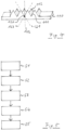
- figure 3 shows an exemplary representation in which several recordings of the calibration object in the sensor plane S are shown.
- a parameter is first determined for each individual recording.
- these are the reversal points or corner points of the profile.
- an adaptive split-and-merge algorithm can be used in combination with a hierarchical cluster method.
- the course of the profile can be approximated as well as possible by an alternating series of adapted lines.
- the points of intersection of these lines represent the parameters of the profile. If, for example, it is not possible to approximate a profile due to an incorrect measurement, it can be automatically discarded. After extraction of the reversal or corner points, the recording is no longer required.
- the relative relationships of the corner points of all recordings of the calibration object at the respective positions on the sensor are also assigned to the calibration profile according to a relative relationship between the corresponding corner points.
- the deviations of all matches are preferably minimized at the same time.
- mapping P is fully described by the mononomial coefficients a and b.
- Degrees other than 4 for the polynomial mapping P are, of course, also possible.
- a suitable optimization can be used to determine the mononomial coefficients for optimal imaging.
- the result of such an optimization is not just a single image, but an infinite number, which only differ in the concrete parameterization of the parameters of the calibration object. Rotation and translation of the calibration object within the light plane leave the relative relationship between the parameters unchanged. On the other hand, location-dependent changes between corresponding parameters on the sensor level, which are caused by perspective and lens distortion, are recorded.
- Any solution can be chosen from the solutions to the optimization task for determining the mononomial coefficients, since the individual solutions only differ in the choice of coordinates within the light plane.
- a calibration object that is expanded compared to a simple sawtooth pattern can be used.
- Such an extended calibration object 110 is, for example, shown schematically in figure 4 shown.
- the advanced calibration object differs from a simple sawtooth pattern in that it consists of multiple sawtooth patterns offset from one another.
- the calibration object 110 in figure 4 in plane 111 a first sawtooth pattern, and in plane 112 a further sawtooth pattern offset thereto.
- a corner point 120 is characterized, for example, by the lines 121, 122 and 123 running towards this corner point.
- this calibration object 110 With an ideal positioning of such an extended calibration object 110, ie parallel to the plane of light, this calibration object 110 likewise generates a symmetrical sawtooth profile. However, tilting or twisting of the calibration object 110 in the light plane results in the distances between adjacent saw teeth changing relative to one another in such a way that the twisting or tilting can also be closed together with the known characteristic lines.
- FIG. 1 shows a schematic representation of a flowchart on which a method for calibrating an optical measuring system 1 according to one embodiment is based.
- the method can carry out all the steps that have already been described above in connection with the optical measuring system.
- the previously described can also be analogous optical measurement system perform any of the steps described below in connection with the calibration procedure.
- the method for calibrating the optical measuring system 1 can be applied in particular to a previously described measuring system 1 with a light source 10 , an optical system 20 and a sensor 30 .
- a calibration object 110 is illuminated by the light source 10 in a light plane.
- step S2 several recordings of the illuminated calibration object 110 can be captured by the sensor 30.
- the sensor 30 is located in a sensor plane.
- step S3 corner points of the calibration object 110 are detected in the recordings. The detected corner points are then assigned to corresponding predetermined positions on the calibration object 110 in step S4.
- step S5 a mapping P from the light plane to the sensor plane is determined using the detected corner points and the corresponding positions on the calibration object 110.
- the corner points can be detected in particular by detecting edges in the recordings of the calibration object and determining the intersection points of the detected edges.
- the detected corner points can be assigned to corresponding positions on the calibration object using relative relationships of the corner points to one another and the relative relationships of the predetermined positions on the calibration object.
- the recordings of the illuminated calibration object can in particular include recordings in which the calibration object different spatial positions and/or with different spatial orientations.
- the calibration object can be moved across the entire light plane.
- 50 recordings of the calibration object within the area to be calibrated are possible for the calibration process.
- the calibration object can be moved automatically by means of a suitable device, which moves the calibration object over the area of the light plane.
- the movement is simply carried out by a user who manually moves the calibration object within the light plane. If necessary, the user can be guided by means of suitable optical or acoustic outputs to move the calibration object in a suitable manner across the light plane.
- the present invention relates to the calibration of an optical measurement system.
- the measurement system is calibrated in a single step, which takes into account both linear and non-linear parts of the relationship between the light plane and the sensor plane.
- the calibration process takes place using a single calibration object, which is moved through the light plane in any way during the calibration process.
- the measuring system can be calibrated in a simple and efficient manner.
Landscapes
- Physics & Mathematics (AREA)
- General Physics & Mathematics (AREA)
- Measurement Of Optical Distance (AREA)
- Length Measuring Devices By Optical Means (AREA)
Claims (12)
- Procédé destiné à étalonner un système de mesure optique (1), dans lequel le système de mesure (1) comprend une source lumineuse (10), une optique (20) et un capteur (30), comportant les étapes suivantes :- éclairage (S1) d'un objet d'étalonnage (110) dans un plan lumineux à l'aide de la source lumineuse (10) ;- enregistrement (S2) de plusieurs images de l'objet d'étalonnage éclairé (110) à l'aide du capteur (10) dans un plan de capteur, dans lequel l'objet d'étalonnage (110) est déplacé librement par un utilisateur dans une plage de mesure pendant l'enregistrement des plusieurs images ;- détection (S3) de points clés dans les images de l'objet d'étalonnage ;- association (S4) des points clés détectés à des positions prédéfinies correspondantes au niveau de l'objet d'étalonnage ; et- détermination (S5) d'une reproduction du plan de capteur dans le plan lumineux en utilisant les points clés détectés et les positions correspondantes au niveau de l'objet d'étalonnage,dans lequel la reproduction déterminée comprend une combinaison d'une reproduction linéaire et d'une reproduction non-linéaire, qui est déterminée dans une seule opération de calcul commune,dans lequel la reproduction est déterminée en utilisant plusieurs images d'un seul objet d'étalonnage (110) uniquement.
- Procédé selon la revendication 1, dans lequel la détection (S3) des points clés comprend une détection de bords dans les images de l'objet d'étalonnage et une définition de points d'intersection des bords détectés.
- Procédé selon la revendication 1 ou 2, dans lequel l'association (S4) des points clés détectés aux positions correspondantes au niveau de l'objet d'étalonnage (110) s'effectue en utilisant des relations relatives des points clés détectés les uns par rapport aux autres et des relations relatives des positions prédéfinies au niveau de l'objet d'étalonnage (110).
- Procédé selon une des revendications 1 à 3, dans lequel l'enregistrement (S2) des images de l'objet d'étalonnage éclairé s'effectue avec l'objet d'étalonnage (110) au niveau de plusieurs positions spatiales différentes et/ou avec des orientations spatiales différentes de l'objet d'étalonnage (110).
- Procédé selon la revendication 4, dans lequel les positions spatiales s'étendent sur l'étendue du plan lumineux à étalonner.
- Procédé selon une des revendications 1 à 5, comportant une étape destinée à émettre des instructions de positionnement de l'objet d'étalonnage (110).
- Procédé selon une des revendications 1 à 6, dans lequel la reproduction comprend une reproduction de polynôme avec un degré prédéfini.
- Système de mesure optique (1), comportant :une source lumineuse (10), qui est conçue pour éclairer un objet dans un plan lumineux ;un capteur (30), qui est conçu pour enregistrer la lumière du plan lumineux dans un plan de capteur ;une optique (20), qui est disposée entre le capteur (30) et le plan lumineux et qui est conçue pour focaliser la lumière du plan lumineux sur le plan de capteur ; etun moyen de traitement (40), qui est conçu pour enregistrer dans une opération d'étalonnage des données de capteur de plusieurs images du capteur (30) d'un objet d'étalonnage (110) pendant que l'objet d'étalonnage (110) est déplacé librement par un utilisateur dans une plage de mesure, pour détecter des points clés dans les images de l'objet d'étalonnage, pour associer les points clés détectés à des positions prédéfinies correspondantes au niveau de l'objet d'étalonnage (110) et pour déterminer une reproduction du plan de capteur dans le plan lumineux en utilisant les points clés détectés et les positions correspondantes au niveau de l'objet d'étalonnage (110),dans lequel le moyen de traitement (40) est en outre conçu pour réaliser l'opération d'étalonnage en utilisant plusieurs images d'un seul objet d'étalonnage (110), etdans lequel le moyen de traitement (40) est conçu pour déterminer une combinaison d'une reproduction linéaire et d'une reproduction non-linéaire dans une seule opération de calcul commune pour la reproduction déterminée.
- Système de mesure optique selon la revendication 8, comportant une mémoire qui est conçue pour fournir des données caractéristiques d'au moins un objet d'étalonnage (110) .
- Système de mesure optique (1) selon la revendication 8 ou 9, dans lequel le moyen de traitement (40) est conçu pour traiter une image d'un objet en utilisant la reproduction déterminée dans l'opération d'étalonnage.
- Système de mesure optique (1) selon une des revendications 8 à 10, comportant un objet d'étalonnage (110) pour le système de mesure optique (1), dans lequel l'objet d'étalonnage (21) présente une structure en dents de scie.
- Système de mesure optique (1) selon la revendication 11, dans lequel l'objet d'étalonnage (110) présente plusieurs structures en dents de scie décalées les unes par rapport aux autres.
Priority Applications (1)
| Application Number | Priority Date | Filing Date | Title |
|---|---|---|---|
| EP19200257.4A EP3798570B1 (fr) | 2019-09-27 | 2019-09-27 | Procédé d'étalonnage d'un système de mesure optique, système de mesure optique et objet d'étalonnage pour un système de mesure optique |
Applications Claiming Priority (1)
| Application Number | Priority Date | Filing Date | Title |
|---|---|---|---|
| EP19200257.4A EP3798570B1 (fr) | 2019-09-27 | 2019-09-27 | Procédé d'étalonnage d'un système de mesure optique, système de mesure optique et objet d'étalonnage pour un système de mesure optique |
Publications (2)
| Publication Number | Publication Date |
|---|---|
| EP3798570A1 EP3798570A1 (fr) | 2021-03-31 |
| EP3798570B1 true EP3798570B1 (fr) | 2023-06-28 |
Family
ID=68084690
Family Applications (1)
| Application Number | Title | Priority Date | Filing Date |
|---|---|---|---|
| EP19200257.4A Active EP3798570B1 (fr) | 2019-09-27 | 2019-09-27 | Procédé d'étalonnage d'un système de mesure optique, système de mesure optique et objet d'étalonnage pour un système de mesure optique |
Country Status (1)
| Country | Link |
|---|---|
| EP (1) | EP3798570B1 (fr) |
Family Cites Families (4)
| Publication number | Priority date | Publication date | Assignee | Title |
|---|---|---|---|---|
| JP2623367B2 (ja) * | 1990-11-05 | 1997-06-25 | 株式会社ユニスン | 三次元形状測定装置の校正方法 |
| DE602008004330D1 (de) * | 2008-07-04 | 2011-02-17 | Sick Ivp Aktiebolag | Kalibrierung eines Profilmesssystems |
| US10008007B2 (en) * | 2012-09-20 | 2018-06-26 | Brown University | Method for generating an array of 3-D points |
| CN107218904B (zh) * | 2017-07-14 | 2020-03-17 | 北京航空航天大学 | 一种基于锯齿靶标的线结构光视觉传感器标定方法 |
-
2019
- 2019-09-27 EP EP19200257.4A patent/EP3798570B1/fr active Active
Also Published As
| Publication number | Publication date |
|---|---|
| EP3798570A1 (fr) | 2021-03-31 |
Similar Documents
| Publication | Publication Date | Title |
|---|---|---|
| EP2040026B1 (fr) | Procédé et système de calibrage d'un appareil de mesure de la forme d'une surface réfléchissante | |
| DE69826753T2 (de) | Optischer Profilsensor | |
| DE10081029B4 (de) | Bildbearbeitung zur Vorbereitung einer Texturnalyse | |
| AT506110B1 (de) | Vorrichtung und verfahren zur erfassung von körpermassdaten und konturdaten | |
| DE102015116047B4 (de) | Prüfvorrichtung und Steuerverfahren für eine Prüfvorrichtung | |
| EP1711777B1 (fr) | Procede pour determiner la position et le mouvement relativ d'un objet dans un espace | |
| DE102017215334A1 (de) | Verfahren, Computerprogrammprodukt und Messsystem zum Betrieb mindestens eines Triangulations-Laserscanners zur Identifizierung von Oberflächeneigenschaften eines zu vermessenden Werkstücks | |
| DE19623172C1 (de) | Verfahren zur dreidimensionalen optischen Vermessung von Objektoberflächen | |
| DE102006049695A1 (de) | Vorrichtung und Verfahren zum berührungslosen Erfassen einer dreidimensionalen Kontur | |
| DE102006055758B4 (de) | Verfahren zur Kalibrierung von Kameras und Projektoren | |
| EP0507923A1 (fr) | Procede et dispositif pour le mesurage opto-electronique d'objets | |
| DE4212404B4 (de) | Vorrichtung und Verfahren zur Bestimmung der räumlichen Form eines langgestreckten Bauteils | |
| DE10127304C5 (de) | Verfahren und Vorrichtung zur Bestimmung der dreidimensionalen Kontur einer spiegelnden Oberfläche eines Objektes | |
| DE10328523B4 (de) | Verfahren und Meßvorrichtung zur berührungslosen Vermessung einer Kontur einer Oberfläche | |
| DE19902401C2 (de) | Verfahren und Vorrichtung zur Bestimmung der Geometrie von blattförmigem Gut oder Stapeln davon | |
| EP1284409A1 (fr) | Procédé et appareil pour l'inspection de la déformation d'objets | |
| DE102004058655B4 (de) | Verfahren und Anordnung zum Messen von Geometrien eines Objektes mittels eines Koordinatenmessgerätes | |
| WO2009018894A1 (fr) | Procédé et dispositif de détermination de données géométriques d'un objet mesuré | |
| DE19953063A1 (de) | Verfahren zur dreidimensionalen optischen Vermessung von Objektoberflächen | |
| EP3628995A1 (fr) | Modèle d'étalonnage et procédé d'étalonnage destinés à l'étalonnage géométrique d'une pluralité de caméras d'un réseau de caméra | |
| EP3798570B1 (fr) | Procédé d'étalonnage d'un système de mesure optique, système de mesure optique et objet d'étalonnage pour un système de mesure optique | |
| EP2972071A1 (fr) | Dispositif de mesure d'un objet carcasse d'animal de boucherie | |
| EP2191229B1 (fr) | Procédé pour déterminer une arête d'un objet sur lequel doit être réalisée une mesure optique et appareil de mesure de coordonnées | |
| DE102006006876A1 (de) | Verfahren und Vorrichtung zum Erfassen einer Kontur einer reflektierenden Oberfläche | |
| DE102005043753A1 (de) | Verfahren zur Bestimmung der Raumkoordinaten von Oberflächenpunkten eines Prüflings und Vorrichtung zur Durchführung des Verfahrens |
Legal Events
| Date | Code | Title | Description |
|---|---|---|---|
| PUAI | Public reference made under article 153(3) epc to a published international application that has entered the european phase |
Free format text: ORIGINAL CODE: 0009012 |
|
| STAA | Information on the status of an ep patent application or granted ep patent |
Free format text: STATUS: THE APPLICATION HAS BEEN PUBLISHED |
|
| AK | Designated contracting states |
Kind code of ref document: A1 Designated state(s): AL AT BE BG CH CY CZ DE DK EE ES FI FR GB GR HR HU IE IS IT LI LT LU LV MC MK MT NL NO PL PT RO RS SE SI SK SM TR |
|
| AX | Request for extension of the european patent |
Extension state: BA ME |
|
| STAA | Information on the status of an ep patent application or granted ep patent |
Free format text: STATUS: REQUEST FOR EXAMINATION WAS MADE |
|
| 17P | Request for examination filed |
Effective date: 20210914 |
|
| RBV | Designated contracting states (corrected) |
Designated state(s): AL AT BE BG CH CY CZ DE DK EE ES FI FR GB GR HR HU IE IS IT LI LT LU LV MC MK MT NL NO PL PT RO RS SE SI SK SM TR |
|
| GRAP | Despatch of communication of intention to grant a patent |
Free format text: ORIGINAL CODE: EPIDOSNIGR1 |
|
| STAA | Information on the status of an ep patent application or granted ep patent |
Free format text: STATUS: GRANT OF PATENT IS INTENDED |
|
| RIC1 | Information provided on ipc code assigned before grant |
Ipc: G01B 11/25 20060101ALN20230201BHEP Ipc: G01B 21/04 20060101AFI20230201BHEP |
|
| INTG | Intention to grant announced |
Effective date: 20230221 |
|
| GRAS | Grant fee paid |
Free format text: ORIGINAL CODE: EPIDOSNIGR3 |
|
| GRAA | (expected) grant |
Free format text: ORIGINAL CODE: 0009210 |
|
| STAA | Information on the status of an ep patent application or granted ep patent |
Free format text: STATUS: THE PATENT HAS BEEN GRANTED |
|
| AK | Designated contracting states |
Kind code of ref document: B1 Designated state(s): AL AT BE BG CH CY CZ DE DK EE ES FI FR GB GR HR HU IE IS IT LI LT LU LV MC MK MT NL NO PL PT RO RS SE SI SK SM TR |
|
| REG | Reference to a national code |
Ref country code: CH Ref legal event code: EP |
|
| REG | Reference to a national code |
Ref country code: AT Ref legal event code: REF Ref document number: 1583052 Country of ref document: AT Kind code of ref document: T Effective date: 20230715 |
|
| REG | Reference to a national code |
Ref country code: IE Ref legal event code: FG4D Free format text: LANGUAGE OF EP DOCUMENT: GERMAN |
|
| REG | Reference to a national code |
Ref country code: DE Ref legal event code: R096 Ref document number: 502019008312 Country of ref document: DE |
|
| REG | Reference to a national code |
Ref country code: LT Ref legal event code: MG9D |
|
| PG25 | Lapsed in a contracting state [announced via postgrant information from national office to epo] |
Ref country code: SE Free format text: LAPSE BECAUSE OF FAILURE TO SUBMIT A TRANSLATION OF THE DESCRIPTION OR TO PAY THE FEE WITHIN THE PRESCRIBED TIME-LIMIT Effective date: 20230628 Ref country code: NO Free format text: LAPSE BECAUSE OF FAILURE TO SUBMIT A TRANSLATION OF THE DESCRIPTION OR TO PAY THE FEE WITHIN THE PRESCRIBED TIME-LIMIT Effective date: 20230928 |
|
| REG | Reference to a national code |
Ref country code: NL Ref legal event code: MP Effective date: 20230628 |
|
| PG25 | Lapsed in a contracting state [announced via postgrant information from national office to epo] |
Ref country code: RS Free format text: LAPSE BECAUSE OF FAILURE TO SUBMIT A TRANSLATION OF THE DESCRIPTION OR TO PAY THE FEE WITHIN THE PRESCRIBED TIME-LIMIT Effective date: 20230628 Ref country code: NL Free format text: LAPSE BECAUSE OF FAILURE TO SUBMIT A TRANSLATION OF THE DESCRIPTION OR TO PAY THE FEE WITHIN THE PRESCRIBED TIME-LIMIT Effective date: 20230628 Ref country code: LV Free format text: LAPSE BECAUSE OF FAILURE TO SUBMIT A TRANSLATION OF THE DESCRIPTION OR TO PAY THE FEE WITHIN THE PRESCRIBED TIME-LIMIT Effective date: 20230628 Ref country code: LT Free format text: LAPSE BECAUSE OF FAILURE TO SUBMIT A TRANSLATION OF THE DESCRIPTION OR TO PAY THE FEE WITHIN THE PRESCRIBED TIME-LIMIT Effective date: 20230628 Ref country code: HR Free format text: LAPSE BECAUSE OF FAILURE TO SUBMIT A TRANSLATION OF THE DESCRIPTION OR TO PAY THE FEE WITHIN THE PRESCRIBED TIME-LIMIT Effective date: 20230628 Ref country code: GR Free format text: LAPSE BECAUSE OF FAILURE TO SUBMIT A TRANSLATION OF THE DESCRIPTION OR TO PAY THE FEE WITHIN THE PRESCRIBED TIME-LIMIT Effective date: 20230929 |
|
| PG25 | Lapsed in a contracting state [announced via postgrant information from national office to epo] |
Ref country code: FI Free format text: LAPSE BECAUSE OF FAILURE TO SUBMIT A TRANSLATION OF THE DESCRIPTION OR TO PAY THE FEE WITHIN THE PRESCRIBED TIME-LIMIT Effective date: 20230628 |
|
| PG25 | Lapsed in a contracting state [announced via postgrant information from national office to epo] |
Ref country code: SK Free format text: LAPSE BECAUSE OF FAILURE TO SUBMIT A TRANSLATION OF THE DESCRIPTION OR TO PAY THE FEE WITHIN THE PRESCRIBED TIME-LIMIT Effective date: 20230628 |
|
| PG25 | Lapsed in a contracting state [announced via postgrant information from national office to epo] |
Ref country code: ES Free format text: LAPSE BECAUSE OF FAILURE TO SUBMIT A TRANSLATION OF THE DESCRIPTION OR TO PAY THE FEE WITHIN THE PRESCRIBED TIME-LIMIT Effective date: 20230628 |
|
| PG25 | Lapsed in a contracting state [announced via postgrant information from national office to epo] |
Ref country code: IS Free format text: LAPSE BECAUSE OF FAILURE TO SUBMIT A TRANSLATION OF THE DESCRIPTION OR TO PAY THE FEE WITHIN THE PRESCRIBED TIME-LIMIT Effective date: 20231028 |
|
| PG25 | Lapsed in a contracting state [announced via postgrant information from national office to epo] |
Ref country code: SM Free format text: LAPSE BECAUSE OF FAILURE TO SUBMIT A TRANSLATION OF THE DESCRIPTION OR TO PAY THE FEE WITHIN THE PRESCRIBED TIME-LIMIT Effective date: 20230628 Ref country code: SK Free format text: LAPSE BECAUSE OF FAILURE TO SUBMIT A TRANSLATION OF THE DESCRIPTION OR TO PAY THE FEE WITHIN THE PRESCRIBED TIME-LIMIT Effective date: 20230628 Ref country code: RO Free format text: LAPSE BECAUSE OF FAILURE TO SUBMIT A TRANSLATION OF THE DESCRIPTION OR TO PAY THE FEE WITHIN THE PRESCRIBED TIME-LIMIT Effective date: 20230628 Ref country code: PT Free format text: LAPSE BECAUSE OF FAILURE TO SUBMIT A TRANSLATION OF THE DESCRIPTION OR TO PAY THE FEE WITHIN THE PRESCRIBED TIME-LIMIT Effective date: 20231030 Ref country code: IS Free format text: LAPSE BECAUSE OF FAILURE TO SUBMIT A TRANSLATION OF THE DESCRIPTION OR TO PAY THE FEE WITHIN THE PRESCRIBED TIME-LIMIT Effective date: 20231028 Ref country code: ES Free format text: LAPSE BECAUSE OF FAILURE TO SUBMIT A TRANSLATION OF THE DESCRIPTION OR TO PAY THE FEE WITHIN THE PRESCRIBED TIME-LIMIT Effective date: 20230628 Ref country code: EE Free format text: LAPSE BECAUSE OF FAILURE TO SUBMIT A TRANSLATION OF THE DESCRIPTION OR TO PAY THE FEE WITHIN THE PRESCRIBED TIME-LIMIT Effective date: 20230628 Ref country code: CZ Free format text: LAPSE BECAUSE OF FAILURE TO SUBMIT A TRANSLATION OF THE DESCRIPTION OR TO PAY THE FEE WITHIN THE PRESCRIBED TIME-LIMIT Effective date: 20230628 |
|
| PG25 | Lapsed in a contracting state [announced via postgrant information from national office to epo] |
Ref country code: PL Free format text: LAPSE BECAUSE OF FAILURE TO SUBMIT A TRANSLATION OF THE DESCRIPTION OR TO PAY THE FEE WITHIN THE PRESCRIBED TIME-LIMIT Effective date: 20230628 |
|
| REG | Reference to a national code |
Ref country code: DE Ref legal event code: R097 Ref document number: 502019008312 Country of ref document: DE |
|
| PG25 | Lapsed in a contracting state [announced via postgrant information from national office to epo] |
Ref country code: DK Free format text: LAPSE BECAUSE OF FAILURE TO SUBMIT A TRANSLATION OF THE DESCRIPTION OR TO PAY THE FEE WITHIN THE PRESCRIBED TIME-LIMIT Effective date: 20230628 |
|
| REG | Reference to a national code |
Ref country code: CH Ref legal event code: PL |
|
| PLBE | No opposition filed within time limit |
Free format text: ORIGINAL CODE: 0009261 |
|
| STAA | Information on the status of an ep patent application or granted ep patent |
Free format text: STATUS: NO OPPOSITION FILED WITHIN TIME LIMIT |
|
| PG25 | Lapsed in a contracting state [announced via postgrant information from national office to epo] |
Ref country code: LU Free format text: LAPSE BECAUSE OF NON-PAYMENT OF DUE FEES Effective date: 20230927 |
|
| REG | Reference to a national code |
Ref country code: BE Ref legal event code: MM Effective date: 20230930 |
|
| PG25 | Lapsed in a contracting state [announced via postgrant information from national office to epo] |
Ref country code: LU Free format text: LAPSE BECAUSE OF NON-PAYMENT OF DUE FEES Effective date: 20230927 Ref country code: IT Free format text: LAPSE BECAUSE OF FAILURE TO SUBMIT A TRANSLATION OF THE DESCRIPTION OR TO PAY THE FEE WITHIN THE PRESCRIBED TIME-LIMIT Effective date: 20230628 Ref country code: MC Free format text: LAPSE BECAUSE OF FAILURE TO SUBMIT A TRANSLATION OF THE DESCRIPTION OR TO PAY THE FEE WITHIN THE PRESCRIBED TIME-LIMIT Effective date: 20230628 |
|
| 26N | No opposition filed |
Effective date: 20240402 |
|
| REG | Reference to a national code |
Ref country code: IE Ref legal event code: MM4A |
|
| PG25 | Lapsed in a contracting state [announced via postgrant information from national office to epo] |
Ref country code: IE Free format text: LAPSE BECAUSE OF NON-PAYMENT OF DUE FEES Effective date: 20230927 |
|
| PG25 | Lapsed in a contracting state [announced via postgrant information from national office to epo] |
Ref country code: CH Free format text: LAPSE BECAUSE OF NON-PAYMENT OF DUE FEES Effective date: 20230930 |
|
| PG25 | Lapsed in a contracting state [announced via postgrant information from national office to epo] |
Ref country code: IE Free format text: LAPSE BECAUSE OF NON-PAYMENT OF DUE FEES Effective date: 20230927 Ref country code: CH Free format text: LAPSE BECAUSE OF NON-PAYMENT OF DUE FEES Effective date: 20230930 Ref country code: SI Free format text: LAPSE BECAUSE OF FAILURE TO SUBMIT A TRANSLATION OF THE DESCRIPTION OR TO PAY THE FEE WITHIN THE PRESCRIBED TIME-LIMIT Effective date: 20230628 |
|
| PG25 | Lapsed in a contracting state [announced via postgrant information from national office to epo] |
Ref country code: BE Free format text: LAPSE BECAUSE OF NON-PAYMENT OF DUE FEES Effective date: 20230930 |
|
| PG25 | Lapsed in a contracting state [announced via postgrant information from national office to epo] |
Ref country code: BG Free format text: LAPSE BECAUSE OF FAILURE TO SUBMIT A TRANSLATION OF THE DESCRIPTION OR TO PAY THE FEE WITHIN THE PRESCRIBED TIME-LIMIT Effective date: 20230628 |
|
| PG25 | Lapsed in a contracting state [announced via postgrant information from national office to epo] |
Ref country code: BG Free format text: LAPSE BECAUSE OF FAILURE TO SUBMIT A TRANSLATION OF THE DESCRIPTION OR TO PAY THE FEE WITHIN THE PRESCRIBED TIME-LIMIT Effective date: 20230628 |
|
| PG25 | Lapsed in a contracting state [announced via postgrant information from national office to epo] |
Ref country code: CY Free format text: LAPSE BECAUSE OF FAILURE TO SUBMIT A TRANSLATION OF THE DESCRIPTION OR TO PAY THE FEE WITHIN THE PRESCRIBED TIME-LIMIT; INVALID AB INITIO Effective date: 20190927 |
|
| PG25 | Lapsed in a contracting state [announced via postgrant information from national office to epo] |
Ref country code: HU Free format text: LAPSE BECAUSE OF FAILURE TO SUBMIT A TRANSLATION OF THE DESCRIPTION OR TO PAY THE FEE WITHIN THE PRESCRIBED TIME-LIMIT; INVALID AB INITIO Effective date: 20190927 |
|
| PGFP | Annual fee paid to national office [announced via postgrant information from national office to epo] |
Ref country code: GB Payment date: 20250919 Year of fee payment: 7 |
|
| PGFP | Annual fee paid to national office [announced via postgrant information from national office to epo] |
Ref country code: FR Payment date: 20250922 Year of fee payment: 7 |
|
| REG | Reference to a national code |
Ref country code: AT Ref legal event code: MM01 Ref document number: 1583052 Country of ref document: AT Kind code of ref document: T Effective date: 20240927 |
|
| PG25 | Lapsed in a contracting state [announced via postgrant information from national office to epo] |
Ref country code: TR Free format text: LAPSE BECAUSE OF FAILURE TO SUBMIT A TRANSLATION OF THE DESCRIPTION OR TO PAY THE FEE WITHIN THE PRESCRIBED TIME-LIMIT Effective date: 20230628 |
|
| PGFP | Annual fee paid to national office [announced via postgrant information from national office to epo] |
Ref country code: DE Payment date: 20250930 Year of fee payment: 7 |
|
| PG25 | Lapsed in a contracting state [announced via postgrant information from national office to epo] |
Ref country code: AT Free format text: LAPSE BECAUSE OF NON-PAYMENT OF DUE FEES Effective date: 20240927 |
|
| PGFP | Annual fee paid to national office [announced via postgrant information from national office to epo] |
Ref country code: AT Payment date: 20260410 Year of fee payment: 5 |
|
| REG | Reference to a national code |
Ref country code: DE Ref legal event code: R081 Ref document number: 502019008312 Country of ref document: DE Owner name: STEMMER IMAGING AG, DE Free format text: FORMER OWNER: STEMMER IMAGING AG, 82178 PUCHHEIM, DE |