EP2351060B1 - Vakuumschalter mit beidseitig fest verschienten anschlussklemmen - Google Patents
Vakuumschalter mit beidseitig fest verschienten anschlussklemmen Download PDFInfo
- Publication number
- EP2351060B1 EP2351060B1 EP09752343.5A EP09752343A EP2351060B1 EP 2351060 B1 EP2351060 B1 EP 2351060B1 EP 09752343 A EP09752343 A EP 09752343A EP 2351060 B1 EP2351060 B1 EP 2351060B1
- Authority
- EP
- European Patent Office
- Prior art keywords
- contact
- contact piece
- vacuum switch
- vacuum
- moving
- Prior art date
- Legal status (The legal status is an assumption and is not a legal conclusion. Google has not performed a legal analysis and makes no representation as to the accuracy of the status listed.)
- Active
Links
Images
Classifications
-
- H—ELECTRICITY
- H01—ELECTRIC ELEMENTS
- H01H—ELECTRIC SWITCHES; RELAYS; SELECTORS; EMERGENCY PROTECTIVE DEVICES
- H01H33/00—High-tension or heavy-current switches with arc-extinguishing or arc-preventing means
- H01H33/60—Switches wherein the means for extinguishing or preventing the arc do not include separate means for obtaining or increasing flow of arc-extinguishing fluid
- H01H33/66—Vacuum switches
-
- H—ELECTRICITY
- H01—ELECTRIC ELEMENTS
- H01H—ELECTRIC SWITCHES; RELAYS; SELECTORS; EMERGENCY PROTECTIVE DEVICES
- H01H33/00—High-tension or heavy-current switches with arc-extinguishing or arc-preventing means
- H01H33/60—Switches wherein the means for extinguishing or preventing the arc do not include separate means for obtaining or increasing flow of arc-extinguishing fluid
- H01H33/66—Vacuum switches
- H01H33/6606—Terminal arrangements
-
- H—ELECTRICITY
- H01—ELECTRIC ELEMENTS
- H01H—ELECTRIC SWITCHES; RELAYS; SELECTORS; EMERGENCY PROTECTIVE DEVICES
- H01H1/00—Contacts
- H01H1/58—Electric connections to or between contacts; Terminals
-
- H—ELECTRICITY
- H01—ELECTRIC ELEMENTS
- H01H—ELECTRIC SWITCHES; RELAYS; SELECTORS; EMERGENCY PROTECTIVE DEVICES
- H01H1/00—Contacts
- H01H1/58—Electric connections to or between contacts; Terminals
- H01H1/5833—Electric connections to or between contacts; Terminals comprising an articulating, sliding or rolling contact between movable contact and terminal
-
- H—ELECTRICITY
- H01—ELECTRIC ELEMENTS
- H01H—ELECTRIC SWITCHES; RELAYS; SELECTORS; EMERGENCY PROTECTIVE DEVICES
- H01H39/00—Switching devices actuated by an explosion produced within the device and initiated by an electric current
- H01H39/004—Closing switches
-
- H—ELECTRICITY
- H01—ELECTRIC ELEMENTS
- H01H—ELECTRIC SWITCHES; RELAYS; SELECTORS; EMERGENCY PROTECTIVE DEVICES
- H01H79/00—Protective switches in which excess current causes the closing of contacts, e.g. for short-circuiting the apparatus to be protected
Definitions
- the invention relates to a vacuum switch with a vacuum chamber, in which a vacuum prevails and in which a switching contact is arranged, wherein the switching contact fixedly connected to the vacuum chamber fixed contact, which is in electrical contact with a fixed contact terminal, and with respect to the fixed contact piece movably guided BewegCount founded which is arranged in a disconnected position at a distance from the fixed contact piece and contacts the fixed contact piece in a contact position, a drive unit for generating a drive movement, a switching mechanism connected to the drive unit and the moving contact piece, which has an electrically conductive conductor section extending up to the moving contact piece, and connecting means which electrically connect a BewegWalletan gleichklemme in the contact position with the BewegCount Federation.
- Such a vacuum switch is out of the US 4,684,771 already known.
- the disclosed therein vacuum switch has a vacuum interrupter with a fixed contact and a moving contact, which face each other frontally in a switching direction.
- the switching movement is generated by an unspecified drive unit and introduced by means of a mechanical arrangement, which is not further explained, in a shift rod, which extends with its one end into the vacuum interrupter chamber inside.
- the shift rod via a pivot lever is electrically conductive and movable in the switching direction flexibly connected to a Bewegjoran gleichklemme.
- the swivel lever is centered in a housing hinged and has two hinged together pivot lever arms. The pivot lever arms are clamped on one side with the shift rod and on the other side with the Bewegromean gleichklemme. To generate the necessary clamping force is an appropriate spring.
- When switching the pivot lever is pivoted about the stationary suspension.
- Vacuum switches are used in particular in the medium voltage, ie in a voltage range between 1kV and 52kV. Also in this voltage range occur in particular when switching high power arcs, which are drawn when disconnecting the switch contacts. To extinguish these arcs in a current zero crossing, the switching contacts are arranged in a vacuum chamber in which a vacuum prevails.
- a fixed contact permanently connected to the vacuum chamber and a movable contact guided in this respect are generally provided.
- the moving contact can be both as a pivoting switch blade but also be designed as a lifting contact, which is opposite to the fixed contact in a longitudinal direction and is movably guided in this longitudinal direction.
- a bellows made of metal which is connected on the one hand with the vacuum chamber and on the other hand with the moving contact piece.
- the drive movement of the vacuum switch is generated by a drive unit, which is realized for example as a spring-loaded drive or as a magnetic drive.
- the drive movement generated by the drive unit is introduced via a switching mechanism in the BewegCount scholar.
- the switching mechanism comprises said shift rod having a conductive portion extending toward the moving contact.
- a Beweg Membershipan gleichklemme connecting means are provided, which are realized according to the prior art as a sliding contact, tape contact or roller contact.
- a ribbon contact which has a flexible electrically conductive band portion to allow movement of the shift rod.
- the current flows from the fixed contact terminal via the fixed contact piece, the moving contact piece, the electrically conductive portion of the switching rod and the flexible connecting means to the Bewegumblean gleichklemme.
- the flexible connecting means has the disadvantage that they have a reduced current carrying capacity compared to the remaining components of the current path, so that, in particular at high short-circuit currents, a high resistance that is no longer acceptable for many applications occurs.
- a complex connection technique is required for the flexible connection means, since it leads to high friction during fast switching. or bending forces comes.
- flexible connection means are expansive.
- Cone-shaped contacts are also known from the prior art. Cone contacts are used according to the prior art in switches with two contact arrangements. For example, when the switch is turned on, the cone contact closes first, resulting in the expected arc at the cone contact. The second contact arrangement follows the first closing contact arrangement, so that it can be closed without arcing. Because of their better conductivity, when both contacts are closed, the current flows across the lagging second contact arrangement. However, damage to the second contact arrangement as a result of the arc is avoided.
- the object of the invention is to provide a vacuum switch of the type mentioned, which is compact and low in complexity and provides a safe current path with a high current carrying capacity between the terminals of the vacuum switch especially at high turn-on.
- the invention solves this problem in that the connecting means have a terminal contact, which has a connected to the conductor portion of the switching mechanism Ein.g., Ein.g., Ein., Arch., aforementioned patent application, a Marlesky, a Marlesky, a Marlesky, a Marlesky, a Marlesky, a Marlesky, a Marlesky, a Marlesky, a Marlesky, a Marlesky, etc.
- a vacuum switch which has a clamping contact instead of the usual connecting means. Due to the terminal contact, it is possible to provide a vacuum switch with only solid busbar.
- the switching mechanism is therefore free of a flexible conductor section, rolling or sliding contacts that close the switch contact can cause mechanical problems when fast. According to the invention it is therefore possible to close the vacuum switch quickly.
- the vacuum switch is also compact and can be used without problems even in small installation spaces.
- the clamping contact has two contact pieces.
- the counter-clamping contact of the terminal contact is mechanically fixed to the Beweg.an gleichklemme and thus arranged stationary.
- the second contact piece of the clamping contact namely the Ein thoroughlyklemm toast, is fixedly mounted on the switching mechanism, wherein between the electrically conductive conductor portion and the Ein thoroughlyklemm toast fog an electrical connection is provided. In this way, the BewegCountgre is also electrically connected to the Ein thoroughlyklemmMessage juxtapos.
- the clamping contact leads the switch contact when closing the vacuum switch ahead of time. According to this advantageous further development, it is ensured that no arc arises outside the vacuum chamber.
- the Ein thoroughlyklemmtem Gi is so with the Switching mechanism connected so that when jamming the contacts of the terminal contact the BewegCount Gi is slowed down. The impact on the fixed contact piece is therefore less violent according to this expedient development of the invention.
- the drive unit is a pyrotechnic force element, wherein an ignition circuit is provided for triggering the pyrotechnic force element.
- Pyrotechnic power elements allow a particularly fast closing of the vacuum switch.
- high Einschalter be generated with a violent opening of the moving contact in the wake.
- the vacuum switch can therefore only be switched once and then has to be replaced.
- the pyrotechnic drive has a displacement element, which is displaced explosively by a distance as a result of triggering.
- the switching mechanism is realized as extending in a longitudinal direction and connected to the displacement element shift rod, wherein the displacement element is set up to trigger the pyrotechnic drive for holding the BewegCounts foundedes in its disconnected position.
- the switching contact is designed as a so-called HubCount. In other words, the moving contact is held at the end of a switching rod protruding into the vacuum chamber.
- the BewegCount commonly the fixed contact piece in the longitudinal direction opposite, in which also extends the shift rod.
- the pyrotechnic drive is located, wherein the shift rod is mechanically connected to the displacement element, which is for example designed pin-shaped and arranged in alignment with the shift rod.
- the pyrotechnic drive is oriented so that upon ignition of the pyrotechnic force element, the displacement element is displaced in the longitudinal direction to the fixed contact. Due to the rigid connection between the displacement element and moving contact piece by means of the switching rod, there is a shift of the moving contact piece in the direction of the fixed contact piece.
- the Ein thoroughlyklemmAuthMap founded is pressed into the counter-clamping contact, whereby the current path between the terminals of the vacuum switch is closed.
- the displacement element Before the ignition of the pyrotechnic force element, the displacement element provides a holding force that precludes the closing of the switching contact. Due to the pressure difference in the interior of the vacuum chamber and the outside atmosphere, a continuous closing force acts, which drives the moving contact piece onto the fixed contact piece. The opposite is the holding force of the displacement element.
- positioning means are provided for adjusting the spatial position of the displacement element and thus the distance of the BewegCount Symposiumes with respect to the fixed contact piece.
- positioning means are, for example, simple positioning screws, with which the position of the pyrotechnic drive unit and thus of the displacement element in a common holding frame is changeable.
- the clamping contact is a cone contact, which has a cone-shaped Einklemm.
- the Einklemm. is for example on the cylindrical switching rod attached ring which increases continuously against the switching movement in its circumference, so that in cross-section a wedge-shaped Einklemm.
- the Einklemm. is arranged loosely on the shift rod, wherein when switching on the switch results in a clamping fit of the Einklemm.
- Deviating from this, however, the Ein thoroughlyklemmfeature also be firmly connected to the shift rod, for example, by adhesive, welding, screwing or shrinking.
- the pinching contact piece is already loosely attached to the counter-clamping contact piece in the disconnected position. In this way it is ensured that the terminal contact leads the switch contact in any case in time.
- the fixed contact piece is held by a contact surface of a wall of the vacuum chamber contact rod, which is at least mechanically connected outside of the vacuum chamber with holding means for supporting the vacuum switch and at least electrically connected to contact means which are galvanically connected to the fixed contact terminal, wherein the holding means the contact means from the perspective of Fixed contact piece are connected downstream.
- the invention also relates to an inverter valve for converting an electrical current or an electrical voltage with a series circuit of bipolar submodules, each submodule comprising at least one energy store and a power semiconductor circuit with which the voltage dropping across the energy store or a zero voltage can be generated at the connection of the assigned submodule, and wherein each submodule is assigned bridging means for bridging the submodule in the event of a fault.
- Such converter valves have already become known under the term multi-level converter.
- such converter valves in the field of energy transmission and energy distribution are successfully applicable, so that there is an ever-increasing demand for such converter valves.
- failure of one of the submodules of the series connection it makes sense to bridge the submodule quickly, so that the operation of the converter valve with the remaining submodules can be continued.
- the object of the invention is therefore also to provide such a converter valve, which can be safely, reliably and quickly bridged.
- the invention solves this problem with bridging means comprising a vacuum switch according to the aforementioned type.
- the power semiconductor circuit for generating a voltage at the terminals of each submodule is expediently arranged so that the voltage dropping across the energy store is inverse.
- both the voltage drop across the energy store, for example a capacitor, and the voltage inverse thereto can be generated by the power semiconductor circuit.
- the prerequisite for this is that energy storage and power semiconductor switch form a so-called full bridge circuit, which can also be referred to as H-bridge.
- half-bridge circuits are also possible within the scope of the invention.
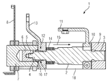
- the figure shows a cross-sectional view of an embodiment of the vacuum switch according to the invention 1.
- the vacuum switch 1 has a figured in the figure, not shown switching contact in a vacuum chamber 2.
- the vacuum interrupter chamber has a ceramic tube which extends between the contacts and acts as an insulator.
- In the vacuum chamber 2 projects into a fixed contact pin 3, which carries at its arranged in the vacuum chamber 2 end of the invisible fixed contact piece.
- In the longitudinal direction of the fixed contact piece is the BewegCount founded, which is supported by the free end of a shift rod 4, which forms the switching mechanism of the vacuum switch 1.
- the shift rod 6 is fixedly connected to a displacement element 6 of a pyrotechnic drive 7.
- Reference symbol 8 schematically illustrates the evaluation electronics of a control unit.
- a retaining strip 18 which extends between the pole heads and consists of an insulating material, for example of a glass fiber reinforced plastic.
- the vacuum chamber 2 and the fixed contact pin 3 via holding means 9 also stationary with respect to the support frame 8 is arranged.
- Contact means 10 continue to provide an electrical connection of the fixed contact pin 3 and thus the fixed contact piece with a fixed contact terminal 11th
- the shift rod 4 is formed continuously conductive in the embodiment shown.
- a clamping contact 12 is used for electrical connection of the shift rod 4 and thus the figured not BewegCount réellees with a permanently ver Kunststoff BewegTypean gleichklemme 13.
- the longitudinally movable and simultaneously vacuum-tight connection of the shift rod 4 with the vacuum chamber 2 is only schematically indicated metal bellows 14.
- the clamping contact 12 includes an Ein thoroughlyklemm toasting 16 and a complementary form complementary counter-clamping contact piece 17.
- the Ein Germanyklemmtitle securities 16 is provided conically, so that it is shown in the cross-sectional view shown as a wedge.
- the figuratively illustrated vacuum chamber 2 is used to bridge a submodule of an inverter valve, which has a series circuit of identically constructed bipolar submodules.
- a submodule fault high short-circuit currents occur in the submodule with arcing in the wake.
- the vacuum switch 1 is closed.
- first of all the short-circuit current is detected by sensors (not shown) in the submodule arranged parallel to the vacuum switch 1.
- the voltage can also be measured and supplied to said control unit.
- the control unit sends an ignition signal to the pyrotechnic force element 7. It comes to the explosive displacement of the displacement element 6 and thus the shift rod 4.
- the shift rod 4 in the direction of arrow 15, ie in the longitudinal direction, moved.
- there is also a firm jamming of the Ein IndustriesklemmWallet publishedes with the counter-clamping contact piece, wherein an electrical contact is provided. If the moving contact piece contacts the fixed contact piece, the current path between the fixed contact connection terminal 11 and the moving contact connection terminal 13 is closed.
Landscapes
- Physics & Mathematics (AREA)
- Electromagnetism (AREA)
- High-Tension Arc-Extinguishing Switches Without Spraying Means (AREA)
- Push-Button Switches (AREA)
Description
- Die Erfindung betrifft einen Vakuumschalter mit einer Vakuumkammer, in der ein Vakuum herrscht und in der ein Schaltkontakt angeordnet ist, wobei der Schaltkontakt ein fest mit der Vakuumkammer verbundenes Festkontaktstück, das in elektrischem Kontakt mit einer Festkontaktanschlussklemme ist, und ein bezüglich des Festkontaktstückes beweglich geführtes Bewegkontaktstück aufweist, das in einer Trennstellung mit Abstand zum Festkontaktstück angeordnet ist und in einer Kontaktstellung das Festkontaktstück kontaktiert, einer Antriebseinheit zum Erzeugen einer Antriebsbewegung, einer mit der Antriebseinheit und dem Bewegkontaktstück verbundenen Schaltmechanik, die einen sich bis zum Bewegkontaktstück hin erstreckenden elektrisch leitenden Leiterabschnitt aufweist, und Verbindungsmitteln, die in der Kontaktstellung eine Bewegkontaktanschlussklemme elektrisch mit dem Bewegkontaktstück verbinden.
- Ein solcher Vakuumschalter ist aus der
US 4,684,771 bereits bekannt. Der dort offenbarte Vakuumschalter weist eine Vakuumschaltröhre mit einem Festkontakt und einem Bewegkontakt auf, die sich in einer Schaltrichtung stirnseitig gegenüberliegen. Die Schaltbewegung wird von einer nicht weiter spezifizierten Antriebseinheit erzeugt und mittels einer mechanischen Anordnung, die nicht weiter erläutert ist, in eine Schaltstange eingeleitet, die sich mit ihrem einen Ende in die Vakuumschaltkammer hinein erstreckt. Außerhalb der Vakuumschaltkammer ist die Schaltstange über einen Schwenkhebel elektrisch leitend und in Schaltrichtung beweglich flexibel mit einer Bewegkontaktanschlussklemme verbunden. Der Schwenkhebel ist mittig in einem Gehäuse angelenkt und weist zwei miteinander verklemmte Schwenkhebelarme auf. Die Schwenkhebelarme sind auf der einen Seite mit der Schaltstange und auf der anderen Seite mit der Bewegkontaktanschlussklemme verklemmt. Zum Erzeugen der hierzu notwendigen Klemmkraft dient eine zweckmäßige Feder. Beim Schalten wird der Schwenkhebel um die ortsfeste Aufhängung verschwenkt. - Aus der
WO 2005/034161 ist ein Vakuumschalter mit einem Antrieb bekannt, wobei durch eine elektrische Entladung ein Gasdruck erzeugt wird, der die zum Schalten notwendige Bewegungsenergie erzeugt. - Weitere Vakuumschalter sind aus der
WO 2008/125494 sowie aus derUS 2004/164053 bekannt. - Vakuumschalter kommen insbesondere in der Mittelspannung, also in einem Spannungsbereich zwischen 1kV und 52kV, zur Anwendung. Auch in diesem Spannungsbereich treten insbesondere beim Schalten hoher Leistungen Lichtbögen auf, die beim Trennen der Schaltkontakte gezogen werden. Zur Löschung dieser Lichtbögen bei einem Stromnulldurchgang sind die Schaltkontakte in einer Vakuumkammer angeordnet, in der ein Vakuum herrscht. Gemäß dem Stand der Technik ist in der Regel ein fest mit der Vakuumkammer verbundener Festkontakt sowie ein diesbezüglich beweglich geführter Bewegkontakt vorgesehen. Der Bewegkontakt kann sowohl als schwenkbares Schaltmesser aber auch als Hubkontakt ausgebildet sein, der dem Festkontakt in einer Längsrichtung gegenüberliegt und in dieser Längsrichtung beweglich geführt ist. Um die Bewegung des Bewegkontaktes in Längsrichtung und gleichzeitig eine vakuumdichte Anbindung an die Vakuumkammer zu ermöglichen, ist ein Faltenbalg aus Metall vorgesehen, der einerseits mit der Vakuumkammer und andererseits mit dem Bewegkontaktstück verbunden ist. Die Antriebsbewegung des Vakuumschalters wird durch eine Antriebseinheit erzeugt, die beispielsweise als Federspeicherantrieb oder als Magnetantrieb realisiert ist. Die von der Antriebseinheit erzeugte Antriebsbewegung wird über eine Schaltmechanik in das Bewegkontaktstück eingeleitet. Die Schaltmechanik umfasst die besagte Schaltstange, welche über einen leitenden Abschnitt verfügt, der sich zum Bewegkontaktstück hin erstreckt. Zum elektrischen Verbinden dieses leitenden Abschnittes der Schaltstange mit einer Bewegkontaktanschlussklemme sind Verbindungsmittel vorgesehen, die gemäß dem Stand der Technik als Gleitkontakt, Bandkontakt oder Rollenkontakt realisiert sind. In der Regel kommt ein Bandkontakt zum Einsatz, der einen flexiblen elektrisch leitenden Bandabschnitt aufweist, um eine Bewegung der Schaltstange zu ermöglichen. In der Kontaktstellung des Vakuumschalters fließt der Strom von der Festkontaktanschlussklemme über das Festkontaktstück, das Bewegkontaktstück, den elektrischen leitenden Abschnitt der Schaltstange und das flexible Verbindungsmittel zur Bewegkontaktanschlussklemme. Den flexiblen Verbindungsmitteln haftet jedoch der Nachteil an, dass diese gegenüber den restlichen Komponenten des Strompfades eine herabgesetzte Stromtragfähigkeit aufweisen, so dass es insbesondere bei hohen Kurzschlussströmen zu einem für viele Anwendungen nicht mehr tragbaren hohen Widerstand kommt. Bei hohen Schaltgeschwindigkeiten ist darüber hinaus eine aufwändige Verbindungstechnik für die flexiblen Verbindungsmittel erforderlich, da es beim schnellen Schalten zu hohen Reibungs- oder Biegungskräften kommt. Schließlich sind flexible Verbindungsmittel raumgreifend.
- Aus dem Stand der Technik sind ferner konusförmige Kontakte bekannt. Konuskontakte werden gemäß dem Stand der Technik bei Schaltern mit zwei Kontaktanordnungen eingesetzt. Beim Einschalten des Schalters schließt beispielsweise der Konuskontakt zuerst, so dass der erwartete Lichtbogen am Konuskontakt entsteht. Die zweite Kontaktanordnung eilt der zuerst schlieβenden Kontaktanordnung nach, so dass diese ohne Lichtbogenbildung geschlossen werden kann. Aufgrund ihrer besseren Leitfähigkeit fließt der Strom, wenn beide Kontakte geschlossen sind, über die nacheilende zweite Kontaktanordnung. Eine Beschädigung der zweiten Kontaktanordnung in Folge des Lichtbogens ist jedoch vermieden.
- Aufgabe der Erfindung ist es, einen Vakuumschalter der eingangs genannten Art bereitzustellen, der kompakt und aufwandsarm ist und insbesondere bei hohen Einschaltgeschwindigkeiten einen sicheren Strompfad mit einer hohen Stromtragfähigkeit zwischen den Anschlussklemmen des Vakuumschalters bereitstellt.
- Die Erfindung löst diese Aufgabe dadurch, dass die Verbindungsmittel einen Klemmkontakt aufweisen, der über ein mit dem Leiterabschnitt der Schaltmechanik verbundenes Einführklemmkontaktstück und ein fest mit der Vakuumkammer sowie elektrisch mit der Bewegkontaktanschlussklemme verbundenes und ortsfest angeordnetes Gegenklemmkontaktstück verfügt, die so zueinander angeordnet sind, dass das Einführklemmkontaktstück infolge der Antriebsbewegung mit dem Gegenklemmkontaktstück elektrisch leitend verklemmt wird.
- Erfindungsgemäß ist ein Vakuumschalter bereitgestellt, der statt der üblichen Verbindungsmitteln einen Klemmkontakt aufweist. Aufgrund des Klemmkontaktes ist es möglich, einen Vakuumschalter mit ausschließlich fester Verschienung bereitzustellen. Die Schaltmechanik ist daher frei von einem flexiblen Leiterabschnitt, Roll- oder Schleifkontakten, die beim Schnellen schließen das Schaltkontaktes mechanische Probleme verursachen können. Erfindungsgemäß ist es daher möglich, den Vakuumschalter schnell zu schließen.
- Darüber hinaus ist der Vakuumschalter auch kompakt und kann auch bei kleinen Einbauräumen ohne Probleme eingesetzt werden. Erfindungsgemäß verfügt der Klemmkontakt über zwei Kontaktstücke. Das Gegenklemmkontaktstück des Klemmkontaktes ist mechanisch fest mit der Bewegkontaktanschlussklemme verbunden und somit ortsfest angeordnet. Das zweite Kontaktstück des Klemmkontaktes, nämlich das Einführklemmkontaktstück, ist fest an der Schaltmechanik angebracht, wobei zwischen dem elektrisch leitenden Leiterabschnitt und dem Einführklemmkontaktstück eine elektrische Verbindung bereitgestellt ist. Auf diese Weise ist das Bewegkontaktstück auch mit dem Einführklemmkontaktstück elektrisch verbunden. Spätestens in Folge des Einleitens der Schaltbewegung in die Schaltmechanik kommt es zur elektrischen Verbindung zwischen dem Einführklemmkontaktstück und dem Gegenklemmkontaktstück und somit zu einer elektrischen Verbindung zwischen dem Bewegkontaktstück und der Bewegkontaktstückanschlussklemme. Flexible Verbindungsmittel sind erfindungsgemäß vermieden.
- Vorteilhafterweise eilt der Klemmkontakt dem Schaltkontakt beim Schließen des Vakuumschalters zeitlich voraus. Gemäß dieser vorteilhaften Weiterentwicklung ist sichergestellt, dass kein Lichtbogen außerhalb der Vakuumkammer entsteht. Zweckmäßigerweise ist das Einführklemmkontaktstück so mit der Schaltmechanik verbunden, so dass beim Verklemmen der Kontaktstücke des Klemmkontaktes das Bewegkontaktstück abgebremst wird. Der Aufprall auf das Festkontaktstück ist daher gemäß dieser zweckmäßigen Weiterentwicklung der Erfindung weniger heftig.
- Gemäß einer bevorzugten Ausgestaltung der Erfindung ist die Antriebseinheit ein pyrotechnisches Kraftelement, wobei ein Zündkreis zum Auslösen des pyrotechnischen Kraftelementes vorgesehen ist. Pyrotechnische Kraftelemente ermöglichen ein besonders schnelles Schließen des Vakuumschalters. Durch das Zünden des pyrotechnischen Kraftelementes werden darüber hinaus hohe Einschaltkräfte erzeugt mit einem heftigen Aufschlagen des Bewegkontaktstückes im Gefolge. Im Rahmen der Erfindung kann es auch zum Verkeilen des Schaltkontaktes in Folge der hohen Aufprallkräfte kommen. Der Vakuumschalter kann daher nur einmal geschaltet und muss anschließend ausgetauscht werden.
- Gemäß einer diesbezüglich zweckmäßigen Weiterentwicklung weist der pyrotechnische Antrieb ein Verschiebeelement auf, das in Folge des Auslösens explosionsartig um eine Wegstrecke verschoben wird. Dabei ist die Schaltmechanik als sich in eine Längsrichtung erstreckende und mit dem Verschiebeelement verbundene Schaltstange realisiert, wobei das Verschiebeelement bis zum Auslösen des pyrotechnischen Antriebs zum Halten des Bewegkontaktsstückes in seiner Trennstellung eingerichtet ist. Gemäß dieser zweckmäßigen Weiterentwicklung ist der Schaltkontakt als so genannter Hubkontakt ausgestaltet. Mit anderen Worten ist der Bewegkontakt am Ende einer in die Vakuumkammer hinein ragenden Schaltstange gehalten. Dabei liegt das Bewegkontaktstück dem Festkontaktstück in der Längsrichtung gegenüber, in der sich auch die Schaltstange erstreckt. An dem vom Bewegkontaktstück abgewendeten Ende der Schaltstange ist der pyrotechnische Antrieb lokalisiert, wobei die Schaltstange mechanisch mit dem Verschiebeelement verbunden ist, das beispielsweise stiftförmig ausgebildet und fluchtend zur Schaltstange angeordnet ist. Der pyrotechnische Antrieb ist so ausgerichtet, dass bei einem Zünden des pyrotechnischen Kraftelementes das Verschiebeelement in Längsrichtung auf den Festkontakt zu verschoben wird. Aufgrund der starren Verbindung zwischen Verschiebeelement und Bewegkontaktstück mittels der Schaltstange kommt es zu einer Verschiebung des Bewegkontaktstückes in Richtung des Festkontaktstückes. Dabei wird gleichzeitig das Einführklemmkontaktstück in das Gegenklemmkontaktstück gepresst, wodurch der Strompfad zwischen den Anschlussklemmen des Vakuumschalters geschlossen wird. Vor dem Zünden des pyrotechnischen Kraftelementes stellt das Verschiebeelement eine Haltekraft bereit, die dem Schließen des Schaltkontaktes entgegensteht. Aufgrund des Druckunterschiedes im Inneren der Vakuumkammer und der Außenatmosphäre wirkt eine fortwährende Schließkraft, die das Bewegkontaktstück auf das Festkontaktstück treibt. Dem steht die Haltekraft des Verschiebeelementes entgegen.
- Gemäß einer diesbezüglich zweckmäßigen Weiterentwicklung sind Positionierungsmittel zum Einstellen der räumlichen Lage des Verschiebeelementes und somit des Abstandes des Bewegkontaktstückes bezüglich des Festkontaktstückes vorgesehen. Solche Positionierungsmittel sind beispielsweise einfache Positionierungsschrauben, mit denen die Lage der pyrotechnischen Antriebseinheit und somit des Verschiebeelementes in einem gemeinsamen Haltegerüst veränderbar ist.
- Gemäß einer bevorzugten Ausgestaltung ist der Klemmkontakt ein Konuskontakt, der ein konusförmiges Einklemmkontaktstück sowie ein hierzu formkomplementäres Gegenklemmkontaktstück aufweist. Das Einklemmkontaktstück ist beispielsweise ein auf die zylinderförmige Schaltstange aufgesetzter Ring, der sich entgegen der Schaltbewegung in seinem Umfang fortwährend vergrößert, so dass im Querschnitt ein keilförmiges Einklemmkontaktstück bereitgestellt ist, durch dessen konzentrischen Hohlraum sich die Schaltstange erstreckt. Gemäß einer bevorzugten Ausgestaltung ist das Einklemmkontaktstück lose auf der Schaltstange angeordnet, wobei sich beim Einschalten des Schalters ein Klemmsitz des Einklemmkontaktstückes auf der Schaltstange ergibt. Abweichend hiervon kann das Einführklemmkontaktstück jedoch auch fest mit der Schaltstange verbunden sein, beispielsweise durch Klebemittel, Verschweißen, Verschrauben oder Aufschrumpfen.
- Gemäß einer vorteilhaften Weiterentwicklung liegt das Einklemmkontaktstück bereits in der Trennstellung lose an dem Gegenklemmkontaktstück an. Auf diese Weise ist sichergestellt, dass der Klemmkontakt den Schaltkontakt zeitlich auf jeden Fall vorauseilt.
- Vorteilhafterweise ist das Festkontaktstück von einer eine Wandung der Vakuumkammer durchgreifenden Kontaktstange gehalten, die außerhalb der Vakuumkammer zumindest mechanisch mit Haltemitteln zum Tragen des Vakuumschalters und zumindest elektrisch mit Kontaktmitteln verbunden ist, die galvanisch mit der Festkontaktanschlussklemme verbunden sind, wobei die Haltemitten den Kontaktmitteln aus Sicht des Festkontaktstückes nachgeschaltet sind. Gemäß dieser vorteilhaften Weiterentwicklung werden elektrische Wirbelströme vermieden, die ansonsten beobachtbar sind.
- Die Erfindung betrifft auch ein Umrichterventil zum Umrichten eines elektrischen Stromes oder einer elektrischen Spannung mit einer Reihenschaltung von bipolaren Submodulen, wobei jedes Submodul wenigstens einen Energiespeicher und eine Leistungshalbleiterschaltung aufweist, mit der die an dem Energiespeicher abfallende Spannung oder eine Nullspannung an dem Anschluss des zugeordneten Submoduls erzeugbar ist, und wobei jedem Submodul Überbrückungsmittel zum Überbrücken des Submoduls im Fehlerfall zugeordnet sind.
- Solche Umrichterventile sind unter dem Begriff Multi-Level-Umrichter bereits bekannt geworden. Insbesondere sind solche Umrichterventile im Bereich der Energieübertragung und Energieverteilung mit Erfolg anwendbar, so dass es einen ständig wachsenden Bedarf für solche Umrichterventile gibt. Im Fehlerfall eines der Submodule der Reihenschaltung ist es sinnvoll, das Submodul schnell zu überbrücken, so dass der Betrieb des Umrichterventils mit den restlichen Submodulen weiter fortgesetzt werden kann.
- Aufgabe der Erfindung ist es daher auch, ein solches Umrichterventil bereitzustellen, das sicher, zuverlässig und schnell überbrückt werden kann.
- Die Erfindung löst diese Aufgabe mit Überbrückungsmitteln, die einen Vakuumschalter gemäß der vorgenannten Art umfassen.
- Die Leistungshalbleiterschaltung zum Erzeugen einer Spannung an den Anschlussklemmen jedes Submoduls ist zweckmäßigerweise so eingerichtet, dass die an dem Energiespeicher abfallende Spannung invers ist. Mit anderen Worten ist durch die Leistungshalbleiterschaltung sowohl die an dem Energiespeicher, beispielsweise einem Kondensator, abfallende Spannung als auch die hierzu inverse Spannung erzeugbar. Voraussetzung hierfür ist, dass Energiespeicher und Leistungshalbleiterschalter eine so genannte Vollbrückenschaltung ausbilden, die auch als H-Brücke bezeichnet werden kann. Abweichend davon sind im Rahmen der Erfindung jedoch auch Halbbrückenschaltungen möglich.
- Weitere zweckmäßige Ausgestaltungen und Vorteile der Erfindung sind Gegenstand der nachfolgenden Beschreibung von Ausführungsbeispielen der Erfindung unter Bezug auf die Figur der Zeichnung, wobei die
- Figur
- ein Ausführungsbeispiel des erfindungsgemäßen Vakuumschalters in einer quergeschnitten Ansicht zeigt.
- Die Figur zeigt in einer Querschnittsansicht ein Ausführungsbeispiel des erfindungsgemäßen Vakuumschalters 1. Der Vakuumschalter 1 weist einen in der Figur figürlich nicht dargestellten Schaltkontakt in einer Vakuumkammer 2 auf. Die Vakuumschaltkammer weist eine Keramikröhre auf, die sich zwischen den Kontakten erstreckt und als Isolator wirkt. In die Vakuumkammer 2 hinein ragt ein Festkontaktbolzen 3, der an seinem in der Vakuumkammer 2 angeordneten Ende das nicht sichtbare Festkontaktstück trägt. In Längsrichtung liegt dem Festkontaktstück das Bewegkontaktstück gegenüber, das von dem freien Ende einer Schaltstange 4 getragen ist, welche die Schaltmechanik des Vakuumschalters 1 ausbildet. An ihrem von dem Bewegkontaktstück abweisenden Ende 5 ist die Schaltstange 6 fest mit einem Verschiebeelement 6 eines pyrotechnischen Antriebes 7 verbunden. Zum Halten des pyrotechnischen Antriebs 7 dient ein figürlich nicht dargestelltes Haltegerüst. Mit dem Bezugszeichen 8 ist die Auswertelektronik einer Steuereinheit schematisch verdeutlicht. Zur mechanischen Verbindung der Polköpfe des Vakuumschalters dient eine Halteleiste 18, die sich zwischen den Polköpfen erstreckt und aus einem Isoliermaterial, beispielsweise aus einem durch Glasfasern verstärkten Kunststoff, besteht. Darüber hinaus ist die Vakuumkammer 2 sowie der Festkontaktbolzen 3 über Haltemittel 9 ebenfalls ortsfest bezüglich des Traggerüstes 8 angeordnet. Kontaktmittel 10 sorgen weiterhin für eine elektrische Verbindung des Festkontaktbolzens 3 und somit des Festkontaktstückes mit einer Festkontaktanschlussklemme 11.
- Die Schaltstange 4 ist in dem gezeigten Ausführungsbeispiel durchgehend leitend ausgebildet. Ein Klemmkontakt 12 dient zur elektrischen Verbindung der Schaltstange 4 und somit des figürlich nicht dargestellten Bewegkontaktstückes mit einer fest verschienten Bewegkontaktanschlussklemme 13. Zur längs beweglichen und gleichzeitig vakuumdichten Verbindung der Schaltstange 4 mit der Vakuumkammer 2 dient ein nur schematisch angedeuteter Metallfaltenbalg 14. Der Klemmkontakt 12 umfasst ein Einführklemmkontaktstück 16 sowie ein hierzu formkomplementäres Gegenklemmkontaktstück 17. Das Einführklemmkontaktstück 16 ist konusförmig ausgestattet, so dass es in der gezeigten Querschnittsansicht als Keil dargestellt ist.
- Die figürlich dargestellte Vakuumkammer 2 dient zum Überbrücken eines Submoduls eines Umrichterventils, das über eine Reihenschaltung von gleichartig aufgebauten bipolaren Submodulen verfügt. Im Fehlerfall eines Submoduls kommt es zum Auftreten hoher Kurzschlussströme in dem Submodul mit Lichtbogenbildung im Gefolge. Zur Vermeidung eines solchen Lichtbogens und zum Aufrechterhalten des Betriebs des Stromrichterventils mit Hilfe der nicht beschädigten Submodule wird der Vakuumschalter 1 geschlossen. Hierzu wird zunächst der Kurzschlussstrom durch figürlich nicht dargestellte Sensoren in dem parallel zum Vakuumschalter 1 angeordneten Submodul erfasst. Neben dem im Submodul fließenden Strom kann auch die Spannung gemessen und der besagten Steuerungseinheit zugeführt werden. Wird ein zuvor in der Steuerungseinheit festgelegtes Kurzschlusskriterium erfüllt, sendet die Steuerungseinheit ein Zündsignal an das pyrotechnische Kraftelement 7. Es kommt zur explosionsartigen Verschiebung des Verschiebeelementes 6 und somit der Schaltstange 4. Hierbei wird die Schaltstange 4 in Richtung des Pfeils 15, also in Längsrichtung, verschoben. In Folge der Schaltbewegung kommt es auch zu einem festen Verklemmen des Einführklemmkontaktstückes mit dem Gegenklemmkontaktstück, wobei ein elektrischer Kontakt bereitgestellt ist. Kontaktiert das Bewegkontaktstück das Festkontaktstück, ist der Strompfad zwischen der Festkontaktanschlussklemme 11 sowie der Bewegkontaktanschlussklemme 13 geschlossen.
Claims (10)
- Vakuumschalter (1) mit- einer Vakuumkammer (2), in der ein Vakuum herrscht und in der ein Schaltkontakt angeordnet ist, wobei der Schaltkontakt ein fest mit der Vakuumkammer (2) verbundenes Festkontaktstück, das in elektrischem Kontakt mit einer Festkontaktanschlussklemme (11) ist, und ein bezüglich des Festkontaktstückes beweglich geführtes Bewegkontaktstück aufweist, das in einer Trennstellung mit Abstand zum Festkontaktstück angeordnet ist und in einer Kontaktstellung das Festkontaktstück kontaktiert,- einer Antriebseinheit (7) zum Erzeugen einer Antriebsbewegung,- einer mit der Antriebseinheit (7) und dem Bewegkontaktstück verbundenen Schaltmechanik (4), die einen sich bis zum Bewegkontaktstück hin erstreckenden elektrisch leitenden Leiterabschnitt aufweist, und- Verbindungsmitteln, die in der Kontaktstellung eine Bewegkontaktanschlussklemme (13) elektrisch mit dem Bewegkontaktstück verbinden,dadurch gekennzeichnet, dass
die Verbindungsmittel einen Klemmkontakt (16,17) aufweisen, der über ein mit dem Leiterabschnitt der Schaltmechanik (4) verbundenes Einführklemmkontaktstück (16) und ein fest mit der Vakuumkammer (2) sowie elektrisch mit der Bewegkontaktanschlussklemme (13) verbundenes und ortsfest angeordnetes Gegenklemmkontaktstück (17) verfügt, die so zueinander angeordnet sind, dass das Einführklemmkontaktstück (16) infolge der Antriebsbewegung mit dem Gegenklemmkontaktstück (17) elektrisch leitend verklemmt wird. - Vakuumschalter (1) nach Anspruch 1,
dadurch gekennzeichnet, dass
dadurch gekennzeichnet, dass
der Klemmkontakt (16,17) dem Schaltkontakt beim Schließen des Vakuumschalters (1) zeitlich vorauseilt. - Vakuumschalter (1) nach Anspruch 1 oder 2,
dadurch gekennzeichnet, dass
die Antriebseinheit ein pyrotechnisches Kraftelement (7) und einen Zündkreis zum Auslösen des pyrotechnischen Kraftelementes (7) aufweist. - Vakuumschalter (1) nach Anspruch 3,
dadurch gekennzeichnet, dass
der pyrotechnische Antrieb ein Verschiebelement (6) aufweist, das in Folge des Auslösens explosionsartig um eine Wegstrecke verschoben wird, und dass die Schaltmechanik als sich in eine Längsrichtung erstreckende und mit dem Verschiebeelement (6) verbundene Schaltstange (4) realisiert ist, wobei das Verschiebeelement (6) bis zum Auslösen des pyrotechnischen Kraftelementes (7) zum Halten des Bewegkontaktstücks in seiner Trennstellung eingerichtet ist. - Vakuumschalter (1) nach Anspruch 4,
gekennzeichnet durch
Positionierungsmittel zum Einstellen der räumlichen Lage des Verschiebeelementes (6) und somit des Abstandes des Bewegkontaktstückes bezüglich des Festkontaktstückes. - Vakuumschalter (1) nach einem der vorhergehenden Ansprüche,
dadurch gekennzeichnet, dass
der Klemmkontakt (16,17) ein Konuskontakt ist und ein konusförmiges Einklemmkontaktstück (16) sowie ein hierzu formkomplementäres Gegenklemmkontaktstück (17) aufweist. - Vakuumschalter (1) nach einem der vorhergehenden Ansprüche,
dadurch gekennzeichnet, dass
das Einklemmkontaktstück (16) bereits in der Trennstellung lose an dem Gegenklemmkontaktstück (17) anliegt. - Vakuumschalter (1) nach einem der vorhergehenden Ansprüche,
dadurch gekennzeichnet, dass
das Festkontaktstück von einer eine Wandung der Vakuumkammer (2) durchgreifenden Festkontaktbolzen (3) gehalten ist, der außerhalb der Vakuumkammer zumindest mechanisch mit Haltemitteln (9) zum Tragen des Vakuumschalters (1) und zumindest elektrisch mit Kontaktmitteln (10) verbunden ist, die galvanisch mit der Festkontaktanschlussklemme (11) verbunden sind, wobei die Haltemittel den Kontaktmitteln (10) aus Sicht des Festkontaktstückes nachgeschaltet sind. - Umrichterventil zum Umrichten eines elektrischen Stromes oder einer elektrischen Spannung mit einer Reihenschaltung von bipolaren Submodulen, wobei jedes Submodul wenigstens einen Energiespeicher und eine Leistungshalbleiterschaltung aufweist, mit der die an dem Energiespeicher abfallende Spannung oder eine Nullspannung an dem Anschluss des zugeordneten Submoduls erzeugbar ist, und wobei jedem Submodul Überbrückungsmittel zum Überbrücken des Submoduls im Fehlerfall zugeordnet sind,
dadurch gekennzeichnet, dass
die Überbrückungsmittel einen Vakuumschalter (1) gemäß einem der vorhergehenden Ansprüche aufweisen. - Umrichterventil nach Anspruch 9,
dadurch gekennzeichnet, dass
die Leistungshalbleiterschaltung zum Erzeugen einer Spannung an den Anschlussklemmen jedes Submoduls eingerichtet ist, die zu der an dem Energiespeicher abfallenden Spannung invers ist.
Applications Claiming Priority (2)
| Application Number | Priority Date | Filing Date | Title |
|---|---|---|---|
| DE102008059670A DE102008059670B3 (de) | 2008-11-26 | 2008-11-26 | Vakuumschalter mit beidseitig fest verschienten Anschlussklemmen |
| PCT/EP2009/064906 WO2010060790A1 (de) | 2008-11-26 | 2009-11-10 | Vakuumschalter mit beidseitig fest verschienten anschlussklemmen |
Publications (2)
| Publication Number | Publication Date |
|---|---|
| EP2351060A1 EP2351060A1 (de) | 2011-08-03 |
| EP2351060B1 true EP2351060B1 (de) | 2016-08-03 |
Family
ID=41571352
Family Applications (1)
| Application Number | Title | Priority Date | Filing Date |
|---|---|---|---|
| EP09752343.5A Active EP2351060B1 (de) | 2008-11-26 | 2009-11-10 | Vakuumschalter mit beidseitig fest verschienten anschlussklemmen |
Country Status (10)
| Country | Link |
|---|---|
| US (1) | US8859927B2 (de) |
| EP (1) | EP2351060B1 (de) |
| KR (1) | KR101660550B1 (de) |
| CN (1) | CN102227797B (de) |
| BR (1) | BRPI0921994B8 (de) |
| DE (1) | DE102008059670B3 (de) |
| ES (1) | ES2601217T3 (de) |
| PL (1) | PL2351060T3 (de) |
| RU (1) | RU2516337C2 (de) |
| WO (1) | WO2010060790A1 (de) |
Families Citing this family (16)
| Publication number | Priority date | Publication date | Assignee | Title |
|---|---|---|---|---|
| US20110057762A1 (en) * | 2008-01-22 | 2011-03-10 | Siemens Aktiengesellschaft | Short-circuiting apparatus with pyrotechnic initiation |
| KR101361298B1 (ko) | 2011-12-13 | 2014-02-11 | 현대자동차주식회사 | 연료전지용 다공성 분리판 |
| DE102014207174A1 (de) | 2014-04-15 | 2015-10-29 | Siemens Aktiengesellschaft | Kurzschlussvorrichtung zum automatischen Kurzschließen eines Transistors und Verfahren zu einem solchen Kurzschließen |
| DE102014207927A1 (de) | 2014-04-28 | 2015-10-29 | Siemens Aktiengesellschaft | Transistoranordnung für einen Spannverband und Spannverband mit zumindest einer solchen Transistoranordnung |
| DE102014207928A1 (de) | 2014-04-28 | 2015-10-29 | Siemens Aktiengesellschaft | Schaltungseinheit für einen Transistor und Verfahren zum Betreiben einer solchen |
| EP2983286B1 (de) * | 2014-08-08 | 2018-06-27 | Siemens Aktiengesellschaft | Submodul für eine modulare Stromrichterschaltung |
| KR101613812B1 (ko) * | 2015-01-12 | 2016-04-19 | 엘에스산전 주식회사 | 초고압 직류 송전의 바이패스 스위치 |
| DE102015203645A1 (de) * | 2015-03-02 | 2016-09-08 | Siemens Aktiengesellschaft | Elektrische Kurzschließereinrichtung |
| CN208433908U (zh) | 2015-05-28 | 2019-01-25 | 西门子公司 | 电压源换流器模块和换流器 |
| CN105428150B (zh) * | 2015-12-21 | 2017-11-21 | 华仪电气股份有限公司 | 一种双向推进隔离开关 |
| KR101870016B1 (ko) | 2016-02-16 | 2018-07-23 | 엘에스산전 주식회사 | 바이패스 스위치 |
| DE102019104453B4 (de) * | 2019-02-21 | 2025-08-14 | Peter Lell | Elektrisches Unterbrechungsschaltglied mit einem rohrförmigen oder stabförmigen Stauchbereich mit variierendem Querschnittsdurchmesser |
| CN113874975B (zh) * | 2019-05-24 | 2024-09-06 | Ls电气株式会社 | 旁路开关 |
| DE102020211516A1 (de) * | 2020-09-14 | 2022-03-17 | Siemens Energy Global GmbH & Co. KG | Hochspannungsleistungsschalter mit Kontakthülse und Verfahren zum Herstellen des Hochspannungsleistungsschalters |
| DE102020211514B4 (de) * | 2020-09-14 | 2024-02-01 | Siemens Energy Global GmbH & Co. KG | Hochspannungsleistungsschalter mit Schrumpfverbindung und Verfahren zum Herstellen des Hochspannungsleistungsschalters |
| KR102570878B1 (ko) * | 2023-03-23 | 2023-08-28 | 제룡전기 주식회사 | 피뢰기용 다중 접점형 단로기 스위치 |
Family Cites Families (16)
| Publication number | Priority date | Publication date | Assignee | Title |
|---|---|---|---|---|
| CH457582A (de) * | 1967-02-21 | 1968-06-15 | Sprecher & Schuh Ag | Vakuumschalteinrichtung mit zwei Arbeitskontakten zum Unterbrechen von Wechselstrom |
| US3412356A (en) * | 1967-03-21 | 1968-11-19 | United Carr Inc | Thermal fuse with triggering mechanism |
| US4124790A (en) * | 1975-03-06 | 1978-11-07 | Mcgraw-Edison Company | Protective switch device and operating mechanism therefor |
| DE3475243D1 (en) * | 1984-05-18 | 1988-12-22 | Sprecher Energie Ag | Vacuum interrupter |
| JPH06254528A (ja) * | 1993-03-08 | 1994-09-13 | Fuji Kogyo Kk | 塵灰処理方法と塵灰処理装置 |
| RU2142187C1 (ru) | 1997-07-18 | 1999-11-27 | Общество с ограниченной ответственностью "Таврида Электрик Р" | Реклоузер (автоматический выключатель воздушных линий) серии tel |
| US20040154053A1 (en) * | 1998-03-20 | 2004-08-05 | Wyatt Paul | Signal transduction protein involved in plant dehiscence |
| FR2808117B1 (fr) * | 2000-03-31 | 2003-01-24 | Schneider Electric Ind Sa | Appareillage electrique de coupure comportant une ampoule a vide et une liaison electrique flexible |
| DE10207892B4 (de) * | 2002-02-20 | 2004-02-05 | Siemens Ag | Vakuumschaltröhre mit einem Schaltkontaktstück |
| US6828521B2 (en) * | 2003-02-24 | 2004-12-07 | Cooper Industries, Inc. | Method for increasing insulation level in an encapsulation |
| DE10345502A1 (de) * | 2003-09-30 | 2005-06-02 | Siemens Ag | Antrieb für ein Schaltgerät |
| WO2007095873A1 (de) * | 2006-02-23 | 2007-08-30 | Siemens Aktiengesellschaft | Einrichtung zum kurzschliessen von leistungshalbleitermodulen |
| DE102007018344B4 (de) * | 2007-04-16 | 2022-08-04 | Siemens Energy Global GmbH & Co. KG | Vorrichtung zum Schutz von Umrichtermodulen |
| DE102007038898B3 (de) | 2007-08-13 | 2008-11-20 | Siemens Ag | Schalteranordnung für eine Schaltanlage |
| US20110057762A1 (en) * | 2008-01-22 | 2011-03-10 | Siemens Aktiengesellschaft | Short-circuiting apparatus with pyrotechnic initiation |
| PT2200062E (pt) * | 2008-12-18 | 2012-04-13 | Abb Technology Ag | Dispositivo de curto-circuito para dispositivos de comutação de média e alta tensão |
-
2008
- 2008-11-26 DE DE102008059670A patent/DE102008059670B3/de not_active Expired - Fee Related
-
2009
- 2009-11-10 PL PL09752343T patent/PL2351060T3/pl unknown
- 2009-11-10 US US13/131,430 patent/US8859927B2/en active Active
- 2009-11-10 EP EP09752343.5A patent/EP2351060B1/de active Active
- 2009-11-10 WO PCT/EP2009/064906 patent/WO2010060790A1/de not_active Ceased
- 2009-11-10 CN CN200980147387.0A patent/CN102227797B/zh active Active
- 2009-11-10 ES ES09752343.5T patent/ES2601217T3/es active Active
- 2009-11-10 KR KR1020117011884A patent/KR101660550B1/ko active Active
- 2009-11-10 RU RU2011126217/07A patent/RU2516337C2/ru active
- 2009-11-10 BR BRPI0921994A patent/BRPI0921994B8/pt active IP Right Grant
Also Published As
| Publication number | Publication date |
|---|---|
| BRPI0921994A2 (pt) | 2016-01-05 |
| BRPI0921994B8 (pt) | 2023-04-25 |
| CN102227797B (zh) | 2014-03-19 |
| RU2516337C2 (ru) | 2014-05-20 |
| KR101660550B1 (ko) | 2016-09-27 |
| RU2011126217A (ru) | 2013-01-10 |
| US8859927B2 (en) | 2014-10-14 |
| BRPI0921994B1 (pt) | 2019-09-03 |
| WO2010060790A1 (de) | 2010-06-03 |
| CN102227797A (zh) | 2011-10-26 |
| PL2351060T3 (pl) | 2017-02-28 |
| KR20110091520A (ko) | 2011-08-11 |
| EP2351060A1 (de) | 2011-08-03 |
| US20110226740A1 (en) | 2011-09-22 |
| DE102008059670B3 (de) | 2010-06-17 |
| ES2601217T3 (es) | 2017-02-14 |
Similar Documents
| Publication | Publication Date | Title |
|---|---|---|
| DE102008059670B3 (de) | Vakuumschalter mit beidseitig fest verschienten Anschlussklemmen | |
| EP2030212B1 (de) | Kurzschlusseinrichtung | |
| DE102017122008B4 (de) | Elektrischer schalter | |
| EP3084790A1 (de) | Doppelkontakt-schalter mit vakuumschaltkammern | |
| EP3428942B1 (de) | Gleichstrom-lichtbogenlöschvorrichtung und elektromechanisches gleichstrom-schaltgerät | |
| DE102021208400B4 (de) | Vakuumschaltanordnung und Verfahren zum Trennen verschweißter Kontakte einer Vakuumschaltanordnung | |
| EP1064664A1 (de) | Hochspannungsleistungsschalter mit einer isolierstoffdüse | |
| CH668664A5 (de) | Gasisolierter lasttrenner. | |
| DE4405206A1 (de) | Schaltvorrichtung | |
| DE3824027A1 (de) | Elektrisches schaltgeraet | |
| EP2309526B1 (de) | Leistungsschalter mit parallelen Nennstrompfaden | |
| EP3074998B1 (de) | Erdungsschalter für bahnstromanlagen und verfahren zum erden eines teils einer bahnstromanlage mittels eines erdungsschalters | |
| DE3705719C2 (de) | ||
| EP3586350A1 (de) | Doppeldüsenschalter mit aussenkontakt und verfahren zum schalten des doppeldüsenschalters | |
| EP3084794B1 (de) | Schaltgerät | |
| DE2935915A1 (de) | Elektrischer vakuumschalter | |
| DE2756741A1 (de) | Elektrisches schaltgeraet mit magnetischem kontaktdruckverstaerker | |
| DE102016108246A1 (de) | Doppelkontakt-Schalter mit Vakuumschaltkammern | |
| DE3407858C2 (de) | ||
| WO2015082306A1 (de) | Wechselspannungslasttrennschalter für fahrleitungen eines bahnstromversorgungsnetzes und verfahren zum betreiben eines wechselspannungslasttrennschalters | |
| DE102007063446B3 (de) | Vakuumschaltröhre | |
| DE10005825C2 (de) | Elektrischer Niederspannungsschalter | |
| EP3549150B1 (de) | Vorrichtung zum trennen eines bordnetzes von einer energiequelle | |
| DE102020205784A1 (de) | Schaltgerät mit Kommutierungsstrompfad | |
| EP1764817A1 (de) | Schalteinrichtung und elektrisch ansteuerbarer Aktor, insbesondere zur Schnellabschaltung eines Kurzschlussstromes |
Legal Events
| Date | Code | Title | Description |
|---|---|---|---|
| PUAI | Public reference made under article 153(3) epc to a published international application that has entered the european phase |
Free format text: ORIGINAL CODE: 0009012 |
|
| 17P | Request for examination filed |
Effective date: 20110504 |
|
| AK | Designated contracting states |
Kind code of ref document: A1 Designated state(s): AT BE BG CH CY CZ DE DK EE ES FI FR GB GR HR HU IE IS IT LI LT LU LV MC MK MT NL NO PL PT RO SE SI SK SM TR |
|
| DAX | Request for extension of the european patent (deleted) | ||
| RAP1 | Party data changed (applicant data changed or rights of an application transferred) |
Owner name: SIEMENS AKTIENGESELLSCHAFT |
|
| GRAP | Despatch of communication of intention to grant a patent |
Free format text: ORIGINAL CODE: EPIDOSNIGR1 |
|
| INTG | Intention to grant announced |
Effective date: 20160304 |
|
| GRAS | Grant fee paid |
Free format text: ORIGINAL CODE: EPIDOSNIGR3 |
|
| GRAA | (expected) grant |
Free format text: ORIGINAL CODE: 0009210 |
|
| AK | Designated contracting states |
Kind code of ref document: B1 Designated state(s): AT BE BG CH CY CZ DE DK EE ES FI FR GB GR HR HU IE IS IT LI LT LU LV MC MK MT NL NO PL PT RO SE SI SK SM TR |
|
| REG | Reference to a national code |
Ref country code: GB Ref legal event code: FG4D Free format text: NOT ENGLISH |
|
| REG | Reference to a national code |
Ref country code: CH Ref legal event code: EP Ref country code: AT Ref legal event code: REF Ref document number: 817833 Country of ref document: AT Kind code of ref document: T Effective date: 20160815 |
|
| REG | Reference to a national code |
Ref country code: IE Ref legal event code: FG4D Free format text: LANGUAGE OF EP DOCUMENT: GERMAN |
|
| REG | Reference to a national code |
Ref country code: CH Ref legal event code: NV Representative=s name: SIEMENS SCHWEIZ AG, CH |
|
| REG | Reference to a national code |
Ref country code: DE Ref legal event code: R096 Ref document number: 502009012908 Country of ref document: DE |
|
| REG | Reference to a national code |
Ref country code: NL Ref legal event code: FP |
|
| REG | Reference to a national code |
Ref country code: SE Ref legal event code: TRGR |
|
| REG | Reference to a national code |
Ref country code: FR Ref legal event code: PLFP Year of fee payment: 8 |
|
| REG | Reference to a national code |
Ref country code: NO Ref legal event code: T2 Effective date: 20160803 |
|
| REG | Reference to a national code |
Ref country code: LT Ref legal event code: MG4D |
|
| PG25 | Lapsed in a contracting state [announced via postgrant information from national office to epo] |
Ref country code: FI Free format text: LAPSE BECAUSE OF FAILURE TO SUBMIT A TRANSLATION OF THE DESCRIPTION OR TO PAY THE FEE WITHIN THE PRESCRIBED TIME-LIMIT Effective date: 20160803 Ref country code: LT Free format text: LAPSE BECAUSE OF FAILURE TO SUBMIT A TRANSLATION OF THE DESCRIPTION OR TO PAY THE FEE WITHIN THE PRESCRIBED TIME-LIMIT Effective date: 20160803 Ref country code: HR Free format text: LAPSE BECAUSE OF FAILURE TO SUBMIT A TRANSLATION OF THE DESCRIPTION OR TO PAY THE FEE WITHIN THE PRESCRIBED TIME-LIMIT Effective date: 20160803 Ref country code: IS Free format text: LAPSE BECAUSE OF FAILURE TO SUBMIT A TRANSLATION OF THE DESCRIPTION OR TO PAY THE FEE WITHIN THE PRESCRIBED TIME-LIMIT Effective date: 20161203 |
|
| REG | Reference to a national code |
Ref country code: ES Ref legal event code: FG2A Ref document number: 2601217 Country of ref document: ES Kind code of ref document: T3 Effective date: 20170214 |
|
| PG25 | Lapsed in a contracting state [announced via postgrant information from national office to epo] |
Ref country code: GR Free format text: LAPSE BECAUSE OF FAILURE TO SUBMIT A TRANSLATION OF THE DESCRIPTION OR TO PAY THE FEE WITHIN THE PRESCRIBED TIME-LIMIT Effective date: 20161104 Ref country code: LV Free format text: LAPSE BECAUSE OF FAILURE TO SUBMIT A TRANSLATION OF THE DESCRIPTION OR TO PAY THE FEE WITHIN THE PRESCRIBED TIME-LIMIT Effective date: 20160803 Ref country code: PT Free format text: LAPSE BECAUSE OF FAILURE TO SUBMIT A TRANSLATION OF THE DESCRIPTION OR TO PAY THE FEE WITHIN THE PRESCRIBED TIME-LIMIT Effective date: 20161205 Ref country code: BE Free format text: LAPSE BECAUSE OF NON-PAYMENT OF DUE FEES Effective date: 20161130 |
|
| PG25 | Lapsed in a contracting state [announced via postgrant information from national office to epo] |
Ref country code: EE Free format text: LAPSE BECAUSE OF FAILURE TO SUBMIT A TRANSLATION OF THE DESCRIPTION OR TO PAY THE FEE WITHIN THE PRESCRIBED TIME-LIMIT Effective date: 20160803 Ref country code: RO Free format text: LAPSE BECAUSE OF FAILURE TO SUBMIT A TRANSLATION OF THE DESCRIPTION OR TO PAY THE FEE WITHIN THE PRESCRIBED TIME-LIMIT Effective date: 20160803 |
|
| REG | Reference to a national code |
Ref country code: DE Ref legal event code: R097 Ref document number: 502009012908 Country of ref document: DE |
|
| PG25 | Lapsed in a contracting state [announced via postgrant information from national office to epo] |
Ref country code: DK Free format text: LAPSE BECAUSE OF FAILURE TO SUBMIT A TRANSLATION OF THE DESCRIPTION OR TO PAY THE FEE WITHIN THE PRESCRIBED TIME-LIMIT Effective date: 20160803 Ref country code: CZ Free format text: LAPSE BECAUSE OF FAILURE TO SUBMIT A TRANSLATION OF THE DESCRIPTION OR TO PAY THE FEE WITHIN THE PRESCRIBED TIME-LIMIT Effective date: 20160803 Ref country code: SM Free format text: LAPSE BECAUSE OF FAILURE TO SUBMIT A TRANSLATION OF THE DESCRIPTION OR TO PAY THE FEE WITHIN THE PRESCRIBED TIME-LIMIT Effective date: 20160803 Ref country code: SK Free format text: LAPSE BECAUSE OF FAILURE TO SUBMIT A TRANSLATION OF THE DESCRIPTION OR TO PAY THE FEE WITHIN THE PRESCRIBED TIME-LIMIT Effective date: 20160803 Ref country code: BG Free format text: LAPSE BECAUSE OF FAILURE TO SUBMIT A TRANSLATION OF THE DESCRIPTION OR TO PAY THE FEE WITHIN THE PRESCRIBED TIME-LIMIT Effective date: 20161103 |
|
| PLBE | No opposition filed within time limit |
Free format text: ORIGINAL CODE: 0009261 |
|
| STAA | Information on the status of an ep patent application or granted ep patent |
Free format text: STATUS: NO OPPOSITION FILED WITHIN TIME LIMIT |
|
| 26N | No opposition filed |
Effective date: 20170504 |
|
| REG | Reference to a national code |
Ref country code: IE Ref legal event code: MM4A |
|
| PG25 | Lapsed in a contracting state [announced via postgrant information from national office to epo] |
Ref country code: SI Free format text: LAPSE BECAUSE OF FAILURE TO SUBMIT A TRANSLATION OF THE DESCRIPTION OR TO PAY THE FEE WITHIN THE PRESCRIBED TIME-LIMIT Effective date: 20160803 |
|
| PG25 | Lapsed in a contracting state [announced via postgrant information from national office to epo] |
Ref country code: LU Free format text: LAPSE BECAUSE OF NON-PAYMENT OF DUE FEES Effective date: 20161130 |
|
| REG | Reference to a national code |
Ref country code: CH Ref legal event code: PCOW Free format text: NEW ADDRESS: WERNER-VON-SIEMENS-STRASSE 1, 80333 MUENCHEN (DE) |
|
| REG | Reference to a national code |
Ref country code: FR Ref legal event code: PLFP Year of fee payment: 9 |
|
| PG25 | Lapsed in a contracting state [announced via postgrant information from national office to epo] |
Ref country code: IE Free format text: LAPSE BECAUSE OF NON-PAYMENT OF DUE FEES Effective date: 20161110 |
|
| REG | Reference to a national code |
Ref country code: AT Ref legal event code: MM01 Ref document number: 817833 Country of ref document: AT Kind code of ref document: T Effective date: 20161110 |
|
| PG25 | Lapsed in a contracting state [announced via postgrant information from national office to epo] |
Ref country code: AT Free format text: LAPSE BECAUSE OF NON-PAYMENT OF DUE FEES Effective date: 20161110 |
|
| REG | Reference to a national code |
Ref country code: BE Ref legal event code: MM Effective date: 20161130 |
|
| PG25 | Lapsed in a contracting state [announced via postgrant information from national office to epo] |
Ref country code: HU Free format text: LAPSE BECAUSE OF FAILURE TO SUBMIT A TRANSLATION OF THE DESCRIPTION OR TO PAY THE FEE WITHIN THE PRESCRIBED TIME-LIMIT; INVALID AB INITIO Effective date: 20091110 Ref country code: CY Free format text: LAPSE BECAUSE OF FAILURE TO SUBMIT A TRANSLATION OF THE DESCRIPTION OR TO PAY THE FEE WITHIN THE PRESCRIBED TIME-LIMIT Effective date: 20160803 |
|
| PG25 | Lapsed in a contracting state [announced via postgrant information from national office to epo] |
Ref country code: MC Free format text: LAPSE BECAUSE OF FAILURE TO SUBMIT A TRANSLATION OF THE DESCRIPTION OR TO PAY THE FEE WITHIN THE PRESCRIBED TIME-LIMIT Effective date: 20160803 Ref country code: MK Free format text: LAPSE BECAUSE OF FAILURE TO SUBMIT A TRANSLATION OF THE DESCRIPTION OR TO PAY THE FEE WITHIN THE PRESCRIBED TIME-LIMIT Effective date: 20160803 Ref country code: TR Free format text: LAPSE BECAUSE OF FAILURE TO SUBMIT A TRANSLATION OF THE DESCRIPTION OR TO PAY THE FEE WITHIN THE PRESCRIBED TIME-LIMIT Effective date: 20160803 |
|
| PG25 | Lapsed in a contracting state [announced via postgrant information from national office to epo] |
Ref country code: MT Free format text: LAPSE BECAUSE OF FAILURE TO SUBMIT A TRANSLATION OF THE DESCRIPTION OR TO PAY THE FEE WITHIN THE PRESCRIBED TIME-LIMIT Effective date: 20160803 |
|
| REG | Reference to a national code |
Ref country code: DE Ref legal event code: R081 Ref document number: 502009012908 Country of ref document: DE Owner name: SIEMENS ENERGY GLOBAL GMBH & CO. KG, DE Free format text: FORMER OWNER: SIEMENS AKTIENGESELLSCHAFT, 80333 MUENCHEN, DE |
|
| REG | Reference to a national code |
Ref country code: GB Ref legal event code: 732E Free format text: REGISTERED BETWEEN 20220818 AND 20220824 |
|
| REG | Reference to a national code |
Ref country code: NO Ref legal event code: CREP Representative=s name: ONSAGERS AS, POSTBOKS 1813, VIKA, 0123 OSLO, NORGE Ref country code: NO Ref legal event code: CHAD Owner name: SIEMENS ENERGY GLOBAL GMBH & CO. KG, DE |
|
| REG | Reference to a national code |
Ref country code: NL Ref legal event code: PD Owner name: SIEMENS ENERGY GLOBAL GMBH & CO. KG; DE Free format text: DETAILS ASSIGNMENT: CHANGE OF OWNER(S), ASSIGNMENT; FORMER OWNER NAME: SIEMENS AKTIENGESELLSCHAFT Effective date: 20221220 |
|
| REG | Reference to a national code |
Ref country code: ES Ref legal event code: PC2A Owner name: SIEMENS ENERGY GLOBAL GMBH & CO. KG Effective date: 20240409 |
|
| REG | Reference to a national code |
Ref country code: CH Ref legal event code: U11 Free format text: ST27 STATUS EVENT CODE: U-0-0-U10-U11 (AS PROVIDED BY THE NATIONAL OFFICE) Effective date: 20251201 |
|
| PGFP | Annual fee paid to national office [announced via postgrant information from national office to epo] |
Ref country code: NL Payment date: 20251124 Year of fee payment: 17 |
|
| PGFP | Annual fee paid to national office [announced via postgrant information from national office to epo] |
Ref country code: DE Payment date: 20251126 Year of fee payment: 17 |
|
| PGFP | Annual fee paid to national office [announced via postgrant information from national office to epo] |
Ref country code: GB Payment date: 20251125 Year of fee payment: 17 |
|
| PGFP | Annual fee paid to national office [announced via postgrant information from national office to epo] |
Ref country code: NO Payment date: 20251120 Year of fee payment: 17 |
|
| PGFP | Annual fee paid to national office [announced via postgrant information from national office to epo] |
Ref country code: IT Payment date: 20251121 Year of fee payment: 17 |
|
| PGFP | Annual fee paid to national office [announced via postgrant information from national office to epo] |
Ref country code: FR Payment date: 20251124 Year of fee payment: 17 |
|
| PGFP | Annual fee paid to national office [announced via postgrant information from national office to epo] |
Ref country code: CH Payment date: 20251201 Year of fee payment: 17 Ref country code: SE Payment date: 20251124 Year of fee payment: 17 |
|
| PGFP | Annual fee paid to national office [announced via postgrant information from national office to epo] |
Ref country code: PL Payment date: 20251016 Year of fee payment: 17 |
|
| PGFP | Annual fee paid to national office [announced via postgrant information from national office to epo] |
Ref country code: ES Payment date: 20251209 Year of fee payment: 17 |