EP2350601B1 - Procédé d'évaluation de l'étanchéité d'une enceinte d'un servomoteur - Google Patents
Procédé d'évaluation de l'étanchéité d'une enceinte d'un servomoteur Download PDFInfo
- Publication number
- EP2350601B1 EP2350601B1 EP09795492.9A EP09795492A EP2350601B1 EP 2350601 B1 EP2350601 B1 EP 2350601B1 EP 09795492 A EP09795492 A EP 09795492A EP 2350601 B1 EP2350601 B1 EP 2350601B1
- Authority
- EP
- European Patent Office
- Prior art keywords
- servomotor
- housing
- assembly
- fluid suction
- pressure
- Prior art date
- Legal status (The legal status is an assumption and is not a legal conclusion. Google has not performed a legal analysis and makes no representation as to the accuracy of the status listed.)
- Active
Links
Images
Classifications
-
- G—PHYSICS
- G01—MEASURING; TESTING
- G01M—TESTING STATIC OR DYNAMIC BALANCE OF MACHINES OR STRUCTURES; TESTING OF STRUCTURES OR APPARATUS, NOT OTHERWISE PROVIDED FOR
- G01M3/00—Investigating fluid-tightness of structures
- G01M3/02—Investigating fluid-tightness of structures by using fluid or vacuum
- G01M3/26—Investigating fluid-tightness of structures by using fluid or vacuum by measuring rate of loss or gain of fluid, e.g. by pressure-responsive devices, by flow detectors
- G01M3/32—Investigating fluid-tightness of structures by using fluid or vacuum by measuring rate of loss or gain of fluid, e.g. by pressure-responsive devices, by flow detectors for containers, e.g. radiators
- G01M3/34—Investigating fluid-tightness of structures by using fluid or vacuum by measuring rate of loss or gain of fluid, e.g. by pressure-responsive devices, by flow detectors for containers, e.g. radiators by testing the possibility of maintaining the vacuum in containers, e.g. in can-testing machines
-
- G—PHYSICS
- G01—MEASURING; TESTING
- G01M—TESTING STATIC OR DYNAMIC BALANCE OF MACHINES OR STRUCTURES; TESTING OF STRUCTURES OR APPARATUS, NOT OTHERWISE PROVIDED FOR
- G01M3/00—Investigating fluid-tightness of structures
- G01M3/02—Investigating fluid-tightness of structures by using fluid or vacuum
- G01M3/26—Investigating fluid-tightness of structures by using fluid or vacuum by measuring rate of loss or gain of fluid, e.g. by pressure-responsive devices, by flow detectors
- G01M3/32—Investigating fluid-tightness of structures by using fluid or vacuum by measuring rate of loss or gain of fluid, e.g. by pressure-responsive devices, by flow detectors for containers, e.g. radiators
- G01M3/3236—Investigating fluid-tightness of structures by using fluid or vacuum by measuring rate of loss or gain of fluid, e.g. by pressure-responsive devices, by flow detectors for containers, e.g. radiators by monitoring the interior space of the containers
- G01M3/3272—Investigating fluid-tightness of structures by using fluid or vacuum by measuring rate of loss or gain of fluid, e.g. by pressure-responsive devices, by flow detectors for containers, e.g. radiators by monitoring the interior space of the containers for verifying the internal pressure of closed containers
Definitions
- the present invention relates to a method of evaluating the tightness of an enclosure of a servomotor. It also relates to a device for implementing the method.
- a servomotor is designed to generate a precise movement of a mechanical element, for example an industrial valve, according to an external command.
- a servomotor is thus a motorized system capable of reaching predetermined positions and then maintaining them. The position is, in the case of a rotary servomotor, a corner position, and, in the case of a linear servomotor, a distance position. Starting and maintaining the predetermined position are controlled by the external control.
- servomotor sealing An important parameter for the correct operation of the servomotor is its sealing. Indeed, in certain environments under fluid pressure, such as in nuclear power plants, the servomotors must be able to withstand high water vapor pressures, for example up to 5 or 6 bars.
- the servomotor although deemed waterproof, may have sealing defects due for example to a faulty seal or an incorrectly fitted electrical cable in a servomotor cable entry. If the servomotor is not perfectly sealed, pressurized water vapor may enter the actuator and damage the electrical equipment of the actuator.
- the invention proposes a method for achieving this objective.
- Methods and devices for evaluating the tightness of an enclosure of the prior art are disclosed in the documents FR2849193 , FR1315389 , US3031884 and FR2761471 .
- the subject of the invention is thus a method for evaluating the tightness of an enclosure of a servomotor, the servomotor comprising an engine assembly capable of generating a movement of a mechanical element, a position detection assembly of the mechanical element removably connected to a connector, and a mechanical assembly removably connected to a connector and comprising the mechanical element and a manual control system, the mechanical assembly also comprising a communication space between the enclosure, the connector and the motor assembly, the communication space being insulated and sealed vis-à-vis the mechanical element, the method being implemented in operational configuration of the booster, the connectors provided with their respective cables being installed, to test the tightness of the motor assembly, position detection assembly and connectors.
- the enclosure of the booster can be considered as sealed if, during the evolution of determined pressure, the difference between the pressure inside the booster enclosure and the set pressure is less than a predetermined value.
- the initial pressure inside the chamber of the booster is advantageously 1 bar.
- the difference between the initial pressure inside the chamber of the booster and the set pressure is preferably between 0.7 and 0.9 bar, and even more preferably between 0.75 and 0.85 bar.
- the duration of the predetermined time interval of the step of determining the pressure evolution is preferably between 10 and 20 minutes.
- the method can be implemented in a nuclear power plant.
- the invention also relates to a device for evaluating the tightness of an enclosure of a servomotor.
- the fluid suction means may be a pump, and the means for preventing fluid passage in the opposite direction of the fluid suction direction may be a non-return device, such as a non-return valve.
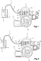
- the device 1 according to the invention, as illustrated in FIG. figure 1 , comprises a pump 2 powered by a battery, not shown.
- the pump 2 is connected inside an enclosure 3 of a servomotor 4 by means of a duct 5.
- the device 1 further comprises a non-return valve 6 and a pressure sensor 7, arranged successively along the duct 5, between the pump 2 and the enclosure 3.
- an opening is made in the chamber 3 of the servomotor 4, in order to connect the pump 2 to the Servomotor 4.
- the opening may be closed by a plug 8, which is for example screwed on the enclosure 3.
- the plug 8 is chosen so as to maintain the tightness of the enclosure 3 when the opening is closed by the cap 8.
- the plug 8 is unscrewed and an adapter screwed into the orifice of the servomotor 4 is connected to a quick connector 9 disposed at the end of the duct 5.
- the servomotor 4 typically comprises a motor assembly 11 adapted to generate a movement of a mechanical element, a set 12 of position detection of the mechanical element, and a set 13 comprising the mechanical element and a manual control system .
- the assembly 13 also comprises a communication space between the enclosure 3, a connector 16 and the motor assembly 11. The communication space is insulated and sealed vis-à-vis the mechanical element.
- the mechanical element of the assembly 13 is actuated by a manual control wheel 14 disposed outside the chamber 3.
- the position detection assembly 12 may be detachably connected, for example by screwing, to a connector 15.
- the connector 15 makes it possible to connect the position detection assembly 12 to a data transmission cable intended for the control system. external control.
- the assembly 13 can be removably connected, for example by screwing, to a connector 16.
- the connector 16 makes it possible to connect a power supply cable to a connection circuit of the assembly 13, said connection circuit being adapted to be connected to the motor assembly 11.
- the power supply cable can transmit to the servomotor 4 the command from the external control system.
- a first step the pressure inside the chamber 3 is reduced, using the pump 2, starting from an initial pressure, and up to a set pressure.
- the initial pressure in the servomotor is 1 bar (10 5 Pa). It has been found that a difference between the initial pressure inside the servomotor 4 and the set pressure of the order of 0.8 bar, between 0.7 and 0.9 bar, and preferably between 0, 75 and 0.85 bar, allowed an effective evaluation of the tightness.
- the pump 2 When the set pressure is reached, the pump 2 is stopped. Thanks to the non-return valve 6, which allows a passage of fluid only in one direction, from the chamber 3 to the pump 2, there is has no air passage in the chamber 3 via the conduit 5.
- the servomotor 4 If, after 15 minutes, the difference between the pressure inside the servomotor 4 and the set pressure is less than a predetermined value, or better, if the difference is zero, that is to say if no increase in pressure is visible, the servomotor 4 is considered sealed. Conversely, if the difference between the pressure inside the servomotor 4 and the set pressure is greater than a predetermined value, that is to say if we observe a rise in pressure inside the servomotor 4, the servomotor 4 is considered to be not waterproof.
- the method according to the invention involves a reduction of the pressure inside the chamber 3 of the booster 4, which has the advantage of making the seals of the booster 4 work in their direction of use,
- the process uses air, not water, which is more restrictive.
- the quick connector 9 is disconnected from the adapter 10, as shown in FIG. figure 2 , on which the elements identical to those of the figure 1 bear the same references.
- the adapter 10 constitutes a male part removably connected to the quick connector 9. The adapter 10 is then unscrewed, and then the plug 8 is screwed back.
- the method according to the invention is thus particularly simple to implement. It involves a lightweight device, transportable to the foot of the booster and allows local control of the seal. The method also makes it possible to control any type of sealing defect, for example a crack. A faulty or incorrectly positioned seal will be immediately detected.
- the purpose of the method is to assure the user that once everything is installed and electrically connected to the site, it will be possible to check the tightness of the servomotor. It will be able to do the same in case of intervention on the site before putting back into service the servomotor.
- the method makes it possible to check the tightness of the entire servomotor enclosure, including the connected parts, all the seals, the motor part, the sensor and connector area, in one test on the site and without external power supply.
- the method also makes it possible to guarantee the tightness of the servomotor when it is put into service or after any other operation. of maintenance.
- the leak test performed on a servomotor to be operated in the event of a nuclear accident ensures that the internal electrical equipment will operate under optimal conditions.
- test tool connects the test tool while the unit is mounted, electrically connected and verified on site.
- the test tool is independent, it can be equipped with a rechargeable battery allowing a test locally near the servomotor without mains power supply.
Landscapes
- Physics & Mathematics (AREA)
- General Physics & Mathematics (AREA)
- Examining Or Testing Airtightness (AREA)
- Monitoring And Testing Of Nuclear Reactors (AREA)
- Measuring Fluid Pressure (AREA)
- Permanent Magnet Type Synchronous Machine (AREA)
- Dc Machiner (AREA)
- Motor Or Generator Frames (AREA)
Description
- La présente invention a pour objet un procédé d'évaluation de l'étanchéité d'une enceinte d'un servomoteur. Elle a également pour objet un dispositif permettant de mettre en oeuvre le procédé.
- Un servomoteur est conçu pour générer un mouvement précis d'un élément mécanique, par exemple une vanne industrielle, selon une commande externe. Un servomoteur est ainsi un système motorisé capable d'atteindre des positions prédéterminées, puis de les maintenir. La position est, dans le cas d'un servomoteur rotatif, une position d'angle, et, dans le cas d'un servomoteur linéaire, une position de distance. Le démarrage et la conservation de la position prédéterminée sont commandés par la commande externe.
- Un paramètre important pour le bon fonctionnement du servomoteur est son étanchéité. En effet, dans certains environnements sous pression de fluide, comme par exemple dans les centrales nucléaires, les servomoteurs doivent pouvoir résister à des pressions de vapeur d'eau élevées, allant par exemple jusqu'à 5 ou 6 bars.
- Le servomoteur, bien que réputé étanche, peut présenter des défauts d'étanchéité dus par exemple à un joint défectueux ou à un câble électrique mal ajusté dans une entrée de câble du servomoteur. Si le servomoteur n'est pas parfaitement étanche, de la vapeur d'eau sous pression risque de pénétrer à l'intérieur du servomoteur et d'endommager l'équipement électrique du servomoteur.
- Il est connu de changer régulièrement les joints du servomoteur pour pallier ces problèmes d'étanchéité. Toutefois, les joints peuvent être mal montés. Il est également possible que le défaut d'étanchéité ne soit pas lié au joint, mais par exemple à une fissuration de l'enceinte du servomoteur. Le changement des joints ne permet donc pas de s'assurer dans tous les cas que le servomoteur est étanche.
- Il apparaît ainsi nécessaire de pouvoir évaluer de manière simple et fiable l'étanchéité d'une enceinte du servomoteur.
- L'invention propose un procédé permettant d'atteindre cet objectif. Des procédés et dispositifs d'évaluation de l'étanchéité d'une enceinte de l'art antérieur sont divulgués dans les documents
FR2849193 FR1315389 US3031884 etFR2761471 - L'invention a ainsi pour objet un procédé d'évaluation de l'étanchéité d'une enceinte d'un servomoteur, le servomoteur comprenant un ensemble moteur apte à générer un mouvement d'un élément mécanique, un ensemble de détection de position de l'élément mécanique relié de façon amovible à un connecteur, ainsi qu'un ensemble mécanique relié de façon amovible à un connecteur et comprenant l'élément mécanique et un système de commande manuelle, l'ensemble mécanique comprenant également un espace de communication entre l'enceinte, le connecteur et l'ensemble moteur, l'espace de communication étant isolé et étanche vis-à-vis de l'élément mécanique, le procédé étant mis en oeuvre en configuration opérationnelle du servomoteur, les connecteurs munis de leurs câbles respectifs étant installés, de manière à tester l'étanchéité de l'ensemble moteur, de l'ensemble de détection de position et des connecteurs.
- Le procédé selon l'invention comprend les étapes suivantes :
- une étape de diminution de la pression à l'intérieur de ladite enceinte, à partir d'une pression initiale, et jusqu'à une pression de consigne, par la mise en oeuvre d'un moyen d'aspiration de fluide raccordé au servomoteur à l'aide d'une ouverture de l'enceinte, l'ouverture étant apte à être fermée par un bouchon,
- lorsque la pression à l'intérieur de ladite enceinte est égale à la pression de consigne, une étape de détermination de l'évolution de la pression à l'intérieur de ladite enceinte en fonction du temps, pendant un intervalle de temps prédéterminé, le moyen d'aspiration de fluide n'étant plus mis en oeuvre pendant cette étape, ledit moyen d'aspiration de fluide étant en outre relié à ladite enceinte de manière à empêcher, entre le moyen d'aspiration de fluide et l'enceinte, tout passage de fluide en sens inverse du sens d'aspiration de fluide, et
- une étape d'évaluation de l'étanchéité de l'enceinte du servomoteur en fonction de l'évolution de pression déterminée.
- L'enceinte du servomoteur peut être considérée comme étanche si, pendant l'évolution de pression déterminée, la différence entre la pression à l'intérieur de l'enceinte du servomoteur et la pression de consigne est inférieure à une valeur prédéterminée.
- La pression initiale à l'intérieur de l'enceinte du servomoteur est avantageusement de 1 bar.
- La différence entre la pression initiale à l'intérieur de l'enceinte du servomoteur et la pression de consigne est de préférence comprise entre 0,7 et 0,9 bar, et encore plus préférentiellement entre 0,75 et 0,85 bar.
- La durée de l'intervalle de temps prédéterminé de l'étape de détermination de l'évolution de pression est de préférence comprise entre 10 et 20 minutes.
- Le procédé peut être mis en oeuvre dans une centrale nucléaire.
- L'invention a également pour objet un dispositif d'évaluation de l'étanchéité d'une enceinte d'un servomoteur.
- Le dispositif selon l'invention comprend :
- un servomoteur comprenant un ensemble moteur apte à générer un mouvement d'un élément mécanique, un ensemble de détection de position de l'élément mécanique relié de façon amovible à un connecteur, ainsi qu'un ensemble mécanique relié de façon amovible à un connecteur et comprenant l'élément mécanique et un système de commande manuelle, l'ensemble mécanique comprenant également un espace de communication entre l'enceinte, le connecteur et l'ensemble moteur, l'espace de communication étant isolé et étanche vis-à-vis de l'élément mécanique, les connecteurs munis de leurs câbles respectifs étant installés, de manière à tester l'étanchéité de l'ensemble moteur, de l'ensemble de détection de position et des connecteurs,
- un moyen d'aspiration de fluide raccordé au servomoteur à l'aide d'une ouverture de l'enceinte, l'ouverture étant apte à être fermée par un bouchon,
- un moyen permettant d'empêcher, entre le moyen d'aspiration de fluide et l'enceinte, tout passage de fluide en sens inverse du sens d'aspiration de fluide, et
- un moyen de mesure de la pression à l'intérieur de l'enceinte.
- Le moyen d'aspiration de fluide peut être une pompe, et le moyen permettant d'empêcher tout passage de fluide en sens inverse du sens d'aspiration de fluide peut être un dispositif anti-retour, comme par exemple un clapet anti-retour.
- Les avantages ainsi que d'autres particularités de l'invention seront détaillés dans la description qui suit, donnée uniquement à titre d'exemple non limitatif, et faite en référence aux dessins annexés sur lesquels :
- la
figure 1 illustre schématiquement un dispositif permettant de mettre en oeuvre le procédé selon l'invention, en configuration opérationnelle du dispositif, et - la
figure 2 illustre schématiquement le dispositif à l'issue du procédé. - Le dispositif 1 selon l'invention, tel qu'illustré à la
figure 1 , comprend une pompe 2 alimentée par une batterie, non représentée. La pompe 2 est reliée à l'intérieur d'une enceinte 3 d'un servomoteur 4 à l'aide d'un conduit 5. Le dispositif 1 comprend en outre un clapet anti-retour 6 et un capteur de pression 7, disposés successivement le long du conduit 5, entre la pompe 2 et l'enceinte 3. - Pour mettre en oeuvre le procédé, on réalise une ouverture dans l'enceinte 3 du servomoteur 4, afin de raccorder la pompe 2 au servomoteur 4. L'ouverture peut être fermée par un bouchon 8, qui est par exemple vissé sur l'enceinte 3. Le bouchon 8 est choisi de manière à pouvoir maintenir l'étanchéité de l'enceinte 3 lorsque l'ouverture est fermée par le bouchon 8.
- Pour raccorder la pompe 2 au servomoteur 4, on dévisse le bouchon 8 et un adaptateur vissé dans l'orifice du servomoteur 4 est connecté à un raccord rapide 9 disposé à l'extrémité du conduit 5.
- Le servomoteur 4 comprend typiquement un ensemble moteur 11 apte à générer un mouvement d'un élément mécanique, un ensemble 12 de détection de position de l'élément mécanique, ainsi qu'un ensemble 13 comprenant l'élément mécanique et un système de commande manuelle. L'ensemble 13 comprend également un espace de communication entre l'enceinte 3, un connecteur 16 et l'ensemble moteur 11. L'espace de communication est isolé et étanche vis-à-vis de l'élément mécanique. L'élément mécanique de l'ensemble 13 est actionné par un volant 14 de commande manuelle disposé en dehors de l'enceinte 3.
- L'ensemble 12 de détection de position peut être relié de façon amovible, par exemple par vissage, à un connecteur 15. Le connecteur 15 permet de connecter l'ensemble 12 de détection de position à un câble de transmission de données destiné au système de commande externe. De la même façon, l'ensemble 13 peut être relié de façon amovible, par exemple par vissage, à un connecteur 16. Le connecteur 16 permet de connecter un câble d'alimentation électrique à un circuit de connexion de l'ensemble 13, ledit circuit de connexion étant apte à être connecté à l'ensemble moteur 11. Le câble d'alimentation électrique permet de transmettre au servomoteur 4 la commande en provenance du système externe de commande.
- Avant de tester l'étanchéité, on s'assure que les connecteurs 15,16 munis de leurs câbles respectifs sont installés. On peut ainsi tester l'étanchéité de l'ensemble moteur 11, de l'ensemble 12 de détection de position, et des connecteurs 15,16.
- Une fois la pompe 2 raccordée à l'enceinte 3, le procédé d'évaluation de l'étanchéité peut être mis en oeuvre.
- Dans une première étape, on diminue la pression à l'intérieur de l'enceinte 3, à l'aide de la pompe 2, en partant d'une pression initiale, et jusqu'à une pression de consigne.
- La pression initiale régnant dans le servomoteur est de 1 bar (105 Pa). On a constaté qu'une différence entre la pression initiale à l'intérieur du servomoteur 4 et la pression de consigne de l'ordre de 0,8 bar, comprise entre 0,7 et 0,9 bar, et de préférence entre 0,75 et 0,85 bar, permettait une évaluation efficace de l'étanchéité.
- Lorsque la pression de consigne est atteinte, on stoppe la pompe 2. Grâce au clapet anti-retour 6, qui n'autorise un passage de fluide que dans un seul sens, depuis l'enceinte 3 vers la pompe 2, il n'y a pas de passage d'air dans l'enceinte 3 via le conduit 5.
- Dans une deuxième étape, on observe l'évolution de la pression au cours du temps, à l'aide du capteur de pression 7. Avec une dépression de l'ordre de 0,8 bar, on a constaté que l'étanchéité pouvait être évaluée de façon efficace en observant la pression à l'issue d'un intervalle de temps commençant au stoppage de la pompe 2 et de durée comprise entre 10 et 20 minutes, et notamment d'environ 15 minutes.
- Si, après 15 minutes, la différence entre la pression à l'intérieur du servomoteur 4 et la pression de consigne est inférieure à une valeur prédéterminée, ou mieux, si la différence est nulle, c'est-à-dire si aucune remontée de pression n'est visible, le servomoteur 4 est considéré comme étanche. A l'inverse, si la différence entre la pression à l'intérieur du servomoteur 4 et la pression de consigne est supérieure à une valeur prédéterminée, c'est-à-dire si on observe une remontée de pression à l'intérieure du servomoteur 4, le servomoteur 4 est considéré comme n'étant pas étanche.
- Le procédé selon l'invention fait intervenir une diminution de la pression à l'intérieur de l'enceinte 3 du servomoteur 4, ce qui a pour avantage de faire travailler les joints d'étanchéité du servomoteur 4 dans leur sens d'utilisation, de l'extérieur vers l'intérieur du servomoteur 4. En outre, le procédé met en oeuvre de l'air, et non de l'eau, ce qui est plus contraignant.
- Lorsque le procédé est terminé, le raccord rapide 9 est déconnecté de l'adaptateur 10, tel qu'illustré à la
figure 2 , sur laquelle les éléments identiques à ceux de lafigure 1 portent les mêmes références. L'adaptateur 10 constitue une partie mâle reliée de manière amovible au raccord rapide 9. On dévisse ensuite l'adaptateur 10, puis le bouchon 8 est revissé. - Le procédé selon l'invention est ainsi particulièrement simple à mettre en oeuvre. Il fait intervenir un dispositif léger, transportable au pied du servomoteur et qui permet un contrôle local de l'étanchéité. Le procédé permet en outre de contrôler tout type de défaut d'étanchéité, par exemple une fissure. Un joint défectueux ou mal positionné sera immédiatement détecté.
- Le procédé a pour but d'assurer à l'utilisateur qu'une fois tout installé et raccordé électriquement sur le site, il lui sera possible de vérifier l'étanchéité du servomoteur. Il pourra faire de même en cas d'intervention sur le site avant de remettre en service le servomoteur.
- Le procédé permet de vérifier l'étanchéité de toute l'enceinte du servomoteur, y compris les pièces raccordées, tous les joints d'étanchéité, la partie moteur, la zone des capteurs et des connecteurs, en un seul test sur le site et sans alimentation externe.
- Le procédé permet également de garantir l'étanchéité du servomoteur lors de sa mise en service ou après toute autre opération de maintenance. Le test d'étanchéité effectué sur un servomoteur devant fonctionner en cas d'accident nucléaire permet de garantir que l'équipement électrique interne fonctionnera dans des conditions optimales.
- Un raccord, facile d'accès, permet de connecter l'outil de test alors que l'appareil est monté, raccordé électriquement et vérifié sur le site. L'outil de test est indépendant, il peut être équipé d'une batterie rechargeable permettant un test localement près du servomoteur sans alimentation électrique du secteur.
- Enfin, les interventions sur le site nécessitant l'ouverture des capots du servomoteur par différentes équipes, le procédé permet de valider l'étanchéité après la fermeture des capots.
Claims (9)
- Procédé d'évaluation de l'étanchéité d'une enceinte (3) d'un servomoteur (4), le servomoteur (4) comprenant un ensemble moteur (11) apte à générer un mouvement d'un élément mécanique, un ensemble (12) de détection de position de l'élément mécanique relié de façon amovible à un connecteur (15), ainsi qu'un ensemble mécanique (13) relié de façon amovible à un connecteur (16) et comprenant l'élément mécanique et un système de commande manuelle, l'ensemble mécanique (13) comprenant également un espace de communication entre l'enceinte (3), le connecteur (16) et l'ensemble moteur (11), l'espace de communication étant isolé et étanche vis-à-vis de l'élément mécanique, le procédé étant mis en oeuvre en configuration opérationnelle du servomoteur (4), les connecteurs (15, 16) munis de leurs câbles respectifs étant installés, de manière à tester l'étanchéité de l'ensemble moteur (11), de l'ensemble (12) de détection de position et des connecteurs (15,16), caractérisé en ce que le procédé comprend les étapes suivantes :- une étape de diminution de la pression à l'intérieur de ladite enceinte (3), à partir d'une pression initiale, et jusqu'à une pression de consigne, par la mise en oeuvre d'un moyen (2) d'aspiration de fluide raccordé au servomoteur (4) à l'aide d'une ouverture de l'enceinte (3), l'ouverture étant apte à être fermée par un bouchon (8),- lorsque la pression à l'intérieur de ladite enceinte (3) est égale à la pression de consigne, une étape de détermination de l'évolution de la pression à l'intérieur de ladite enceinte (3) en fonction du temps, pendant un intervalle de temps prédéterminé, le moyen (2) d'aspiration de fluide n'étant plus mis en oeuvre pendant cette étape, ledit moyen (2) d'aspiration de fluide étant en outre relié à ladite enceinte (3) de manière à empêcher, entre le moyen (2) d'aspiration de fluide et l'enceinte (3), tout passage de fluide en sens inverse du sens d'aspiration de fluide, et- une étape d'évaluation de l'étanchéité de l'enceinte (3) du servomoteur (4) en fonction de l'évolution de pression déterminée.
- Procédé selon la revendication 1, caractérisé en ce que l'enceinte (3) du servomoteur (4) est considérée comme étanche si, pendant l'évolution de pression déterminée, la différence entre la pression à l'intérieur de l'enceinte (3) du servomoteur (4) et la pression de consigne est inférieure à une valeur prédéterminée.
- Procédé selon l'une des revendications 1 ou 2, caractérisé en ce que la pression initiale à l'intérieur de l'enceinte (3) du servomoteur (4) est de 1 bar.
- Procédé selon la revendication 3, caractérisé en ce que la différence entre la pression initiale à l'intérieur de l'enceinte (3) du servomoteur (4) et la pression de consigne est comprise entre 0,7 et 0,9 bar.
- Procédé selon la revendication 3 ou 4, caractérisé en ce que la différence entre la pression initiale à l'intérieur de l'enceinte (3) du servomoteur (4) et la pression de consigne est comprise entre 0,75 et 0,85 bar.
- Procédé selon la revendication 4 ou 5, caractérisé en ce que la durée de l'intervalle de temps prédéterminé de l'étape de détermination de l'évolution de pression est comprise entre 10 et 20 minutes.
- Procédé selon l'une des revendications 1 à 6, caractérisé en ce qu'il est mis en oeuvre dans une centrale nucléaire.
- Ensemble comprenant un dispositif (1) d'évaluation de l'étanchéité d'une enceinte (3) et un servomoteur (4), caractérisé en ce qu'il comprend :- un servomoteur (4) comprenant un ensemble moteur (11) apte à générer un mouvement d'un élément mécanique, un ensemble (12) de détection de position de l'élément mécanique relié de façon amovible à un connecteur (15), ainsi qu'un ensemble mécanique (13) relié de façon amovible à un connecteur (16) et comprenant l'élément mécanique et un système de commande manuelle, l'ensemble mécanique (13) comprenant également un espace de communication entre l'enceinte (3) du servomoteur, le connecteur (16) et l'ensemble moteur (11), l'espace de communication étant isolé et étanche vis-à-vis de l'élément mécanique, les connecteurs (15,16) munis de leurs câbles respectifs étant installés, de manière à tester l'étanchéité de l'ensemble moteur (11), de l'ensemble (12) de détection de position et des connecteurs (15, 16), en configuration opérationnelle du servomoteur,- un moyen (2) d'aspiration de fluide destiné à être raccordé, lors d'une évaluation de l'étanchéité de l'enceinte (3) du servomoteur, au servomoteur (4) à l'aide d'une ouverture de l'enceinte (3), l'ouverture étant apte à être fermée par un bouchon (8),- un moyen (6) permettant d'empêcher, entre le moyen (2) d'aspiration de fluide et l'enceinte (3) lors d'une utilisation, tout passage de fluide en sens inverse du sens d'aspiration de fluide, et- un moyen (7) de mesure de la pression à l'intérieur de l'enceinte (3) lors de l'évaluation.
- Ensemble selon la revendication 8, caractérisé en ce que le moyen (2) d'aspiration de fluide est une pompe (2), et en ce que le moyen (6) permettant d'empêcher tout passage de fluide en sens inverse du sens d'aspiration de fluide est un dispositif antiretour (6).
Priority Applications (3)
| Application Number | Priority Date | Filing Date | Title |
|---|---|---|---|
| SI200931954T SI2350601T1 (sl) | 2008-11-28 | 2009-11-23 | Metoda za ocenjevanje tesnila ohišja za servomotor |
| HRP20190547TT HRP20190547T1 (hr) | 2008-11-28 | 2009-11-23 | Postupak provjeravanja nepropusnosti kućišta servomotora |
| PL09795492T PL2350601T3 (pl) | 2008-11-28 | 2009-11-23 | Sposób oceniania szczelności obudowy serwomotoru |
Applications Claiming Priority (2)
| Application Number | Priority Date | Filing Date | Title |
|---|---|---|---|
| FR0858105A FR2939196B1 (fr) | 2008-11-28 | 2008-11-28 | Procede d'evaluation de l'etancheite d'une enceinte d'un servomoteur |
| PCT/FR2009/052256 WO2010061109A2 (fr) | 2008-11-28 | 2009-11-23 | Procédé d'évaluation de l'étanchéité d'une enceinte d'un servomoteur |
Publications (2)
| Publication Number | Publication Date |
|---|---|
| EP2350601A2 EP2350601A2 (fr) | 2011-08-03 |
| EP2350601B1 true EP2350601B1 (fr) | 2019-01-09 |
Family
ID=40874760
Family Applications (1)
| Application Number | Title | Priority Date | Filing Date |
|---|---|---|---|
| EP09795492.9A Active EP2350601B1 (fr) | 2008-11-28 | 2009-11-23 | Procédé d'évaluation de l'étanchéité d'une enceinte d'un servomoteur |
Country Status (13)
| Country | Link |
|---|---|
| US (1) | US8402818B2 (fr) |
| EP (1) | EP2350601B1 (fr) |
| CN (1) | CN102227621B (fr) |
| ES (1) | ES2718815T3 (fr) |
| FR (1) | FR2939196B1 (fr) |
| HR (1) | HRP20190547T1 (fr) |
| HU (1) | HUE043525T2 (fr) |
| LT (1) | LT2350601T (fr) |
| PL (1) | PL2350601T3 (fr) |
| RU (1) | RU2536761C2 (fr) |
| SI (1) | SI2350601T1 (fr) |
| TR (1) | TR201904682T4 (fr) |
| WO (1) | WO2010061109A2 (fr) |
Families Citing this family (4)
| Publication number | Priority date | Publication date | Assignee | Title |
|---|---|---|---|---|
| FR2990236B1 (fr) * | 2012-05-07 | 2014-04-25 | Eurocopter France | Dispositif de controle par depressurisation de l'etancheite d'une boite de transmission d'un giravion |
| TWI576858B (zh) * | 2015-10-16 | 2017-04-01 | 行政院原子能委員會核能研究所 | 核能級控制閥檢驗測試系統 |
| DE102015015636A1 (de) * | 2015-12-02 | 2017-06-08 | Fresenius Medical Deutschland Gmbh | Verfahren zum Testen der Rigidität eines Disposables |
| CN108331576B (zh) * | 2018-02-05 | 2020-08-11 | 王艳霞 | 一种单向流量监测装置 |
Family Cites Families (13)
| Publication number | Priority date | Publication date | Assignee | Title |
|---|---|---|---|---|
| US3031884A (en) * | 1956-07-02 | 1962-05-01 | Bendix Corp | Leak test equipment |
| FR1315389A (fr) * | 1956-07-02 | 1963-01-18 | Bendix Corp | Détecteur de fuites |
| SU842439A1 (ru) * | 1974-04-04 | 1981-06-30 | Britvin Lev N | Способ проверки герметичностиКлАпАННОгО узлА пОРшНЕВОгО HACOCA |
| US4178208A (en) * | 1978-02-23 | 1979-12-11 | The United States Of America As Represented By The United States Department Of Energy | Self locking drive system for rotating plug of a nuclear reactor |
| AT379672B (de) * | 1983-01-21 | 1986-02-10 | Schrack Elektronik Ag | Regelventil fuer heizkoerper |
| SU1631339A1 (ru) * | 1988-08-17 | 1991-02-28 | Ленинградский институт инженеров железнодорожного транспорта им.акад.В.Н.Образцова | Способ проверки внутренних полостей двигателей внутреннего сгорани на герметичность |
| DE3900866C2 (de) * | 1989-01-13 | 2001-11-22 | Heimeier Gmbh Metall Theodor | Anordnung zur Steuerung eines Heiz- oder Kühlmediums |
| JPH0774370A (ja) * | 1993-09-06 | 1995-03-17 | Mitsuteru Kimura | ピエゾデバイス |
| FR2761471B1 (fr) * | 1997-03-28 | 1999-06-18 | Abp Arizzoli Bernard Et Perre | Procede et ensemble de detection de fuites d'une installation a tube caloporteur place dans une gaine |
| FR2849193B1 (fr) * | 2002-12-19 | 2005-04-22 | Euraltech Sa | Procede pour tester l'etancheite d'une piece creuse |
| RU2224988C1 (ru) * | 2003-04-15 | 2004-02-27 | Всероссийский научно-исследовательский технологический институт ремонта и эксплуатации машинно-тракторного парка | Устройство для определения технического состояния цилиндропоршневой группы двигателя внутреннего сгорания |
| CN2783384Y (zh) * | 2005-04-27 | 2006-05-24 | 袁卫华 | 一体化智能伺服电机 |
| FR2898393B1 (fr) * | 2006-03-08 | 2009-02-20 | Bernard Sa L | Antidevireur a ressort. |
-
2008
- 2008-11-28 FR FR0858105A patent/FR2939196B1/fr active Active
-
2009
- 2009-11-23 HR HRP20190547TT patent/HRP20190547T1/hr unknown
- 2009-11-23 HU HUE09795492A patent/HUE043525T2/hu unknown
- 2009-11-23 WO PCT/FR2009/052256 patent/WO2010061109A2/fr not_active Ceased
- 2009-11-23 US US13/055,172 patent/US8402818B2/en active Active
- 2009-11-23 ES ES09795492T patent/ES2718815T3/es active Active
- 2009-11-23 LT LTEP09795492.9T patent/LT2350601T/lt unknown
- 2009-11-23 PL PL09795492T patent/PL2350601T3/pl unknown
- 2009-11-23 CN CN200980147703.4A patent/CN102227621B/zh active Active
- 2009-11-23 TR TR2019/04682T patent/TR201904682T4/tr unknown
- 2009-11-23 RU RU2011104008/28A patent/RU2536761C2/ru active IP Right Revival
- 2009-11-23 SI SI200931954T patent/SI2350601T1/sl unknown
- 2009-11-23 EP EP09795492.9A patent/EP2350601B1/fr active Active
Non-Patent Citations (1)
| Title |
|---|
| None * |
Also Published As
| Publication number | Publication date |
|---|---|
| RU2536761C2 (ru) | 2014-12-27 |
| EP2350601A2 (fr) | 2011-08-03 |
| ES2718815T3 (es) | 2019-07-04 |
| WO2010061109A2 (fr) | 2010-06-03 |
| US20110120234A1 (en) | 2011-05-26 |
| PL2350601T3 (pl) | 2019-08-30 |
| CN102227621B (zh) | 2015-08-12 |
| TR201904682T4 (tr) | 2019-05-21 |
| WO2010061109A3 (fr) | 2010-07-22 |
| HUE043525T2 (hu) | 2019-08-28 |
| RU2011104008A (ru) | 2012-08-20 |
| FR2939196A1 (fr) | 2010-06-04 |
| SI2350601T1 (sl) | 2019-07-31 |
| CN102227621A (zh) | 2011-10-26 |
| LT2350601T (lt) | 2019-06-25 |
| FR2939196B1 (fr) | 2010-12-10 |
| US8402818B2 (en) | 2013-03-26 |
| HRP20190547T1 (hr) | 2019-07-12 |
Similar Documents
| Publication | Publication Date | Title |
|---|---|---|
| EP0038492A1 (fr) | Dispositif de contrôle de fuite pour poste blindé à haute tension | |
| WO2010061109A2 (fr) | Procédé d'évaluation de l'étanchéité d'une enceinte d'un servomoteur | |
| WO2011051631A2 (fr) | Systeme de transmission de puissance electrique a travers une paroi | |
| EP4249750B1 (fr) | Pompe peristaltique etanche pour appareil electromenager | |
| EP3237788B1 (fr) | Adaptateur de test ou de remplissage | |
| EP3394472B1 (fr) | Conduit electrique et de passage de fluide pour controler une etancheite dans un frein de vehicule | |
| FR2959613A1 (fr) | Systeme de raccordement permettant de signaler le couple de serrage d'une borne a vis. | |
| EP3568683B1 (fr) | Dispositif et procede de test d'etancheite | |
| FR2940431A1 (fr) | Dispositif de mesure d'une grandeur telle la pression a l'interieur d'une cuve remplie d'un gaz ou d'un liquide | |
| EP3039757B1 (fr) | Dispositif de confinement des fuites de gaz se produisant au niveau d'un disque de rupture d'un compartiment d'un poste electrique ou d'un disjoncteur a haute tension a isolation gazeuse | |
| EP3853574B1 (fr) | Système de test de l'étanchéité d'un presse-étoupe de traversée d'une cloison notamment d'un connecteur électrique immergeable | |
| JP4155959B2 (ja) | ガス圧検圧用接続具 | |
| WO2014154967A1 (fr) | Procede de localisation de defaut electrique dans un systeme modulaire de distribution electrique sous-marin | |
| JP2005083910A (ja) | 漏洩点検治具 | |
| EP3685087A1 (fr) | Systeme de connexion entre un organe de distribution et un organe de reception et procede de detection de fuite | |
| FR3107034A1 (fr) | Dispositif d’obturation d’une entrée d’air d’aéronef destiné à participer au contrôle de l’étanchéité d’au moins un réservoir de l’aéronef. | |
| WO2023095056A1 (fr) | Procédé de colmatage d'une jonction à surface et contre-surface de contact d'un élément d'un compartiment de poste électrique sous enveloppe métallique à isolation gazeuse et jonction résultante | |
| EP2431724A1 (fr) | Organe de châssis d'un véhicule automobile équipé d'un moyen d'étanchéité entourant une ouverture | |
| FR2910888A1 (fr) | Dispositif de recuperation de fluide. | |
| FR3050176B1 (fr) | Nacelle pour ensemble propulsif | |
| FR3118168A1 (fr) | Dispositif de test d’étanchéité d’une manche de télémanipulateur et procédé de test d’étanchéité mettant en œuvre un tel dispositif en cellule blindée | |
| FR3016808A1 (fr) | Module de captage d'un gaz dissous dans un liquide et dispositif de mesure | |
| FR3039245A1 (fr) | Traceur de canalisations | |
| FR2498020A1 (fr) | Dispositif d'etancheite pour passage de conducteurs electriques | |
| FR2996903A1 (fr) | Dispositif de connexion a une canalisation sous pression sans rupture de confinement |
Legal Events
| Date | Code | Title | Description |
|---|---|---|---|
| PUAI | Public reference made under article 153(3) epc to a published international application that has entered the european phase |
Free format text: ORIGINAL CODE: 0009012 |
|
| 17P | Request for examination filed |
Effective date: 20110221 |
|
| AK | Designated contracting states |
Kind code of ref document: A2 Designated state(s): AT BE BG CH CY CZ DE DK EE ES FI FR GB GR HR HU IE IS IT LI LT LU LV MC MK MT NL NO PL PT RO SE SI SK SM TR |
|
| DAX | Request for extension of the european patent (deleted) | ||
| STAA | Information on the status of an ep patent application or granted ep patent |
Free format text: STATUS: EXAMINATION IS IN PROGRESS |
|
| 17Q | First examination report despatched |
Effective date: 20170329 |
|
| GRAP | Despatch of communication of intention to grant a patent |
Free format text: ORIGINAL CODE: EPIDOSNIGR1 |
|
| STAA | Information on the status of an ep patent application or granted ep patent |
Free format text: STATUS: GRANT OF PATENT IS INTENDED |
|
| INTG | Intention to grant announced |
Effective date: 20180726 |
|
| GRAS | Grant fee paid |
Free format text: ORIGINAL CODE: EPIDOSNIGR3 |
|
| GRAA | (expected) grant |
Free format text: ORIGINAL CODE: 0009210 |
|
| STAA | Information on the status of an ep patent application or granted ep patent |
Free format text: STATUS: THE PATENT HAS BEEN GRANTED |
|
| AK | Designated contracting states |
Kind code of ref document: B1 Designated state(s): AT BE BG CH CY CZ DE DK EE ES FI FR GB GR HR HU IE IS IT LI LT LU LV MC MK MT NL NO PL PT RO SE SI SK SM TR |
|
| REG | Reference to a national code |
Ref country code: GB Ref legal event code: FG4D Free format text: NOT ENGLISH |
|
| REG | Reference to a national code |
Ref country code: CH Ref legal event code: EP Ref country code: AT Ref legal event code: REF Ref document number: 1087915 Country of ref document: AT Kind code of ref document: T Effective date: 20190115 |
|
| REG | Reference to a national code |
Ref country code: DE Ref legal event code: R096 Ref document number: 602009056659 Country of ref document: DE |
|
| REG | Reference to a national code |
Ref country code: IE Ref legal event code: FG4D Free format text: LANGUAGE OF EP DOCUMENT: FRENCH |
|
| REG | Reference to a national code |
Ref country code: HR Ref legal event code: TUEP Ref document number: P20190547 Country of ref document: HR |
|
| REG | Reference to a national code |
Ref country code: RO Ref legal event code: EPE |
|
| REG | Reference to a national code |
Ref country code: NL Ref legal event code: MP Effective date: 20190109 |
|
| REG | Reference to a national code |
Ref country code: EE Ref legal event code: FG4A Ref document number: E017326 Country of ref document: EE Effective date: 20190404 |
|
| PG25 | Lapsed in a contracting state [announced via postgrant information from national office to epo] |
Ref country code: NL Free format text: LAPSE BECAUSE OF FAILURE TO SUBMIT A TRANSLATION OF THE DESCRIPTION OR TO PAY THE FEE WITHIN THE PRESCRIBED TIME-LIMIT Effective date: 20190109 |
|
| REG | Reference to a national code |
Ref country code: ES Ref legal event code: FG2A Ref document number: 2718815 Country of ref document: ES Kind code of ref document: T3 Effective date: 20190704 |
|
| REG | Reference to a national code |
Ref country code: HR Ref legal event code: T1PR Ref document number: P20190547 Country of ref document: HR |
|
| PG25 | Lapsed in a contracting state [announced via postgrant information from national office to epo] |
Ref country code: PT Free format text: LAPSE BECAUSE OF FAILURE TO SUBMIT A TRANSLATION OF THE DESCRIPTION OR TO PAY THE FEE WITHIN THE PRESCRIBED TIME-LIMIT Effective date: 20190509 Ref country code: NO Free format text: LAPSE BECAUSE OF FAILURE TO SUBMIT A TRANSLATION OF THE DESCRIPTION OR TO PAY THE FEE WITHIN THE PRESCRIBED TIME-LIMIT Effective date: 20190409 Ref country code: SE Free format text: LAPSE BECAUSE OF FAILURE TO SUBMIT A TRANSLATION OF THE DESCRIPTION OR TO PAY THE FEE WITHIN THE PRESCRIBED TIME-LIMIT Effective date: 20190109 |
|
| REG | Reference to a national code |
Ref country code: SK Ref legal event code: T3 Ref document number: E 30722 Country of ref document: SK |
|
| REG | Reference to a national code |
Ref country code: HU Ref legal event code: AG4A Ref document number: E043525 Country of ref document: HU |
|
| PG25 | Lapsed in a contracting state [announced via postgrant information from national office to epo] |
Ref country code: GR Free format text: LAPSE BECAUSE OF FAILURE TO SUBMIT A TRANSLATION OF THE DESCRIPTION OR TO PAY THE FEE WITHIN THE PRESCRIBED TIME-LIMIT Effective date: 20190410 Ref country code: IS Free format text: LAPSE BECAUSE OF FAILURE TO SUBMIT A TRANSLATION OF THE DESCRIPTION OR TO PAY THE FEE WITHIN THE PRESCRIBED TIME-LIMIT Effective date: 20190509 |
|
| REG | Reference to a national code |
Ref country code: DE Ref legal event code: R097 Ref document number: 602009056659 Country of ref document: DE |
|
| PG25 | Lapsed in a contracting state [announced via postgrant information from national office to epo] |
Ref country code: DK Free format text: LAPSE BECAUSE OF FAILURE TO SUBMIT A TRANSLATION OF THE DESCRIPTION OR TO PAY THE FEE WITHIN THE PRESCRIBED TIME-LIMIT Effective date: 20190109 |
|
| PLBE | No opposition filed within time limit |
Free format text: ORIGINAL CODE: 0009261 |
|
| STAA | Information on the status of an ep patent application or granted ep patent |
Free format text: STATUS: NO OPPOSITION FILED WITHIN TIME LIMIT |
|
| PG25 | Lapsed in a contracting state [announced via postgrant information from national office to epo] |
Ref country code: SM Free format text: LAPSE BECAUSE OF FAILURE TO SUBMIT A TRANSLATION OF THE DESCRIPTION OR TO PAY THE FEE WITHIN THE PRESCRIBED TIME-LIMIT Effective date: 20190109 |
|
| REG | Reference to a national code |
Ref country code: HR Ref legal event code: ODRP Ref document number: P20190547 Country of ref document: HR Payment date: 20191115 Year of fee payment: 11 |
|
| 26N | No opposition filed |
Effective date: 20191010 |
|
| REG | Reference to a national code |
Ref country code: CH Ref legal event code: PL |
|
| PG25 | Lapsed in a contracting state [announced via postgrant information from national office to epo] |
Ref country code: MC Free format text: LAPSE BECAUSE OF FAILURE TO SUBMIT A TRANSLATION OF THE DESCRIPTION OR TO PAY THE FEE WITHIN THE PRESCRIBED TIME-LIMIT Effective date: 20190109 Ref country code: LI Free format text: LAPSE BECAUSE OF NON-PAYMENT OF DUE FEES Effective date: 20191130 Ref country code: CH Free format text: LAPSE BECAUSE OF NON-PAYMENT OF DUE FEES Effective date: 20191130 Ref country code: LU Free format text: LAPSE BECAUSE OF NON-PAYMENT OF DUE FEES Effective date: 20191123 |
|
| PG25 | Lapsed in a contracting state [announced via postgrant information from national office to epo] |
Ref country code: IE Free format text: LAPSE BECAUSE OF NON-PAYMENT OF DUE FEES Effective date: 20191123 |
|
| REG | Reference to a national code |
Ref country code: HR Ref legal event code: ODRP Ref document number: P20190547 Country of ref document: HR Payment date: 20201104 Year of fee payment: 12 |
|
| PGFP | Annual fee paid to national office [announced via postgrant information from national office to epo] |
Ref country code: TR Payment date: 20201113 Year of fee payment: 12 |
|
| PGFP | Annual fee paid to national office [announced via postgrant information from national office to epo] |
Ref country code: LT Payment date: 20201109 Year of fee payment: 12 Ref country code: RO Payment date: 20201109 Year of fee payment: 12 Ref country code: EE Payment date: 20201124 Year of fee payment: 12 Ref country code: HU Payment date: 20201103 Year of fee payment: 12 Ref country code: ES Payment date: 20201217 Year of fee payment: 12 Ref country code: IT Payment date: 20201120 Year of fee payment: 12 Ref country code: CZ Payment date: 20201120 Year of fee payment: 12 Ref country code: HR Payment date: 20201104 Year of fee payment: 12 Ref country code: BG Payment date: 20201119 Year of fee payment: 12 Ref country code: AT Payment date: 20201118 Year of fee payment: 12 |
|
| PGFP | Annual fee paid to national office [announced via postgrant information from national office to epo] |
Ref country code: PL Payment date: 20201106 Year of fee payment: 12 Ref country code: LV Payment date: 20201124 Year of fee payment: 12 |
|
| REG | Reference to a national code |
Ref country code: EE Ref legal event code: HC1A Ref document number: E017326 Country of ref document: EE |
|
| PG25 | Lapsed in a contracting state [announced via postgrant information from national office to epo] |
Ref country code: CY Free format text: LAPSE BECAUSE OF FAILURE TO SUBMIT A TRANSLATION OF THE DESCRIPTION OR TO PAY THE FEE WITHIN THE PRESCRIBED TIME-LIMIT Effective date: 20190109 |
|
| REG | Reference to a national code |
Ref country code: AT Ref legal event code: UEP Ref document number: 1087915 Country of ref document: AT Kind code of ref document: T Effective date: 20190109 |
|
| PG25 | Lapsed in a contracting state [announced via postgrant information from national office to epo] |
Ref country code: MT Free format text: LAPSE BECAUSE OF FAILURE TO SUBMIT A TRANSLATION OF THE DESCRIPTION OR TO PAY THE FEE WITHIN THE PRESCRIBED TIME-LIMIT Effective date: 20190109 |
|
| PGFP | Annual fee paid to national office [announced via postgrant information from national office to epo] |
Ref country code: MK Payment date: 20201106 Year of fee payment: 12 |
|
| REG | Reference to a national code |
Ref country code: EE Ref legal event code: MM4A Ref document number: E017326 Country of ref document: EE Effective date: 20211130 |
|
| REG | Reference to a national code |
Ref country code: LT Ref legal event code: MM4D Effective date: 20211123 |
|
| REG | Reference to a national code |
Ref country code: HR Ref legal event code: PBON Ref document number: P20190547 Country of ref document: HR Effective date: 20211123 |
|
| REG | Reference to a national code |
Ref country code: AT Ref legal event code: MM01 Ref document number: 1087915 Country of ref document: AT Kind code of ref document: T Effective date: 20211123 |
|
| PG25 | Lapsed in a contracting state [announced via postgrant information from national office to epo] |
Ref country code: RO Free format text: LAPSE BECAUSE OF NON-PAYMENT OF DUE FEES Effective date: 20211123 Ref country code: LT Free format text: LAPSE BECAUSE OF NON-PAYMENT OF DUE FEES Effective date: 20211123 Ref country code: HU Free format text: LAPSE BECAUSE OF NON-PAYMENT OF DUE FEES Effective date: 20211124 Ref country code: EE Free format text: LAPSE BECAUSE OF NON-PAYMENT OF DUE FEES Effective date: 20211130 Ref country code: CZ Free format text: LAPSE BECAUSE OF NON-PAYMENT OF DUE FEES Effective date: 20211123 Ref country code: BG Free format text: LAPSE BECAUSE OF NON-PAYMENT OF DUE FEES Effective date: 20220531 |
|
| PG25 | Lapsed in a contracting state [announced via postgrant information from national office to epo] |
Ref country code: LV Free format text: LAPSE BECAUSE OF NON-PAYMENT OF DUE FEES Effective date: 20211123 Ref country code: AT Free format text: LAPSE BECAUSE OF NON-PAYMENT OF DUE FEES Effective date: 20211123 |
|
| PG25 | Lapsed in a contracting state [announced via postgrant information from national office to epo] |
Ref country code: HR Free format text: LAPSE BECAUSE OF NON-PAYMENT OF DUE FEES Effective date: 20211123 |
|
| PG25 | Lapsed in a contracting state [announced via postgrant information from national office to epo] |
Ref country code: IT Free format text: LAPSE BECAUSE OF NON-PAYMENT OF DUE FEES Effective date: 20211123 |
|
| REG | Reference to a national code |
Ref country code: ES Ref legal event code: FD2A Effective date: 20230228 |
|
| PG25 | Lapsed in a contracting state [announced via postgrant information from national office to epo] |
Ref country code: ES Free format text: LAPSE BECAUSE OF NON-PAYMENT OF DUE FEES Effective date: 20211124 |
|
| PG25 | Lapsed in a contracting state [announced via postgrant information from national office to epo] |
Ref country code: PL Free format text: LAPSE BECAUSE OF NON-PAYMENT OF DUE FEES Effective date: 20211123 |
|
| PG25 | Lapsed in a contracting state [announced via postgrant information from national office to epo] |
Ref country code: TR Free format text: LAPSE BECAUSE OF NON-PAYMENT OF DUE FEES Effective date: 20211123 |
|
| PGFP | Annual fee paid to national office [announced via postgrant information from national office to epo] |
Ref country code: DE Payment date: 20251201 Year of fee payment: 17 |
|
| PGFP | Annual fee paid to national office [announced via postgrant information from national office to epo] |
Ref country code: GB Payment date: 20251125 Year of fee payment: 17 |
|
| PGFP | Annual fee paid to national office [announced via postgrant information from national office to epo] |
Ref country code: FI Payment date: 20251128 Year of fee payment: 17 |
|
| PGFP | Annual fee paid to national office [announced via postgrant information from national office to epo] |
Ref country code: FR Payment date: 20251006 Year of fee payment: 17 |
|
| PGFP | Annual fee paid to national office [announced via postgrant information from national office to epo] |
Ref country code: BE Payment date: 20251125 Year of fee payment: 17 |
|
| PGFP | Annual fee paid to national office [announced via postgrant information from national office to epo] |
Ref country code: SK Payment date: 20251024 Year of fee payment: 17 |
|
| PGFP | Annual fee paid to national office [announced via postgrant information from national office to epo] |
Ref country code: SI Payment date: 20251027 Year of fee payment: 17 |