EP2350476B1 - Ensemble crochet et bijou utilisant ledit ensemble - Google Patents
Ensemble crochet et bijou utilisant ledit ensemble Download PDFInfo
- Publication number
- EP2350476B1 EP2350476B1 EP09817031.9A EP09817031A EP2350476B1 EP 2350476 B1 EP2350476 B1 EP 2350476B1 EP 09817031 A EP09817031 A EP 09817031A EP 2350476 B1 EP2350476 B1 EP 2350476B1
- Authority
- EP
- European Patent Office
- Prior art keywords
- hook
- orientation
- set forth
- assembly
- hook assembly
- Prior art date
- Legal status (The legal status is an assumption and is not a legal conclusion. Google has not performed a legal analysis and makes no representation as to the accuracy of the status listed.)
- Active
Links
- 230000006835 compression Effects 0.000 claims description 9
- 238000007906 compression Methods 0.000 claims description 9
- 239000007787 solid Substances 0.000 claims description 3
- 230000007246 mechanism Effects 0.000 description 19
- 239000000463 material Substances 0.000 description 15
- 239000000725 suspension Substances 0.000 description 9
- 239000002184 metal Substances 0.000 description 6
- 229910052751 metal Inorganic materials 0.000 description 6
- PXHVJJICTQNCMI-UHFFFAOYSA-N Nickel Chemical compound [Ni] PXHVJJICTQNCMI-UHFFFAOYSA-N 0.000 description 4
- 229930040373 Paraformaldehyde Natural products 0.000 description 4
- 229910000831 Steel Inorganic materials 0.000 description 4
- 230000000694 effects Effects 0.000 description 4
- 238000007747 plating Methods 0.000 description 4
- 229920006324 polyoxymethylene Polymers 0.000 description 4
- 239000010959 steel Substances 0.000 description 4
- 239000000853 adhesive Substances 0.000 description 3
- 230000001070 adhesive effect Effects 0.000 description 3
- 229910001092 metal group alloy Inorganic materials 0.000 description 3
- 238000000034 method Methods 0.000 description 3
- 229920000642 polymer Polymers 0.000 description 3
- 208000019300 CLIPPERS Diseases 0.000 description 2
- 229920000122 acrylonitrile butadiene styrene Polymers 0.000 description 2
- 210000003423 ankle Anatomy 0.000 description 2
- 238000005266 casting Methods 0.000 description 2
- 208000021930 chronic lymphocytic inflammation with pontine perivascular enhancement responsive to steroids Diseases 0.000 description 2
- 239000011248 coating agent Substances 0.000 description 2
- 238000000576 coating method Methods 0.000 description 2
- 230000001747 exhibiting effect Effects 0.000 description 2
- 230000005484 gravity Effects 0.000 description 2
- 239000007788 liquid Substances 0.000 description 2
- 239000000203 mixture Substances 0.000 description 2
- 229910052759 nickel Inorganic materials 0.000 description 2
- -1 polyoxymethylene Polymers 0.000 description 2
- 230000000284 resting effect Effects 0.000 description 2
- 230000000717 retained effect Effects 0.000 description 2
- 239000010935 stainless steel Substances 0.000 description 2
- 229910001220 stainless steel Inorganic materials 0.000 description 2
- 229920002725 thermoplastic elastomer Polymers 0.000 description 2
- 210000000707 wrist Anatomy 0.000 description 2
- 241000283690 Bos taurus Species 0.000 description 1
- 235000002566 Capsicum Nutrition 0.000 description 1
- 239000006002 Pepper Substances 0.000 description 1
- 235000016761 Piper aduncum Nutrition 0.000 description 1
- 235000017804 Piper guineense Nutrition 0.000 description 1
- 244000203593 Piper nigrum Species 0.000 description 1
- 235000008184 Piper nigrum Nutrition 0.000 description 1
- 230000001154 acute effect Effects 0.000 description 1
- 238000007792 addition Methods 0.000 description 1
- WYTGDNHDOZPMIW-RCBQFDQVSA-N alstonine Natural products C1=CC2=C3C=CC=CC3=NC2=C2N1C[C@H]1[C@H](C)OC=C(C(=O)OC)[C@H]1C2 WYTGDNHDOZPMIW-RCBQFDQVSA-N 0.000 description 1
- 230000000712 assembly Effects 0.000 description 1
- 238000000429 assembly Methods 0.000 description 1
- 230000008901 benefit Effects 0.000 description 1
- 230000015572 biosynthetic process Effects 0.000 description 1
- 230000001413 cellular effect Effects 0.000 description 1
- 230000008859 change Effects 0.000 description 1
- 230000001419 dependent effect Effects 0.000 description 1
- 210000003811 finger Anatomy 0.000 description 1
- 235000013305 food Nutrition 0.000 description 1
- 239000010437 gem Substances 0.000 description 1
- 230000003370 grooming effect Effects 0.000 description 1
- 210000004247 hand Anatomy 0.000 description 1
- 238000007373 indentation Methods 0.000 description 1
- 238000003754 machining Methods 0.000 description 1
- 150000002739 metals Chemical class 0.000 description 1
- 238000012986 modification Methods 0.000 description 1
- 230000004048 modification Effects 0.000 description 1
- 210000003739 neck Anatomy 0.000 description 1
- 230000001151 other effect Effects 0.000 description 1
- 229920003023 plastic Polymers 0.000 description 1
- 239000004033 plastic Substances 0.000 description 1
- 238000009877 rendering Methods 0.000 description 1
- 239000007921 spray Substances 0.000 description 1
- 210000003813 thumb Anatomy 0.000 description 1
Images


Classifications
-
- A—HUMAN NECESSITIES
- A47—FURNITURE; DOMESTIC ARTICLES OR APPLIANCES; COFFEE MILLS; SPICE MILLS; SUCTION CLEANERS IN GENERAL
- A47G—HOUSEHOLD OR TABLE EQUIPMENT
- A47G29/00—Supports, holders, or containers for household use, not provided for in groups A47G1/00-A47G27/00 or A47G33/00
- A47G29/08—Holders for articles of personal use in general, e.g. brushes
- A47G29/083—Devices for suspending handbags from tables, chairs or the like
-
- A—HUMAN NECESSITIES
- A44—HABERDASHERY; JEWELLERY
- A44B—BUTTONS, PINS, BUCKLES, SLIDE FASTENERS, OR THE LIKE
- A44B15/00—Key-rings
- A44B15/005—Fobs
-
- B—PERFORMING OPERATIONS; TRANSPORTING
- B67—OPENING, CLOSING OR CLEANING BOTTLES, JARS OR SIMILAR CONTAINERS; LIQUID HANDLING
- B67B—APPLYING CLOSURE MEMBERS TO BOTTLES JARS, OR SIMILAR CONTAINERS; OPENING CLOSED CONTAINERS
- B67B7/00—Hand- or power-operated devices for opening closed containers
- B67B7/16—Hand- or power-operated devices for opening closed containers for removing flanged caps, e.g. crown caps
-
- Y—GENERAL TAGGING OF NEW TECHNOLOGICAL DEVELOPMENTS; GENERAL TAGGING OF CROSS-SECTIONAL TECHNOLOGIES SPANNING OVER SEVERAL SECTIONS OF THE IPC; TECHNICAL SUBJECTS COVERED BY FORMER USPC CROSS-REFERENCE ART COLLECTIONS [XRACs] AND DIGESTS
- Y10—TECHNICAL SUBJECTS COVERED BY FORMER USPC
- Y10T—TECHNICAL SUBJECTS COVERED BY FORMER US CLASSIFICATION
- Y10T24/00—Buckles, buttons, clasps, etc.
- Y10T24/13—Article holder attachable to apparel or body
-
- Y—GENERAL TAGGING OF NEW TECHNOLOGICAL DEVELOPMENTS; GENERAL TAGGING OF CROSS-SECTIONAL TECHNOLOGIES SPANNING OVER SEVERAL SECTIONS OF THE IPC; TECHNICAL SUBJECTS COVERED BY FORMER USPC CROSS-REFERENCE ART COLLECTIONS [XRACs] AND DIGESTS
- Y10—TECHNICAL SUBJECTS COVERED BY FORMER USPC
- Y10T—TECHNICAL SUBJECTS COVERED BY FORMER US CLASSIFICATION
- Y10T24/00—Buckles, buttons, clasps, etc.
- Y10T24/34—Combined diverse multipart fasteners
- Y10T24/3484—Hook
- Y10T24/3485—Hook and hook
- Y10T24/3487—Hook and hook having biasing spring
-
- Y—GENERAL TAGGING OF NEW TECHNOLOGICAL DEVELOPMENTS; GENERAL TAGGING OF CROSS-SECTIONAL TECHNOLOGIES SPANNING OVER SEVERAL SECTIONS OF THE IPC; TECHNICAL SUBJECTS COVERED BY FORMER USPC CROSS-REFERENCE ART COLLECTIONS [XRACs] AND DIGESTS
- Y10—TECHNICAL SUBJECTS COVERED BY FORMER USPC
- Y10T—TECHNICAL SUBJECTS COVERED BY FORMER US CLASSIFICATION
- Y10T24/00—Buckles, buttons, clasps, etc.
- Y10T24/34—Combined diverse multipart fasteners
- Y10T24/3484—Hook
- Y10T24/3485—Hook and hook
- Y10T24/3488—Separately connected
-
- Y—GENERAL TAGGING OF NEW TECHNOLOGICAL DEVELOPMENTS; GENERAL TAGGING OF CROSS-SECTIONAL TECHNOLOGIES SPANNING OVER SEVERAL SECTIONS OF THE IPC; TECHNICAL SUBJECTS COVERED BY FORMER USPC CROSS-REFERENCE ART COLLECTIONS [XRACs] AND DIGESTS
- Y10—TECHNICAL SUBJECTS COVERED BY FORMER USPC
- Y10T—TECHNICAL SUBJECTS COVERED BY FORMER US CLASSIFICATION
- Y10T403/00—Joints and connections
- Y10T403/32—Articulated members
- Y10T403/32541—Rotatable members resiliently biased to one position
-
- Y—GENERAL TAGGING OF NEW TECHNOLOGICAL DEVELOPMENTS; GENERAL TAGGING OF CROSS-SECTIONAL TECHNOLOGIES SPANNING OVER SEVERAL SECTIONS OF THE IPC; TECHNICAL SUBJECTS COVERED BY FORMER USPC CROSS-REFERENCE ART COLLECTIONS [XRACs] AND DIGESTS
- Y10—TECHNICAL SUBJECTS COVERED BY FORMER USPC
- Y10T—TECHNICAL SUBJECTS COVERED BY FORMER US CLASSIFICATION
- Y10T403/00—Joints and connections
- Y10T403/32—Articulated members
- Y10T403/32606—Pivoted
- Y10T403/32819—Pivoted including tension or take-up means
- Y10T403/32827—Interposed spring means coaxial with pivot
-
- Y—GENERAL TAGGING OF NEW TECHNOLOGICAL DEVELOPMENTS; GENERAL TAGGING OF CROSS-SECTIONAL TECHNOLOGIES SPANNING OVER SEVERAL SECTIONS OF THE IPC; TECHNICAL SUBJECTS COVERED BY FORMER USPC CROSS-REFERENCE ART COLLECTIONS [XRACs] AND DIGESTS
- Y10—TECHNICAL SUBJECTS COVERED BY FORMER USPC
- Y10T—TECHNICAL SUBJECTS COVERED BY FORMER US CLASSIFICATION
- Y10T403/00—Joints and connections
- Y10T403/32—Articulated members
- Y10T403/32606—Pivoted
- Y10T403/32819—Pivoted including tension or take-up means
- Y10T403/32852—External of bearing assembly, e.g., antirattler, etc.
Definitions
- This invention relates to detachable accessories for use with purses, bags and other items having a carrying handle or strap, and more particularly to hanging hooks for bags, and the like as well as other accessories that employ a movable joint to change orientations of components thereof.
- Hooks and clips are commonly used items in daily life. They allow items to be secured together when desired. They also allow items to be hung from a suspended surface to as to avoid placing the item on a dirty floor or other surface. It is particularly desired to elevate purses, bags, and other hand-and-shoulder-carried effects above the floor or other surface. This is because such items can contain valuable contents, and may be constructed from expensive materials that are prone to soiling. In addition, it is desired to maintain such items and effects at or near eye level so that they can be closely monitored against theft.
- One particular scenario in which the elevation of a purse, bag or other effect is particularly desirable is when the owner is seated at a restaurant or pub.
- the bag or purse can be placed beneath the owners legs, rendering it subject to soiling and spilled liquid. Alternatively, it can be placed on the table or countertop, where it becomes intrusive and may also be subject to soiling from spilled liquid and food.
- solid bracelets, solid necklaces, and the like desirably allow for an opened orientation that enables attachment and removal, as well as a closed position that secures them to the wearer.
- this entails delicate hinges and cumbersome clasps, many of which are prone to breakage and otherwise difficult to manipulate.
- the mechanism should be easily carried when not in use, sufficiently sturdy so as not to break under normal conditions, and should have a pleasing appearance. Variations of the basic mechanism should also be capable of performing other functions, and carried for other purposes in addition to the suspension of bags and hand/shoulder-carried items, such as bracelets and closable jewelry.
- the mechanism should also generally allow for integrated closure and locking.
- the mechanism should enable the overall structure to be constructed from a variety of materials including, but not limited to metals, polymers.
- US7097223 discloses a hook assembly according to the preamble of claim 1 and generally relates to a device for carrying articles that is provided with elongated upper and lower members, where the upper member is movable between open and closed positions with respect to the lower member.
- This invention overcomes the disadvantages of the prior art by providing a hook assembly for use generally in suspending articles having shoulder or hand straps, or otherwise carrying accessory items, such as keys, which is rotatably movable about a rotary joint between a first rotational position in which two opposing, rotatably joined portions of the overall clip structure are oriented together to form a continuous, enclosed shape that can be secured around another strap or loop on an item or piece of clothing (e.g.
- the hook assembly can define a wearable piece of jewelry that is secured to the wearer's wrist, ankle, neck or other appendage in the enclosed orientation and removable therefrom in the opened orientation.
- the spring-loaded rotating joint between the two portions can define at least two indexing positions.
- the first index position places the portions in the enclosed orientation, with opposing free ends thereof (opposite the joint ends) being in a confronting relationship with a minimal gap therebetween.
- the second index position orients the two portions approximately 180 degrees opposite the enclosed orientation, thereby allowing the formation of the hook.
- the rotary joint can be constructed with a pair of confronting male projection surfaces and female detent surfaces, constructed as inserts that are normally biased toward each other by an embedded spring assembly, all of which is disposed on an axle.
- the spring assembly can comprise a series of Belleville washers arranged in a stack about the axle shaft.
- the axle shaft can comprise a machine screw that passes through concentric cylindrical holes the joint ends in both portions, and is threadingly secured into one side of the joint.
- the axle can be a shaft with an enlarged head on one end, and a removable clip on the opposing end.
- the Belleville washers in this embodiment can be located adjacent both sides of the axle.
- the opposing ends of the joint, on each portion, may be covered with conforming plugs having an outer cap surface that is shaped to provide a continuous outer surface with respect to the adjacent clip surface.
- a pair of resilient tips can be mounted on each of the opposing free ends of each portion, adjacent to the confronting gap therebetween. These tips can be shaped so as to provide an additional hook end and a frictional surface when one side or the other of the hook is applied to a supporting member, and can project inwardly from each respective end to define an extended hook end.
- the male joint insert can comprise include a plurality of male wedge structures, and the insert can be secured into a circular receiving recess on one of the portions with interengaging flats that prevent rotation of the male insert with respect to the portion.
- the opposing insert can comprise a hollowed back end that is also formed with flats which engage corresponding flats on a raised surface of the opposing portion. Both inserts are fully seated in the circular recess in this embodiment. In this manner, each of the inserts is prevented from rotation with respect to its portion but each can rotate with respect to the other. Thus, when one portion rotates with respect to the other detent insert, the underlying insert rotates with it.
- the male insert includes two projecting wedges or domes and the female detent insert consists of two corresponding grooves or wells.
- the spring biasing force applied between the inserts is overcome, and the male wedges are allowed to pass out of the female grooves.
- a desired position either the enclosed or hook orientation
- the wedges click into engagement with the grooves to maintain that position against casual rotation.
- the enclosed orientation of the hook assembly can define a heart, or another pleasing geometric shape
- the joined portions can comprise mirror-image halves of the shape.
- the interior edge of one or both portions can define a mirror-image halves of a polygonal inner and outer perimeter outline that includes a useful tool or accessory, such as a bottle opener, or a useful enclosing shape, such as a napkin holder.
- Other shapes, such as a circle, oval or the like are also contemplated-essentially any shape that produces an enclosure in one rotational orientation and a hook in an opposed orientation (each opposed rotational orientation lying typically in a common plane).
- the size of the inner perimeter of the accessory is highly variable and can be sided to fit around only smaller items, such as a jewelry chain, belt loop, or the like.
- the hook assembly in this smaller scale (or larger-scale) version can be fitted with one or more accessory structures.
- accessory structures For example, a key chain assembly or a computer memory stick.
- the accessory structure(s) can be mounted on the edge of one of the portions, and located so that the attached accessories are balanced when the opposing portion is hung upon a supporting surface.
- the surface cross-section of the portions in any embodiment herein can vary, and the surface can have a variety of ornamental designs formed thereon.
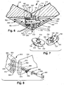
- Fig. 1 shows a clip and hook structure 100 in side view according to an illustrative embodiment of this invention.
- the hook assembly 100 (also termed herein the "clip") consists of a pair of portions 110 and 120-each defining a substantial mirror image of the other's outline perimeter shape.
- Each portion 110, 120 in this embodiment forms one half of an overall heart-shaped outline in this embodiment.
- Each clip portion 110, 120 defines a maximum width WH of approximately 50-60 mm in this embodiment and a height H of approximately 70-90 mm in this embodiment.
- the actual width and height are highly variable in alternate embodiments.
- the chosen width and height provides an interior region 130 when enclosed as shown that is sufficient to clear a handle, shoulder strap, or other carrying member of a bag, luggage piece or other hand/shoulder-carried item.
- the width WH also allows for a hook shape (as described below) that is sufficiently large to engage a variety of supporting surfaces.
- each portion 110 and 120 includes a resilient insert 144 and 146.
- the insert can be secured by a slot or keyway formed within each end 140 and 142, respectively.
- the body of each portion 110 and 120 can be constructed from a variety of materials with a variety of surface finishes. In one embodiment, the portions 110 and 120 are constructed from stainless steel with a matte or shiny finish. In alternate embodiments, the portions 110 and 120 can be hollow, in whole or in part. Alternatively, a durable plastic or other material can be employed, provided that is provides sufficient holding strength to perform the functions described herein. When formed from a metal, conventional casting techniques can be employed in one embodiment.
- the upper/free ends 140 and 142 have defined therebetween a small gap 150. The ends are unjoined with respect to each other and free of any clasps or other mechanisms in this embodiment. In alternate embodiments, as described below, a clasp or locking mechanism can be provided to secure the free ends together against inadvertent rotation out of the enclosed orientation.
- the clip 100 can be carried in the enclosed orientation (as shown in Fig. 1 ) around the carry handle 210 of a conventional handbag 220. In this orientation, it is relatively unobtrusive, and provides a decorative accent to the bag 220.
- the clip 100 can be carried on a belt loop, shoulder strap or any other enclosed or strap structure that generally prevents the clip from detaching inadvertently.
- the gap 150 is sufficiently narrow (for example a few millimeters or less) to prevent the handle 210 or another carrying member from passing therebetween.
- the opposing ends 160 and 162 of portions 110 and 120, respectively, are joined by a rotary joint 170 and embedded index assembly according to an embodiment of this invention.
- This index assembly will be described in further detail below.
- the index assembly allows the portions to be maintained in the enclosed orientation as shown in Fig. 1 , or with the application a suitable degree or rotational torque, rotated to a 180 degree position to form an S-shaped hook.
- the portions 110, 120 of the clip 100 have been rotated (double-curved arrow 310) 180-degrees about the rotary joint 170 from the enclosed heart-shaped orientation of Fig. 1 into an S-shape hook orientation.
- the resulting hook shows the upper portion 110 defining an inner perimeter 330 having an upward arch that ends in the resilient tip 144.
- This upper arch 330 allows the upper end to be hooked upon any acceptable supporting surface, such as a clothing hook, clothing hanger, chair back, door or bathroom stall top, wall peg/nail, or table/counter top without sliding free.
- the lower end of the hook, represented by portion 120 includes an inner perimeter 340 that projects below the tip 146.
- the inner perimeter 340 thereby provides a lower hook arch that can engage any acceptable carrying handle or other loop-like structure-and prevent that carrying handle/strap from sliding off.
- the projecting resilient tips define an extended hook end that aids in securing the hook around a given supporting surface.
- Fig. 4 when the clip 100 is rotated into the S-shaped hook orientation of Fig. 3 it can support the depicted carry handle 210 of the bag 220 at its lower hook end (portion 120), while the upper hook end (portion 110) engages the edge 410 of a table top 412 with the frictional tip 144 in engagement against the top 412.
- the hook securely maintains the bag with respect to the table top, in part, because the apex of each inner perimeter loop 330, 340, resides in a vertical line 430 with respect to gravity.
- the portions 440 and 450 of the portions 110 and 120, adjacent to the rotary joint 170 extend approximately along a line that passes at complimentary acute angles with respect to the vertical line 430.
- the two portions of the clip remain substantially in a common plane in the two opposed orientations (enclosed and open/S-hook) to aid in maintaining balance.
- the two (or more) portions can be formed with a more complex three-dimensional shape that deviates from a common plane, but still allows a substantially enclosed orientation as well and a hook that effectively balances items depending therefrom with respect to a supporting surface.
- the upper hook end (portion 110) of the clip can be secured to any acceptable supporting member while securely carrying the bag or another effect therebelow.
- Such supporting members can include, but are not limited to clothing hangers, coat hooks and pegs, chair backs, handlebars, automotive hand grips and door knobs.
- the portions can be divided asymmetrically on the overall shape and/o the overall shape can be asymmetrical.
- portion or portions should be taken broadly to include any division of the overall geometric shape of the clip with respect to the rotary joint.
- additional joints can be provided to create three or more portions of the overall clip, each allowing the clips shape to morph into a plurality of different arrangements.
- the rotary joint 170 provides two diametrically opposed (180-degree) locking positions, each of which can be selected by application by the user of a suitable level of rotational torque between the portions 110, 120 at the rotary joint 170.
- One locking position produces the enclosed orientation as shown in Fig. 1 and the other locking position produces the illustrative S-shaped hook orientation as shown in Fig. 3 .
- the opposing joint ends 160 and 162 of respective portions 110 and 120 are adapted to secure each of a pair of index inserts 510 and 520.
- the inserts 510 and 520 are adapted to interengage with each other.
- the insert 510 includes a pair of radially disposed male wedges (projections) 710 the opposing insert 520 includes a pair of confronting female grooves (detents) 720.
- the joint end 160 includes a cylindrical recess or orifice 530 of sufficient depth to house both of the inserts 510 and 520 in a stacked arrangement.
- the inner diameter DD of the recess 530 is approximately 8-9 millimeters in this embodiment.
- the outer diameter DI of each index insert 510, 520 is equal to, or less than, the recess diameter DD so that the inserts 510 and 520 can be nested within the recess 530 with little lateral/radial play.
- the male/wedge insert 510 includes a pair or rearwardly projecting flattened sides 740 that are adapted to engage interior flats/shoulders 540 within the recess 530.
- the opposing joint end 162 includes a slightly raised base 550 that includes flats adapted to engage corresponding flats 750 (shown in phantom in Fig. 7 ) within a hollow rear of the female/groove insert 520.
- the insert flats 740 and 750 in engagement with respective ends 160 and 162, thereby restrict rotation or the inserts 510 and 520 (respectively) relative to their portions 110 and 120.
- the inserts 510 and 520 are likewise rotated with respect to each other.
- the projections or wedges 710 and conforming detents or grooves 720 respectively project outwardly and inwardly approximately 0.3-0.4 millimeters.
- the overall depth of each insert is between approximately 1 and 3 millimeters. This dimension is highly variable.
- the inserts 510, 520 are constructed from a durable material that can reduce friction and wear generated by the rubbing of the wedges 710 against the surface of the female/groove insert 520 and the female insert's outer surface against the metallic surface of the recess 530.
- the material can be a high performance polymer such as polyoxymethylene (POM). Other materials are expressly contemplated.
- the wedges 710 and grooves or detents 720 flare radially outwardly.
- a variety of geometries can be used in alternate embodiments. In alternate embodiments, rather than exhibiting the depicted chiseled shape, the male and female index elements can be rounded over (see Fig. 8 , for example).
- each portion 110 and 120 adjacent to the ends 160 and 162 define a pair of concentric pockets 560 and 562, respectively each facing outwardly.
- the pockets 560, 562 provide for through-holes through which the spring and axle assembly of the joint can be inserted.
- the joint's axle is a machined screw 570 having an elongate cylindrical barrel section 572 and a threaded end 574 of smaller diameter.
- a series of cup-like Belleville steel washers 576 provide the spring assembly in this embodiment.
- a conventional coil compression spring can be employed (among other types of spring).
- the washers 576 seat within an outer cylindrical recess 630 formed within the pocket 562 (of portion 120).
- the washers 576 nested around the cylindrical shaft 572 portion of the axle screw 570. As shown, the washers 576 are oriented so that they cup against each other in opposing directions, thereby providing three discrete compression spring members as shown. In this embodiment, six washers are employed to create this spring shape. In alternate embodiments, the numbers of washers can be varied, along with their thickness and/or spring constant, to generate a different spring force.
- the axle screw's head 580 is of slightly larger diameter than the inner diameter of the washers 576, thereby allowing the head 680 to restrain the washers against a narrowed shoulder 640 within the cylindrical recess 630.
- the threaded end 574 of the axle screw 570 is tightened into a threaded wall 650 in the opposing end 160 of the portion 110.
- the forward shoulder 582 of the cylindrical shaft section 572 of the axle screw 570 helps to set and maintain the resting gap 660 between the two joint ends 160 and 162.
- the washers 576 are placed into spring compression to maintain the joint.
- the gap 660 is relatively small, so as to prevent play between the portions.
- the screw head 580 can include a Phillips or other appropriate drive head shape to allow it to be tightened to the appropriate torque.
- the axle screw 570 is constructed from a hard metal, such as steel, with a low-friction surface finish (nickel plating, for example).
- the axle screw 570 can have a diameter of approximately 3-5 millimeters.
- the pockets 560, 562 are capped by press-fitted plugs 564, 566, respectively.
- the plugs 564, 566 include outer cap surfaces 568, 569, respectively that conform to the surface contour of the surrounding portion 110, 120. In that manner, an appropriate surface coating or plating can be provided to each cap surface 568, 569 so that it visually blends with the surrounding surface finish.
- the plugs 562, 564 are constructed from ABS plastic. They can be friction fit and/or secured with an appropriate adhesive into the respective pockets.
- each end 140 and 142 includes a respective keyway 590 and 592 that receives a key structure 594 and 596 in each of the resilient tips 144 and 146, respectively.
- the tips can be secured by locking members, adhesives, or any other acceptable technique according to various embodiments of this invention.
- An acceptable material for forming the tips is a thermoplastic elastomer TPE. Other materials are expressly contemplated.
- the size and shape of the tip is highly variable, and can define a longer extension in alternate embodiments.
- Fig. 8 shows a rotary joint assembly 810 of an alternate embodiment of this invention. It can be assumed that the portions 820 and 830 of the structure have a perimeter shape that alternately defines an enclosed orientation and a 180-degree-opposed hook orientation in a manner described generally above. In this embodiment, the cross-section of each portion 820 and 830 defines a somewhat pinched-in (figure-eight) shape. This shape allows each end to receive an insert 840 and 850 within opposing figure-eight shaped recesses. The non-circular nature of the recess prevents rotation of the inserts with respect to their portions once they are seated.
- the insert 840 includes a pair of detents or holes 860 that are opposed by a pair of raised domes 870 in the opposing insert 850.
- An axle screw 880 having a threaded end 882 is provided similar to that described above. This screw enters through a cylindrical well 884 that also houses a series of Belleville washers 886, or another acceptable spring assembly.
- the threaded end 882 is received by a series of threads 888 provided in the end of the portion 820.
- the clip of Fig. 1 can be provided with respective insert-receiving recesses and corresponding inserts located on each of the opposing joint ends in the manner of Fig. 8 (rather than a single recess 530 on one end that receives both inserts 510, 520).
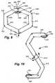
- the clip 900 includes a pair of portions 910 and 920 that collectively define an overall hexagon in the depicted enclosed orientation.
- the inner and outer perimeters are each substantially linear along each segment or side of the polygon, being separated by slightly rounded corners 930 and 932.
- a bottom rotary joint 940 allows rotation of the portions with respect to each other in a manner generally described above with respect to the embodiments of Figs. 1-8 .
- An opposing gap 950 is provided at the top free ends 960 and 962 of each portion 910 and 920, respectively.
- the clip 900 can be constructed from any durable material, such as stainless steel sing casting, machining or another acceptable technique. It should be assumed that the joint 940 is constructed in a manner similar to the spring-loaded indexing rotary joints described above, and are operated in a similar manner, by application of predetermined torque between the portions 910, 920.
- the top free ends 960 and 962 each carry an interior resilient projection 970 and 972, respectively. These projections, as described above, each act as a frictional member when engaging a table surface and also provide a hook end to prevent the hook ( Fig. 10 ) from sliding off of a supporting member.
- the free end 962 can include an upper extension 980 that acts as a locking mechanism. That is, the extension 980 projects upwardly so that it is accessible by a user's finger or thumb. It can be moved rearwardly (arrow 982) within a conforming slot to take it out of engagement with an opposing slot 984 that is formed within the opposing free end 960.
- the extension can be a spring-loaded metallic member on a pivot, or can be a resilient extension of the resilient projection 970.
- the locking mechanism 982 is optional, as the indexing function of the joint 940 allows movement between the enclosed orientation shown in Fig. 9 and the 180-degree opposed orientation shown in Fig. 10 .
- the opposed orientation in Fig. 10 in which the clip 900 forms an S-shaped hook, is defined by applying torque between the two portions 910 and 920 and rotating (double arrow 1010) the portions with respect to each other until a tactile click is felt when the hook has achieved its final position.
- the free ends can include magnetically attractive structures (not shown) as a locking mechanism. Such a structure can ensure that the free ends require additional torque to unlock the two joined portions.
- locking mechanism in association with the free ends shall include such mechanical and magnetic arrangements.
- the illustrative clip 900 includes an inner perimeter shape that allows it to perform a particular task as an added accessory.
- a bottle 1110 having a conventional crimp cap 1112 has been inserted into the inner perimeter at the central polygon segment 1120 of the portion 910.
- the inner surface of the segment 1120 (and potentially the opposing inner surface 1130) is shaped and sized to engage a bottle cap as shown.
- the inner corners (930) of the leg 1120 are sized to provide appropriate clearance for the particular diameter of a conventional bottle end and cap.
- the clip 900 is capable of removing the crimp cap 1112.
- a clip of this style and type can be worn on a belt loop, placed on a bag or briefcase, attached to a cooler, or otherwise carried with in the enclosed orientation.
- any of the clips herein can be provided with a decorative surface shape that is appropriate to the style and purpose of that clip.
- a clip 1200 that is functionally and structurally similar to those described above, includes a series of machined through-cuts or deep indentations 1210, 1220, and 1230 within each segment of each portion.
- the lower section adjacent to the joint 1240 includes in-filled areas 1250 that house the spring and screw-axle mechanism of the rotary joint.
- any of the clips described herein can be used in a variety of roles, such as a clothing accessory or piece of functional jewelry.
- the size of the clip portions and resulting enclosed area of the inner perimeter of the clip according to various embodiments is highly variable.
- the clip can be sized to be worn on a necklace, or around an item (e.g. a belt loop) that is smaller than a bag or purse strap.
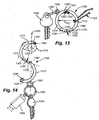
- Figs. 13 and 14 show an accessory clip 1300 formed with a circular perimeter shape (another exemplary shape out of the myriad of possible shapes contemplated herein) with an inner diameter DC that may be 1 inch, more or less.
- Such a shape and size is suitable to be worn around a neck chain (such as exemplary chain 1302), or on a button hole or belt loop (among other locations).
- This embodiment includes a pair of opposed portions 1310, 1312 that again define mirror image halves (semi-circles) with a rotary joint 1320 joining two ends 1330, 1332 thereof and a pair of opposing unjoined ends 1340, 1342 that confront each other with a minimal gap that prevents slippage of the clip in the enclosed orientation ( Fig, 13 ) from passing through a supporting item, such as a jewelry chain.
- a locking member optionally provided between the two free ends 1340, 1342, such as that shown in Fig. 9 .
- the rotary joint 1320 includes an index assembly. The index can be constructed as a smaller version of that described above in the embodiment of Figs 1-8 .
- the joint 1320 allows the opposing portions 1310, 1312 rotates about an axis (dashed line 1370) to rotate between the enclosed orientation of Fig. 13 and an S-hook-shaped orientation as shown in Fig. 14 .
- the axle and spring assembly can be inserted via external cavities that are covered by plugs 1380, 1882 in a manner described above.
- the resilient tips 1350, 1352 on each of the respective free ends 1340, 1342 are extended radially inwardly to provide an enhanced hook surface, and thereby provide further stability when the clip 1300 is deployed in hook form to depend from a support surface (peg 1410) as shown in Fig. 14 .
- this embodiment includes an additional accessory structure.
- This structure comprises a soldered/welded-on (or otherwise adhered) loop 1390, mounted along the exterior surface/perimeter of the portion 1310.
- the loop 1390 in this embodiment supports a key ring 1392 with exemplary key 1394.
- a variety of other items can be attached via the loop 1390, such as the exemplary computer memory stick 1396 (shown in phantom).
- accessory structure should be taken broadly to include a variety of attached structures that enable the interconnection of other items to the clip.
- the accessory structure/loop 1390 in this embodiment is located on the perimeter of the portion 1340 at a location that causes the attached accessory (key 1394) to depend along a vertical line (dashed line 1420) that is parallel to gravity and rind through the upper arch of the portion 1312 in the depicted S-hook orientation.
- the accessory is positioned so as to maintain the balance of the hook when attached to supporting surface (exemplary peg 1410).
- the loop 1390 (or another accessory structure) can be used to attach one or more other types of accessories.
- Such possible accessories include, but are not limited to, cellular telephones, personal digital assistants (PDAs), pepper spray canisters, flashlights, pen knives, nail clippers and/or grooming aids, etc.
- the depicted clip 1300 can be used to carry accessories directly upon one of the portions while the other portion depends from a supporting surface.
- the user can deploy the hook on a shower stall peg, and place jewelry, watches, etc. on the opposing portion while showering.
- the clip can be carried on a gym bag and used in a locker to hang clothes or to support a towel from a shower curtain rod, etc. while showering.
- a myriad of possible applications are contemplated.
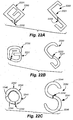
- Fig. 15A is a perspective view of an illustrative bracelet 1500 in an enclosed orientation that can be torsionally converted to an open S-hook configuration.
- the body of the bracelet 1502 is arranged to enclose a wrist or ankle and features a J-shaped curve 1504 at one of the free ends.
- the bracelet 1500 features a rotary joint 1506 that is operated by application of sufficient rotary torque.
- the bracelet 1500 is composed of a metal, such as gold-plated metallic alloy, silver-plated metallic alloy, platinum-plated metallic alloy or any other metal that provides strength and comfort to the wearer.
- the surface of the bracelet can be decorated with a variety of inscribed or embossed designs and can be jeweled with various combinations and types of jewels.
- the overall shape of the exemplary bracelet as depicted enclosed orientation in Fig. 15A The bracelet lies generally within a common plane ("coplanar"), with a J-shaped curve 1504 defined at one free end.
- the bracelet is coplanar in that the free ends confront each other to form the closure.
- the J-shaped curved end in fact projects outside the plane to provide an added ornamental effect. It is contemplated that the shape can be asymmetrical, serpentine, twisted, or other shapes.
- Fig. 15B is a top view 1510 of the exemplary bracelet described in Fig. 15A . This view further shows the profile of the J-shaped curve 1504, which can be viewed as serving both the function of a decorative accent and as the lower hook when in the open S-shaped hook orientation, as described more fully below.
- Fig. 15C is a side view 1520 of the exemplary bracelet described in Fig.15A .
- Fig. 15D is an end view 1530 of the exemplary bracelet described in Fig. 15A .
- the end caps 1532 and 1534 cover the access recesses of the rotary joint assembly (described more fully below).
- Fig. 16 is a side view of the exemplary bracelet described in Fig. 15A in the open S-hook orientation 1600.
- the user has removed the body of the bracelet 1502 from their body and with their hands has applied a counterpoised torsional force to the upper portion 1524 and the lower portion 1522, causing them to rotate around the rotary joint 1506, until the rotary joint mechanism has locked the body of the bracelet 1502 into the open S-hook orientation 1600.
- the clip and hook are now configured to facilitate the suspension of bags and hand/shoulder-carried items, as set forth above.
- the rotary joint mechanism assembly 1702 is shown in Fig. 17 in cross-section 1700.
- the functionality of the exemplary bracelet rotary joint mechanism assembly 1702 is similar to the mechanism set forth in Figure 7 .
- the lower portion 1522 is joined to the upper portion 1524 at the rotary joint 1506.
- the opposing joint ends 1704 and 1706 of the respective portions 1522 and 1524 are adapted to secure each of a pair of index inserts 1708 and 1710.
- the inserts 1708 and 1710 are adapted to interengage with each other.
- the insert 510 includes a pair of radially disposed male wedges (projections) similar to 710 above and the opposing insert 1712 includes a pair of confronting female grooves (detents) similar to 720 above.
- the opposing joint ends 1704 and 1706 include cylindrical pockets, respectively 1712 and 1714.
- the inner diameter EE of pocket 1712 is approximately 8-9 millimeters in this embodiment.
- the inner diameter FF of pocket 1714 is approximately 8-9 millimeters in this embodiment.
- the inserts 1708, 1710 are seated within inscribed grooves, respectively 1716 and 1718, within the opposing joint ends 1704, 1706, with little lateral/radial play.
- the inserts 1708, 1710 are likewise rotated with respect to each other.
- the overall depth of each insert is between approximately 1 and 3 millimeters. This dimension is highly variable.
- the inserts 1708, 1710 are constructed from a durable material that can reduce friction and wear generated by the rubbing of the wedges against the surface of the female/groove insert and the female insert's outer surface against the respective joint ends 1704, 1706.
- the material can be a high performance polymer such as polyoxymethylene (POM). Other materials are expressly contemplated.
- the male and female index elements can be rounded over (see Fig. 8 , for example).
- each respective free ends 1522, 1524 adjacent to the joint ends 1704 and 1706 define a pair of concentric pockets 1712, 1714, respectively each facing outwardly.
- the pockets 1712,1714 provide for through-holes through which the spring and axle assembly of the joint can be inserted.
- the joint's axle is a machined axle shaft pin 1720 having an elongate cylindrical barrel section 1722, end 1724 of the same diameter and head end 1726 of larger diameter.
- a series of cup-like Belleville steel washers 1730 provide the spring assembly in this embodiment.
- a conventional coil compression spring can be employed (among other types of spring).
- the washers 1730 seat at the respective inner walls 1732 of the respective inner walls of concentric pockets 1712, 1714.
- the washers 1730 are held in place by retaining washers 1734.
- the washers 1730 nested around the cylindrical shaft 1740 portion of the axle shaft pin 1720. As shown, the washers 1730 are oriented so that they cup against each other in opposing directions, thereby providing two discrete compression spring members as shown.
- the numbers of washers can be varied, along with their thickness and/or spring constant, to generate a different spring force.
- the axle shaft pin head end 1726 is of slightly larger diameter than the inner diameter of the washers 1730, thereby allowing the head end 1726 to restrain the washers 1730 against the inner wall 1732 of the joint end 1704 within the pocket 1712.
- the end 1724 of the axle shaft pin 1720 is inscribed with a rectangular groove 1744 that is fitting with a removable locking washer 1742 Or another axial locking structure) to restrain the Belleville washers against the inner wall 1732 of the joint end 1704 within the pocket 1712.
- the combined tension of the locking washer 1742 and washers 1730 helps to set and maintain the resting gap 1750 between the two joint ends 1704 and 1706. When assembled, the washers 1730 are placed into spring compression to maintain the joint.
- the axle shaft pin 1720 is constructed from a hard metal, such as steel, with a low-friction surface finish (nickel plating, for example).
- the axle shaft pin 1720 can have a diameter of approximately 3-5 millimeters.
- the pockets 1712, 1714 are capped by press-fitted plugs 1532, 1534, respectively.
- the plugs 1532, 1534 include outer cap surfaces 1752, 1754, respectively that conform to the surface contour of the surrounding free end 1522, 1524. In that manner, an appropriate surface coating or plating can be provided to each cap surface 1752, 1754 so that it visually blends with the surrounding surface finish.
- the plugs 1532, 1534 are constructed from ABS plastic. They can be friction fit and/or secured with an appropriate adhesive into the respective pockets.
- Figs. 22A to 22F are alternative shapes for the clip and hook structures.
- Fig. 22A is an angular G-shaped clip 2201 with a rotary joint 2202 shown in an enclosed orientation 2200 and open orientation 2210 that can be moved torsionally into an angular S-shaped hook in the open orientation 2210 for the suspension of handbags and other articles from a surface.
- Fig. 22B is a rounded G-shaped clip 2221 with a rotary joint 2222 shown in an enclosed orientation 2220 and open orientation 2230 that can be moved torsionally into an S-shaped hook in the open orientation 2230, likewise for the suspension of handbags and other articles from a surface.
- Fig. 22C is an O-shaped clip 2241 with a rotary joint 2242 shown in an enclosed orientation 2240 and open orientation 2250 that can be moved torsionally into an S-shaped hook in the open orientation 2250 for the suspension of handbags and other articles from a surface.
- the O-shaped clip 2241 defines an overlap 2242 of the portions 2244, 2246 adjacent to their free ends.
- This overlap 2242 requires that the wedge and detent wells (not shown) of the rotary joint 2242 be rotationally offset, so that the portions reside in non-coplanar orientations in the depicted closed orientation.
- the portions can be formed with bends that place at least the free ends in non-coplanar positions with respect to each other when the joint is locked in the enclosed orientation.
- Complete 360-degree rotation of the portions 2244, 2246 is impeded in this embodiment because of the overlap 2242, and typically the enclosed orientation is locked in only one of two possible rotations.
- Fig. 22D is a coiled clip 2271 with a rotary joint 2272 in an enclosed orientation 2270 and open orientation 2275 that can be moved torsionally into an S-shaped hook in the open orientation 2275 for the suspension of handbags and other articles from a surface.
- the coil In its closed orientation, the coil defines an overlap 2274 relative to the coiled clip 2271 of the portions 2276, 2278 and permits complete rotation of the portions 2276, 2278.
- Fig. 23E is an overlapped diamond-shaped clip 2281 with a rotary joint 2282 in an enclosed orientation 2280 and open orientation 2285 that can be moved torsionally into an angular S-shaped hook in the open orientation 2285 for the suspension of handbags and other articles from a surface.
- the diamond-shaped clip 2281 defines an overlap 2284 of the portions 2286, 2288 adjacent to their free ends. This overlap 2284 requires that the wedge and detent wells (not shown) of the rotary joint 2242 be offset. Complete rotation of the portions 2286, 2288 is not possible because of the overlap 2284.
- Fig. 23F is an overlapped tear-shaped clip 2290 with a rotary joint 2292 in an enclosed orientation 2290 and open orientation 2295 that can be moved torsionally into an angular hook (for, example an S-shaped hook) in an open orientation 2295 for the suspension of handbags and other articles from a surface.
- the diamond-shaped clip 2291 defines an overlap 2294 of the portions 2296, 2298 adjacent to their free ends. Complete rotation of the portions 2296, 2298 is not possible because of the overlap 2294.
- hook assembly of the various embodiments of this invention is a highly useful and yet aesthetically pleasing device that can be used by men and women alike. It lends itself to a variety of unique shapes and designs and can be constructed from a variety of materials, or combinations of materials.
- any of the embodiments herein can include opposing wedges and detents, with at least one wedge and at least one detent on each opposing surface of the joint.
- the rotary joint is constructed using a screw-axle and spring washers in this embodiment, a variety of spring assemblies that allow a pair of opposing detent pieces to be biased toward each other can be employed.
- inserts are used for the detents and projections in the rotary joint of the hook assembly of this invention
- such members can be formed directly on the surfaces of the two confronting ends of the portions.
- the spring mechanism is then applied directly between the portions without intervening inserts.
- the term "inserts” should be taken broadly to include such a directly-confronting surface arrangement each clip portion's joint end.
- an indexing mechanism based upon confronting projections and detents is shown, a variety of such projections and detents are expressly contemplated, such as a spring-loaded ball, and detent structure located between an outer cylinder on one clip portion and a nested, coaxial inner cylinder on the other clip portion.
- the overall structure can include multiple joints that fundamentally define parts that enable an opened and closed orientation (for example, a portion can include a portion that has a plurality or rotational joints). Accordingly, the embodiments are meant to be taken only by way of example, and not to otherwise limit the scope of this invention.
Landscapes
- Engineering & Computer Science (AREA)
- Mechanical Engineering (AREA)
- Purses, Travelling Bags, Baskets, Or Suitcases (AREA)
- Supports Or Holders For Household Use (AREA)
- Hooks, Suction Cups, And Attachment By Adhesive Means (AREA)
Claims (15)
- Ensemble de crochet (100, 900), comprenant :une première partie (110, 820, 910) et une deuxième partie (120, 830, 920), chaque partie, la première partie et la deuxième partie, étant reliée de manière rotative au niveau d'un joint articulé rotatif (170, 820, 940), au niveau d'extrémités de liaison respectives (160, 162) de celui-ci, la première partie et la deuxième partie définissant chacune une forme de périmètre (330, 340), dans lequel la première partie et la deuxième partie définissent (a) une orientation renfermée lorsque le joint articulé se trouve dans une première position de rotation, les extrémités libres respectives de la première partie et de la deuxième partie se trouvant dans une relation de confrontation, de sorte à établir une forme interne renfermée (130), et (b) une orientation de crochet lorsque le joint articulé se trouve dans une deuxième position de rotation, éloignée dans le sens de la rotation de la première position de rotation ; etdans lequel le joint articulé englobe un ensemble d'indexage retenant sélectivement la première partie et la deuxième partie dans chaque position, la première position de rotation et la deuxième position de rotation, avec un déplacement entre elles par suite de l'application d'un couple de rotation prédéterminé au niveau du joint articulé ;dans lequel l'ensemble d'indexage englobe un essieu (570, 880), une première surface d'indexage (160) interconnectée à la première partie, comportant au moins une saillie mâle (710), et une deuxième surface d'indexage (162), interconnectée à la deuxième partie, comportant au moins un cliquet femelle (720), et un ensemble de ressort (576) poussant par déplacement la première surface d'indexage vers la deuxième surface d'indexage, et permettant le déplacement de la première surface d'indexage à l'écart de la deuxième surface d'indexage, en présence de la compression exercée par l'ensemble de ressort, caractérisé en ce que la première surface d'indexage (160) et la deuxième surface d'indexage (162) sont chacune positionnées de manière rotative sur l'essieu (570, 880).
- Ensemble de crochet selon la revendication 1, dans lequel chaque position, la première position de rotation et la deuxième position de rotation, est éloignée dans le sens de la rotation d'environ 180 degrés l'une de l'autre.
- Ensemble de crochet selon la revendication 1, dans lequel la première surface d'indexage (160) comprend un premier insert (510, 840) monté sur la première partie, la deuxième surface d'indexage (162) comprenant un deuxième insert (520, 850) monté sur la deuxième partie.
- Ensemble de crochet selon la revendication 1, dans lequel l'ensemble de ressort comprend plusieurs rondelles Belleville (576, 886) agencées par paires, courbées les unes contre les autres.
- Ensemble de crochet selon la revendication 4, dans lequel les paires de rondelles Belleville peuvent être montées les unes par rapport aux autres sur chacune des extrémités opposées de l'essieu.
- Ensemble de crochet selon la revendication 4, dans lequel l'essieu comprend au moins un des éléments suivants : (a) une vis à filet (570) comportant une section d'arbre cylindrique (572), sur laquelle les rondelles Belleville (576) sont montées, et (b) un arbre définissant un cordon sur une première extrémité de celle-ci et un clip amovible sur une deuxième extrémité de celle-ci.
- Ensemble de crochet selon la revendication 1, dans lequel l'essieu et l'ensemble de ressort sont montés dans des poches respectives (560, 562) agencées de manière concentrique sur chaque partie, la première partie et la deuxième partie, et dans lequel chacune des poches respectives peut englober un obturateur (564, 566) comportant une surface de capuchon (568, 569) adaptée respectivement à une forme de surface adjacente de la première partie (110) et la deuxième partie (120).
- Ensemble de crochet selon la revendication 1, dans lequel :les extrémités libres englobent chacune respectivement une pointe élastique (144, 146) ; etchaque pointe élastique peut déborder vers l'intérieur pour former une extrémité de crochet étendue par rapport à une extrémité respective des extrémités libres.
- Ensemble de crochet selon la revendication 1, dans lequel la première partie (110) et la deuxième partie (120) définissent chacune une forme de périmètre, définissant dans l'orientation renfermée une forme en coeur, et dans lequel chaque partie, la première partie et la deuxième partie, peut définir des moitiés d'image symétrique de la forme en coeur.
- Ensemble de crochet selon la revendication 1, dans lequel la première partie (910) et la deuxième partie (920) définissent chacune une forme de périmètre, définissant dans l'orientation renfermée au moins une partie d'une forme en polygone.
- Ensemble de crochet selon la revendication 1, dans lequel la première partie et la deuxième partie définissent chacune une forme de périmètre, définissant dans l'orientation renfermée au moins une partie d'une forme circulaire.
- Ensemble de crochet selon la revendication 1, dans lequel au moins une partie, la première partie ou la deuxième partie, englobe un périmètre interne (1120), construit et agencé de sorte à définir une partie d'engagement d'une capsule de bouteille d'un décapsuleur.
- Ensemble de crochet selon la revendication 1, dans lequel au moins une partie, la première partie ou la deuxième partie, englobe une structure accessoire qui y est montée, assurant une fonction prédéterminée, et dans lequel la structure accessoire peut comprendre un ensemble de fixation d'un article fixé sur un bord d'une partie, la première partie ou la deuxième partie, en un emplacement permettant le maintien en équilibre de l'autre partie, la première partie ou la deuxième partie, sur une surface de support, avec un article qui y est fixé, lorsque la première partie et la deuxième partie sont orientées dans une orientation de crochet.
- Ensemble de crochet selon la revendication 1, dans lequel :la première partie et la deuxième partie définissent un périmètre intérieur, dimensionné et agencé, dans l'orientation renfermée, de sorte à s'adapter autour d'une sangle d'un sac porté à la main (220) ; oules extrémités libres respectives de la première partie et de la deuxième partie se chevauchent mutuellement dans l'orientation renfermée.
- Ensemble de crochet selon la revendication 1, dans lequel la première partie et la deuxième partie sont construites et agencées de sorte à définir une pièce de joaillerie ferme (1500) dans l'orientation renfermée et permettent le retrait de la pièce de joaillerie dans la deuxième orientation.
Applications Claiming Priority (3)
| Application Number | Priority Date | Filing Date | Title |
|---|---|---|---|
| US10110408P | 2008-09-29 | 2008-09-29 | |
| US12/568,663 US8162276B2 (en) | 2008-09-29 | 2009-09-28 | Rotary joint assembly and combination clip-hook and jewelry piece employing the same |
| PCT/US2009/058761 WO2010037091A1 (fr) | 2008-09-29 | 2009-09-29 | Ensemble joint tournant, combinaison crochet-attache et bijou utilisant ledit joint |
Publications (3)
| Publication Number | Publication Date |
|---|---|
| EP2350476A1 EP2350476A1 (fr) | 2011-08-03 |
| EP2350476A4 EP2350476A4 (fr) | 2013-02-13 |
| EP2350476B1 true EP2350476B1 (fr) | 2016-02-17 |
Family
ID=42056355
Family Applications (1)
| Application Number | Title | Priority Date | Filing Date |
|---|---|---|---|
| EP09817031.9A Active EP2350476B1 (fr) | 2008-09-29 | 2009-09-29 | Ensemble crochet et bijou utilisant ledit ensemble |
Country Status (6)
| Country | Link |
|---|---|
| US (1) | US8162276B2 (fr) |
| EP (1) | EP2350476B1 (fr) |
| JP (1) | JP5602744B2 (fr) |
| CN (1) | CN102232150B (fr) |
| HK (1) | HK1160675A1 (fr) |
| WO (1) | WO2010037091A1 (fr) |
Families Citing this family (42)
| Publication number | Priority date | Publication date | Assignee | Title |
|---|---|---|---|---|
| US9131758B2 (en) * | 2004-08-17 | 2015-09-15 | The Finding Ip Holding Company Llc | Key locator with a container |
| US20110297632A1 (en) * | 2007-04-12 | 2011-12-08 | EMSA Sales Corporation | Inside wall mounted hanging rods |
| NL1035777C2 (nl) * | 2008-07-31 | 2010-02-02 | Wilhelmus Henricus Albertus Van Maasakkers | Ophangsysteem en werkwijze. |
| US9273718B2 (en) * | 2008-09-29 | 2016-03-01 | Clipsy, Inc. | Rotary joint assembly and combination clip-hook and jewelry piece employing the same |
| US9474336B2 (en) * | 2008-09-29 | 2016-10-25 | Clipsy, Llc | Rotary joint assembly and combination clip-hook and jewelry piece employing the same |
| US20100155555A1 (en) * | 2008-12-24 | 2010-06-24 | Alan Shih | Apparatus for Attaching an External Object to a Portable Computer |
| US20100282378A1 (en) * | 2009-05-11 | 2010-11-11 | Frank Charles Scozzafava | Handbag with interchangeable components |
| US20110010903A1 (en) * | 2009-07-16 | 2011-01-20 | Starbuck Michele D | Article hanger |
| US8534626B1 (en) * | 2010-01-19 | 2013-09-17 | Brica, Inc. | Dual-configuration hanger |
| US8746640B2 (en) * | 2010-01-31 | 2014-06-10 | Simon Broadley | Hanger hook |
| US9089125B1 (en) * | 2010-04-07 | 2015-07-28 | Curtis D. Fast | Leveling hunting stand system |
| US20120272427A1 (en) * | 2010-05-27 | 2012-11-01 | Scozzafava Frank C | Articles of Clothing with Interchangeable Components |
| WO2011154055A1 (fr) * | 2010-06-11 | 2011-12-15 | Sbaraglia, Jessica | Porte-sac de table transformable en bracelet |
| JP3166666U (ja) * | 2010-11-23 | 2011-03-17 | 八幡化成株式会社 | バッグハンガー |
| US20130037672A1 (en) * | 2011-08-11 | 2013-02-14 | Roy C. Sanchez | Twist Tie Hat Hook Headrest Hanger |
| US8556095B1 (en) | 2011-10-06 | 2013-10-15 | Sawako Yamaguchi | Threaded bottle cap having magnetically detachable decoration |
| AU2013224626A1 (en) * | 2012-02-20 | 2015-07-23 | Global Shopping Network Pty Ltd | A hook for use with a handbag to locate articles |
| EP2674053A1 (fr) * | 2012-06-15 | 2013-12-18 | Dominic Guerrini | Anneau de clé |
| USD708446S1 (en) * | 2013-03-01 | 2014-07-08 | Spectrum Diversified Designs, Inc. | Closet rod hook |
| JP2016513555A (ja) * | 2013-03-15 | 2016-05-16 | クリプスィ エルエルシーClipsy, Llc | 回転継手アセンブリ並びにクリップ・フックの組合せ及びこの組合せを採用した宝飾品 |
| US20140317887A1 (en) * | 2013-03-15 | 2014-10-30 | Albert N. Santilli | Napkin/Purse Holder |
| JP6233770B2 (ja) * | 2013-07-02 | 2017-11-22 | 厚樹 宮本 | 磁気式環状物品保持具 |
| US9080715B2 (en) | 2013-10-02 | 2015-07-14 | Steelcase Inc. | Support device for suspending an article from a horizontal object |
| US9775414B2 (en) * | 2014-11-05 | 2017-10-03 | Htc Corporation | Portable electronic device |
| US20170086554A1 (en) * | 2015-09-30 | 2017-03-30 | Yolanda Felix | Purse Securing Device |
| ITUB20159516A1 (it) * | 2015-12-29 | 2017-06-29 | Lino Manfrotto Co S P A | Supporto per apparecchiature elettroniche portatili |
| USD800962S1 (en) * | 2016-04-21 | 2017-10-24 | Paula Joseph | Eyebrow shaping guide |
| WO2018058009A1 (fr) | 2016-09-26 | 2018-03-29 | The Procter & Gamble Company | Forme galénique à libération prolongée |
| USD873701S1 (en) * | 2017-02-23 | 2020-01-28 | Arthrology Consulting, Llc | Jewelry piece |
| US10016077B1 (en) * | 2017-06-23 | 2018-07-10 | Raymond M. Carney | Bracket for wall mounting |
| EP3819506B1 (fr) * | 2018-07-03 | 2023-03-15 | Vie International Group Co., Ltd. | Crochet d'élément de suspension de bagage |
| CN109168469A (zh) * | 2018-09-03 | 2019-01-11 | 新绛县益农播种机械有限公司 | 一种播种机用四连杆机构 |
| US10578148B1 (en) | 2018-10-17 | 2020-03-03 | Ford Global Technologies, Llc | Carabiner including a removable gate section carrying a bottle opener feature |
| US10793212B2 (en) * | 2018-12-12 | 2020-10-06 | Thomas Peter Joe | Bicycle hanger for hung storage of a bicycle by its seat and seat post |
| WO2020205054A1 (fr) * | 2019-04-03 | 2020-10-08 | Suterra, Llc | Dispositif de soufflerie |
| JP1661291S (fr) * | 2019-09-04 | 2020-06-08 | ||
| KR102272923B1 (ko) * | 2019-09-04 | 2021-07-05 | 류안수 | 휴대용 가방 걸이 |
| USD897881S1 (en) * | 2019-10-24 | 2020-10-06 | Nora L Ashton | Combined bracelet and purse hook |
| USD964205S1 (en) * | 2020-11-24 | 2022-09-20 | Richard Winters Collins | Decorative element for jewelry |
| CN114635133B (zh) * | 2022-02-17 | 2024-03-29 | 临沭佳柳工艺品有限公司 | 工艺品表面全面镀膜及检测设备 |
| US20230303376A1 (en) * | 2022-03-24 | 2023-09-28 | Jade M Brown | Serviceable crown cap removing device and method thereof |
| USD1036134S1 (en) | 2022-05-24 | 2024-07-23 | Davinci Ii Csj, Llc | Hanger hook |
Family Cites Families (46)
| Publication number | Priority date | Publication date | Assignee | Title |
|---|---|---|---|---|
| US477270A (en) | 1892-06-21 | Hook-rack | ||
| US449103A (en) * | 1891-03-31 | Carl bachem | ||
| DE7908460U1 (de) | 1979-07-05 | Kamps, Fritz, 7147 Hochdorf | Sicherheitshaken | |
| US419141A (en) * | 1890-01-07 | levi m | ||
| US252441A (en) * | 1882-01-17 | Bracelet and clasp | ||
| US808322A (en) | 1905-05-02 | 1905-12-26 | Bates & Bacon | Bracelet. |
| US813755A (en) | 1905-07-24 | 1906-02-27 | Bates & Bacon | Bracelet. |
| US843243A (en) | 1906-06-30 | 1907-02-05 | S O Bigney And Company | Bracelet. |
| US843195A (en) | 1906-09-26 | 1907-02-05 | Bates & Bacon | Bracelet. |
| US1132414A (en) * | 1914-03-28 | 1915-03-16 | John Tomas White | Coat-hook. |
| US2555890A (en) | 1949-06-29 | 1951-06-05 | Hazel M Korth | Bracelet and utility holder |
| US2692108A (en) | 1950-06-30 | 1954-10-19 | Neivert Harry | Combined handbag hanger and glove holder |
| US2842822A (en) | 1955-10-10 | 1958-07-15 | William F Bennett | Collapsible utility hook |
| US2997182A (en) | 1960-06-21 | 1961-08-22 | Lewis | Drip dry shower rack |
| US3630475A (en) | 1969-12-15 | 1971-12-28 | James H Barry | Invertible hanger carrier |
| US3860210A (en) | 1973-08-13 | 1975-01-14 | Said Berardinelli By Said Goul | Handbag holder |
| USD244910S (en) | 1976-01-14 | 1977-07-05 | Coats & Clark, Inc. | Hook |
| US4194714A (en) | 1976-03-15 | 1980-03-25 | Prima International | Foldable purse hanger and whistle |
| USD250003S (en) | 1976-08-25 | 1978-10-24 | Osmos Plast Aktiebolag | Suspension hook |
| US4210302A (en) | 1979-04-06 | 1980-07-01 | Serkez Alvin A | Handbag holder |
| JPS5757219Y2 (fr) * | 1978-09-13 | 1982-12-08 | ||
| JPS5630310Y2 (fr) * | 1978-12-16 | 1981-07-18 | ||
| USD271385S (en) | 1980-10-16 | 1983-11-15 | Gyora Novak | Sculpture or the like |
| JPS6037621U (ja) * | 1983-08-24 | 1985-03-15 | 川一商事株式会社 | 吊下げ具 |
| JPH0344569Y2 (fr) * | 1984-12-21 | 1991-09-19 | ||
| US4792253A (en) | 1986-10-27 | 1988-12-20 | Jacobson Ralph S | Binder ring having slip-on folio stops |
| JPS63128870U (fr) * | 1987-02-17 | 1988-08-23 | ||
| JPH0542262Y2 (fr) * | 1988-03-30 | 1993-10-25 | ||
| USD314864S (en) | 1988-09-28 | 1991-02-26 | Creed Kenny D | Table top hook for purse or similar article |
| US5094417A (en) | 1990-12-03 | 1992-03-10 | Creed Kenny D | Handbag adaptable support |
| JPH0667917U (ja) * | 1993-02-15 | 1994-09-22 | 株式会社ニッサチェイン | 組み合わせ式吊り具 |
| USD447932S1 (en) | 2000-10-23 | 2001-09-18 | Bison Designs, L.L.C. | Heart shaped carabiner |
| US6530548B2 (en) | 2001-06-18 | 2003-03-11 | Angela Pizzirusso | Technique for hanging strap from edge of furniture |
| CN1260072C (zh) | 2002-07-19 | 2006-06-21 | 国际文具制造厂有限公司 | 环形活页夹机构 |
| US7097223B1 (en) * | 2003-04-24 | 2006-08-29 | Bradford Mark P | Shopping bag handle |
| USD489249S1 (en) | 2003-06-23 | 2004-05-04 | Sean A. Moore | Shower curtain hook |
| US8371546B2 (en) | 2004-01-23 | 2013-02-12 | Shelly Lenna Bauerly | Purse hanger |
| USD515450S1 (en) | 2004-10-01 | 2006-02-21 | Mary Ann Schiesl-Griesinger | Jewelry bracelet |
| US20060108497A1 (en) * | 2004-11-19 | 2006-05-25 | Miranda Ana C C | Holding device |
| US20060108496A1 (en) | 2004-11-19 | 2006-05-25 | Miranda Ana Claudia C | Holding device |
| USD550113S1 (en) | 2005-06-16 | 2007-09-04 | Oesterbaek Kenneth | Jewelry |
| USD542171S1 (en) | 2005-11-17 | 2007-05-08 | America's Love Doctor Llc | Jewelry |
| US20080001041A1 (en) * | 2006-06-15 | 2008-01-03 | Guillermo Ascanio | Multi-use bag carrier, or loose/disparate item consolidator |
| US7644900B2 (en) | 2006-08-15 | 2010-01-12 | Luxe Link, Llc | Portable hanger for purse |
| USD569714S1 (en) | 2006-08-30 | 2008-05-27 | Fusion Brands Incorporated | Combined hook and holder |
| US7837171B1 (en) * | 2009-08-07 | 2010-11-23 | Yoko Otake | Purse hanger with extendible shelf |
-
2009
- 2009-09-28 US US12/568,663 patent/US8162276B2/en active Active
- 2009-09-29 JP JP2011529346A patent/JP5602744B2/ja active Active
- 2009-09-29 CN CN200980147854XA patent/CN102232150B/zh active Active
- 2009-09-29 EP EP09817031.9A patent/EP2350476B1/fr active Active
- 2009-09-29 WO PCT/US2009/058761 patent/WO2010037091A1/fr active Application Filing
-
2012
- 2012-02-03 HK HK12101019.1A patent/HK1160675A1/zh unknown
Also Published As
| Publication number | Publication date |
|---|---|
| US20100078541A1 (en) | 2010-04-01 |
| HK1160675A1 (zh) | 2012-08-10 |
| CN102232150B (zh) | 2013-07-24 |
| JP2012504217A (ja) | 2012-02-16 |
| EP2350476A1 (fr) | 2011-08-03 |
| JP5602744B2 (ja) | 2014-10-08 |
| CN102232150A (zh) | 2011-11-02 |
| US8162276B2 (en) | 2012-04-24 |
| WO2010037091A1 (fr) | 2010-04-01 |
| EP2350476A4 (fr) | 2013-02-13 |
Similar Documents
| Publication | Publication Date | Title |
|---|---|---|
| EP2350476B1 (fr) | Ensemble crochet et bijou utilisant ledit ensemble | |
| US11015640B2 (en) | Rotary joint assembly and combination clip-hook and jewelry piece employing the rotary joint assembly | |
| US9474336B2 (en) | Rotary joint assembly and combination clip-hook and jewelry piece employing the same | |
| EP2967199B1 (fr) | Structure renfermant amovible | |
| US11744333B2 (en) | Segmented attachment device | |
| RU2519917C2 (ru) | Дамская сумочка (варианты) и способ ее подгонки | |
| US20040195484A1 (en) | Accessory hanger | |
| US20100071413A1 (en) | Purse hook and bracelet | |
| US20150216285A1 (en) | Container for storing cosmetics | |
| CN100553515C (zh) | 带有一钩扣的腕带 | |
| JP2690581B2 (ja) | キーリング | |
| US20120060861A1 (en) | Cosmetic Holder | |
| US20180303214A1 (en) | Storage accessories with sliding keepsakes | |
| JP2013523315A (ja) | 着脱可能なジュエリー台座 | |
| US20080006288A1 (en) | Combined hair clasp and necklace | |
| US20190350321A1 (en) | System of jewelry storage and method of use | |
| AU2008100710A4 (en) | Improved handbag hanger | |
| US6471077B1 (en) | Neckform for displaying jewelry | |
| US12048358B2 (en) | Accessory storage device | |
| US20240298833A1 (en) | Articulating hook apparatus for hanging an article from a variety of structures | |
| CN217565136U (zh) | 可更换吊坠的耳环扣 | |
| JPS638725Y2 (fr) | ||
| JPH0540823Y2 (fr) | ||
| KR980006369U (ko) | 지지용 악세서리 | |
| KR19990019255U (ko) | 동전지갑이부설된 장식구 |
Legal Events
| Date | Code | Title | Description |
|---|---|---|---|
| PUAI | Public reference made under article 153(3) epc to a published international application that has entered the european phase |
Free format text: ORIGINAL CODE: 0009012 |
|
| 17P | Request for examination filed |
Effective date: 20110421 |
|
| AK | Designated contracting states |
Kind code of ref document: A1 Designated state(s): AT BE BG CH CY CZ DE DK EE ES FI FR GB GR HR HU IE IS IT LI LT LU LV MC MK MT NL NO PL PT RO SE SI SK SM TR |
|
| RIN1 | Information on inventor provided before grant (corrected) |
Inventor name: FATHI, FARVARDIN, F. Inventor name: KING, THOMAS, E. Inventor name: AZIZ, IMRAAN Inventor name: STRASSER, MICHAEL, J. |
|
| DAX | Request for extension of the european patent (deleted) | ||
| REG | Reference to a national code |
Ref country code: HK Ref legal event code: DE Ref document number: 1160675 Country of ref document: HK |
|
| A4 | Supplementary search report drawn up and despatched |
Effective date: 20130110 |
|
| RIC1 | Information provided on ipc code assigned before grant |
Ipc: A44B 15/00 20060101ALN20130104BHEP Ipc: A47G 29/08 20060101AFI20130104BHEP Ipc: B67B 7/16 20060101ALN20130104BHEP |
|
| REG | Reference to a national code |
Ref country code: DE Ref legal event code: R079 Ref document number: 602009036398 Country of ref document: DE Free format text: PREVIOUS MAIN CLASS: F16B0045020000 Ipc: A47G0029080000 |
|
| GRAP | Despatch of communication of intention to grant a patent |
Free format text: ORIGINAL CODE: EPIDOSNIGR1 |
|
| RIC1 | Information provided on ipc code assigned before grant |
Ipc: A44B 15/00 20060101ALN20150710BHEP Ipc: B67B 7/16 20060101ALN20150710BHEP Ipc: A47G 29/08 20060101AFI20150710BHEP |
|
| INTG | Intention to grant announced |
Effective date: 20150730 |
|
| RIN1 | Information on inventor provided before grant (corrected) |
Inventor name: FATHI, FARVARDIN, F. Inventor name: STRASSER, MICHAEL, J. Inventor name: AZIZ, IMRAAN Inventor name: KING, THOMAS, E. |
|
| GRAS | Grant fee paid |
Free format text: ORIGINAL CODE: EPIDOSNIGR3 |
|
| GRAA | (expected) grant |
Free format text: ORIGINAL CODE: 0009210 |
|
| AK | Designated contracting states |
Kind code of ref document: B1 Designated state(s): AT BE BG CH CY CZ DE DK EE ES FI FR GB GR HR HU IE IS IT LI LT LU LV MC MK MT NL NO PL PT RO SE SI SK SM TR |
|
| REG | Reference to a national code |
Ref country code: GB Ref legal event code: FG4D |
|
| REG | Reference to a national code |
Ref country code: CH Ref legal event code: EP |
|
| REG | Reference to a national code |
Ref country code: IE Ref legal event code: FG4D |
|
| REG | Reference to a national code |
Ref country code: AT Ref legal event code: REF Ref document number: 775226 Country of ref document: AT Kind code of ref document: T Effective date: 20160315 |
|
| REG | Reference to a national code |
Ref country code: DE Ref legal event code: R096 Ref document number: 602009036398 Country of ref document: DE |
|
| RAP2 | Party data changed (patent owner data changed or rights of a patent transferred) |
Owner name: CLIPSY, LLC |
|
| REG | Reference to a national code |
Ref country code: NL Ref legal event code: MP Effective date: 20160217 |
|
| REG | Reference to a national code |
Ref country code: LT Ref legal event code: MG4D |
|
| REG | Reference to a national code |
Ref country code: AT Ref legal event code: MK05 Ref document number: 775226 Country of ref document: AT Kind code of ref document: T Effective date: 20160217 |
|
| PG25 | Lapsed in a contracting state [announced via postgrant information from national office to epo] |
Ref country code: HR Free format text: LAPSE BECAUSE OF FAILURE TO SUBMIT A TRANSLATION OF THE DESCRIPTION OR TO PAY THE FEE WITHIN THE PRESCRIBED TIME-LIMIT Effective date: 20160217 Ref country code: FI Free format text: LAPSE BECAUSE OF FAILURE TO SUBMIT A TRANSLATION OF THE DESCRIPTION OR TO PAY THE FEE WITHIN THE PRESCRIBED TIME-LIMIT Effective date: 20160217 Ref country code: IT Free format text: LAPSE BECAUSE OF FAILURE TO SUBMIT A TRANSLATION OF THE DESCRIPTION OR TO PAY THE FEE WITHIN THE PRESCRIBED TIME-LIMIT Effective date: 20160217 Ref country code: GR Free format text: LAPSE BECAUSE OF FAILURE TO SUBMIT A TRANSLATION OF THE DESCRIPTION OR TO PAY THE FEE WITHIN THE PRESCRIBED TIME-LIMIT Effective date: 20160518 Ref country code: ES Free format text: LAPSE BECAUSE OF FAILURE TO SUBMIT A TRANSLATION OF THE DESCRIPTION OR TO PAY THE FEE WITHIN THE PRESCRIBED TIME-LIMIT Effective date: 20160217 Ref country code: NO Free format text: LAPSE BECAUSE OF FAILURE TO SUBMIT A TRANSLATION OF THE DESCRIPTION OR TO PAY THE FEE WITHIN THE PRESCRIBED TIME-LIMIT Effective date: 20160517 |
|
| PG25 | Lapsed in a contracting state [announced via postgrant information from national office to epo] |
Ref country code: LV Free format text: LAPSE BECAUSE OF FAILURE TO SUBMIT A TRANSLATION OF THE DESCRIPTION OR TO PAY THE FEE WITHIN THE PRESCRIBED TIME-LIMIT Effective date: 20160217 Ref country code: AT Free format text: LAPSE BECAUSE OF FAILURE TO SUBMIT A TRANSLATION OF THE DESCRIPTION OR TO PAY THE FEE WITHIN THE PRESCRIBED TIME-LIMIT Effective date: 20160217 Ref country code: LT Free format text: LAPSE BECAUSE OF FAILURE TO SUBMIT A TRANSLATION OF THE DESCRIPTION OR TO PAY THE FEE WITHIN THE PRESCRIBED TIME-LIMIT Effective date: 20160217 Ref country code: SE Free format text: LAPSE BECAUSE OF FAILURE TO SUBMIT A TRANSLATION OF THE DESCRIPTION OR TO PAY THE FEE WITHIN THE PRESCRIBED TIME-LIMIT Effective date: 20160217 Ref country code: NL Free format text: LAPSE BECAUSE OF FAILURE TO SUBMIT A TRANSLATION OF THE DESCRIPTION OR TO PAY THE FEE WITHIN THE PRESCRIBED TIME-LIMIT Effective date: 20160217 Ref country code: PT Free format text: LAPSE BECAUSE OF FAILURE TO SUBMIT A TRANSLATION OF THE DESCRIPTION OR TO PAY THE FEE WITHIN THE PRESCRIBED TIME-LIMIT Effective date: 20160617 Ref country code: PL Free format text: LAPSE BECAUSE OF FAILURE TO SUBMIT A TRANSLATION OF THE DESCRIPTION OR TO PAY THE FEE WITHIN THE PRESCRIBED TIME-LIMIT Effective date: 20160217 |
|
| REG | Reference to a national code |
Ref country code: FR Ref legal event code: PLFP Year of fee payment: 8 |
|
| PG25 | Lapsed in a contracting state [announced via postgrant information from national office to epo] |
Ref country code: DK Free format text: LAPSE BECAUSE OF FAILURE TO SUBMIT A TRANSLATION OF THE DESCRIPTION OR TO PAY THE FEE WITHIN THE PRESCRIBED TIME-LIMIT Effective date: 20160217 Ref country code: EE Free format text: LAPSE BECAUSE OF FAILURE TO SUBMIT A TRANSLATION OF THE DESCRIPTION OR TO PAY THE FEE WITHIN THE PRESCRIBED TIME-LIMIT Effective date: 20160217 |
|
| REG | Reference to a national code |
Ref country code: DE Ref legal event code: R097 Ref document number: 602009036398 Country of ref document: DE |
|
| PG25 | Lapsed in a contracting state [announced via postgrant information from national office to epo] |
Ref country code: SK Free format text: LAPSE BECAUSE OF FAILURE TO SUBMIT A TRANSLATION OF THE DESCRIPTION OR TO PAY THE FEE WITHIN THE PRESCRIBED TIME-LIMIT Effective date: 20160217 Ref country code: SM Free format text: LAPSE BECAUSE OF FAILURE TO SUBMIT A TRANSLATION OF THE DESCRIPTION OR TO PAY THE FEE WITHIN THE PRESCRIBED TIME-LIMIT Effective date: 20160217 Ref country code: RO Free format text: LAPSE BECAUSE OF FAILURE TO SUBMIT A TRANSLATION OF THE DESCRIPTION OR TO PAY THE FEE WITHIN THE PRESCRIBED TIME-LIMIT Effective date: 20160217 Ref country code: CZ Free format text: LAPSE BECAUSE OF FAILURE TO SUBMIT A TRANSLATION OF THE DESCRIPTION OR TO PAY THE FEE WITHIN THE PRESCRIBED TIME-LIMIT Effective date: 20160217 |
|
| PLBE | No opposition filed within time limit |
Free format text: ORIGINAL CODE: 0009261 |
|
| STAA | Information on the status of an ep patent application or granted ep patent |
Free format text: STATUS: NO OPPOSITION FILED WITHIN TIME LIMIT |
|
| PG25 | Lapsed in a contracting state [announced via postgrant information from national office to epo] |
Ref country code: BE Free format text: LAPSE BECAUSE OF FAILURE TO SUBMIT A TRANSLATION OF THE DESCRIPTION OR TO PAY THE FEE WITHIN THE PRESCRIBED TIME-LIMIT Effective date: 20160217 |
|
| REG | Reference to a national code |
Ref country code: DE Ref legal event code: R082 Ref document number: 602009036398 Country of ref document: DE Representative=s name: MARKS & CLERK (LUXEMBOURG) LLP, LU Ref country code: DE Ref legal event code: R081 Ref document number: 602009036398 Country of ref document: DE Owner name: CLIPSY, LLC, HENDERSON, US Free format text: FORMER OWNER: CLIPSY, LLC, SAN FRANCISCO, CALIF., US |
|
| 26N | No opposition filed |
Effective date: 20161118 |
|
| PG25 | Lapsed in a contracting state [announced via postgrant information from national office to epo] |
Ref country code: BG Free format text: LAPSE BECAUSE OF FAILURE TO SUBMIT A TRANSLATION OF THE DESCRIPTION OR TO PAY THE FEE WITHIN THE PRESCRIBED TIME-LIMIT Effective date: 20160517 Ref country code: SI Free format text: LAPSE BECAUSE OF FAILURE TO SUBMIT A TRANSLATION OF THE DESCRIPTION OR TO PAY THE FEE WITHIN THE PRESCRIBED TIME-LIMIT Effective date: 20160217 |
|
| REG | Reference to a national code |
Ref country code: HK Ref legal event code: GR Ref document number: 1160675 Country of ref document: HK |
|
| PG25 | Lapsed in a contracting state [announced via postgrant information from national office to epo] |
Ref country code: MC Free format text: LAPSE BECAUSE OF FAILURE TO SUBMIT A TRANSLATION OF THE DESCRIPTION OR TO PAY THE FEE WITHIN THE PRESCRIBED TIME-LIMIT Effective date: 20160217 |
|
| REG | Reference to a national code |
Ref country code: CH Ref legal event code: PL |
|
| REG | Reference to a national code |
Ref country code: IE Ref legal event code: MM4A |
|
| PG25 | Lapsed in a contracting state [announced via postgrant information from national office to epo] |
Ref country code: LI Free format text: LAPSE BECAUSE OF NON-PAYMENT OF DUE FEES Effective date: 20160930 Ref country code: CH Free format text: LAPSE BECAUSE OF NON-PAYMENT OF DUE FEES Effective date: 20160930 Ref country code: IE Free format text: LAPSE BECAUSE OF NON-PAYMENT OF DUE FEES Effective date: 20160929 |
|
| PG25 | Lapsed in a contracting state [announced via postgrant information from national office to epo] |
Ref country code: LU Free format text: LAPSE BECAUSE OF NON-PAYMENT OF DUE FEES Effective date: 20160929 |
|
| REG | Reference to a national code |
Ref country code: FR Ref legal event code: PLFP Year of fee payment: 9 |
|
| PG25 | Lapsed in a contracting state [announced via postgrant information from national office to epo] |
Ref country code: HU Free format text: LAPSE BECAUSE OF FAILURE TO SUBMIT A TRANSLATION OF THE DESCRIPTION OR TO PAY THE FEE WITHIN THE PRESCRIBED TIME-LIMIT; INVALID AB INITIO Effective date: 20090929 Ref country code: CY Free format text: LAPSE BECAUSE OF FAILURE TO SUBMIT A TRANSLATION OF THE DESCRIPTION OR TO PAY THE FEE WITHIN THE PRESCRIBED TIME-LIMIT Effective date: 20160217 |
|
| PG25 | Lapsed in a contracting state [announced via postgrant information from national office to epo] |
Ref country code: TR Free format text: LAPSE BECAUSE OF FAILURE TO SUBMIT A TRANSLATION OF THE DESCRIPTION OR TO PAY THE FEE WITHIN THE PRESCRIBED TIME-LIMIT Effective date: 20160217 Ref country code: IS Free format text: LAPSE BECAUSE OF FAILURE TO SUBMIT A TRANSLATION OF THE DESCRIPTION OR TO PAY THE FEE WITHIN THE PRESCRIBED TIME-LIMIT Effective date: 20160217 Ref country code: MK Free format text: LAPSE BECAUSE OF FAILURE TO SUBMIT A TRANSLATION OF THE DESCRIPTION OR TO PAY THE FEE WITHIN THE PRESCRIBED TIME-LIMIT Effective date: 20160217 Ref country code: MT Free format text: LAPSE BECAUSE OF NON-PAYMENT OF DUE FEES Effective date: 20160930 |
|
| REG | Reference to a national code |
Ref country code: FR Ref legal event code: PLFP Year of fee payment: 10 |
|
| PGFP | Annual fee paid to national office [announced via postgrant information from national office to epo] |
Ref country code: GB Payment date: 20230929 Year of fee payment: 15 |
|
| PGFP | Annual fee paid to national office [announced via postgrant information from national office to epo] |
Ref country code: FR Payment date: 20230925 Year of fee payment: 15 Ref country code: DE Payment date: 20230929 Year of fee payment: 15 |