EP2349810B1 - Radsensor - Google Patents
Radsensor Download PDFInfo
- Publication number
- EP2349810B1 EP2349810B1 EP09736400.4A EP09736400A EP2349810B1 EP 2349810 B1 EP2349810 B1 EP 2349810B1 EP 09736400 A EP09736400 A EP 09736400A EP 2349810 B1 EP2349810 B1 EP 2349810B1
- Authority
- EP
- European Patent Office
- Prior art keywords
- coil
- sensor
- wheel
- rail
- wheel sensor
- Prior art date
- Legal status (The legal status is an assumption and is not a legal conclusion. Google has not performed a legal analysis and makes no representation as to the accuracy of the status listed.)
- Active
Links
- 230000001939 inductive effect Effects 0.000 claims description 7
- 230000003993 interaction Effects 0.000 claims description 4
- 238000005096 rolling process Methods 0.000 claims description 3
- 238000009434 installation Methods 0.000 claims 1
- 230000011664 signaling Effects 0.000 claims 1
- 238000001514 detection method Methods 0.000 description 8
- XEEYBQQBJWHFJM-UHFFFAOYSA-N Iron Chemical compound [Fe] XEEYBQQBJWHFJM-UHFFFAOYSA-N 0.000 description 7
- 230000035945 sensitivity Effects 0.000 description 4
- 230000000694 effects Effects 0.000 description 3
- 229910052742 iron Inorganic materials 0.000 description 3
- 230000008901 benefit Effects 0.000 description 2
- 238000013016 damping Methods 0.000 description 2
- 238000011156 evaluation Methods 0.000 description 2
- 238000012544 monitoring process Methods 0.000 description 2
- 230000001629 suppression Effects 0.000 description 2
- 238000010009 beating Methods 0.000 description 1
- 230000008859 change Effects 0.000 description 1
- 150000001875 compounds Chemical class 0.000 description 1
- 239000004020 conductor Substances 0.000 description 1
- 230000008878 coupling Effects 0.000 description 1
- 238000010168 coupling process Methods 0.000 description 1
- 238000005859 coupling reaction Methods 0.000 description 1
- 230000001419 dependent effect Effects 0.000 description 1
- 230000006698 induction Effects 0.000 description 1
- 230000003137 locomotive effect Effects 0.000 description 1
- 230000009467 reduction Effects 0.000 description 1
- 230000002123 temporal effect Effects 0.000 description 1
Images
Classifications
-
- B—PERFORMING OPERATIONS; TRANSPORTING
- B61—RAILWAYS
- B61L—GUIDING RAILWAY TRAFFIC; ENSURING THE SAFETY OF RAILWAY TRAFFIC
- B61L1/00—Devices along the route controlled by interaction with the vehicle or train
- B61L1/16—Devices for counting axles; Devices for counting vehicles
- B61L1/162—Devices for counting axles; Devices for counting vehicles characterised by the error correction
-
- B—PERFORMING OPERATIONS; TRANSPORTING
- B61—RAILWAYS
- B61L—GUIDING RAILWAY TRAFFIC; ENSURING THE SAFETY OF RAILWAY TRAFFIC
- B61L1/00—Devices along the route controlled by interaction with the vehicle or train
- B61L1/16—Devices for counting axles; Devices for counting vehicles
- B61L1/163—Detection devices
- B61L1/165—Electrical
Definitions
- Corresponding wheel sensors have at least one sensor coil, which is arranged in an electrical resonant circuit and fed with an alternating current.
- the iron mass of a concernedrollenden wheel or a passing axle leads to a damping of the magnetic field of the sensor coil, so that a drive through a wheel based on a change caused thereby by the properties, such as the vibration amplitude or quality of the electrical resonant circuit is detectable.
- inductively operating wheel sensors are relatively sensitive to inductively coupled noise voltages on the working frequency, as they can be caused for example by rail currents.
- the return current of a locomotive through the rail or the harmonic content of this return conductor current cause a disturbance signal in the form of a beat.
- such a beating is usually difficult to distinguish from a signal caused by wheeling.
- working on an inductive active principle wheel sensors can be disturbed in practice, for example, by arranged in their vicinity sensors with the same operating frequency;
- disturbances can also be caused or induced by pulse-like high commutation current edges of the rail current or by lines and transformers of passing trains.
- the present application relates to a wheel sensor, in particular for train detection systems, with at least one sensor device with an AC powered sensor coil sensitive to an inductive interaction of the sensor coil with rolling wheels of rail vehicles sensitive electrical resonant circuit and a further coil with the sensor coil for the suppression of external interference in a Counter circuit is connected.
- Such a wheel sensor is from the published German patent application DE 101 37 519 A1 known.
- the known wheel sensor on two coils having substantially the same geometry and the same number of turns, the coils overlap relative to a mounted on the rail wheel sensor in the rail longitudinal direction and are connected in a counter circuit.
- both coils Due to their arrangement, both coils are involved in wheel detection and, in the case of an interference field caused by a rail current, for example, essentially passes through equally strong alternating magnetic fields, which are thus compensated due to the counter-circuit of the coils.
- the present invention has for its object to provide an alternative or further wheel sensor of the aforementioned type with particularly good interference suppression.
- a wheel sensor in particular for train detection systems, with at least one sensor device with an AC-powered sensor coil sensitive to an inductive interaction of the sensor coil with regardrollenden wheels of rail vehicles electrical resonant circuit and a further coil which is connected to the sensor coil for suppressing external interference fields in a counter circuit, wherein the further coil is arranged below the sensor coil and the distance between the further coil and the sensor coil is at least one third of the inner diameter of the sensor coil and the further coil is arranged such that its longitudinal axis corresponds to that of the sensor coil.
- the further coil of the wheel sensor is thus arranged below the sensor coil, wherein the distance between the further coil and the sensor coil is at least one third of the inner diameter of the sensor coil.
- the statement "below” with respect to the arrangement of the other coil to the sensor coil refers to the orientation of a properly mounted in the rail area wheel sensor.
- the sensor coil is usually arranged below an upper housing wall of the wheel sensor, so that the magnetic field of the sensor coil is damped by a mecanicrollendes or passing wheel of a rail vehicle. This means that the longitudinal axis of the sensor coil is usually substantially perpendicular to the rail longitudinal direction.
- the known wheel sensor is now not laterally offset, arranged in an overlapping manner with the sensor coil, but below the sensor coil.
- the distance between the other coil and the sensor coil is at least one third of the inner diameter of the sensor coil, otherwise a sufficient sensitivity of the sensor coil is not guaranteed on passing wheels.
- the further coil is arranged below the sensor coil and at the same time the distance between the other coil and the sensor coil is at least one third of the inner diameter of the sensor coil, but now advantageously ensures that the other coil is a compensation coil in terms of their function, i. essentially only the compensation of interference fields, in particular of rail currents, is used.
- the further coil has a larger distance to a wheel or wheel flange of a wheel to be detected, and thus its magnetic field is not or only slightly influenced by the passing iron mass.
- the magnetic field of a rail current circulating the rail flows through both coils, i. the sensor coil and the other coil, in opposite directions and thus at least largely compensated.
- advantageously also disturbances from other sources are compensated by the arrangement of the coils in the wheel sensor. This concerns, for example, disturbances caused by current cables running in the vicinity of the sensor or possible interference effects of adjacent sensors.
- the wheel sensor according to the invention has the advantage that the superimposed arrangement of the coils leads to the fact that for each of the coils, that is both for the sensor coil and for the further coil, the housing length of the wheel sensor can be fully utilized in the rail longitudinal direction.
- a particularly large Einwirks theprocessrollenden wheel is possible, creating a special high sensitivity of the wheel sensor is achieved. This applies in particular also in the case of a lateral offset of the iron mass to be detected caused by differently worn wheel rims.
- the wheel sensor according to the invention is so pronounced that the further coil is arranged such that its longitudinal axis corresponds to that of the sensor coil.
- the sensor coil has a core.
- the wheel sensor according to the invention is designed such that the sensor coil is an air-core coil.
- an embodiment of the invention is also with regard to the other coil Radsensors preferred in which the further coil is an air coil.
- the sensor coil and the further coil can be coils of the same type.
- the further coil differs from the sensor coil with respect to its type, in particular its geometry and / or its number of turns. This is advantageous since the magnetic field produced by a rail current usually has a height dependence due to the rail geometry. Depending on the particular circumstances and in particular as a function of the respective rail profile present, it is therefore advantageous if the further coil with respect to their type or shape, i. in particular their geometry, and / or their number of turns differs from the sensor coil, as this allows an optimal compensation of disturbances.
- the wheel sensor according to the invention can also be embodied such that at least two sensor devices spaced apart from one another are mounted in the rail longitudinal direction relative to a wheel sensor mounted in the rail region.
- This offers the advantage that by means of the at least two sensor devices, which each have a sensor coil and a further coil, a determination of the direction of travel of the passing wheel is made possible.
- the two sensor devices or sensor channels generate successively time-offset signals when being driven through a wheel of a rail vehicle, which signals can be used in a subsequent evaluation unit for detecting the direction of travel of the rail vehicle.
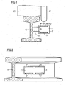
- FIG. 1 shows a schematic sectional view of a first embodiment of an attached to the rail wheel sensor according to the invention. Shown is in a section perpendicular to the rail longitudinal direction, a wheel sensor 1, which has a sensor coil 2 and a further coil 3. The sensor coil 2 and the further coil are arranged in a housing 4 of the wheel sensor 1, wherein the wheel sensor 1 or the housing 4 of the wheel sensor 1 is fastened by means of fastening means 5 to a rail 10.
- the sensor coil 2 is fed by an alternating current and is part of a sensitive to an inductive interaction of the sensor coil 2 with regardrollenden wheels resonant circuit.
- the sensor coil 2 is connected to suppress interference fields with the other coil 3 in a counter circuit.
- FIG. 1 was in FIG. 1 not only on the presentation of the aforementioned electrical components or compounds, but in addition to a reproduction of other known per se components of the wheel sensor 1. This applies, for example, optionally in the wheel sensor 1 existing monitoring or evaluation circuit and cable guides from and to the wheel sensor. 1
- FIG. 1 is the wheel sensor 1 in its position on the rail when crossing a wheel 20 having a flange 21 shown.
- the sensor coil 2 of the wheel sensor 1 is positioned on the rail 10 in such a way that the field of the sensor coil 2 is damped or damped by the wheel flange 21 of the wheel 20.
- the further coil 3 is arranged below the sensor coil 2 in relation to a wheel sensor 1 mounted or mounted on the rail.
- the distance A between the sensor coil 2 and the other coil 3 is at least one third of the inner diameter D of the sensor coil 2. This ensures that the influence of the other coil 3 with respect to a wheel detection is sufficiently low, so that otherwise due the countercurrent of the sensor coil 2 and the other coil 3 caused reduction of the sensitivity or the operability of the wheel sensor 1 with respect to wheels to be detected 20 or flanges 21 of wheels 20 is avoided.
- the further coil 3 essentially does not contribute to the wheel detection, but at least mainly serves the compensation of interference fields, in particular the rail current compensation.
- both the sensor coil 2 and the further coil 3 are air coils, which avoids problems due to Saturation effects on coils with iron cores can occur.
- Deviating from the presentation of FIG. 1 is also an embodiment conceivable in which the sensor coil 2 and the other coil 3 with respect to their nature, ie in particular their geometry and / or their number of turns differ from each other. This can advantageously be used to achieve optimal interference field compensation as a function of the respective rail profile.
- the background here is that, for example, the magnetic field caused by a rail current is generally not height-dependent due to the rail geometry, so that the voltage induced in the sensor coil 2 when using similar coils will usually deviate from the voltage induced in the further coil 3.
- FIG. 2 shows a perspective side view of a mounted on a rail second embodiment of a wheel sensor according to the invention with two sensor devices.
- those components that are with in FIG. 1 Components shown are identical or substantially functionally identical, denoted by the same reference numerals.
- the illustrated wheel sensor 1 has two sensor coils 2 and 6 and two further coils 3 and 7 which are accommodated in the housing 4 of the wheel sensor 1.
- the coils 2 and 3 and the coils 6 and 7 are part of a sensor device, ie the illustrated wheel sensor 1 has two sensor devices.
- the sensor coil 2 or 6 of the respective sensor device with the respective further coil 3 or 7 of the respective Sensor device connected in a counter circuit, so that interference fields are compensated.
- the wheel sensor 1 has two sensor devices, due to a temporal correlation of the signals detected by the sensor devices, it becomes possible to determine the direction of travel of a passing wheel or of a rail vehicle rolling past it. Due to this, the wheel sensor shown is particularly suitable for use in the context of train detection systems.
- the wheel sensor 1 is advantageous to the extent that externally induced disturbances are largely suppressed because they affect both the sensor coil 2 and 6 and the further coil 3 and 7 substantially equally.
- These include in particular rail currents, since the symmetry of the coupling is particularly high here.
- disturbances of other sources can be compensated advantageously.
- the superimposed arrangement of the coils of a sensor device advantageously makes it possible, in an embodiment with only one sensor device, for each of the coils, i. For example, both for the sensor coil 2 and for the further coil 3, the length of the housing 4 in the rail longitudinal direction can be fully utilized.
- the wheel sensor according to the invention advantageously also allows a particularly compact design, i. a particularly small housing length in the rail longitudinal direction to realize. This is particularly advantageous in situations where space is limited on the track.
Landscapes
- Engineering & Computer Science (AREA)
- Automation & Control Theory (AREA)
- Mechanical Engineering (AREA)
- Train Traffic Observation, Control, And Security (AREA)
- Measurement Of Length, Angles, Or The Like Using Electric Or Magnetic Means (AREA)
Applications Claiming Priority (2)
| Application Number | Priority Date | Filing Date | Title |
|---|---|---|---|
| DE102008056481A DE102008056481A1 (de) | 2008-11-05 | 2008-11-05 | Radsensor |
| PCT/EP2009/062913 WO2010052081A1 (de) | 2008-11-05 | 2009-10-05 | Radsensor |
Publications (2)
| Publication Number | Publication Date |
|---|---|
| EP2349810A1 EP2349810A1 (de) | 2011-08-03 |
| EP2349810B1 true EP2349810B1 (de) | 2014-08-13 |
Family
ID=41396051
Family Applications (1)
| Application Number | Title | Priority Date | Filing Date |
|---|---|---|---|
| EP09736400.4A Active EP2349810B1 (de) | 2008-11-05 | 2009-10-05 | Radsensor |
Country Status (5)
| Country | Link |
|---|---|
| US (1) | US8590845B2 (zh) |
| EP (1) | EP2349810B1 (zh) |
| CN (1) | CN102202953B (zh) |
| DE (1) | DE102008056481A1 (zh) |
| WO (1) | WO2010052081A1 (zh) |
Families Citing this family (10)
| Publication number | Priority date | Publication date | Assignee | Title |
|---|---|---|---|---|
| DE102009053257B4 (de) * | 2009-11-05 | 2013-10-02 | Siemens Aktiengesellschaft | Radsensor |
| DE102009053801B4 (de) * | 2009-11-18 | 2019-03-21 | Knorr-Bremse Systeme für Schienenfahrzeuge GmbH | Verfahren und Einrichtung zur Zustandsüberwachung wenigstens einen Radsatz aufweisenden Drehgestells eines Schienenfahrzeugs |
| CN103448752B (zh) * | 2013-09-18 | 2015-10-28 | 周口市凯旺电子科技有限公司 | 一种车轮传感器 |
| CN107016171B (zh) * | 2017-03-14 | 2020-08-18 | 哈尔滨工业大学 | 一种单侧计轴传感器感应线圈空间配置的优化方法 |
| DE102018111448A1 (de) * | 2018-05-14 | 2019-11-14 | PINTSCH TIEFENBACH GmbH | Sensor zum Erfassen von Metallteilen, sowie Verfahren zum Abschwächen eines magnetischen Feldes |
| DE102018111454A1 (de) * | 2018-05-14 | 2019-11-14 | PINTSCH TIEFENBACH GmbH | Sensor zum Erfassen von Metallteilen, sowie Verfahren zum Abschwächen eines magnetischen Feldes |
| ES2862195T3 (es) * | 2018-09-06 | 2021-10-07 | Frauscher Sensortechnik GmbH | Disposición de sensor |
| DE102019125883A1 (de) * | 2019-09-26 | 2021-04-01 | Schaeffler Technologies AG & Co. KG | Linearaktuator mit Messvorrichtung zur Bestimmung einer Position eines linear bewegbaren Bauteils |
| DE102021212809A1 (de) | 2021-11-15 | 2023-05-17 | Siemens Mobility GmbH | Sensoreinrichtung und Verfahren zum Erfassen einer Magnetfeldänderung |
| CN114670893B (zh) * | 2022-04-26 | 2024-04-30 | 南京拓控信息科技股份有限公司 | 一种车轮掉块的检测方法 |
Family Cites Families (7)
| Publication number | Priority date | Publication date | Assignee | Title |
|---|---|---|---|---|
| US4283031A (en) * | 1977-12-14 | 1981-08-11 | Finch Colin M | System controlling apparatus which compares signals from sensors monitoring passing objects with pre-determined parameter information to control the system |
| DE69809781D1 (de) * | 1997-09-04 | 2003-01-09 | Foster Co L B | Eisenbahnraddetektor |
| AT406139B (de) * | 1998-04-08 | 2000-02-25 | Frauscher Josef | Radsensor |
| DE10137519A1 (de) | 2001-07-30 | 2003-02-13 | Siemens Ag | Radsensor |
| DE10221577B3 (de) * | 2002-05-08 | 2004-03-18 | Siemens Ag | Magnetischer Radsensor |
| CN2661525Y (zh) * | 2003-11-20 | 2004-12-08 | 徐大年 | 抗干扰车轮传感器 |
| CN201028974Y (zh) * | 2007-02-06 | 2008-02-27 | 河南辉煌科技股份有限公司 | 车轮传感器 |
-
2008
- 2008-11-05 DE DE102008056481A patent/DE102008056481A1/de not_active Withdrawn
-
2009
- 2009-10-05 CN CN200980144035.XA patent/CN102202953B/zh active Active
- 2009-10-05 WO PCT/EP2009/062913 patent/WO2010052081A1/de active Application Filing
- 2009-10-05 US US13/127,844 patent/US8590845B2/en active Active
- 2009-10-05 EP EP09736400.4A patent/EP2349810B1/de active Active
Also Published As
| Publication number | Publication date |
|---|---|
| WO2010052081A1 (de) | 2010-05-14 |
| CN102202953B (zh) | 2015-06-17 |
| US20110210213A1 (en) | 2011-09-01 |
| DE102008056481A1 (de) | 2010-05-06 |
| EP2349810A1 (de) | 2011-08-03 |
| US8590845B2 (en) | 2013-11-26 |
| CN102202953A (zh) | 2011-09-28 |
Similar Documents
| Publication | Publication Date | Title |
|---|---|---|
| EP2349810B1 (de) | Radsensor | |
| EP2496459B1 (de) | Radsensor | |
| EP3107791B1 (de) | Sensoreinrichtung zum erfassen einer magnetfeldänderung sowie anlage des spurgebundenen verkehrs mit zumindest einer solchen sensoreinrichtung | |
| WO2012004251A1 (de) | Induktive sensoreinrichtung sowie induktiver näherungssensor mit einer induktiven sensoreinrichtung | |
| DE102012212939A1 (de) | Radsensor | |
| WO2004103792A1 (de) | Schienenanordnung, weiche und transportvorrichtung mit magnetostriktiven sensoren | |
| EP2146886B1 (de) | Radsensor | |
| AT406139B (de) | Radsensor | |
| DE3334548A1 (de) | Verfahren und vorrichtung zur spurfuehrung eines gleislosen fahrzeuges | |
| DE202016000534U1 (de) | Vorrichtung zur Drehzahlerfassung | |
| EP1288098B1 (de) | Radsensor und Anordnung | |
| EP2797802B1 (de) | Sensoreinrichtung zum detektieren eines sich entlang einer fahrschiene bewegenden rades | |
| DE102007023476B4 (de) | Radsensor | |
| EP2382120B1 (de) | Radsensor | |
| EP3294608B1 (de) | Sensoreinrichtung zum detektieren eines sich entlang einer fahrschiene bewegenden rades | |
| DE102013219826A1 (de) | Lineare magnetische Schienenbremse | |
| DE9420736U1 (de) | Einrichtung zum Vermeiden von Fehlzählungen bei der Achszählung im Eisenbahnwesen | |
| EP3569466B1 (de) | Sensor zum erfassen von metallteilen, sowie verfahren zum abschwächen eines magnetischen feldes | |
| DE102019132963B4 (de) | Strommessanordnung | |
| DE2201769C3 (de) | Fahrzeugbetätigter Gleiskontakt zum Erzeugen von Anwesenheits- und/oder Richtungskriterien | |
| EP1440861A1 (de) | Sensor für Schienenfahrzeugräder |
Legal Events
| Date | Code | Title | Description |
|---|---|---|---|
| PUAI | Public reference made under article 153(3) epc to a published international application that has entered the european phase |
Free format text: ORIGINAL CODE: 0009012 |
|
| 17P | Request for examination filed |
Effective date: 20110428 |
|
| AK | Designated contracting states |
Kind code of ref document: A1 Designated state(s): AT BE BG CH CY CZ DE DK EE ES FI FR GB GR HR HU IE IS IT LI LT LU LV MC MK MT NL NO PL PT RO SE SI SK SM TR |
|
| DAX | Request for extension of the european patent (deleted) | ||
| 17Q | First examination report despatched |
Effective date: 20120716 |
|
| RAP1 | Party data changed (applicant data changed or rights of an application transferred) |
Owner name: SIEMENS AKTIENGESELLSCHAFT |
|
| GRAP | Despatch of communication of intention to grant a patent |
Free format text: ORIGINAL CODE: EPIDOSNIGR1 |
|
| INTG | Intention to grant announced |
Effective date: 20140310 |
|
| GRAS | Grant fee paid |
Free format text: ORIGINAL CODE: EPIDOSNIGR3 |
|
| GRAA | (expected) grant |
Free format text: ORIGINAL CODE: 0009210 |
|
| AK | Designated contracting states |
Kind code of ref document: B1 Designated state(s): AT BE BG CH CY CZ DE DK EE ES FI FR GB GR HR HU IE IS IT LI LT LU LV MC MK MT NL NO PL PT RO SE SI SK SM TR |
|
| REG | Reference to a national code |
Ref country code: GB Ref legal event code: FG4D Free format text: NOT ENGLISH |
|
| REG | Reference to a national code |
Ref country code: CH Ref legal event code: EP Ref country code: AT Ref legal event code: REF Ref document number: 682022 Country of ref document: AT Kind code of ref document: T Effective date: 20140815 |
|
| REG | Reference to a national code |
Ref country code: IE Ref legal event code: FG4D Free format text: LANGUAGE OF EP DOCUMENT: GERMAN |
|
| REG | Reference to a national code |
Ref country code: DE Ref legal event code: R096 Ref document number: 502009009794 Country of ref document: DE Effective date: 20140925 |
|
| REG | Reference to a national code |
Ref country code: NL Ref legal event code: VDEP Effective date: 20140813 |
|
| REG | Reference to a national code |
Ref country code: LT Ref legal event code: MG4D |
|
| PG25 | Lapsed in a contracting state [announced via postgrant information from national office to epo] |
Ref country code: SE Free format text: LAPSE BECAUSE OF FAILURE TO SUBMIT A TRANSLATION OF THE DESCRIPTION OR TO PAY THE FEE WITHIN THE PRESCRIBED TIME-LIMIT Effective date: 20140813 Ref country code: NO Free format text: LAPSE BECAUSE OF FAILURE TO SUBMIT A TRANSLATION OF THE DESCRIPTION OR TO PAY THE FEE WITHIN THE PRESCRIBED TIME-LIMIT Effective date: 20141113 Ref country code: PT Free format text: LAPSE BECAUSE OF FAILURE TO SUBMIT A TRANSLATION OF THE DESCRIPTION OR TO PAY THE FEE WITHIN THE PRESCRIBED TIME-LIMIT Effective date: 20141215 Ref country code: GR Free format text: LAPSE BECAUSE OF FAILURE TO SUBMIT A TRANSLATION OF THE DESCRIPTION OR TO PAY THE FEE WITHIN THE PRESCRIBED TIME-LIMIT Effective date: 20141114 Ref country code: BG Free format text: LAPSE BECAUSE OF FAILURE TO SUBMIT A TRANSLATION OF THE DESCRIPTION OR TO PAY THE FEE WITHIN THE PRESCRIBED TIME-LIMIT Effective date: 20141113 Ref country code: LT Free format text: LAPSE BECAUSE OF FAILURE TO SUBMIT A TRANSLATION OF THE DESCRIPTION OR TO PAY THE FEE WITHIN THE PRESCRIBED TIME-LIMIT Effective date: 20140813 Ref country code: ES Free format text: LAPSE BECAUSE OF FAILURE TO SUBMIT A TRANSLATION OF THE DESCRIPTION OR TO PAY THE FEE WITHIN THE PRESCRIBED TIME-LIMIT Effective date: 20140813 Ref country code: FI Free format text: LAPSE BECAUSE OF FAILURE TO SUBMIT A TRANSLATION OF THE DESCRIPTION OR TO PAY THE FEE WITHIN THE PRESCRIBED TIME-LIMIT Effective date: 20140813 |
|
| PG25 | Lapsed in a contracting state [announced via postgrant information from national office to epo] |
Ref country code: CY Free format text: LAPSE BECAUSE OF FAILURE TO SUBMIT A TRANSLATION OF THE DESCRIPTION OR TO PAY THE FEE WITHIN THE PRESCRIBED TIME-LIMIT Effective date: 20140813 Ref country code: IS Free format text: LAPSE BECAUSE OF FAILURE TO SUBMIT A TRANSLATION OF THE DESCRIPTION OR TO PAY THE FEE WITHIN THE PRESCRIBED TIME-LIMIT Effective date: 20141213 Ref country code: HR Free format text: LAPSE BECAUSE OF FAILURE TO SUBMIT A TRANSLATION OF THE DESCRIPTION OR TO PAY THE FEE WITHIN THE PRESCRIBED TIME-LIMIT Effective date: 20140813 Ref country code: LV Free format text: LAPSE BECAUSE OF FAILURE TO SUBMIT A TRANSLATION OF THE DESCRIPTION OR TO PAY THE FEE WITHIN THE PRESCRIBED TIME-LIMIT Effective date: 20140813 |
|
| PG25 | Lapsed in a contracting state [announced via postgrant information from national office to epo] |
Ref country code: NL Free format text: LAPSE BECAUSE OF FAILURE TO SUBMIT A TRANSLATION OF THE DESCRIPTION OR TO PAY THE FEE WITHIN THE PRESCRIBED TIME-LIMIT Effective date: 20140813 |
|
| PG25 | Lapsed in a contracting state [announced via postgrant information from national office to epo] |
Ref country code: RO Free format text: LAPSE BECAUSE OF FAILURE TO SUBMIT A TRANSLATION OF THE DESCRIPTION OR TO PAY THE FEE WITHIN THE PRESCRIBED TIME-LIMIT Effective date: 20140813 Ref country code: SK Free format text: LAPSE BECAUSE OF FAILURE TO SUBMIT A TRANSLATION OF THE DESCRIPTION OR TO PAY THE FEE WITHIN THE PRESCRIBED TIME-LIMIT Effective date: 20140813 Ref country code: EE Free format text: LAPSE BECAUSE OF FAILURE TO SUBMIT A TRANSLATION OF THE DESCRIPTION OR TO PAY THE FEE WITHIN THE PRESCRIBED TIME-LIMIT Effective date: 20140813 Ref country code: DK Free format text: LAPSE BECAUSE OF FAILURE TO SUBMIT A TRANSLATION OF THE DESCRIPTION OR TO PAY THE FEE WITHIN THE PRESCRIBED TIME-LIMIT Effective date: 20140813 |
|
| REG | Reference to a national code |
Ref country code: DE Ref legal event code: R097 Ref document number: 502009009794 Country of ref document: DE |
|
| PG25 | Lapsed in a contracting state [announced via postgrant information from national office to epo] |
Ref country code: PL Free format text: LAPSE BECAUSE OF FAILURE TO SUBMIT A TRANSLATION OF THE DESCRIPTION OR TO PAY THE FEE WITHIN THE PRESCRIBED TIME-LIMIT Effective date: 20140813 Ref country code: LU Free format text: LAPSE BECAUSE OF FAILURE TO SUBMIT A TRANSLATION OF THE DESCRIPTION OR TO PAY THE FEE WITHIN THE PRESCRIBED TIME-LIMIT Effective date: 20141005 Ref country code: MC Free format text: LAPSE BECAUSE OF FAILURE TO SUBMIT A TRANSLATION OF THE DESCRIPTION OR TO PAY THE FEE WITHIN THE PRESCRIBED TIME-LIMIT Effective date: 20140813 |
|
| REG | Reference to a national code |
Ref country code: CH Ref legal event code: PL |
|
| PLBE | No opposition filed within time limit |
Free format text: ORIGINAL CODE: 0009261 |
|
| STAA | Information on the status of an ep patent application or granted ep patent |
Free format text: STATUS: NO OPPOSITION FILED WITHIN TIME LIMIT |
|
| PG25 | Lapsed in a contracting state [announced via postgrant information from national office to epo] |
Ref country code: BE Free format text: LAPSE BECAUSE OF NON-PAYMENT OF DUE FEES Effective date: 20141031 |
|
| 26N | No opposition filed |
Effective date: 20150515 |
|
| GBPC | Gb: european patent ceased through non-payment of renewal fee |
Effective date: 20141113 |
|
| REG | Reference to a national code |
Ref country code: IE Ref legal event code: MM4A |
|
| PG25 | Lapsed in a contracting state [announced via postgrant information from national office to epo] |
Ref country code: LI Free format text: LAPSE BECAUSE OF NON-PAYMENT OF DUE FEES Effective date: 20141031 Ref country code: CH Free format text: LAPSE BECAUSE OF NON-PAYMENT OF DUE FEES Effective date: 20141031 |
|
| REG | Reference to a national code |
Ref country code: FR Ref legal event code: PLFP Year of fee payment: 7 |
|
| PG25 | Lapsed in a contracting state [announced via postgrant information from national office to epo] |
Ref country code: GB Free format text: LAPSE BECAUSE OF NON-PAYMENT OF DUE FEES Effective date: 20141113 Ref country code: IE Free format text: LAPSE BECAUSE OF NON-PAYMENT OF DUE FEES Effective date: 20141005 |
|
| PG25 | Lapsed in a contracting state [announced via postgrant information from national office to epo] |
Ref country code: SI Free format text: LAPSE BECAUSE OF FAILURE TO SUBMIT A TRANSLATION OF THE DESCRIPTION OR TO PAY THE FEE WITHIN THE PRESCRIBED TIME-LIMIT Effective date: 20140813 |
|
| PG25 | Lapsed in a contracting state [announced via postgrant information from national office to epo] |
Ref country code: SM Free format text: LAPSE BECAUSE OF FAILURE TO SUBMIT A TRANSLATION OF THE DESCRIPTION OR TO PAY THE FEE WITHIN THE PRESCRIBED TIME-LIMIT Effective date: 20140813 |
|
| PG25 | Lapsed in a contracting state [announced via postgrant information from national office to epo] |
Ref country code: TR Free format text: LAPSE BECAUSE OF FAILURE TO SUBMIT A TRANSLATION OF THE DESCRIPTION OR TO PAY THE FEE WITHIN THE PRESCRIBED TIME-LIMIT Effective date: 20140813 Ref country code: MT Free format text: LAPSE BECAUSE OF FAILURE TO SUBMIT A TRANSLATION OF THE DESCRIPTION OR TO PAY THE FEE WITHIN THE PRESCRIBED TIME-LIMIT Effective date: 20140813 Ref country code: HU Free format text: LAPSE BECAUSE OF FAILURE TO SUBMIT A TRANSLATION OF THE DESCRIPTION OR TO PAY THE FEE WITHIN THE PRESCRIBED TIME-LIMIT; INVALID AB INITIO Effective date: 20091005 |
|
| REG | Reference to a national code |
Ref country code: FR Ref legal event code: PLFP Year of fee payment: 8 |
|
| REG | Reference to a national code |
Ref country code: FR Ref legal event code: PLFP Year of fee payment: 9 |
|
| PG25 | Lapsed in a contracting state [announced via postgrant information from national office to epo] |
Ref country code: MK Free format text: LAPSE BECAUSE OF FAILURE TO SUBMIT A TRANSLATION OF THE DESCRIPTION OR TO PAY THE FEE WITHIN THE PRESCRIBED TIME-LIMIT Effective date: 20140813 |
|
| REG | Reference to a national code |
Ref country code: FR Ref legal event code: PLFP Year of fee payment: 10 |
|
| REG | Reference to a national code |
Ref country code: DE Ref legal event code: R081 Ref document number: 502009009794 Country of ref document: DE Owner name: SIEMENS MOBILITY GMBH, DE Free format text: FORMER OWNER: SIEMENS AKTIENGESELLSCHAFT, 80333 MUENCHEN, DE |
|
| REG | Reference to a national code |
Ref country code: AT Ref legal event code: PC Ref document number: 682022 Country of ref document: AT Kind code of ref document: T Owner name: SIEMENS MOBILITY GMBH, DE Effective date: 20190506 |
|
| PGFP | Annual fee paid to national office [announced via postgrant information from national office to epo] |
Ref country code: IT Payment date: 20191029 Year of fee payment: 11 Ref country code: FR Payment date: 20191017 Year of fee payment: 11 |
|
| PG25 | Lapsed in a contracting state [announced via postgrant information from national office to epo] |
Ref country code: FR Free format text: LAPSE BECAUSE OF NON-PAYMENT OF DUE FEES Effective date: 20201031 |
|
| PG25 | Lapsed in a contracting state [announced via postgrant information from national office to epo] |
Ref country code: IT Free format text: LAPSE BECAUSE OF NON-PAYMENT OF DUE FEES Effective date: 20201005 |
|
| PGFP | Annual fee paid to national office [announced via postgrant information from national office to epo] |
Ref country code: CZ Payment date: 20211005 Year of fee payment: 13 |
|
| PG25 | Lapsed in a contracting state [announced via postgrant information from national office to epo] |
Ref country code: CZ Free format text: LAPSE BECAUSE OF NON-PAYMENT OF DUE FEES Effective date: 20221005 |
|
| PGFP | Annual fee paid to national office [announced via postgrant information from national office to epo] |
Ref country code: DE Payment date: 20231214 Year of fee payment: 15 Ref country code: AT Payment date: 20230911 Year of fee payment: 15 |