EP2348288B1 - Anordnung mit einem an einem Träger befestigten Maßstab - Google Patents
Anordnung mit einem an einem Träger befestigten Maßstab Download PDFInfo
- Publication number
- EP2348288B1 EP2348288B1 EP10174572.7A EP10174572A EP2348288B1 EP 2348288 B1 EP2348288 B1 EP 2348288B1 EP 10174572 A EP10174572 A EP 10174572A EP 2348288 B1 EP2348288 B1 EP 2348288B1
- Authority
- EP
- European Patent Office
- Prior art keywords
- scale
- balls
- carrier
- arrangement according
- holding means
- Prior art date
- Legal status (The legal status is an assumption and is not a legal conclusion. Google has not performed a legal analysis and makes no representation as to the accuracy of the status listed.)
- Active
Links
- 239000000463 material Substances 0.000 claims description 19
- 238000005259 measurement Methods 0.000 claims description 13
- 230000001070 adhesive effect Effects 0.000 description 12
- 239000000853 adhesive Substances 0.000 description 11
- 239000011521 glass Substances 0.000 description 4
- 230000001419 dependent effect Effects 0.000 description 3
- 229920002120 photoresistant polymer Polymers 0.000 description 3
- 239000006094 Zerodur Substances 0.000 description 2
- 230000002411 adverse Effects 0.000 description 2
- 230000032683 aging Effects 0.000 description 2
- 229910000679 solder Inorganic materials 0.000 description 2
- 229910001374 Invar Inorganic materials 0.000 description 1
- 238000004026 adhesive bonding Methods 0.000 description 1
- 239000011248 coating agent Substances 0.000 description 1
- 238000000576 coating method Methods 0.000 description 1
- 230000000694 effects Effects 0.000 description 1
- 239000002241 glass-ceramic Substances 0.000 description 1
- 229910052751 metal Inorganic materials 0.000 description 1
- 239000002184 metal Substances 0.000 description 1
- 150000002739 metals Chemical class 0.000 description 1
- 239000000203 mixture Substances 0.000 description 1
- 229920000642 polymer Polymers 0.000 description 1
- 238000005476 soldering Methods 0.000 description 1
- 239000007787 solid Substances 0.000 description 1
- 230000035882 stress Effects 0.000 description 1
- 238000003466 welding Methods 0.000 description 1
Images

Classifications
-
- G—PHYSICS
- G01—MEASURING; TESTING
- G01D—MEASURING NOT SPECIALLY ADAPTED FOR A SPECIFIC VARIABLE; ARRANGEMENTS FOR MEASURING TWO OR MORE VARIABLES NOT COVERED IN A SINGLE OTHER SUBCLASS; TARIFF METERING APPARATUS; MEASURING OR TESTING NOT OTHERWISE PROVIDED FOR
- G01D5/00—Mechanical means for transferring the output of a sensing member; Means for converting the output of a sensing member to another variable where the form or nature of the sensing member does not constrain the means for converting; Transducers not specially adapted for a specific variable
- G01D5/26—Mechanical means for transferring the output of a sensing member; Means for converting the output of a sensing member to another variable where the form or nature of the sensing member does not constrain the means for converting; Transducers not specially adapted for a specific variable characterised by optical transfer means, i.e. using infrared, visible, or ultraviolet light
- G01D5/32—Mechanical means for transferring the output of a sensing member; Means for converting the output of a sensing member to another variable where the form or nature of the sensing member does not constrain the means for converting; Transducers not specially adapted for a specific variable characterised by optical transfer means, i.e. using infrared, visible, or ultraviolet light with attenuation or whole or partial obturation of beams of light
- G01D5/34—Mechanical means for transferring the output of a sensing member; Means for converting the output of a sensing member to another variable where the form or nature of the sensing member does not constrain the means for converting; Transducers not specially adapted for a specific variable characterised by optical transfer means, i.e. using infrared, visible, or ultraviolet light with attenuation or whole or partial obturation of beams of light the beams of light being detected by photocells
- G01D5/347—Mechanical means for transferring the output of a sensing member; Means for converting the output of a sensing member to another variable where the form or nature of the sensing member does not constrain the means for converting; Transducers not specially adapted for a specific variable characterised by optical transfer means, i.e. using infrared, visible, or ultraviolet light with attenuation or whole or partial obturation of beams of light the beams of light being detected by photocells using displacement encoding scales
- G01D5/34707—Scales; Discs, e.g. fixation, fabrication, compensation
Definitions
- a scale is to be attached to one of the machine parts, and a scanning unit is attached to the other of the mutually movable machine parts.
- a measurement graduation of the scale is scanned by the scanning unit and position-dependent scanning signals are generated.
- a scale is mounted on a support by supporting itself on balls.
- the balls are mounted in a rollable manner in small areas.
- the holding force between the scale and the carrier is initiated by springs.
- the ball and spring combination allows attachment and support only at the edge of the scale, eliminating the need for leveling within the actual range of the scale.
- the object of the invention is to provide an arrangement with a scale attached to a support, wherein the scale is kept stable and drift-free on the support. Furthermore, the attachment should be possible as simple and inexpensive means possible.
- the scale has a measuring graduation and is supported by two-dimensionally distributed balls arranged on the carrier.
- the measurement graduation defines a measurement area on a surface of the scale, and the surface of the scale opposite the measurement graduation forms a support surface which contacts the spheres.
- the holding force between the carrier and the scale is applied by the balls are fixed on the one hand on the carrier and on the other hand on the scale immovable.
- a holding means for this immovable stationary attachment of the balls is a holding means, in particular an adhesive which causes a cohesive attachment of the balls.
- This holding means is preferably designed as a coating, wherein there are several possibilities for this purpose.
- the layer in which the balls are fixedly attached to the carrier can be applied to the carrier and / or the layer is applied in the form of an envelope on the balls.
- the layer in which the balls are fixedly attached to the scale may be applied to the scale and / or the layer is applied in the form of an envelope on the balls. In the assembled state, these layers are penetrated by the balls, so that a direct contact of the balls with the bearing surface of the scale and the carrier is present, without the interposition of layer material.
- an adhesive in particular adhesive, which shrinks during curing and this shrinkage effect is positively used, thereby generating a holding force acting as a tension spring, whereby the support surface of the scale is drawn to the balls.
- the balls are arranged at a mutual center distance which is smaller than the thickness of the scale.
- the balls and the means for attachment, so the holding means are arranged and formed such that form between them free spaces, which form outwardly leading channels. These channels extending in the space between the scale and the carrier correspond to the surrounding medium.
- the materials of support and scale each have the same coefficient of thermal expansion.
- the coefficient of expansion of the carrier and the scale is preferably less than 0.1 ⁇ 10 -6 K -1 .
- the balls are made of a material that withstands occurring compressive forces as possible without deformation.
- a suitable material is for example glass.
- planar flatness - even of a large scale - is maintained in the arrangement according to the invention or is not disturbed, since disturbing media can be deposited in the spaces formed by the free spaces.
- the scale is stably fixed to the carrier during measurement operation, which means high rigidity in the measuring direction and perpendicular to the graduation plane.
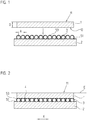
- a scale 1 made of glass or glass ceramic (eg ZERODUR) with a measuring graduation 11 is shown.
- the measuring graduation 11 is an incremental graduation, which is scanned photoelectrically during the position measurement in two measuring directions X and Y by a scanning unit, not shown, for generating position-dependent scanning signals.
- the measuring graduation 11 may be a reflective amplitude grating or a phase grating, which serves in a known manner for high-precision interferential position measurement.
- the scale 1 is held on a support 2 during this position measurement. This support 2 is preferably made of a material having the same coefficient of expansion as the scale 1.
- the mean thermal expansion coefficient ⁇ in the temperature range of 0 ° to 50 ° of scale 1 and support 2 is preferably less than 0.1 x 10 -6 K -1 when using so-called zero-expansion glasses such as ZERODUR, SITAL and ULE, and smaller than 1.5 x 10 -6 K -1 when using metals such as INVAR.
- balls 3 are spatially distributed two-dimensionally, either distributed geometrically evenly in a regular grid or distributed statistically.
- the balls 3 are arranged with a mutual center distance A of smaller than the thickness D of the scale 1.
- the balls 3 are arranged at a mutual center distance A smaller 1/10 of the thickness D of the scale 1. This condition is fulfilled at each point of the two-dimensional distribution of the balls 3, but at least within the measuring range M.
- the measuring range M is defined by the range of the measuring graduation 11, which is used for high-precision position measurement.
- the thickness D of the scale 1 is the distance between the measuring graduation plane E, in which the measuring graduation 11 is located, and the support surface 12, with which it is supported on the balls 3.
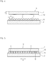
- FIG. 3 the two-dimensional measuring graduation 11 of the scale 1 is shown in plan view.
- the scale 1 is omitted in the upper left part of the view.
- FIG. 3 shown as a plan view two-dimensional spatial distribution of the balls 3 takes place in such a way that between the balls 3 free spaces 4 arise, which communicate with each other and thus form outwardly leading channels.
- the air over the entire surface of the scale 1 through the channels can be discharged homogeneously outward into the environment, which ensures a good flatness of the scale 1.
- Typical values for the thickness D of scale 1 are 0.5mm to 15mm.
- the balls 3 are made of a material that withstands occurring compressive forces as possible without deformation.
- a suitable material is for example glass.
- the balls 3 are made of a material having the same coefficient of expansion as the scale 1.
- the balls 3 have in particular a diameter between 20 .mu.m and 200 .mu.m, typically 50 microns.
- the tolerance of the balls with respect to diameter and roundness is preferably less than 5 microns, d. h., At a nominal diameter of 50 microns, the balls 3 have a maximum deviation of ⁇ 5 microns.
- the actual attachment of the scale 1 on the support 2 is carried out in all embodiments by immovable attachment of the balls 3 on the one hand to the support 2 and on the other hand on the scale 1.
- These fasteners are cohesive connections, so for example gluing, soldering or welding.
- drift-free mounting of the balls 3 on the scale 1 and on the carrier 2 is a holding means in the form of a layer 51 applied to the carrier 2, in which the balls 3 are embedded and thereby locally stable bound to the carrier 2.
- This layer 51 is an adhesive, such as a hard-setting adhesive, a photoresist or a polymer, and has a thickness that is a fraction of the diameter of the balls 3.
- the fixation of the scale 1 relative to the now fixed to the carrier 2 balls 3 is also carried out with a holding means 53 in the form of an adhesive, for example in the form of an adhesive or other solid curing material, which surrounds the balls 3 and has an adhesive effect.
- the balls 3 contact on the one hand the scale 1 on its underside, so the support surface 12 each punctiform and on the other hand, the carrier 2 also punctiform. This ensures that the flatness of the scale 1 is not adversely affected by other media, such as the adhesive.
- the holding means 51, 53 have the purpose only to fix the balls 3 stationary and to generate and maintain the holding force between the carrier 2 and the scale 1.
- the holding means 51, 53 that is to say the layer material, has sufficient volume for the curing and also the subsequent aging, without influencing the distance between the carrier 2 and the scale 1.
- these free spaces 4 communicate with each other and thus form channels leading to the outside.
- the air over the entire surface of the scale 1 through the channels can be discharged homogeneously outward into the environment, which ensures a good flatness of the scale 1 during assembly and also during the measuring operation.
- interconnected open spaces 4 have the advantage that when placing the scale 1 on the balls 3 air in the space can escape forcibly forces. Furthermore, it is possible to use the free spaces 4 as channels for vacuum suction of the scale 1. In this case, the scale 1 is placed on the balls 3 and a holding force introduced by forming negative pressure in the free spaces 3 until the layer material is completely cured.
- the leading to the outside spaces 4 can also be used to rinse the space between the balls 3 with a medium, for example, to influence the layer material specifically or for temperature control. Instead of negative pressure, overpressure can also be applied or a medium which dissolves the layer material can be introduced in order to enable disassembly of the scale 1.
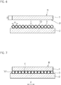
- FIGS. 4 and 5 illustrated second embodiment differs from the first embodiment only in that for stationary positional fixation of the balls 3 on scale 1, a holding means in the form of a layer 52 is applied to the support surface 12 of the scale 1.
- the balls 3 on the one hand touch the scale 1 punctiformly on its supporting surface 12, thus puncturing the layer 52 when the scale 1 is applied.
- the balls 3 also contact the carrier 2 in a punctiform manner. This ensures that the flatness of the scale 1 is not adversely affected by other media, in particular the layer material.
- the holding means 51, 52 have only the purpose to fix the balls 3 stationary and to generate and maintain the holding force between the carrier 2 and the scale 1.
- the spherical shape and the suitable choice of the thickness of the layers 51 and 52 ensures that between each two balls 3, even if they abut each other, free spaces 4 arise.
- the holding means 51, 52 that is to say the layer material, has sufficient volume for the curing and also the subsequent aging, without influencing the distance between the carrier 2 and the scale 1.
- these free spaces 4 communicate with each other and thus form channels leading to the outside.
- the air over the entire surface of the scale 1 through the channels can be discharged homogeneously outward into the environment, which ensures a good flatness of the scale 1 during assembly and also during the measuring operation.
- FIGS. 6 and 7 illustrated third embodiment with respect to the first embodiment acts as a holding means only acting as a sheathing of the balls 3 layer 53 for stationary fixation of the balls 3 on the carrier 2 and for stationary fixation of the balls on scale 1.
- This serving can be realized by the balls 3 are mixed in a holding means, such as adhesive or photoresist, so that the balls 3 are distributed therein and this mixture is applied to the carrier 2.
- these can also be fixed in a carrier, for example in a film, with this prefabricated film then being placed on the carrier 2 and / or the scale 1.
- the stationary support between the balls 3 and the carrier 2 and the balls 3 and the scale 1 by adhesive in the form of adhesives, photoresist, solder material (eg glass solder), sintered layers or by cold bonding will be realized.
- an absolute coding can also be provided.
Landscapes
- Physics & Mathematics (AREA)
- General Physics & Mathematics (AREA)
- Optical Transform (AREA)
- A Measuring Device Byusing Mechanical Method (AREA)
- Length Measuring Devices With Unspecified Measuring Means (AREA)
- Transmission And Conversion Of Sensor Element Output (AREA)
- Length-Measuring Instruments Using Mechanical Means (AREA)
Applications Claiming Priority (1)
| Application Number | Priority Date | Filing Date | Title |
|---|---|---|---|
| DE102009047120A DE102009047120A1 (de) | 2009-11-25 | 2009-11-25 | Anordnung mit einem an einem Träger befestigten Maßstab |
Publications (3)
| Publication Number | Publication Date |
|---|---|
| EP2348288A2 EP2348288A2 (de) | 2011-07-27 |
| EP2348288A3 EP2348288A3 (de) | 2016-06-15 |
| EP2348288B1 true EP2348288B1 (de) | 2016-12-28 |
Family
ID=43901884
Family Applications (1)
| Application Number | Title | Priority Date | Filing Date |
|---|---|---|---|
| EP10174572.7A Active EP2348288B1 (de) | 2009-11-25 | 2010-08-31 | Anordnung mit einem an einem Träger befestigten Maßstab |
Country Status (6)
| Country | Link |
|---|---|
| US (1) | US8234793B2 (ja) |
| EP (1) | EP2348288B1 (ja) |
| JP (1) | JP5579024B2 (ja) |
| CN (1) | CN102095372B (ja) |
| DE (1) | DE102009047120A1 (ja) |
| ES (1) | ES2613038T3 (ja) |
Families Citing this family (8)
| Publication number | Priority date | Publication date | Assignee | Title |
|---|---|---|---|---|
| DE102009002142A1 (de) * | 2009-04-02 | 2010-10-07 | Dr. Johannes Heidenhain Gmbh | Anordnung mit einem an einem Träger befestigten Maßstab und Verfahren zum Halten eines Maßstabs an einem Träger |
| DE102009045515B3 (de) * | 2009-10-09 | 2011-03-03 | Dreier Lasermesstechnik Gmbh | Vorrichtung zur Überprüfung der Genauigkeit von Werkzeugmaschinen und Messeinrichtungen |
| KR101648200B1 (ko) | 2009-10-22 | 2016-08-12 | 삼성전자주식회사 | 이미지 센서 및 그 제조 방법 |
| DE102009047120A1 (de) * | 2009-11-25 | 2011-05-26 | Dr. Johannes Heidenhain Gmbh | Anordnung mit einem an einem Träger befestigten Maßstab |
| DE102013220190B4 (de) * | 2013-10-07 | 2021-08-12 | Dr. Johannes Heidenhain Gmbh | Messteilung und lichtelektrische Positionsmesseinrichtung mit dieser Messteilung |
| US9612107B2 (en) * | 2014-06-10 | 2017-04-04 | Faro Technologies, Inc. | Length artifact and method of measurement |
| ES2615116T3 (es) * | 2014-11-19 | 2017-06-05 | Dr. Johannes Heidenhain Gmbh | Disposición con una escala de medición fijada en un soporte |
| IT201900003817A1 (it) * | 2019-03-15 | 2020-09-15 | Parpas S P A | Encoder lineare |
Family Cites Families (17)
| Publication number | Priority date | Publication date | Assignee | Title |
|---|---|---|---|---|
| DE3635511A1 (de) * | 1986-10-18 | 1988-04-28 | Zeiss Carl Fa | Halterung fuer mass- und formverkoerperung |
| JP2683148B2 (ja) * | 1990-09-04 | 1997-11-26 | アルプス電気株式会社 | 透明タツチスイツチ |
| JPH06324221A (ja) * | 1993-05-11 | 1994-11-25 | Nippon Telegr & Teleph Corp <Ntt> | 光ファイバアレイ |
| DE4406799C2 (de) * | 1994-03-02 | 1997-11-06 | Heidenhain Gmbh Dr Johannes | Positionsmeßeinrichtung |
| US5778553A (en) * | 1996-07-03 | 1998-07-14 | Hollensbe; Homer D. | Dimension transfer tool |
| JP4218916B2 (ja) * | 1999-07-27 | 2009-02-04 | フジノン株式会社 | 被測定体の支持装置の製造方法 |
| US6964113B2 (en) * | 2001-03-06 | 2005-11-15 | Faro Laser Trackers, Llc | Scale-bar artifact and methods of use |
| JP4477440B2 (ja) * | 2004-07-15 | 2010-06-09 | 株式会社ミツトヨ | スケール弾性保持方法及び位置測定装置 |
| EP1742023A1 (de) * | 2005-07-06 | 2007-01-10 | Schneeberger Holding AG | Linearführungssystem mit Vorrichtung zur Positionsmessung |
| US7707739B2 (en) * | 2005-11-04 | 2010-05-04 | Dr. Johannes Heidenhain Gmbh | Method for attaching a scale to a carrier, a scale, and carrier having a scale |
| EP1783463B1 (de) * | 2005-11-04 | 2015-04-15 | Dr. Johannes Heidenhain GmbH | Verfahren zum Befestigen eines Massstabs an einen Träger, dazu ausgebildeter Massstab sowie Träger mit diesem Massstab |
| DE102005053088A1 (de) * | 2005-11-04 | 2007-05-10 | Dr. Johannes Heidenhain Gmbh | Verfahren zum Befestigen eines Maßstabs an einen Träger sowie Maßstab und Träger mit diesem Maßstab |
| EP2002216B1 (de) * | 2006-03-29 | 2015-07-08 | Dr. Johannes Heidenhain GmbH | Verfahren zum halten eines massstabs an einem träger sowie anordnung mit einem träger und einem massstab |
| US8007609B2 (en) * | 2007-10-31 | 2011-08-30 | Symphony Acoustics, Inc. | Parallel plate arrangement and method of formation |
| DE102009002142A1 (de) * | 2009-04-02 | 2010-10-07 | Dr. Johannes Heidenhain Gmbh | Anordnung mit einem an einem Träger befestigten Maßstab und Verfahren zum Halten eines Maßstabs an einem Träger |
| US8051575B2 (en) * | 2009-10-20 | 2011-11-08 | Faro Technologies, Inc. | Mounted scale bar |
| DE102009047120A1 (de) * | 2009-11-25 | 2011-05-26 | Dr. Johannes Heidenhain Gmbh | Anordnung mit einem an einem Träger befestigten Maßstab |
-
2009
- 2009-11-25 DE DE102009047120A patent/DE102009047120A1/de not_active Withdrawn
-
2010
- 2010-08-31 ES ES10174572.7T patent/ES2613038T3/es active Active
- 2010-08-31 EP EP10174572.7A patent/EP2348288B1/de active Active
- 2010-11-12 JP JP2010254042A patent/JP5579024B2/ja active Active
- 2010-11-16 US US12/927,488 patent/US8234793B2/en active Active
- 2010-11-25 CN CN201010562650.7A patent/CN102095372B/zh active Active
Non-Patent Citations (1)
| Title |
|---|
| None * |
Also Published As
| Publication number | Publication date |
|---|---|
| JP2011145281A (ja) | 2011-07-28 |
| CN102095372A (zh) | 2011-06-15 |
| CN102095372B (zh) | 2015-09-30 |
| EP2348288A3 (de) | 2016-06-15 |
| US8234793B2 (en) | 2012-08-07 |
| JP5579024B2 (ja) | 2014-08-27 |
| EP2348288A2 (de) | 2011-07-27 |
| US20110119945A1 (en) | 2011-05-26 |
| ES2613038T3 (es) | 2017-05-22 |
| DE102009047120A1 (de) | 2011-05-26 |
Similar Documents
| Publication | Publication Date | Title |
|---|---|---|
| EP2348288B1 (de) | Anordnung mit einem an einem Träger befestigten Maßstab | |
| EP3026389B1 (de) | Längenmesseinrichtung | |
| EP2002216B1 (de) | Verfahren zum halten eines massstabs an einem träger sowie anordnung mit einem träger und einem massstab | |
| EP2414783B1 (de) | Anordnung mit einem an einem träger befestigten massstab und verfahren zum halten eines massstabs an einem träger | |
| EP1307750A1 (de) | Mikromechanisches bauelement | |
| WO2000067310A1 (de) | Mikroelektronische baugruppe | |
| AT515951B1 (de) | Positioniereinheit | |
| EP1783463A1 (de) | Verfahren zum Befestigen eines Massstabs an einen Träger, dazu ausgebildeter Massstab sowie Träger mit diesem Massstab | |
| WO2017140313A1 (de) | Sensor und sensorelement | |
| EP1050070B1 (de) | Belichtungsanlage mit halteeinrichtung für ein substrat | |
| DE102008033592B4 (de) | Mikromechanischer Drucksensor | |
| EP3477263B1 (de) | Anordnung mit einem an einem träger befestigten massstab | |
| DE102012104552B4 (de) | Vorrichtung zum dynamischen Anregen eines Bauteils sowie Prüfstand mit selbiger | |
| EP3023742B1 (de) | Anordnung mit einer an einem Träger befestigten Maßverkörperung | |
| EP1731877B1 (de) | Geberelement eines Messsystems | |
| EP0975940B1 (de) | Linearer Kraftsensor mit zwei Schichten und zwei Stempeln | |
| EP4145083B1 (de) | Optische empfangseinheit | |
| EP1852674A1 (de) | Messvorrichtung zur Bestimmung des relativen Versatzes zwischen zwei Bauteilen | |
| EP3078940B1 (de) | Längenmesseinrichtung | |
| DE102007002772A1 (de) | Verfahren zum Halten eines Maßstabs an einem Träger sowie Anordnung mit einem Träger und einem Maßstab | |
| EP3977059B1 (de) | Stützglied für eine präzisionsvorrichtung, stützgerüst für eine präzisionsvorrichtung, sowie präzisionsvorrichtung mit einem solchen stützglied oder stützgerüst | |
| EP3214479A1 (de) | Vorrichtung zur deformation eines optischen elements und optisches element mit der vorrichtung | |
| DE102017131263A1 (de) | Verfahren zur Herstellung einer Messeinrichtung | |
| DE102010025633B4 (de) | Vorrichtung zur Messung kleiner und großer Kräfte | |
| WO2022078578A1 (de) | Druckmesszelle und verfahren zur herstellung einer druckmesszelle |
Legal Events
| Date | Code | Title | Description |
|---|---|---|---|
| PUAI | Public reference made under article 153(3) epc to a published international application that has entered the european phase |
Free format text: ORIGINAL CODE: 0009012 |
|
| AK | Designated contracting states |
Kind code of ref document: A2 Designated state(s): AL AT BE BG CH CY CZ DE DK EE ES FI FR GB GR HR HU IE IS IT LI LT LU LV MC MK MT NL NO PL PT RO SE SI SK SM TR |
|
| AX | Request for extension of the european patent |
Extension state: BA ME RS |
|
| PUAL | Search report despatched |
Free format text: ORIGINAL CODE: 0009013 |
|
| AK | Designated contracting states |
Kind code of ref document: A3 Designated state(s): AL AT BE BG CH CY CZ DE DK EE ES FI FR GB GR HR HU IE IS IT LI LT LU LV MC MK MT NL NO PL PT RO SE SI SK SM TR |
|
| AX | Request for extension of the european patent |
Extension state: BA ME RS |
|
| RIC1 | Information provided on ipc code assigned before grant |
Ipc: G01D 5/347 20060101AFI20160509BHEP |
|
| 17P | Request for examination filed |
Effective date: 20160518 |
|
| RBV | Designated contracting states (corrected) |
Designated state(s): AL AT BE BG CH CY CZ DE DK EE ES FI FR GB GR HR HU IE IS IT LI LT LU LV MC MK MT NL NO PL PT RO SE SI SK SM TR |
|
| GRAP | Despatch of communication of intention to grant a patent |
Free format text: ORIGINAL CODE: EPIDOSNIGR1 |
|
| INTG | Intention to grant announced |
Effective date: 20160921 |
|
| RIN1 | Information on inventor provided before grant (corrected) |
Inventor name: SPECKBACHER, PETER Inventor name: WEIDMANN, JOSEF |
|
| GRAS | Grant fee paid |
Free format text: ORIGINAL CODE: EPIDOSNIGR3 |
|
| GRAA | (expected) grant |
Free format text: ORIGINAL CODE: 0009210 |
|
| AK | Designated contracting states |
Kind code of ref document: B1 Designated state(s): AL AT BE BG CH CY CZ DE DK EE ES FI FR GB GR HR HU IE IS IT LI LT LU LV MC MK MT NL NO PL PT RO SE SI SK SM TR |
|
| REG | Reference to a national code |
Ref country code: GB Ref legal event code: FG4D Free format text: NOT ENGLISH |
|
| REG | Reference to a national code |
Ref country code: CH Ref legal event code: EP Ref country code: CH Ref legal event code: NV Representative=s name: ICB INGENIEURS CONSEILS EN BREVETS SA, CH |
|
| REG | Reference to a national code |
Ref country code: AT Ref legal event code: REF Ref document number: 857699 Country of ref document: AT Kind code of ref document: T Effective date: 20170115 |
|
| REG | Reference to a national code |
Ref country code: IE Ref legal event code: FG4D Free format text: LANGUAGE OF EP DOCUMENT: GERMAN |
|
| REG | Reference to a national code |
Ref country code: DE Ref legal event code: R096 Ref document number: 502010012948 Country of ref document: DE |
|
| PG25 | Lapsed in a contracting state [announced via postgrant information from national office to epo] |
Ref country code: LV Free format text: LAPSE BECAUSE OF FAILURE TO SUBMIT A TRANSLATION OF THE DESCRIPTION OR TO PAY THE FEE WITHIN THE PRESCRIBED TIME-LIMIT Effective date: 20161228 |
|
| REG | Reference to a national code |
Ref country code: LT Ref legal event code: MG4D |
|
| PG25 | Lapsed in a contracting state [announced via postgrant information from national office to epo] |
Ref country code: LT Free format text: LAPSE BECAUSE OF FAILURE TO SUBMIT A TRANSLATION OF THE DESCRIPTION OR TO PAY THE FEE WITHIN THE PRESCRIBED TIME-LIMIT Effective date: 20161228 Ref country code: NO Free format text: LAPSE BECAUSE OF FAILURE TO SUBMIT A TRANSLATION OF THE DESCRIPTION OR TO PAY THE FEE WITHIN THE PRESCRIBED TIME-LIMIT Effective date: 20170328 Ref country code: GR Free format text: LAPSE BECAUSE OF FAILURE TO SUBMIT A TRANSLATION OF THE DESCRIPTION OR TO PAY THE FEE WITHIN THE PRESCRIBED TIME-LIMIT Effective date: 20170329 Ref country code: SE Free format text: LAPSE BECAUSE OF FAILURE TO SUBMIT A TRANSLATION OF THE DESCRIPTION OR TO PAY THE FEE WITHIN THE PRESCRIBED TIME-LIMIT Effective date: 20161228 |
|
| REG | Reference to a national code |
Ref country code: NL Ref legal event code: MP Effective date: 20161228 |
|
| REG | Reference to a national code |
Ref country code: ES Ref legal event code: FG2A Ref document number: 2613038 Country of ref document: ES Kind code of ref document: T3 Effective date: 20170522 |
|
| PG25 | Lapsed in a contracting state [announced via postgrant information from national office to epo] |
Ref country code: HR Free format text: LAPSE BECAUSE OF FAILURE TO SUBMIT A TRANSLATION OF THE DESCRIPTION OR TO PAY THE FEE WITHIN THE PRESCRIBED TIME-LIMIT Effective date: 20161228 Ref country code: FI Free format text: LAPSE BECAUSE OF FAILURE TO SUBMIT A TRANSLATION OF THE DESCRIPTION OR TO PAY THE FEE WITHIN THE PRESCRIBED TIME-LIMIT Effective date: 20161228 |
|
| PG25 | Lapsed in a contracting state [announced via postgrant information from national office to epo] |
Ref country code: NL Free format text: LAPSE BECAUSE OF FAILURE TO SUBMIT A TRANSLATION OF THE DESCRIPTION OR TO PAY THE FEE WITHIN THE PRESCRIBED TIME-LIMIT Effective date: 20161228 |
|
| PG25 | Lapsed in a contracting state [announced via postgrant information from national office to epo] |
Ref country code: EE Free format text: LAPSE BECAUSE OF FAILURE TO SUBMIT A TRANSLATION OF THE DESCRIPTION OR TO PAY THE FEE WITHIN THE PRESCRIBED TIME-LIMIT Effective date: 20161228 Ref country code: SK Free format text: LAPSE BECAUSE OF FAILURE TO SUBMIT A TRANSLATION OF THE DESCRIPTION OR TO PAY THE FEE WITHIN THE PRESCRIBED TIME-LIMIT Effective date: 20161228 Ref country code: CZ Free format text: LAPSE BECAUSE OF FAILURE TO SUBMIT A TRANSLATION OF THE DESCRIPTION OR TO PAY THE FEE WITHIN THE PRESCRIBED TIME-LIMIT Effective date: 20161228 Ref country code: IS Free format text: LAPSE BECAUSE OF FAILURE TO SUBMIT A TRANSLATION OF THE DESCRIPTION OR TO PAY THE FEE WITHIN THE PRESCRIBED TIME-LIMIT Effective date: 20170428 Ref country code: RO Free format text: LAPSE BECAUSE OF FAILURE TO SUBMIT A TRANSLATION OF THE DESCRIPTION OR TO PAY THE FEE WITHIN THE PRESCRIBED TIME-LIMIT Effective date: 20161228 |
|
| PG25 | Lapsed in a contracting state [announced via postgrant information from national office to epo] |
Ref country code: SM Free format text: LAPSE BECAUSE OF FAILURE TO SUBMIT A TRANSLATION OF THE DESCRIPTION OR TO PAY THE FEE WITHIN THE PRESCRIBED TIME-LIMIT Effective date: 20161228 Ref country code: PT Free format text: LAPSE BECAUSE OF FAILURE TO SUBMIT A TRANSLATION OF THE DESCRIPTION OR TO PAY THE FEE WITHIN THE PRESCRIBED TIME-LIMIT Effective date: 20170428 Ref country code: PL Free format text: LAPSE BECAUSE OF FAILURE TO SUBMIT A TRANSLATION OF THE DESCRIPTION OR TO PAY THE FEE WITHIN THE PRESCRIBED TIME-LIMIT Effective date: 20161228 Ref country code: BG Free format text: LAPSE BECAUSE OF FAILURE TO SUBMIT A TRANSLATION OF THE DESCRIPTION OR TO PAY THE FEE WITHIN THE PRESCRIBED TIME-LIMIT Effective date: 20170328 |
|
| REG | Reference to a national code |
Ref country code: DE Ref legal event code: R097 Ref document number: 502010012948 Country of ref document: DE |
|
| PLBE | No opposition filed within time limit |
Free format text: ORIGINAL CODE: 0009261 |
|
| STAA | Information on the status of an ep patent application or granted ep patent |
Free format text: STATUS: NO OPPOSITION FILED WITHIN TIME LIMIT |
|
| PG25 | Lapsed in a contracting state [announced via postgrant information from national office to epo] |
Ref country code: DK Free format text: LAPSE BECAUSE OF FAILURE TO SUBMIT A TRANSLATION OF THE DESCRIPTION OR TO PAY THE FEE WITHIN THE PRESCRIBED TIME-LIMIT Effective date: 20161228 |
|
| 26N | No opposition filed |
Effective date: 20170929 |
|
| PG25 | Lapsed in a contracting state [announced via postgrant information from national office to epo] |
Ref country code: SI Free format text: LAPSE BECAUSE OF FAILURE TO SUBMIT A TRANSLATION OF THE DESCRIPTION OR TO PAY THE FEE WITHIN THE PRESCRIBED TIME-LIMIT Effective date: 20161228 |
|
| PG25 | Lapsed in a contracting state [announced via postgrant information from national office to epo] |
Ref country code: MC Free format text: LAPSE BECAUSE OF FAILURE TO SUBMIT A TRANSLATION OF THE DESCRIPTION OR TO PAY THE FEE WITHIN THE PRESCRIBED TIME-LIMIT Effective date: 20161228 |
|
| REG | Reference to a national code |
Ref country code: FR Ref legal event code: ST Effective date: 20180430 |
|
| REG | Reference to a national code |
Ref country code: IE Ref legal event code: MM4A |
|
| REG | Reference to a national code |
Ref country code: BE Ref legal event code: MM Effective date: 20170831 |
|
| PG25 | Lapsed in a contracting state [announced via postgrant information from national office to epo] |
Ref country code: LU Free format text: LAPSE BECAUSE OF NON-PAYMENT OF DUE FEES Effective date: 20170831 |
|
| PG25 | Lapsed in a contracting state [announced via postgrant information from national office to epo] |
Ref country code: IE Free format text: LAPSE BECAUSE OF NON-PAYMENT OF DUE FEES Effective date: 20170831 |
|
| PG25 | Lapsed in a contracting state [announced via postgrant information from national office to epo] |
Ref country code: BE Free format text: LAPSE BECAUSE OF NON-PAYMENT OF DUE FEES Effective date: 20170831 Ref country code: FR Free format text: LAPSE BECAUSE OF NON-PAYMENT OF DUE FEES Effective date: 20170831 |
|
| PG25 | Lapsed in a contracting state [announced via postgrant information from national office to epo] |
Ref country code: MT Free format text: LAPSE BECAUSE OF FAILURE TO SUBMIT A TRANSLATION OF THE DESCRIPTION OR TO PAY THE FEE WITHIN THE PRESCRIBED TIME-LIMIT Effective date: 20161228 |
|
| REG | Reference to a national code |
Ref country code: AT Ref legal event code: MM01 Ref document number: 857699 Country of ref document: AT Kind code of ref document: T Effective date: 20170831 |
|
| PG25 | Lapsed in a contracting state [announced via postgrant information from national office to epo] |
Ref country code: AT Free format text: LAPSE BECAUSE OF NON-PAYMENT OF DUE FEES Effective date: 20170831 |
|
| PG25 | Lapsed in a contracting state [announced via postgrant information from national office to epo] |
Ref country code: HU Free format text: LAPSE BECAUSE OF FAILURE TO SUBMIT A TRANSLATION OF THE DESCRIPTION OR TO PAY THE FEE WITHIN THE PRESCRIBED TIME-LIMIT; INVALID AB INITIO Effective date: 20100831 |
|
| PG25 | Lapsed in a contracting state [announced via postgrant information from national office to epo] |
Ref country code: CY Free format text: LAPSE BECAUSE OF NON-PAYMENT OF DUE FEES Effective date: 20161228 |
|
| PG25 | Lapsed in a contracting state [announced via postgrant information from national office to epo] |
Ref country code: MK Free format text: LAPSE BECAUSE OF FAILURE TO SUBMIT A TRANSLATION OF THE DESCRIPTION OR TO PAY THE FEE WITHIN THE PRESCRIBED TIME-LIMIT Effective date: 20161228 |
|
| PG25 | Lapsed in a contracting state [announced via postgrant information from national office to epo] |
Ref country code: TR Free format text: LAPSE BECAUSE OF FAILURE TO SUBMIT A TRANSLATION OF THE DESCRIPTION OR TO PAY THE FEE WITHIN THE PRESCRIBED TIME-LIMIT Effective date: 20161228 |
|
| PG25 | Lapsed in a contracting state [announced via postgrant information from national office to epo] |
Ref country code: AL Free format text: LAPSE BECAUSE OF FAILURE TO SUBMIT A TRANSLATION OF THE DESCRIPTION OR TO PAY THE FEE WITHIN THE PRESCRIBED TIME-LIMIT Effective date: 20161228 |
|
| PGFP | Annual fee paid to national office [announced via postgrant information from national office to epo] |
Ref country code: IT Payment date: 20230825 Year of fee payment: 14 Ref country code: GB Payment date: 20230822 Year of fee payment: 14 Ref country code: CH Payment date: 20230902 Year of fee payment: 14 |
|
| PGFP | Annual fee paid to national office [announced via postgrant information from national office to epo] |
Ref country code: DE Payment date: 20230821 Year of fee payment: 14 |
|
| PGFP | Annual fee paid to national office [announced via postgrant information from national office to epo] |
Ref country code: ES Payment date: 20231027 Year of fee payment: 14 |