EP2348288B1 - Assembly with a measuring rod attached to a holder - Google Patents
Assembly with a measuring rod attached to a holder Download PDFInfo
- Publication number
- EP2348288B1 EP2348288B1 EP10174572.7A EP10174572A EP2348288B1 EP 2348288 B1 EP2348288 B1 EP 2348288B1 EP 10174572 A EP10174572 A EP 10174572A EP 2348288 B1 EP2348288 B1 EP 2348288B1
- Authority
- EP
- European Patent Office
- Prior art keywords
- scale
- balls
- carrier
- arrangement according
- holding means
- Prior art date
- Legal status (The legal status is an assumption and is not a legal conclusion. Google has not performed a legal analysis and makes no representation as to the accuracy of the status listed.)
- Active
Links
- 239000000463 material Substances 0.000 claims description 19
- 238000005259 measurement Methods 0.000 claims description 13
- 230000001070 adhesive effect Effects 0.000 description 12
- 239000000853 adhesive Substances 0.000 description 11
- 239000011521 glass Substances 0.000 description 4
- 230000001419 dependent effect Effects 0.000 description 3
- 229920002120 photoresistant polymer Polymers 0.000 description 3
- 239000006094 Zerodur Substances 0.000 description 2
- 230000002411 adverse Effects 0.000 description 2
- 230000032683 aging Effects 0.000 description 2
- 229910000679 solder Inorganic materials 0.000 description 2
- 229910001374 Invar Inorganic materials 0.000 description 1
- 238000004026 adhesive bonding Methods 0.000 description 1
- 239000011248 coating agent Substances 0.000 description 1
- 238000000576 coating method Methods 0.000 description 1
- 230000000694 effects Effects 0.000 description 1
- 239000002241 glass-ceramic Substances 0.000 description 1
- 229910052751 metal Inorganic materials 0.000 description 1
- 239000002184 metal Substances 0.000 description 1
- 150000002739 metals Chemical class 0.000 description 1
- 239000000203 mixture Substances 0.000 description 1
- 229920000642 polymer Polymers 0.000 description 1
- 238000005476 soldering Methods 0.000 description 1
- 239000007787 solid Substances 0.000 description 1
- 230000035882 stress Effects 0.000 description 1
- 238000003466 welding Methods 0.000 description 1
Images

Classifications
-
- G—PHYSICS
- G01—MEASURING; TESTING
- G01D—MEASURING NOT SPECIALLY ADAPTED FOR A SPECIFIC VARIABLE; ARRANGEMENTS FOR MEASURING TWO OR MORE VARIABLES NOT COVERED IN A SINGLE OTHER SUBCLASS; TARIFF METERING APPARATUS; MEASURING OR TESTING NOT OTHERWISE PROVIDED FOR
- G01D5/00—Mechanical means for transferring the output of a sensing member; Means for converting the output of a sensing member to another variable where the form or nature of the sensing member does not constrain the means for converting; Transducers not specially adapted for a specific variable
- G01D5/26—Mechanical means for transferring the output of a sensing member; Means for converting the output of a sensing member to another variable where the form or nature of the sensing member does not constrain the means for converting; Transducers not specially adapted for a specific variable characterised by optical transfer means, i.e. using infrared, visible, or ultraviolet light
- G01D5/32—Mechanical means for transferring the output of a sensing member; Means for converting the output of a sensing member to another variable where the form or nature of the sensing member does not constrain the means for converting; Transducers not specially adapted for a specific variable characterised by optical transfer means, i.e. using infrared, visible, or ultraviolet light with attenuation or whole or partial obturation of beams of light
- G01D5/34—Mechanical means for transferring the output of a sensing member; Means for converting the output of a sensing member to another variable where the form or nature of the sensing member does not constrain the means for converting; Transducers not specially adapted for a specific variable characterised by optical transfer means, i.e. using infrared, visible, or ultraviolet light with attenuation or whole or partial obturation of beams of light the beams of light being detected by photocells
- G01D5/347—Mechanical means for transferring the output of a sensing member; Means for converting the output of a sensing member to another variable where the form or nature of the sensing member does not constrain the means for converting; Transducers not specially adapted for a specific variable characterised by optical transfer means, i.e. using infrared, visible, or ultraviolet light with attenuation or whole or partial obturation of beams of light the beams of light being detected by photocells using displacement encoding scales
- G01D5/34707—Scales; Discs, e.g. fixation, fabrication, compensation
Definitions
- a scale is to be attached to one of the machine parts, and a scanning unit is attached to the other of the mutually movable machine parts.
- a measurement graduation of the scale is scanned by the scanning unit and position-dependent scanning signals are generated.
- a scale is mounted on a support by supporting itself on balls.
- the balls are mounted in a rollable manner in small areas.
- the holding force between the scale and the carrier is initiated by springs.
- the ball and spring combination allows attachment and support only at the edge of the scale, eliminating the need for leveling within the actual range of the scale.
- the object of the invention is to provide an arrangement with a scale attached to a support, wherein the scale is kept stable and drift-free on the support. Furthermore, the attachment should be possible as simple and inexpensive means possible.
- the scale has a measuring graduation and is supported by two-dimensionally distributed balls arranged on the carrier.
- the measurement graduation defines a measurement area on a surface of the scale, and the surface of the scale opposite the measurement graduation forms a support surface which contacts the spheres.
- the holding force between the carrier and the scale is applied by the balls are fixed on the one hand on the carrier and on the other hand on the scale immovable.
- a holding means for this immovable stationary attachment of the balls is a holding means, in particular an adhesive which causes a cohesive attachment of the balls.
- This holding means is preferably designed as a coating, wherein there are several possibilities for this purpose.
- the layer in which the balls are fixedly attached to the carrier can be applied to the carrier and / or the layer is applied in the form of an envelope on the balls.
- the layer in which the balls are fixedly attached to the scale may be applied to the scale and / or the layer is applied in the form of an envelope on the balls. In the assembled state, these layers are penetrated by the balls, so that a direct contact of the balls with the bearing surface of the scale and the carrier is present, without the interposition of layer material.
- an adhesive in particular adhesive, which shrinks during curing and this shrinkage effect is positively used, thereby generating a holding force acting as a tension spring, whereby the support surface of the scale is drawn to the balls.
- the balls are arranged at a mutual center distance which is smaller than the thickness of the scale.
- the balls and the means for attachment, so the holding means are arranged and formed such that form between them free spaces, which form outwardly leading channels. These channels extending in the space between the scale and the carrier correspond to the surrounding medium.
- the materials of support and scale each have the same coefficient of thermal expansion.
- the coefficient of expansion of the carrier and the scale is preferably less than 0.1 ⁇ 10 -6 K -1 .
- the balls are made of a material that withstands occurring compressive forces as possible without deformation.
- a suitable material is for example glass.
- planar flatness - even of a large scale - is maintained in the arrangement according to the invention or is not disturbed, since disturbing media can be deposited in the spaces formed by the free spaces.
- the scale is stably fixed to the carrier during measurement operation, which means high rigidity in the measuring direction and perpendicular to the graduation plane.
- a scale 1 made of glass or glass ceramic (eg ZERODUR) with a measuring graduation 11 is shown.
- the measuring graduation 11 is an incremental graduation, which is scanned photoelectrically during the position measurement in two measuring directions X and Y by a scanning unit, not shown, for generating position-dependent scanning signals.
- the measuring graduation 11 may be a reflective amplitude grating or a phase grating, which serves in a known manner for high-precision interferential position measurement.
- the scale 1 is held on a support 2 during this position measurement. This support 2 is preferably made of a material having the same coefficient of expansion as the scale 1.
- the mean thermal expansion coefficient ⁇ in the temperature range of 0 ° to 50 ° of scale 1 and support 2 is preferably less than 0.1 x 10 -6 K -1 when using so-called zero-expansion glasses such as ZERODUR, SITAL and ULE, and smaller than 1.5 x 10 -6 K -1 when using metals such as INVAR.
- balls 3 are spatially distributed two-dimensionally, either distributed geometrically evenly in a regular grid or distributed statistically.
- the balls 3 are arranged with a mutual center distance A of smaller than the thickness D of the scale 1.
- the balls 3 are arranged at a mutual center distance A smaller 1/10 of the thickness D of the scale 1. This condition is fulfilled at each point of the two-dimensional distribution of the balls 3, but at least within the measuring range M.
- the measuring range M is defined by the range of the measuring graduation 11, which is used for high-precision position measurement.
- the thickness D of the scale 1 is the distance between the measuring graduation plane E, in which the measuring graduation 11 is located, and the support surface 12, with which it is supported on the balls 3.
- FIG. 3 the two-dimensional measuring graduation 11 of the scale 1 is shown in plan view.
- the scale 1 is omitted in the upper left part of the view.
- FIG. 3 shown as a plan view two-dimensional spatial distribution of the balls 3 takes place in such a way that between the balls 3 free spaces 4 arise, which communicate with each other and thus form outwardly leading channels.
- the air over the entire surface of the scale 1 through the channels can be discharged homogeneously outward into the environment, which ensures a good flatness of the scale 1.
- Typical values for the thickness D of scale 1 are 0.5mm to 15mm.
- the balls 3 are made of a material that withstands occurring compressive forces as possible without deformation.
- a suitable material is for example glass.
- the balls 3 are made of a material having the same coefficient of expansion as the scale 1.
- the balls 3 have in particular a diameter between 20 .mu.m and 200 .mu.m, typically 50 microns.
- the tolerance of the balls with respect to diameter and roundness is preferably less than 5 microns, d. h., At a nominal diameter of 50 microns, the balls 3 have a maximum deviation of ⁇ 5 microns.
- the actual attachment of the scale 1 on the support 2 is carried out in all embodiments by immovable attachment of the balls 3 on the one hand to the support 2 and on the other hand on the scale 1.
- These fasteners are cohesive connections, so for example gluing, soldering or welding.
- drift-free mounting of the balls 3 on the scale 1 and on the carrier 2 is a holding means in the form of a layer 51 applied to the carrier 2, in which the balls 3 are embedded and thereby locally stable bound to the carrier 2.
- This layer 51 is an adhesive, such as a hard-setting adhesive, a photoresist or a polymer, and has a thickness that is a fraction of the diameter of the balls 3.
- the fixation of the scale 1 relative to the now fixed to the carrier 2 balls 3 is also carried out with a holding means 53 in the form of an adhesive, for example in the form of an adhesive or other solid curing material, which surrounds the balls 3 and has an adhesive effect.
- the balls 3 contact on the one hand the scale 1 on its underside, so the support surface 12 each punctiform and on the other hand, the carrier 2 also punctiform. This ensures that the flatness of the scale 1 is not adversely affected by other media, such as the adhesive.
- the holding means 51, 53 have the purpose only to fix the balls 3 stationary and to generate and maintain the holding force between the carrier 2 and the scale 1.
- the holding means 51, 53 that is to say the layer material, has sufficient volume for the curing and also the subsequent aging, without influencing the distance between the carrier 2 and the scale 1.
- these free spaces 4 communicate with each other and thus form channels leading to the outside.
- the air over the entire surface of the scale 1 through the channels can be discharged homogeneously outward into the environment, which ensures a good flatness of the scale 1 during assembly and also during the measuring operation.
- interconnected open spaces 4 have the advantage that when placing the scale 1 on the balls 3 air in the space can escape forcibly forces. Furthermore, it is possible to use the free spaces 4 as channels for vacuum suction of the scale 1. In this case, the scale 1 is placed on the balls 3 and a holding force introduced by forming negative pressure in the free spaces 3 until the layer material is completely cured.
- the leading to the outside spaces 4 can also be used to rinse the space between the balls 3 with a medium, for example, to influence the layer material specifically or for temperature control. Instead of negative pressure, overpressure can also be applied or a medium which dissolves the layer material can be introduced in order to enable disassembly of the scale 1.
- FIGS. 4 and 5 illustrated second embodiment differs from the first embodiment only in that for stationary positional fixation of the balls 3 on scale 1, a holding means in the form of a layer 52 is applied to the support surface 12 of the scale 1.
- the balls 3 on the one hand touch the scale 1 punctiformly on its supporting surface 12, thus puncturing the layer 52 when the scale 1 is applied.
- the balls 3 also contact the carrier 2 in a punctiform manner. This ensures that the flatness of the scale 1 is not adversely affected by other media, in particular the layer material.
- the holding means 51, 52 have only the purpose to fix the balls 3 stationary and to generate and maintain the holding force between the carrier 2 and the scale 1.
- the spherical shape and the suitable choice of the thickness of the layers 51 and 52 ensures that between each two balls 3, even if they abut each other, free spaces 4 arise.
- the holding means 51, 52 that is to say the layer material, has sufficient volume for the curing and also the subsequent aging, without influencing the distance between the carrier 2 and the scale 1.
- these free spaces 4 communicate with each other and thus form channels leading to the outside.
- the air over the entire surface of the scale 1 through the channels can be discharged homogeneously outward into the environment, which ensures a good flatness of the scale 1 during assembly and also during the measuring operation.
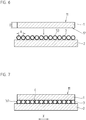
- FIGS. 6 and 7 illustrated third embodiment with respect to the first embodiment acts as a holding means only acting as a sheathing of the balls 3 layer 53 for stationary fixation of the balls 3 on the carrier 2 and for stationary fixation of the balls on scale 1.
- This serving can be realized by the balls 3 are mixed in a holding means, such as adhesive or photoresist, so that the balls 3 are distributed therein and this mixture is applied to the carrier 2.
- these can also be fixed in a carrier, for example in a film, with this prefabricated film then being placed on the carrier 2 and / or the scale 1.
- the stationary support between the balls 3 and the carrier 2 and the balls 3 and the scale 1 by adhesive in the form of adhesives, photoresist, solder material (eg glass solder), sintered layers or by cold bonding will be realized.
- an absolute coding can also be provided.
Description
Zur Messung der Relativlage zweier Maschinenteile ist an einem der Maschinenteile ein Maßstab zu befestigen und am anderen der zueinander beweglichen Maschinenteile eine Abtasteinheit. Bei der Positionsmessung wird eine Messteilung des Maßstabs von der Abtasteinheit abgetastet und positionsabhängige Abtastsignale generiert.To measure the relative position of two machine parts, a scale is to be attached to one of the machine parts, and a scanning unit is attached to the other of the mutually movable machine parts. In the position measurement, a measurement graduation of the scale is scanned by the scanning unit and position-dependent scanning signals are generated.
In der
Durch die Kombination Kugel und Feder ist eine Befestigung und Unterstützung nur im Randbereich des Maßstabs möglich, wodurch keine ebene Lagerung innerhalb des tatsächlichen Messbereichs des Maßstabs erreicht wird.The ball and spring combination allows attachment and support only at the edge of the scale, eliminating the need for leveling within the actual range of the scale.
In der
Aufgabe der Erfindung ist es, eine Anordnung mit einem an einem Träger befestigten Maßstab anzugeben, wobei der Maßstab am Träger stabil und driftfrei gehalten wird. Weiterhin soll die Befestigung möglichst einfach und mit kostengünstigen Mitteln ermöglicht werden.The object of the invention is to provide an arrangement with a scale attached to a support, wherein the scale is kept stable and drift-free on the support. Furthermore, the attachment should be possible as simple and inexpensive means possible.
Gelöst wird diese Aufgabe durch die im Anspruch 1 angegebene Anordnung.This object is achieved by the arrangement specified in
Demnach weist der Maßstab eine Messteilung auf und stützt sich über zweidimensional verteilt angeordnete Kugeln am Träger ab. Die Messteilung definiert auf einer Oberfläche des Maßstabs einen Messbereich und die der Messteilung gegenüberliegende Oberfläche des Maßstabs bildet eine Auflagefläche, welche die Kugeln kontaktiert. Die Haltekraft zwischen dem Träger und dem Maßstab wird aufgebracht, indem die Kugeln einerseits am Träger und andererseits am Maßstab unverrückbar befestigt sind. Diese ortsfesten Befestigungen sind jeweils durch Stoffschluss realisiert.Accordingly, the scale has a measuring graduation and is supported by two-dimensionally distributed balls arranged on the carrier. The measurement graduation defines a measurement area on a surface of the scale, and the surface of the scale opposite the measurement graduation forms a support surface which contacts the spheres. The holding force between the carrier and the scale is applied by the balls are fixed on the one hand on the carrier and on the other hand on the scale immovable. These fixed fasteners are each realized by material connection.
Für diese unverrückbare ortsfeste Befestigung der Kugeln dient ein Haltemittel, insbesondere ein Haftmittel, welches eine stoffschlüssige Befestigung der Kugeln bewirkt. Dieses Haltemittel ist vorzugsweise als Beschichtung ausgeführt, wobei es hierzu mehrere Möglichkeiten gibt. Die Schicht, in welcher die Kugeln ortsfest am Träger befestigt sind, kann auf dem Träger aufgebracht sein und / oder die Schicht ist in Form einer Umhüllung auf den Kugeln aufgebracht. Die Schicht, in welcher die Kugeln ortsfest am Maßstab befestigt sind, kann auf dem Maßstab aufgebracht sein und / oder die Schicht ist in Form einer Umhüllung auf den Kugeln aufgebracht. Im montierten Zustand sind diese Schichten von den Kugeln durchdrungen, so dass ein direkter Kontakt der Kugeln mit der Auflagefläche des Maßstabs und dem Träger vorhanden ist, ohne Zwischenschaltung von Schichtmaterial.For this immovable stationary attachment of the balls is a holding means, in particular an adhesive which causes a cohesive attachment of the balls. This holding means is preferably designed as a coating, wherein there are several possibilities for this purpose. The layer in which the balls are fixedly attached to the carrier can be applied to the carrier and / or the layer is applied in the form of an envelope on the balls. The layer in which the balls are fixedly attached to the scale may be applied to the scale and / or the layer is applied in the form of an envelope on the balls. In the assembled state, these layers are penetrated by the balls, so that a direct contact of the balls with the bearing surface of the scale and the carrier is present, without the interposition of layer material.
Besonders vorteilhaft ist die Verwendung eines Haftmittels, insbesondere Klebstoff, das bei der Aushärtung schrumpft und dieser Schrumpfungseffekt positiv genutzt wird, indem dadurch eine Haltekraft generiert wird, die als Zugfeder wirkt, wodurch die Auflagefläche des Maßstabs an die Kugeln gezogen wird.Particularly advantageous is the use of an adhesive, in particular adhesive, which shrinks during curing and this shrinkage effect is positively used, thereby generating a holding force acting as a tension spring, whereby the support surface of the scale is drawn to the balls.
Besonders vorteilhaft ist, wenn die Kugeln in einem gegenseitigen Mittenabstand angeordnet sind, der kleiner als die Dicke des Maßstabs ist.It is particularly advantageous if the balls are arranged at a mutual center distance which is smaller than the thickness of the scale.
Die Kugeln und die Mittel zur Befestigung, also die Haltemittel, sind derart angeordnet und ausgebildet, dass sich dazwischen Freiräume ausbilden, welche nach außen führende Kanäle bilden. Diese im Zwischenraum von Maßstab und Träger verlaufenden Kanäle korrespondieren mit dem Umgebungsmedium.The balls and the means for attachment, so the holding means are arranged and formed such that form between them free spaces, which form outwardly leading channels. These channels extending in the space between the scale and the carrier correspond to the surrounding medium.
Um Verspannungen zu vermeiden, ist es besonders vorteilhaft, wenn die Materialien von Träger und von Maßstab jeweils den gleichen thermischen Ausdehnungskoeffizienten aufweisen. Der Ausdehnungskoeffizient des Trägers und des Maßstabs ist vorzugsweise kleiner als 0,1 x 10⁻⁶K-1.In order to avoid tension, it is particularly advantageous if the materials of support and scale each have the same coefficient of thermal expansion. The coefficient of expansion of the carrier and the scale is preferably less than 0.1 × 10 -6 K -1 .
Die Kugeln bestehen aus einem Material, das auftretenden Druckkräften möglichst ohne Verformung standhält. Ein geeignetes Material ist beispielsweise Glas.The balls are made of a material that withstands occurring compressive forces as possible without deformation. A suitable material is for example glass.
Weitere vorteilhafte Ausbildungen der Erfindung sind in den abhängigen Ansprüchen angegeben.Further advantageous embodiments of the invention are specified in the dependent claims.
Die flächige Ebenheit - auch eines großflächigen Maßstabs - bleibt bei der erfindungsgemäßen Anordnung erhalten bzw. wird nicht gestört, da störende Medien sich in den durch die zwischen den Kugeln gebildeten Freiräumen ablagern können. Durch die erfindungsgemäße Maßnahme werden kurzperiodische Längenfehler in der Messteilungsebene vermieden und eine hohe Messgenauigkeit ist sichergestellt.The planar flatness - even of a large scale - is maintained in the arrangement according to the invention or is not disturbed, since disturbing media can be deposited in the spaces formed by the free spaces. By means of the measure according to the invention, short-periodic length errors in the measuring graduation plane are avoided and a high measuring accuracy is ensured.
Der Maßstab ist im Messbetrieb stabil am Träger befestigt, was eine hohe Steifigkeit in Messrichtung sowie senkrecht zur Messteilungsebene bedeutet.The scale is stably fixed to the carrier during measurement operation, which means high rigidity in the measuring direction and perpendicular to the graduation plane.
Ausführungsbeispiele der Erfindung werden anhand der Zeichnungen näher erläutert.Embodiments of the invention will be explained in more detail with reference to the drawings.
Es zeigen:
Figur 1- einen Träger mit Kugeln beim Aufsetzen eines Maßstabs nach einem ersten Ausführungsbeispiel im Querschnitt;
Figur 2- den am Träger gehaltenen Maßstab nach dem ersten Ausführungsbeispiel im Querschnitt;
Figur 3- eine Draufsicht auf die Anordnung gemäß
Figur 2 Figur 4- einen Träger mit Kugeln beim Aufsetzen eines Maßstabs nach einem zweiten Ausführungsbeispiel im Querschnitt;
- Figur 5
- den am Träger gehaltenen Maßstab nach dem zweiten Ausführungsbeispiel im Querschnitt;
- Figur 6
- einen Träger mit Kugeln beim Aufsetzen eines Maßstabs nach einem dritten Ausführungsbeispiel im Querschnitt, und
- Figur 7
- den am Träger gehaltenen Maßstab nach dem dritten Ausführungsbeispiel im Querschnitt.
- FIG. 1
- a carrier with balls in setting a scale according to a first embodiment in cross section;
- FIG. 2
- the scale held on the carrier according to the first embodiment in cross section;
- FIG. 3
- a plan view of the arrangement according to
FIG. 2 ; - FIG. 4
- a carrier with balls when setting a scale according to a second embodiment in cross section;
- FIG. 5
- the scale held on the carrier according to the second embodiment in cross section;
- FIG. 6
- a carrier with balls in setting a scale according to a third embodiment in cross section, and
- FIG. 7
- the scale held on the carrier according to the third embodiment in cross section.
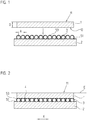
Anhand der
Auf der dem Träger 2 zugewandten Oberfläche 12 des Maßstabs 1 wird dieser durch Kugeln 3 unterstützt. Diese Kugeln 3 sind zweidimensional räumlich verteilt angeordnet, entweder geometrisch gleichmäßig in einem regelmäßigen Raster verteilt oder statistisch verteilt. Die Kugeln 3 sind mit einem gegenseitigen Mittenabstand A von kleiner der Dicke D des Maßstabs 1 angeordnet. Insbesondere sind die Kugeln 3 in einem gegenseitigen Mittenabstand A kleiner 1/10 der Dicke D des Maßstabs 1 angeordnet. Diese Bedingung ist an jeder Stelle der zweidimensionalen Verteilung der Kugeln 3, zumindest aber innerhalb des Messbereichs M, erfüllt. Der Messbereich M ist definiert durch den Bereich der Messteilung 11, der für die hochgenaue Positionsmessung genutzt wird. Die Dicke D des Maßstabs 1 ist der Abstand zwischen der Messteilungsebene E, in der die Messteilung 11 liegt, und der Auflagefläche 12, mit der er sich auf den Kugeln 3 abstützt.On the
Durch diese Maßnahme ist gewährleistet, dass alle Zug- und Druckspannungen, die durch die Befestigung eingebracht werden, derart räumlich hochfrequent sind, dass sich diese über die Dicke D des Maßstabs 1 abbauen und sich in der Messteilungsebene E nicht als Längenfehler auswirken. Durch die der Messteilung 11 direkt gegenüberliegende Unterstützung ist der Maßstab 1 im Messbetrieb stabil am Träger 2 befestigt, was eine hohe Steifigkeit in den Messrichtungen X und Y sowie senkrecht zur Messteilungsebene E bedeutet.By this measure, it is ensured that all tensile and compressive stresses that are introduced by the attachment, are spatially high frequency that they degrade over the thickness D of the
In
Die in
Typische Werte für die Dicke D des Maßstabs 1 liegen bei 0,5mm bis 15mm.Typical values for the thickness D of
Die Kugeln 3 bestehen aus einem Material, das auftretenden Druckkräften möglichst ohne Verformung standhält. Ein geeignetes Material ist beispielsweise Glas. In vorteilhafter Weise bestehen die Kugeln 3 aus einem Material, das den gleichen Ausdehnungskoeffizienten aufweist, wie der Maßstab 1.The
Die Kugeln 3 haben insbesondere einen Durchmesser zwischen 20 µm und 200 µm, typisch 50 µm. Die Toleranz der Kugeln bezüglich Durchmesser und Rundheit ist vorzugsweise kleiner 5 µm, d. h., bei einem Solldurchmesser von 50 µm haben die Kugeln 3 eine Abweichung von maximal ± 5 µm.The
Die eigentliche Befestigung des Maßstabs 1 am Träger 2 erfolgt bei allen Ausführungsbeispielen durch unverrückbare Befestigung der Kugeln 3 einerseits an dem Träger 2 und andererseits an dem Maßstab 1. Diese Befestigungen sind stoffschlüssige Verbindungen, also beispielsweise Kleben, Löten oder Schweißen.The actual attachment of the
Beim ersten Ausführungsbeispiel dient zur driftfreien Halterung der Kugeln 3 am Maßstab 1 und am Träger 2 ein Haltemittel in Form einer auf den Träger 2 aufgebrachten Schicht 51, in welcher die Kugeln 3 eingebettet sind und dadurch örtlich stabil am Träger 2 gebunden sind. Diese Schicht 51 ist ein Haftmittel, beispielsweise ein fest aushärtender Klebstoff, ein Fotolack oder ein Polymer und hat eine Dicke, die ein Bruchteil des Durchmessers der Kugeln 3 ist.In the first embodiment, drift-free mounting of the
Die Lagefixierung des Maßstabs 1 gegenüber der nun am Träger 2 lagefixierten Kugeln 3 erfolgt ebenfalls mit einem Haltemittel 53 in Form eines Haftmittels, beispielsweise in Form eines Klebstoffs oder eines anderen fest aushärtenden Materials, welches die Kugeln 3 umhüllt und haftend wirkt.The fixation of the
Die Kugeln 3 kontaktieren einerseits den Maßstab 1 auf seiner Unterseite, also der Auflagefläche 12 jeweils punktförmig und andererseits den Träger 2 ebenfalls punktförmig. Dadurch ist gewährleistet, dass die Ebenheit des Maßstabs 1 nicht durch andere Medien, beispielsweise dem Klebstoff, nachteilig beeinflusst wird. Die Haltemittel 51, 53 haben nur den Zweck, die Kugeln 3 ortsfest zu fixieren und die Haltekraft zwischen dem Träger 2 und dem Maßstab 1 zu generieren und aufrechtzuerhalten.The
Durch die Kugelform und die geeignete Wahl der Dicke der Schichten 51 und 53 ist gewährleistet, dass zwischen jeweils zwei Kugeln 3, auch wenn diese aneinander anstoßen, Freiräume 4 entstehen. Das Haltemittel 51, 53, also das Schichtmaterial, hat für die Aushärtung und auch die spätere Alterung ausreichend Volumen, ohne den Abstand zwischen dem Träger 2 und dem Maßstab 1 zu beeinflussen.Due to the spherical shape and the suitable choice of the thickness of the
Bei der zweidimensionalen Anordnung der Kugeln 3 stehen diese Freiräume 4 miteinander in Verbindung und bilden somit nach außen führende Kanäle. Durch diese Maßnahme kann die Luft über die gesamte Fläche des Maßstabs 1 über die Kanäle homogen nach außen in die Umgebung abgegeben werden, was eine gute Ebenheit des Maßstabs 1 bei der Montage und auch während des Messbetriebs sicherstellt.In the two-dimensional arrangement of the
Diese miteinander in Verbindung stehenden Freiräume 4 haben den Vorteil, dass bei dem Auflegen des Maßstabs 1 auf die Kugeln 3 Luft im Zwischenraum zwangskräftefrei entweichen kann. Weiterhin besteht die Möglichkeit, die Freiräume 4 als Kanäle zum Vakuum-Ansaugen des Maßstabs 1 zu nutzen. Dabei wird der Maßstab 1 auf die Kugeln 3 aufgelegt und eine Haltekraft durch Bilden von Unterdruck in den Freiräumen 3 eingeleitet, bis das Schichtmaterial vollständig ausgehärtet ist. Die nach außen führenden Freiräume 4 können auch genutzt werden, um den Zwischenraum zwischen den Kugeln 3 mit einem Medium zu spülen, um beispielsweise das Schichtmaterial gezielt zu beeinflussen oder zur Temperaturregelung. Anstelle von Unterdruck kann auch Überdruck angelegt werden oder ein das Schichtmaterial lösendes Medium eingebracht werden, um eine Demontage des Maßstabs 1 zu ermöglichen.These interconnected
Obige Ausführungen zu dem Träger 2, dem Maßstab 1 und der Messteilung 11 gelten auch bei den nachfolgenden Ausführungsbeispielen. Für diese Elemente werden deshalb bei allen Ausführungsbeispielen die gleichen Bezugszeichen verwendet.The above statements on the
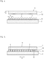
Das in den
Auch hier kontaktieren die Kugeln 3 einerseits den Maßstab 1 auf seiner Auflagefläche 12 jeweils punktförmig, durchstoßen bei dem Auflegen des Maßstabs 1 also die Schicht 52. Andererseits kontaktieren die Kugeln 3 den Träger 2 ebenfalls punktförmig. Dadurch ist gewährleistet, dass die Ebenheit des Maßstabs 1 nicht durch andere Medien, insbesondere dem Schichtmaterial, nachteilig beeinflusst wird. Die Haltemittel 51, 52 haben nur den Zweck, die Kugeln 3 ortsfest zu fixieren und die Haltekraft zwischen dem Träger 2 und dem Maßstab 1 zu generieren und aufrechtzuerhalten.Here too, the
Durch die Kugelform und die geeignete Wahl der Dicke der Schichten 51 und 52 ist gewährleistet, dass zwischen jeweils zwei Kugeln 3, auch wenn diese aneinander anstoßen, Freiräume 4 entstehen. Das Haltemittel 51, 52, also das Schichtmaterial hat für die Aushärtung und auch die spätere Alterung ausreichend Volumen, ohne den Abstand zwischen dem Träger 2 und dem Maßstab 1 zu beeinflussen.The spherical shape and the suitable choice of the thickness of the
Bei der zweidimensionalen Anordnung der Kugeln 3 stehen diese Freiräume 4 miteinander in Verbindung und bilden somit nach außen führende Kanäle. Durch diese Maßnahme kann die Luft über die gesamte Fläche des Maßstabs 1 über die Kanäle homogen nach außen in die Umgebung abgegeben werden, was eine gute Ebenheit des Maßstabs 1 bei der Montage und auch während des Messbetriebs sicherstellt.In the two-dimensional arrangement of the
Der Unterschied des in den
Zur besseren Handhabung und Verteilung der Kugeln 3 auf dem Träger 2 können diese auch in einem Träger, beispielsweise in einer Folie, fixiert sein, wobei diese so vorgefertigte Folie dann auf dem Träger 2 und / oder dem Maßstab 1 aufgelegt wird.For better handling and distribution of the
Bei allen Ausführungsbeispielen kann die ortsfeste Halterung zwischen den Kugeln 3 und dem Träger 2 sowie den Kugeln 3 und dem Maßstab 1 durch Haftmittel in Form von Klebstoffen, von Fotolack, von Lotmaterial (z. B. Glaslot), von Sinterschichten oder durch Cold-Bonding realisiert werden.In all embodiments, the stationary support between the
Anstelle oder zusätzlich zu der inkrementalen Messteilung 11 kann auch eine absolute Codierung vorgesehen werden.Instead of or in addition to the
Claims (8)
- Arrangement having a scale (1) fastened to a carrier (2), wherein the scale (1) has a measurement graduation (11) and is supported on balls (3), arranged in a two-dimensionally distributed manner, on the carrier (2), said balls (3) being arranged on the opposite side from the measurement graduation (11), defining a measuring region (M), of the scale (1), wherein the balls (3) are fastened immovably to the carrier (2) on the one hand and to the scale (1) on the other hand.
- Arrangement according to Claim 1, characterized in that the balls (3) are held immovably in their position on the carrier (2) and on the scale (1) via holding means (51, 52, 53), wherein the holding means (51, 52, 53) brings about a material bond between the balls (3) and the carrier (2) and between the balls (3) and the scale (1).
- Arrangement according to Claim 2, characterized in that the holding means is a first layer (51) arranged on the carrier (2) and a second layer (52) arranged on the scale (1), the balls (3) being embedded in said layers.
- Arrangement according to either of Claims 2 and 3, characterized in that the holding means is a layer (3) enveloping the balls (3).
- Arrangement according to one of the preceding claims, characterized in that the balls (3) are arranged at a mutual centre-to-centre distance (A) which is less than the thickness (D) of the scale (1).
- Arrangement according to one of the preceding claims, characterized in that the balls (3) are arranged and fastened such that they have mutual clearances (4) which form outwardly leading channels.
- Arrangement according to one of the preceding claims, characterized in that the materials of the carrier (2) and of the scale (1) have the same coefficient of thermal expansion.
- Arrangement according to Claim 7, characterized in that the coefficient of expansion of the carrier (2) and of the scale (1) is less than 1.5×10⁻⁶K-1, preferably less than 0.1×10⁻⁶K-1.
Applications Claiming Priority (1)
| Application Number | Priority Date | Filing Date | Title |
|---|---|---|---|
| DE102009047120A DE102009047120A1 (en) | 2009-11-25 | 2009-11-25 | Arrangement with a scale attached to a support |
Publications (3)
| Publication Number | Publication Date |
|---|---|
| EP2348288A2 EP2348288A2 (en) | 2011-07-27 |
| EP2348288A3 EP2348288A3 (en) | 2016-06-15 |
| EP2348288B1 true EP2348288B1 (en) | 2016-12-28 |
Family
ID=43901884
Family Applications (1)
| Application Number | Title | Priority Date | Filing Date |
|---|---|---|---|
| EP10174572.7A Active EP2348288B1 (en) | 2009-11-25 | 2010-08-31 | Assembly with a measuring rod attached to a holder |
Country Status (6)
| Country | Link |
|---|---|
| US (1) | US8234793B2 (en) |
| EP (1) | EP2348288B1 (en) |
| JP (1) | JP5579024B2 (en) |
| CN (1) | CN102095372B (en) |
| DE (1) | DE102009047120A1 (en) |
| ES (1) | ES2613038T3 (en) |
Families Citing this family (8)
| Publication number | Priority date | Publication date | Assignee | Title |
|---|---|---|---|---|
| DE102009002142A1 (en) * | 2009-04-02 | 2010-10-07 | Dr. Johannes Heidenhain Gmbh | An assembly with a scale attached to a support and method of holding a scale on a support |
| DE102009045515B3 (en) * | 2009-10-09 | 2011-03-03 | Dreier Lasermesstechnik Gmbh | Device for checking the accuracy of machine tools and measuring devices |
| KR101648200B1 (en) | 2009-10-22 | 2016-08-12 | 삼성전자주식회사 | Image sensor and method of manufacturing the same |
| DE102009047120A1 (en) * | 2009-11-25 | 2011-05-26 | Dr. Johannes Heidenhain Gmbh | Arrangement with a scale attached to a support |
| DE102013220190B4 (en) * | 2013-10-07 | 2021-08-12 | Dr. Johannes Heidenhain Gmbh | Measuring graduation and photoelectric position measuring device with this measuring graduation |
| US9612107B2 (en) * | 2014-06-10 | 2017-04-04 | Faro Technologies, Inc. | Length artifact and method of measurement |
| EP3023742B1 (en) * | 2014-11-19 | 2017-01-11 | Dr. Johannes Heidenhain GmbH | Assembly comprising a measurement scale attached to a support |
| IT201900003817A1 (en) * | 2019-03-15 | 2020-09-15 | Parpas S P A | LINEAR ENCODER |
Family Cites Families (17)
| Publication number | Priority date | Publication date | Assignee | Title |
|---|---|---|---|---|
| DE3635511A1 (en) * | 1986-10-18 | 1988-04-28 | Zeiss Carl Fa | BRACKET FOR MEASURING AND SHAPED EMBODIMENT |
| JP2683148B2 (en) * | 1990-09-04 | 1997-11-26 | アルプス電気株式会社 | Transparent touch switch |
| JPH06324221A (en) * | 1993-05-11 | 1994-11-25 | Nippon Telegr & Teleph Corp <Ntt> | Optical fiber array |
| DE4406799C2 (en) * | 1994-03-02 | 1997-11-06 | Heidenhain Gmbh Dr Johannes | Position measuring device |
| US5778553A (en) * | 1996-07-03 | 1998-07-14 | Hollensbe; Homer D. | Dimension transfer tool |
| JP4218916B2 (en) * | 1999-07-27 | 2009-02-04 | フジノン株式会社 | Method of manufacturing support device for object to be measured |
| US6964113B2 (en) * | 2001-03-06 | 2005-11-15 | Faro Laser Trackers, Llc | Scale-bar artifact and methods of use |
| JP4477440B2 (en) * | 2004-07-15 | 2010-06-09 | 株式会社ミツトヨ | Scale elastic holding method and position measuring device |
| EP1742023A1 (en) * | 2005-07-06 | 2007-01-10 | Schneeberger Holding AG | Linear motion guide with apparatus for measuring the position |
| US7707739B2 (en) * | 2005-11-04 | 2010-05-04 | Dr. Johannes Heidenhain Gmbh | Method for attaching a scale to a carrier, a scale, and carrier having a scale |
| DE102005053088A1 (en) * | 2005-11-04 | 2007-05-10 | Dr. Johannes Heidenhain Gmbh | Scale attaching method for use in support, involves providing surfaces with adhesives between scale and support, and forming wringing surfaces in direct proximity to dosing channel, where wringing surfaces are separated from one another |
| ES2535851T3 (en) * | 2005-11-04 | 2015-05-18 | Dr. Johannes Heidenhain Gmbh | Procedure for fixing a measurement scale on a support, adapted measurement scale as well as support with this measurement scale |
| EP2002216B1 (en) * | 2006-03-29 | 2015-07-08 | Dr. Johannes Heidenhain GmbH | Method for holding a scale on a carrier and arrangement having a carrier and a scale |
| US8007609B2 (en) * | 2007-10-31 | 2011-08-30 | Symphony Acoustics, Inc. | Parallel plate arrangement and method of formation |
| DE102009002142A1 (en) * | 2009-04-02 | 2010-10-07 | Dr. Johannes Heidenhain Gmbh | An assembly with a scale attached to a support and method of holding a scale on a support |
| US8051575B2 (en) * | 2009-10-20 | 2011-11-08 | Faro Technologies, Inc. | Mounted scale bar |
| DE102009047120A1 (en) * | 2009-11-25 | 2011-05-26 | Dr. Johannes Heidenhain Gmbh | Arrangement with a scale attached to a support |
-
2009
- 2009-11-25 DE DE102009047120A patent/DE102009047120A1/en not_active Withdrawn
-
2010
- 2010-08-31 ES ES10174572.7T patent/ES2613038T3/en active Active
- 2010-08-31 EP EP10174572.7A patent/EP2348288B1/en active Active
- 2010-11-12 JP JP2010254042A patent/JP5579024B2/en active Active
- 2010-11-16 US US12/927,488 patent/US8234793B2/en active Active
- 2010-11-25 CN CN201010562650.7A patent/CN102095372B/en active Active
Non-Patent Citations (1)
| Title |
|---|
| None * |
Also Published As
| Publication number | Publication date |
|---|---|
| CN102095372B (en) | 2015-09-30 |
| JP2011145281A (en) | 2011-07-28 |
| EP2348288A3 (en) | 2016-06-15 |
| CN102095372A (en) | 2011-06-15 |
| ES2613038T3 (en) | 2017-05-22 |
| JP5579024B2 (en) | 2014-08-27 |
| EP2348288A2 (en) | 2011-07-27 |
| US20110119945A1 (en) | 2011-05-26 |
| US8234793B2 (en) | 2012-08-07 |
| DE102009047120A1 (en) | 2011-05-26 |
Similar Documents
| Publication | Publication Date | Title |
|---|---|---|
| EP2348288B1 (en) | Assembly with a measuring rod attached to a holder | |
| EP3026389B1 (en) | Length measuring device | |
| EP2002216B1 (en) | Method for holding a scale on a carrier and arrangement having a carrier and a scale | |
| EP2302332A2 (en) | Length measuring device | |
| EP2414783B1 (en) | Device with a scale fixed to a support and procedure for fixing a scale to a support | |
| WO2002012906A1 (en) | Micromechanical component | |
| WO2000067310A1 (en) | Microelectronic subassembly | |
| AT515951B1 (en) | positioning | |
| EP1783463A1 (en) | Method for fixing a scale to a support, thereto adapted scale and support with such a scale | |
| WO2017140313A1 (en) | Sensor and sensor element | |
| EP1050070B1 (en) | Exposure apparatus with holding device for a substrate | |
| DE102012104552B4 (en) | Device for dynamically exciting a component and test stand with the same | |
| EP3023742B1 (en) | Assembly comprising a measurement scale attached to a support | |
| EP3477263A1 (en) | Assembly with a gauge attached to a carrier | |
| EP0975940B1 (en) | Linear force transducer with two films and two punches | |
| EP4145083B1 (en) | Optical receiving unit | |
| EP1852674A1 (en) | Measuring device for determining the relative displacement between two components | |
| EP3078940B1 (en) | Length measuring device | |
| DE102007002772A1 (en) | Measurement rod holding method, involves creating electrical voltage between electrodes of measurement rod and carrier, and forming difference of potential between rod and carrier to generate holding force for electrostatic clamp | |
| EP3977059B1 (en) | Support member for a precision device, support frame for a precision device and precision device comprising such a support member or support frame | |
| EP3214479A1 (en) | Apparatus for deforming an optical element and optical element comprising said apparatus | |
| DE102017131263A1 (en) | Method for producing a measuring device | |
| DE102010025633B4 (en) | Device for measuring small and large forces | |
| WO2022078578A1 (en) | Pressure-measuring cell and method for producing a pressure-measuring cell | |
| DE102008030985A1 (en) | Measuring arrangement for use in e.g. angle measuring system, to determine position of machine part of machine tool, has screw acting on flange region by intermediate element with thermal expansion coefficient larger than region's materials |
Legal Events
| Date | Code | Title | Description |
|---|---|---|---|
| PUAI | Public reference made under article 153(3) epc to a published international application that has entered the european phase |
Free format text: ORIGINAL CODE: 0009012 |
|
| AK | Designated contracting states |
Kind code of ref document: A2 Designated state(s): AL AT BE BG CH CY CZ DE DK EE ES FI FR GB GR HR HU IE IS IT LI LT LU LV MC MK MT NL NO PL PT RO SE SI SK SM TR |
|
| AX | Request for extension of the european patent |
Extension state: BA ME RS |
|
| PUAL | Search report despatched |
Free format text: ORIGINAL CODE: 0009013 |
|
| AK | Designated contracting states |
Kind code of ref document: A3 Designated state(s): AL AT BE BG CH CY CZ DE DK EE ES FI FR GB GR HR HU IE IS IT LI LT LU LV MC MK MT NL NO PL PT RO SE SI SK SM TR |
|
| AX | Request for extension of the european patent |
Extension state: BA ME RS |
|
| RIC1 | Information provided on ipc code assigned before grant |
Ipc: G01D 5/347 20060101AFI20160509BHEP |
|
| 17P | Request for examination filed |
Effective date: 20160518 |
|
| RBV | Designated contracting states (corrected) |
Designated state(s): AL AT BE BG CH CY CZ DE DK EE ES FI FR GB GR HR HU IE IS IT LI LT LU LV MC MK MT NL NO PL PT RO SE SI SK SM TR |
|
| GRAP | Despatch of communication of intention to grant a patent |
Free format text: ORIGINAL CODE: EPIDOSNIGR1 |
|
| INTG | Intention to grant announced |
Effective date: 20160921 |
|
| RIN1 | Information on inventor provided before grant (corrected) |
Inventor name: SPECKBACHER, PETER Inventor name: WEIDMANN, JOSEF |
|
| GRAS | Grant fee paid |
Free format text: ORIGINAL CODE: EPIDOSNIGR3 |
|
| GRAA | (expected) grant |
Free format text: ORIGINAL CODE: 0009210 |
|
| AK | Designated contracting states |
Kind code of ref document: B1 Designated state(s): AL AT BE BG CH CY CZ DE DK EE ES FI FR GB GR HR HU IE IS IT LI LT LU LV MC MK MT NL NO PL PT RO SE SI SK SM TR |
|
| REG | Reference to a national code |
Ref country code: GB Ref legal event code: FG4D Free format text: NOT ENGLISH |
|
| REG | Reference to a national code |
Ref country code: CH Ref legal event code: EP Ref country code: CH Ref legal event code: NV Representative=s name: ICB INGENIEURS CONSEILS EN BREVETS SA, CH |
|
| REG | Reference to a national code |
Ref country code: AT Ref legal event code: REF Ref document number: 857699 Country of ref document: AT Kind code of ref document: T Effective date: 20170115 |
|
| REG | Reference to a national code |
Ref country code: IE Ref legal event code: FG4D Free format text: LANGUAGE OF EP DOCUMENT: GERMAN |
|
| REG | Reference to a national code |
Ref country code: DE Ref legal event code: R096 Ref document number: 502010012948 Country of ref document: DE |
|
| PG25 | Lapsed in a contracting state [announced via postgrant information from national office to epo] |
Ref country code: LV Free format text: LAPSE BECAUSE OF FAILURE TO SUBMIT A TRANSLATION OF THE DESCRIPTION OR TO PAY THE FEE WITHIN THE PRESCRIBED TIME-LIMIT Effective date: 20161228 |
|
| REG | Reference to a national code |
Ref country code: LT Ref legal event code: MG4D |
|
| PG25 | Lapsed in a contracting state [announced via postgrant information from national office to epo] |
Ref country code: LT Free format text: LAPSE BECAUSE OF FAILURE TO SUBMIT A TRANSLATION OF THE DESCRIPTION OR TO PAY THE FEE WITHIN THE PRESCRIBED TIME-LIMIT Effective date: 20161228 Ref country code: NO Free format text: LAPSE BECAUSE OF FAILURE TO SUBMIT A TRANSLATION OF THE DESCRIPTION OR TO PAY THE FEE WITHIN THE PRESCRIBED TIME-LIMIT Effective date: 20170328 Ref country code: GR Free format text: LAPSE BECAUSE OF FAILURE TO SUBMIT A TRANSLATION OF THE DESCRIPTION OR TO PAY THE FEE WITHIN THE PRESCRIBED TIME-LIMIT Effective date: 20170329 Ref country code: SE Free format text: LAPSE BECAUSE OF FAILURE TO SUBMIT A TRANSLATION OF THE DESCRIPTION OR TO PAY THE FEE WITHIN THE PRESCRIBED TIME-LIMIT Effective date: 20161228 |
|
| REG | Reference to a national code |
Ref country code: NL Ref legal event code: MP Effective date: 20161228 |
|
| REG | Reference to a national code |
Ref country code: ES Ref legal event code: FG2A Ref document number: 2613038 Country of ref document: ES Kind code of ref document: T3 Effective date: 20170522 |
|
| PG25 | Lapsed in a contracting state [announced via postgrant information from national office to epo] |
Ref country code: HR Free format text: LAPSE BECAUSE OF FAILURE TO SUBMIT A TRANSLATION OF THE DESCRIPTION OR TO PAY THE FEE WITHIN THE PRESCRIBED TIME-LIMIT Effective date: 20161228 Ref country code: FI Free format text: LAPSE BECAUSE OF FAILURE TO SUBMIT A TRANSLATION OF THE DESCRIPTION OR TO PAY THE FEE WITHIN THE PRESCRIBED TIME-LIMIT Effective date: 20161228 |
|
| PG25 | Lapsed in a contracting state [announced via postgrant information from national office to epo] |
Ref country code: NL Free format text: LAPSE BECAUSE OF FAILURE TO SUBMIT A TRANSLATION OF THE DESCRIPTION OR TO PAY THE FEE WITHIN THE PRESCRIBED TIME-LIMIT Effective date: 20161228 |
|
| PG25 | Lapsed in a contracting state [announced via postgrant information from national office to epo] |
Ref country code: EE Free format text: LAPSE BECAUSE OF FAILURE TO SUBMIT A TRANSLATION OF THE DESCRIPTION OR TO PAY THE FEE WITHIN THE PRESCRIBED TIME-LIMIT Effective date: 20161228 Ref country code: SK Free format text: LAPSE BECAUSE OF FAILURE TO SUBMIT A TRANSLATION OF THE DESCRIPTION OR TO PAY THE FEE WITHIN THE PRESCRIBED TIME-LIMIT Effective date: 20161228 Ref country code: CZ Free format text: LAPSE BECAUSE OF FAILURE TO SUBMIT A TRANSLATION OF THE DESCRIPTION OR TO PAY THE FEE WITHIN THE PRESCRIBED TIME-LIMIT Effective date: 20161228 Ref country code: IS Free format text: LAPSE BECAUSE OF FAILURE TO SUBMIT A TRANSLATION OF THE DESCRIPTION OR TO PAY THE FEE WITHIN THE PRESCRIBED TIME-LIMIT Effective date: 20170428 Ref country code: RO Free format text: LAPSE BECAUSE OF FAILURE TO SUBMIT A TRANSLATION OF THE DESCRIPTION OR TO PAY THE FEE WITHIN THE PRESCRIBED TIME-LIMIT Effective date: 20161228 |
|
| PG25 | Lapsed in a contracting state [announced via postgrant information from national office to epo] |
Ref country code: SM Free format text: LAPSE BECAUSE OF FAILURE TO SUBMIT A TRANSLATION OF THE DESCRIPTION OR TO PAY THE FEE WITHIN THE PRESCRIBED TIME-LIMIT Effective date: 20161228 Ref country code: PT Free format text: LAPSE BECAUSE OF FAILURE TO SUBMIT A TRANSLATION OF THE DESCRIPTION OR TO PAY THE FEE WITHIN THE PRESCRIBED TIME-LIMIT Effective date: 20170428 Ref country code: PL Free format text: LAPSE BECAUSE OF FAILURE TO SUBMIT A TRANSLATION OF THE DESCRIPTION OR TO PAY THE FEE WITHIN THE PRESCRIBED TIME-LIMIT Effective date: 20161228 Ref country code: BG Free format text: LAPSE BECAUSE OF FAILURE TO SUBMIT A TRANSLATION OF THE DESCRIPTION OR TO PAY THE FEE WITHIN THE PRESCRIBED TIME-LIMIT Effective date: 20170328 |
|
| REG | Reference to a national code |
Ref country code: DE Ref legal event code: R097 Ref document number: 502010012948 Country of ref document: DE |
|
| PLBE | No opposition filed within time limit |
Free format text: ORIGINAL CODE: 0009261 |
|
| STAA | Information on the status of an ep patent application or granted ep patent |
Free format text: STATUS: NO OPPOSITION FILED WITHIN TIME LIMIT |
|
| PG25 | Lapsed in a contracting state [announced via postgrant information from national office to epo] |
Ref country code: DK Free format text: LAPSE BECAUSE OF FAILURE TO SUBMIT A TRANSLATION OF THE DESCRIPTION OR TO PAY THE FEE WITHIN THE PRESCRIBED TIME-LIMIT Effective date: 20161228 |
|
| 26N | No opposition filed |
Effective date: 20170929 |
|
| PG25 | Lapsed in a contracting state [announced via postgrant information from national office to epo] |
Ref country code: SI Free format text: LAPSE BECAUSE OF FAILURE TO SUBMIT A TRANSLATION OF THE DESCRIPTION OR TO PAY THE FEE WITHIN THE PRESCRIBED TIME-LIMIT Effective date: 20161228 |
|
| PG25 | Lapsed in a contracting state [announced via postgrant information from national office to epo] |
Ref country code: MC Free format text: LAPSE BECAUSE OF FAILURE TO SUBMIT A TRANSLATION OF THE DESCRIPTION OR TO PAY THE FEE WITHIN THE PRESCRIBED TIME-LIMIT Effective date: 20161228 |
|
| REG | Reference to a national code |
Ref country code: FR Ref legal event code: ST Effective date: 20180430 |
|
| REG | Reference to a national code |
Ref country code: IE Ref legal event code: MM4A |
|
| REG | Reference to a national code |
Ref country code: BE Ref legal event code: MM Effective date: 20170831 |
|
| PG25 | Lapsed in a contracting state [announced via postgrant information from national office to epo] |
Ref country code: LU Free format text: LAPSE BECAUSE OF NON-PAYMENT OF DUE FEES Effective date: 20170831 |
|
| PG25 | Lapsed in a contracting state [announced via postgrant information from national office to epo] |
Ref country code: IE Free format text: LAPSE BECAUSE OF NON-PAYMENT OF DUE FEES Effective date: 20170831 |
|
| PG25 | Lapsed in a contracting state [announced via postgrant information from national office to epo] |
Ref country code: BE Free format text: LAPSE BECAUSE OF NON-PAYMENT OF DUE FEES Effective date: 20170831 Ref country code: FR Free format text: LAPSE BECAUSE OF NON-PAYMENT OF DUE FEES Effective date: 20170831 |
|
| PG25 | Lapsed in a contracting state [announced via postgrant information from national office to epo] |
Ref country code: MT Free format text: LAPSE BECAUSE OF FAILURE TO SUBMIT A TRANSLATION OF THE DESCRIPTION OR TO PAY THE FEE WITHIN THE PRESCRIBED TIME-LIMIT Effective date: 20161228 |
|
| REG | Reference to a national code |
Ref country code: AT Ref legal event code: MM01 Ref document number: 857699 Country of ref document: AT Kind code of ref document: T Effective date: 20170831 |
|
| PG25 | Lapsed in a contracting state [announced via postgrant information from national office to epo] |
Ref country code: AT Free format text: LAPSE BECAUSE OF NON-PAYMENT OF DUE FEES Effective date: 20170831 |
|
| PG25 | Lapsed in a contracting state [announced via postgrant information from national office to epo] |
Ref country code: HU Free format text: LAPSE BECAUSE OF FAILURE TO SUBMIT A TRANSLATION OF THE DESCRIPTION OR TO PAY THE FEE WITHIN THE PRESCRIBED TIME-LIMIT; INVALID AB INITIO Effective date: 20100831 |
|
| PG25 | Lapsed in a contracting state [announced via postgrant information from national office to epo] |
Ref country code: CY Free format text: LAPSE BECAUSE OF NON-PAYMENT OF DUE FEES Effective date: 20161228 |
|
| PG25 | Lapsed in a contracting state [announced via postgrant information from national office to epo] |
Ref country code: MK Free format text: LAPSE BECAUSE OF FAILURE TO SUBMIT A TRANSLATION OF THE DESCRIPTION OR TO PAY THE FEE WITHIN THE PRESCRIBED TIME-LIMIT Effective date: 20161228 |
|
| PG25 | Lapsed in a contracting state [announced via postgrant information from national office to epo] |
Ref country code: TR Free format text: LAPSE BECAUSE OF FAILURE TO SUBMIT A TRANSLATION OF THE DESCRIPTION OR TO PAY THE FEE WITHIN THE PRESCRIBED TIME-LIMIT Effective date: 20161228 |
|
| PG25 | Lapsed in a contracting state [announced via postgrant information from national office to epo] |
Ref country code: AL Free format text: LAPSE BECAUSE OF FAILURE TO SUBMIT A TRANSLATION OF THE DESCRIPTION OR TO PAY THE FEE WITHIN THE PRESCRIBED TIME-LIMIT Effective date: 20161228 |
|
| PGFP | Annual fee paid to national office [announced via postgrant information from national office to epo] |
Ref country code: IT Payment date: 20230825 Year of fee payment: 14 Ref country code: GB Payment date: 20230822 Year of fee payment: 14 Ref country code: CH Payment date: 20230902 Year of fee payment: 14 |
|
| PGFP | Annual fee paid to national office [announced via postgrant information from national office to epo] |
Ref country code: DE Payment date: 20230821 Year of fee payment: 14 |
|
| PGFP | Annual fee paid to national office [announced via postgrant information from national office to epo] |
Ref country code: ES Payment date: 20231027 Year of fee payment: 14 |