EP3023742B1 - Assembly comprising a measurement scale attached to a support - Google Patents
Assembly comprising a measurement scale attached to a support Download PDFInfo
- Publication number
- EP3023742B1 EP3023742B1 EP14193790.4A EP14193790A EP3023742B1 EP 3023742 B1 EP3023742 B1 EP 3023742B1 EP 14193790 A EP14193790 A EP 14193790A EP 3023742 B1 EP3023742 B1 EP 3023742B1
- Authority
- EP
- European Patent Office
- Prior art keywords
- layer
- spacers
- support
- measurement scale
- measuring
- Prior art date
- Legal status (The legal status is an assumption and is not a legal conclusion. Google has not performed a legal analysis and makes no representation as to the accuracy of the status listed.)
- Active
Links
- 238000005259 measurement Methods 0.000 title claims description 22
- 239000000463 material Substances 0.000 claims description 48
- 125000006850 spacer group Chemical group 0.000 claims description 28
- 239000007788 liquid Substances 0.000 claims description 6
- 239000011521 glass Substances 0.000 claims description 3
- 238000005096 rolling process Methods 0.000 claims description 2
- 230000001419 dependent effect Effects 0.000 description 3
- 239000012530 fluid Substances 0.000 description 3
- 239000011248 coating agent Substances 0.000 description 2
- 238000000576 coating method Methods 0.000 description 2
- 239000002241 glass-ceramic Substances 0.000 description 2
- 230000002401 inhibitory effect Effects 0.000 description 2
- 239000002184 metal Substances 0.000 description 2
- 229910052751 metal Inorganic materials 0.000 description 2
- 238000009736 wetting Methods 0.000 description 2
- 229910001374 Invar Inorganic materials 0.000 description 1
- 239000006094 Zerodur Substances 0.000 description 1
- 239000000853 adhesive Substances 0.000 description 1
- 230000001070 adhesive effect Effects 0.000 description 1
- 230000002411 adverse Effects 0.000 description 1
- 239000000919 ceramic Substances 0.000 description 1
- 238000006073 displacement reaction Methods 0.000 description 1
- 230000000694 effects Effects 0.000 description 1
- 239000000314 lubricant Substances 0.000 description 1
- 150000002739 metals Chemical class 0.000 description 1
- 238000005204 segregation Methods 0.000 description 1
- 229920002545 silicone oil Polymers 0.000 description 1
- 238000009827 uniform distribution Methods 0.000 description 1
Images

Classifications
-
- G—PHYSICS
- G01—MEASURING; TESTING
- G01D—MEASURING NOT SPECIALLY ADAPTED FOR A SPECIFIC VARIABLE; ARRANGEMENTS FOR MEASURING TWO OR MORE VARIABLES NOT COVERED IN A SINGLE OTHER SUBCLASS; TARIFF METERING APPARATUS; MEASURING OR TESTING NOT OTHERWISE PROVIDED FOR
- G01D5/00—Mechanical means for transferring the output of a sensing member; Means for converting the output of a sensing member to another variable where the form or nature of the sensing member does not constrain the means for converting; Transducers not specially adapted for a specific variable
- G01D5/12—Mechanical means for transferring the output of a sensing member; Means for converting the output of a sensing member to another variable where the form or nature of the sensing member does not constrain the means for converting; Transducers not specially adapted for a specific variable using electric or magnetic means
- G01D5/244—Mechanical means for transferring the output of a sensing member; Means for converting the output of a sensing member to another variable where the form or nature of the sensing member does not constrain the means for converting; Transducers not specially adapted for a specific variable using electric or magnetic means influencing characteristics of pulses or pulse trains; generating pulses or pulse trains
- G01D5/24428—Error prevention
- G01D5/24433—Error prevention by mechanical means
- G01D5/24442—Error prevention by mechanical means by mounting means
-
- G—PHYSICS
- G01—MEASURING; TESTING
- G01D—MEASURING NOT SPECIALLY ADAPTED FOR A SPECIFIC VARIABLE; ARRANGEMENTS FOR MEASURING TWO OR MORE VARIABLES NOT COVERED IN A SINGLE OTHER SUBCLASS; TARIFF METERING APPARATUS; MEASURING OR TESTING NOT OTHERWISE PROVIDED FOR
- G01D5/00—Mechanical means for transferring the output of a sensing member; Means for converting the output of a sensing member to another variable where the form or nature of the sensing member does not constrain the means for converting; Transducers not specially adapted for a specific variable
- G01D5/26—Mechanical means for transferring the output of a sensing member; Means for converting the output of a sensing member to another variable where the form or nature of the sensing member does not constrain the means for converting; Transducers not specially adapted for a specific variable characterised by optical transfer means, i.e. using infrared, visible, or ultraviolet light
- G01D5/32—Mechanical means for transferring the output of a sensing member; Means for converting the output of a sensing member to another variable where the form or nature of the sensing member does not constrain the means for converting; Transducers not specially adapted for a specific variable characterised by optical transfer means, i.e. using infrared, visible, or ultraviolet light with attenuation or whole or partial obturation of beams of light
- G01D5/34—Mechanical means for transferring the output of a sensing member; Means for converting the output of a sensing member to another variable where the form or nature of the sensing member does not constrain the means for converting; Transducers not specially adapted for a specific variable characterised by optical transfer means, i.e. using infrared, visible, or ultraviolet light with attenuation or whole or partial obturation of beams of light the beams of light being detected by photocells
- G01D5/347—Mechanical means for transferring the output of a sensing member; Means for converting the output of a sensing member to another variable where the form or nature of the sensing member does not constrain the means for converting; Transducers not specially adapted for a specific variable characterised by optical transfer means, i.e. using infrared, visible, or ultraviolet light with attenuation or whole or partial obturation of beams of light the beams of light being detected by photocells using displacement encoding scales
- G01D5/34707—Scales; Discs, e.g. fixation, fabrication, compensation
-
- G—PHYSICS
- G01—MEASURING; TESTING
- G01B—MEASURING LENGTH, THICKNESS OR SIMILAR LINEAR DIMENSIONS; MEASURING ANGLES; MEASURING AREAS; MEASURING IRREGULARITIES OF SURFACES OR CONTOURS
- G01B5/00—Measuring arrangements characterised by the use of mechanical techniques
- G01B5/0011—Arrangements for eliminating or compensation of measuring errors due to temperature or weight
- G01B5/0014—Arrangements for eliminating or compensation of measuring errors due to temperature or weight due to temperature
Definitions
- the present invention relates to an arrangement with a measuring embodiment attached to a carrier according to the preamble of claim 1.
- a material measure is to be attached to one of the machine parts, and a scanning unit is attached to the other of the mutually movable machine parts.
- a measurement graduation of the material measure is scanned by the scanning unit and position-dependent scanning signals are generated.
- the EP 0 416 391 A2 discloses an assembly having a scale attached to a support, wherein the attachment is by means of a liquid film and the measuring scale is drawn by the capillary action of the liquid film against a mounting surface of the carrier.
- EP 0 264 801 B1 is a material measure mounted on a support by this is supported on balls.
- the balls are mounted in a rollable manner in small areas.
- the holding force between the material measure and the carrier is initiated by springs.
- the combination ball and spring attachment and support only in the edge region of the measuring scale is possible, whereby no flat storage within the actual measuring range of the measuring scale is possible.
- the object of the invention is to provide an arrangement with a measuring standard attached to a carrier, wherein the material measure is kept as drift-free and temperature-stable in its position, so that a reproducible position measurement is possible.
- the position-measuring device shown comprises an arrangement of a measuring standard 1 and a scanning unit 2 arranged on a carrier 3.
- the scanning unit 2 is fastened to an object 100 which is movable relative to the carrier 3 in the measuring direction X.
- the material measure 1 has a non-contact scanned by the scanning unit 2 measuring graduation 11.
- the measuring graduation 1 is preferably made of a material with negligible thermal expansion coefficient, in particular with a thermal expansion coefficient a in the temperature range of 0 ° to 50 ° smaller than 1.5 x 10 -6 K -1 , but in particular smaller than 0.1 x 10th -6 K -1 .
- Such materials are glass or glass ceramic (eg ZERODUR) or metals such as Invar.
- the measuring graduation 11 is an incremental graduation, which is scanned photoelectrically during the position measurement in measuring directions X by the scanning unit 2 for the purpose of generating position-dependent scanning signals.
- the measuring graduation 11 may be a reflective amplitude grating or a phase grating, which serves in a known manner for high-precision interferential position measurement.
- the material measure 1 is attached to the carrier 3.
- This carrier 3 is usually made of a material whose coefficient of expansion from the coefficient of expansion of the material measure 1 deviates. For this reason, it is necessary to fasten the material measure 1 decoupled from the carrier 3.
- Decoupled in this case means that carrier 3 and measuring standard 1 can shift independently of each other due to temperature without mechanical stresses being transmitted from carrier 3 to measuring standard 1, which adversely affect the accuracy and reproducibility of the position measurement.
- the storage of the material measure 1 on the carrier 3 is thus floating.
- the measuring graduation 1 is supported on the carrier 3 by means of spacers 4. These spacers 4 are distributed spatially distributed on the surface 31 of the carrier 3. The arrangement of the spacers 4 is such that the material measure 1 is supported at least within a region of the measuring graduation 11 which can be scanned by the scanning unit 2 for position measurement. The support is thus at least within a range of the measuring graduation 11, which is used for the position measurement.
- the spacers 4 are movably embedded in a layer 5 and movably bound therein.
- the layer 5 between the material measure 1 and the carrier 3 is arranged such that it adheres to the material measure 1 on the carrier 3. Due to the surface tension of the layer 5, the measuring standard 1 and the carrier 3 are pulled together.
- the layer 5 has several functions. It connects the material measure 1 and the carrier 3 adhering to each other due to adhesion forces of the layer 5. The layer 5 also compensates for different thermal expansions between the carrier 3 and the material measure 1 from.
- the layer 5 ensures that the spacers 4 are held in the gap between the material measure 1 and the carrier 3, since the spacers 4 are embedded in the layer 5 and the layer material due to the capillary action in the gap between the material measure 1 and the carrier. 3 is held.
- the layer 5 forms Furthermore, the layer 5 has the function of acting as a lubricant for the spacers 4 to the friction (sliding friction or rolling friction) between the spacers 4 and the measuring scale 1 and between the spacers 4 and the carrier 3 to minimize.
- the spacers 4 effect an exact adherence to the thickness D of the layer 5 and thus the possibility of a defined adjustment of the required holding force on the one hand and the limitation of the required thrust on the other hand to allow a temperature-induced displacement between the measuring scale 1 and carrier 3 without interference.
- the layer 5 is preferably a viscous liquid film, in particular a Newtonian high viscosity fluid, for example an oil film (e.g., silicone oil) or a Bingham fluid.
- the layer 5 can also be formed from a viscoelastic fluid, also called a gel.
- Typical values for the thickness of the material measure 1 are 0.5 mm to 15 mm.
- the thickness D of the layer 5 and thus the height of the spacers 4 is, for example, 1 ⁇ m to 500 ⁇ m, typically 50 ⁇ m.
- the spacers 4 are made of a material that withstands occurring compressive forces as possible without deformation.
- a suitable material is in particular glass, glass ceramic, but also ceramic or metal.
- the spacers 4 are made of a material having a density at least approximately the density of the material of the layer 5. This has advantages in the mixing of the spacers 4 in the layer 5, since a uniform distribution of the spacers 4 in the material Layer 5 is guaranteed. Furthermore, it is ensured that there is no segregation between the spacers 4 and the material of the layer 5, namely, it is ensured that the spacer 4 is in all mounting positions in equilibrium in the material of the layer 5 -also in the gap of thickness D- ,
- spacers 4 are particularly suitable balls or rollers.
- the diameter of these balls or rollers corresponds to the thickness D of the layer 5.
- the balls or rollers are rollably embedded in the layer 5.
- Spheres are particularly suitable as spacers 4, since they are mounted in the layer 5 so as to be two-dimensionally rollable.
- FIG. 2 illustrated second embodiment differs from the first embodiment only in that the material measure 1 is additionally fixed in position at a position P (in the measuring direction X) on the carrier 3 fixed in position. At this position P, the material measure 1 is also supported by means of spacers 4.
- the spacers 4 are fixed at the position P by means of a holding means 6 on the one hand stationary on the measuring standard 1 and on the other hand stationary on the carrier 3.
- the holding means 6 is, for example, a firmly cured adhesive.
- the layer-shaped holding means 6 at the position P-also called fixed point is separated in this example from the layer 5 by means of a respective recess 7 in the carrier 3.
- the recess 7 also acts as a flow stop for the material of the layer 5.
- the lateral guide is formed as a longitudinal guide for the material measure 1 and consists of laterally arranged guide elements 61.
- guide elements 61 For frictionless guidance of the measuring graduation 1 between the side surfaces of the measuring scale 1 and the guide elements 61 each have a viscous liquid film 62 is arranged.
- FIG. 4 illustrated fourth embodiment differs from the first embodiment in that in the illustrated cross-section another way of lateral guidance of the measuring graduation 1 is indicated.
- the material measure 1 is longitudinally guided only on one of its two side surfaces. This longitudinal guidance is carried out by the same means as the support of the material measure 1, namely by means of spacers 4 - in particular balls - and the layer fifth
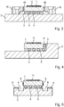
- FIG. 5 illustrated fifth embodiment differs from the first embodiment only in that several ways of implementing a flow stop for the material of the layer 5 are shown. Similar to the in FIG. 2 shown recess 7, a flow stop by a side of the measuring scale 1 and in the measuring direction X extending recess 8 in the carrier 3 may be provided. Alternatively or additionally, a flow stop may be formed by partial coating of material measure 1 and / or carrier 3 with a wetting-inhibiting material 9. The provision of a wetting-inhibiting coating is also called epilamization.
- the material measure 1 -as shown in the exemplary embodiments- can be rod-shaped.
- the measuring standard can also be band-shaped and the carrier 3 as a stable and rigid body.
- the carrier may be designed to be manageable together with the measuring tape in that the carrier is designed in the form of a profile, which is mounted for measuring the position of an object to be measured.
- the material measure can be held in a groove of this profile according to the invention and / or the profile can form a housing for the material measure.
- the material measure may be circular or it may be a band-shaped measuring graduation on an inner or outer surface of a drum, wherein the drum may form the carrier of the material measure.
- the measurement graduation may be designed for measurement in two dimensions, such measurement graduations also being called cross gratings or checkerboard grids.
- the material measure may also be a scanning of the position measuring device.
- the invention is not limited to the photoelectric scanning principle.
- the measuring graduation can also be designed to be magnetically, capacitively or inductively scanned.
Landscapes
- Physics & Mathematics (AREA)
- General Physics & Mathematics (AREA)
- Length Measuring Devices With Unspecified Measuring Means (AREA)
- Transmission And Conversion Of Sensor Element Output (AREA)
- A Measuring Device Byusing Mechanical Method (AREA)
Description
Die vorliegende Erfindung betrifft eine Anordnung mit einer an einem Träger befestigten Maßverkörperung nach dem Oberbegriff des Anspruchs 1.The present invention relates to an arrangement with a measuring embodiment attached to a carrier according to the preamble of
Zur Messung der Relativlage zweier Maschinenteile ist an einem der Maschinenteile eine Maßverkörperung zu befestigen und am anderen der zueinander beweglichen Maschinenteile eine Abtasteinheit. Bei der Positionsmessung wird eine Messteilung der Maßverkörperung von der Abtasteinheit abgetastet und positionsabhängige Abtastsignale generiert.To measure the relative position of two machine parts, a material measure is to be attached to one of the machine parts, and a scanning unit is attached to the other of the mutually movable machine parts. In the position measurement, a measurement graduation of the material measure is scanned by the scanning unit and position-dependent scanning signals are generated.
Die
Gemäß der
Aufgabe der Erfindung ist es, eine Anordnung mit einer an einem Träger befestigten Maßverkörperung anzugeben, wobei die Maßverkörperung möglichst driftfrei und temperaturstabil in seiner Lage gehalten wird, so dass eine reproduzierbare Positionsmessung ermöglicht wird.The object of the invention is to provide an arrangement with a measuring standard attached to a carrier, wherein the material measure is kept as drift-free and temperature-stable in its position, so that a reproducible position measurement is possible.
Gelöst wird diese Aufgabe durch die im Anspruch 1 angegebene Anordnung sowie mit der im Anspruch 11 angegebenen Positionsmesseinrichtung.This object is achieved by the arrangement specified in
Vorteilhafte Ausführungen der erfindungsgemäßen Anordnung sowie Positionsmesseinrichtung ergeben sich aus den Maßnahmen, die in den abhängigen Ansprüchen aufgeführt sind.Advantageous embodiments of the arrangement according to the invention and position measuring device result from the measures that are listed in the dependent claims.
Einzelheiten und Vorteile der vorliegenden Erfindung werden anhand der nachfolgenden Beschreibung von Ausführungsbeispielen in Verbindung mit den Figuren erläutert.Details and advantages of the present invention will be explained with reference to the following description of exemplary embodiments in conjunction with the figures.
Es zeigt
Figur 1- einen Längsschnitt einer erfindungsgemäß ausgebildeten Anordnung;
Figur 2- einen Längsschnitt eines zweiten Ausführungsbeispiels;
Figur 3- einen Querschnitt eines dritten Ausführungsbeispiels;
Figur 4- einen Querschnitt eines vierten Ausführungsbeispiels, und
Figur 5- einen Querschnitt eines fünften Ausführungsbeispiels.
- FIG. 1
- a longitudinal section of an inventive arrangement;
- FIG. 2
- a longitudinal section of a second embodiment;
- FIG. 3
- a cross section of a third embodiment;
- FIG. 4
- a cross section of a fourth embodiment, and
- FIG. 5
- a cross section of a fifth embodiment.
Anhand der
Die Messteilung 11 ist eine inkrementale Teilung, die bei der Positionsmessung in Messrichtungen X von der Abtasteinheit 2 zur Erzeugung von positionsabhängigen Abtastsignalen lichtelektrisch abgetastet wird. Die Messteilung 11 kann ein reflektierendes Amplitudengitter oder ein Phasengitter sein, das in bekannter Weise zur hochgenauen interferentiellen Positionsmessung dient.The
Die Maßverkörperung 1 ist an dem Träger 3 befestigt. Dieser Träger 3 besteht in der Regel aus einem Material dessen Ausdehnungskoeffizient vom Ausdehnungskoeffizient der Maßverkörperung 1 abweicht. Aus diesem Grund ist es erforderlich die Maßverkörperung 1 vom Träger 3 entkoppelt zu befestigen. Entkoppelt bedeutet dabei, dass sich Träger 3 und Maßverkörperung 1 unabhängig voneinander temperaturbedingt verlagern können ohne dass mechanische Spannungen vom Träger 3 auf die Maßverkörperung 1 übertragen werden, welche die Genauigkeit und Reproduzierbarkeit der Positionsmessung nachteilig beeinflussen. Die Lagerung der Maßverkörperung 1 am Träger 3 erfolgt somit schwimmend.The
Die Maßverkörperung 1 ist am Träger 3 mittels Abstandhalter 4 abgestützt. Diese Abstandhalter 4 sind auf der Oberfläche 31 des Trägers 3 zweidimensional räumlich verteilt angeordnet. Die Anordnung der Abstandhalter 4 ist derart, dass die Maßverkörperung 1 zumindest innerhalb eines Bereiches der Messteilung 11 unterstützt wird, welcher zur Positionsmessung von der Abtasteinheit 2 abtastbar ist. Die Unterstützung erfolgt also zumindest innerhalb eines Bereiches der Messteilung 11, der für die Positionsmessung genutzt wird.The
Die Abstandhalter 4 sind in eine Schicht 5 beweglich eingebettet und darin beweglich gebunden. Hierzu ist die Schicht 5 zwischen der Maßverkörperung 1 und dem Träger 3 derart angeordnet, dass diese die Maßverkörperung 1 am Träger 3 haftend hält. Aufgrund der Oberflächenspannung der Schicht 5 werden Maßverkörperung 1 und Träger 3 aneinander gezogen. Die Schicht 5 hat mehrere Funktionen. Sie verbindet die Maßverkörperung 1 und den Träger 3 haftend miteinander aufgrund von Adhäsionskräften der Schicht 5. Die Schicht 5 gleicht darüber hinaus unterschiedliche thermische Ausdehnungen zwischen dem Träger 3 und der Maßverkörperung 1 aus. Zusätzlich sorgt die Schicht 5 dafür, dass die Abstandhalter 4 im Spalt zwischen der Maßverkörperung 1 und dem Träger 3 gehalten werden, da die Abstandhalter 4 in die Schicht 5 eingebettet sind und das Schichtmaterial aufgrund der Kapillarwirkung im Spalt zwischen der Maßverkörperung 1 und dem Träger 3 gehalten wird. Die Schicht 5 bildet somit eine Art Käfig für die Abstandhalter 4, also den Kugelkäfig bei kugelförmigen Abstandhaltern 4. Weiterhin hat die Schicht 5 die Funktion als Gleitmittel für die Abstandhalter 4 zu wirken um die Reibung (Gleitreibung bzw. Rollreibung) zwischen den Abstandhaltern 4 und der Maßverkörperung 1 sowie zwischen den Abstandhaltern 4 und dem Träger 3 zu minimieren. Zusätzlich bewirken die Abstandhalter 4 eine exakte Einhaltung der Dicke D der Schicht 5 und somit die Möglichkeit einer definierten Einstellung der erforderlichen Haltekraft einerseits und der Begrenzung der erforderlichen Schubkraft andererseits um eine temperaturbedingte Verlagerung zwischen Maßverkörperung 1 und Träger 3 rückwirkungsfrei zu ermöglichen.The
Die Schicht 5 ist vorzugsweise ein viskoser Flüssigkeitsfilm, insbesondere ein Newtonsches Fluid hoher Viskosität, beispielsweise ein Ölfilm (z.B. Silikonöl) oder auch ein Bingham Fluid. Die Schicht 5 kann auch aus einer viskoelastischen Flüssigkeit, auch Gel genannt, gebildet sein.The
Typische Werte für die Dicke der Maßverkörperung 1 liegen bei 0,5mm bis 15mm. Die Dicke D der Schicht 5 und somit die Höhe der Abstandhalter 4 ist beispielsweise 1µm bis 500µm, typisch 50µm.Typical values for the thickness of the
Die Abstandhalter 4 bestehen aus einem Material, das auftretenden Druckkräften möglichst ohne Verformung standhält. Ein geeignetes Material ist insbesondere Glas, Glaskeramik, aber auch Keramik oder Metall.The
Vorteilhaft kann es sein, wenn die Abstandhalter 4 aus einem Material bestehen mit einer Dichte zumindest annähernd der Dichte des Materials der Schicht 5. Dies hat Vorteile bei der Einmischung der Abstandhalter 4 in die Schicht 5, da eine gleichmäßige Verteilung der Abstandhalter 4 im Material der Schicht 5 gewährleistet ist. Weiterhin ist gewährleistet, dass keine Entmischung zwischen den Abstandhaltern 4 und dem Material der Schicht 5 erfolgt, es ist nämlich gewährleistet, dass sich die Abstandhalter 4 bei allen Anbaulagen im Gleichgewicht in dem Material der Schicht 5 -also in dem Spalt der Dicke D- befindet.It may be advantageous if the
Als Abstandhalter 4 eignen sich besonders Kugeln oder Rollen. Der Durchmesser dieser Kugeln oder Rollen entspricht der Dicke D der Schicht 5. Somit kontaktieren die Kugeln bzw. die Rollen einerseits die Maßverkörperung 1 auf seiner Unterseite, also der Auflagefläche 12, jeweils punktförmig und andererseits den Träger 3 auf seiner Oberfläche 31 ebenfalls punktförmig. Die Kugeln bzw. Rollen sind rollbeweglich in die Schicht 5 eingebettet. Kugeln eignen sich als Abstandhalter 4 besonders, da diese in der Schicht 5 zweidimensional rollbeweglich gelagert sind.As
Das in der
Das in der
Das in der
Das in der
Für alle Ausführungsbeispiele gilt Folgendes.
Zur Längenmessung kann die Maßverkörperung 1 -wie in den Ausführungsbeispielen dargestellt- stabförmig ausgebildet sein. Die Maßverkörperung kann aber auch bandförmig ausgebildet sein und der Träger 3 als stabiler und biegesteifer Körper. Der Träger kann gemeinsam mit dem Maßband handhabbar ausgebildet sein, indem der Träger in Form eines Profils ausgebildet ist, welches zur Positionsmessung an ein zu messendes Objekt angebaut wird. Die Maßverkörperung kann in einer Nut dieses Profils erfindungsgemäß gehaltert sein und / oder das Profil kann ein Gehäuse für die Maßverkörperung bilden.The following applies to all exemplary embodiments.
For measuring the length, the material measure 1 -as shown in the exemplary embodiments-can be rod-shaped. The measuring standard can also be band-shaped and the
Zur Winkelmessung kann die Maßverkörperung kreisförmig ausgebildet sein oder es kann eine bandförmige Maßverkörperung an einer Innen- oder Außenfläche einer Trommel angeordnet sein, wobei die Trommel den Träger der Maßverkörperung bilden kann.For angle measurement, the material measure may be circular or it may be a band-shaped measuring graduation on an inner or outer surface of a drum, wherein the drum may form the carrier of the material measure.
Anstelle oder zusätzlich zu der inkrementalen Messteilung 11 kann auch eine absolute Codierung vorgesehen werden. Weiterhin kann die Messteilung zur Messung in zwei Dimensionen ausgebildet sein, wobei derartige Messteilungen auch Kreuzgitter oder Schachbrett-Gitter bezeichnet werden.Instead of or in addition to the
Die Maßverkörperung kann auch eine Abtastplatte der Positionsmesseinrichtung sein.The material measure may also be a scanning of the position measuring device.
Die Erfindung ist nicht auf das lichtelektrische Abtastprinzip beschränkt. Die Messteilung kann auch magnetisch, kapazitiv oder induktiv abtastbar ausgebildet sein.The invention is not limited to the photoelectric scanning principle. The measuring graduation can also be designed to be magnetically, capacitively or inductively scanned.
Claims (10)
- Assembly comprising a measurement scale (1) fixed to a support (3), the measurement scale (1) having a measuring graduation (11) and being supported on the support (3) via spacers (4) and fixed in a decoupled manner in such a way that different thermal expansions between the support (3) and the measurement scale (1) are compensated for, characterized in that
between the measurement scale (1) and the support (3) there is arranged a layer (5) which holds the measurement scale (1) in a manner adhering to the support (3), and in that the spacers (4) are embedded movably in this layer (5), the layer (5) being a viscous liquid or a visco-elastic liquid. - Assembly according to Claim 1, wherein the spacers (4) are distributed two-dimensionally and are arranged opposite the measuring graduation (11) that can be sensed by a sensing unit (2) for position measurement.
- Assembly according to one of the preceding claims, wherein the thickness (D) of the layer (5) is 1 µm to 500 µm.
- Assembly according to one of the preceding claims, wherein the spacers (4) consist of glass.
- Assembly according to one of the preceding Claims 1 to 3, wherein the spacers (4) consist of a material having a density at least approximately of the density of the material of the layer (5).
- Assembly according to one of the preceding claims, wherein the spacers (4) in the layer (5) are spheres or rollers that can move by rolling.
- Assembly according to Claim 6, wherein the diameter of the spheres or rollers is 1 µm to 500 µm.
- Assembly according to one of the preceding claims, wherein the measurement scale (1) is fixed to the support (3) in a fixed location at a position (P).
- Assembly according to one of the preceding claims, wherein a flow stop (7, 8, 9) for the material of the layer (5) is provided on the support (3) and/or on the measurement scale (1).
- Position measuring device comprising an arrangement according to one of the preceding claims and comprising a sensing unit (2) for sensing the measuring graduation (11) of the measurement scale (1).
Priority Applications (3)
| Application Number | Priority Date | Filing Date | Title |
|---|---|---|---|
| ES14193790.4T ES2615116T3 (en) | 2014-11-19 | 2014-11-19 | Arrangement with a measurement scale fixed on a support |
| EP14193790.4A EP3023742B1 (en) | 2014-11-19 | 2014-11-19 | Assembly comprising a measurement scale attached to a support |
| JP2015204479A JP6630113B2 (en) | 2014-11-19 | 2015-10-16 | Apparatus having a measurement standard fixed to a carrier |
Applications Claiming Priority (1)
| Application Number | Priority Date | Filing Date | Title |
|---|---|---|---|
| EP14193790.4A EP3023742B1 (en) | 2014-11-19 | 2014-11-19 | Assembly comprising a measurement scale attached to a support |
Publications (2)
| Publication Number | Publication Date |
|---|---|
| EP3023742A1 EP3023742A1 (en) | 2016-05-25 |
| EP3023742B1 true EP3023742B1 (en) | 2017-01-11 |
Family
ID=52020936
Family Applications (1)
| Application Number | Title | Priority Date | Filing Date |
|---|---|---|---|
| EP14193790.4A Active EP3023742B1 (en) | 2014-11-19 | 2014-11-19 | Assembly comprising a measurement scale attached to a support |
Country Status (3)
| Country | Link |
|---|---|
| EP (1) | EP3023742B1 (en) |
| JP (1) | JP6630113B2 (en) |
| ES (1) | ES2615116T3 (en) |
Cited By (1)
| Publication number | Priority date | Publication date | Assignee | Title |
|---|---|---|---|---|
| CN109708596A (en) * | 2017-10-26 | 2019-05-03 | 约翰内斯·海德汉博士有限公司 | Component with fixed yardstick at bracket |
Families Citing this family (1)
| Publication number | Priority date | Publication date | Assignee | Title |
|---|---|---|---|---|
| IT201900003817A1 (en) * | 2019-03-15 | 2020-09-15 | Parpas S P A | LINEAR ENCODER |
Family Cites Families (10)
| Publication number | Priority date | Publication date | Assignee | Title |
|---|---|---|---|---|
| DE3635511A1 (en) | 1986-10-18 | 1988-04-28 | Zeiss Carl Fa | BRACKET FOR MEASURING AND SHAPED EMBODIMENT |
| JPS63311738A (en) * | 1987-06-12 | 1988-12-20 | Omron Tateisi Electronics Co | Method of fixing sample |
| DE3929629A1 (en) | 1989-09-06 | 1991-03-07 | Zeiss Carl Fa | LENGTH OR ANGLE MEASURING DEVICE |
| JP2683148B2 (en) * | 1990-09-04 | 1997-11-26 | アルプス電気株式会社 | Transparent touch switch |
| DE10064734C2 (en) * | 2000-12-22 | 2003-07-31 | Heidenhain Gmbh Dr Johannes | Length measuring device |
| GB2411475B (en) * | 2004-02-24 | 2006-10-25 | Elliott Ind Ltd | Position detecting system |
| EP1783463B1 (en) * | 2005-11-04 | 2015-04-15 | Dr. Johannes Heidenhain GmbH | Method for fixing a scale to a support, thereto adapted scale and support with such a scale |
| DE102009002142A1 (en) * | 2009-04-02 | 2010-10-07 | Dr. Johannes Heidenhain Gmbh | An assembly with a scale attached to a support and method of holding a scale on a support |
| JP5471267B2 (en) * | 2009-10-07 | 2014-04-16 | トヨタ自動車株式会社 | Heterogeneous material composite |
| DE102009047120A1 (en) * | 2009-11-25 | 2011-05-26 | Dr. Johannes Heidenhain Gmbh | Arrangement with a scale attached to a support |
-
2014
- 2014-11-19 EP EP14193790.4A patent/EP3023742B1/en active Active
- 2014-11-19 ES ES14193790.4T patent/ES2615116T3/en active Active
-
2015
- 2015-10-16 JP JP2015204479A patent/JP6630113B2/en active Active
Non-Patent Citations (1)
| Title |
|---|
| None * |
Cited By (1)
| Publication number | Priority date | Publication date | Assignee | Title |
|---|---|---|---|---|
| CN109708596A (en) * | 2017-10-26 | 2019-05-03 | 约翰内斯·海德汉博士有限公司 | Component with fixed yardstick at bracket |
Also Published As
| Publication number | Publication date |
|---|---|
| JP6630113B2 (en) | 2020-01-15 |
| JP2016099341A (en) | 2016-05-30 |
| EP3023742A1 (en) | 2016-05-25 |
| ES2615116T3 (en) | 2017-06-05 |
Similar Documents
| Publication | Publication Date | Title |
|---|---|---|
| EP2697600B1 (en) | Apparatus and method for measuring the thickness of a measurement object | |
| EP0416391B1 (en) | Device for measuring angles or lengths | |
| EP3026389B1 (en) | Length measuring device | |
| EP0123895B1 (en) | Measuring apparatus | |
| EP0190270B1 (en) | Transducer for the electrical measurement of forces, torques, accelerations, pressures and mechanical stresses | |
| EP2037230A1 (en) | Length measuring device | |
| EP2018511B1 (en) | Machine for measuring or machining workpieces, especially coordinate measuring machine | |
| EP2302332A2 (en) | Length measuring device | |
| EP2348288B1 (en) | Assembly with a measuring rod attached to a holder | |
| DE19854318A1 (en) | Length measuring device | |
| EP3023742B1 (en) | Assembly comprising a measurement scale attached to a support | |
| EP3308106B1 (en) | Sensor and sensor element | |
| DE10153147A1 (en) | Method of applying a scale to a support | |
| EP0259471A1 (en) | Device for checking and/or acquiring the dimensions, changes in dimension, the positon and changes in position of workpieces, regulating elements and the similar. | |
| DE202016004348U1 (en) | Device for measuring structural changes via a variable path to e.g. building surfaces | |
| AT515951A1 (en) | positioning | |
| DE102009002142A1 (en) | An assembly with a scale attached to a support and method of holding a scale on a support | |
| DE10253178B4 (en) | Use a layer of diamond-like carbon | |
| DE102010012701B4 (en) | Micro-force sensor | |
| DE102012219417B4 (en) | Method for determining the expansion coefficient and the uniform temperature of a gauge block | |
| AT510009A4 (en) | MEASURING DEVICE AND METHOD FOR THICKNESS MEASUREMENT OF A TAPE | |
| EP1731877B1 (en) | Encoder of a measurement system | |
| WO2017085285A1 (en) | Measuring device comprising a thermal unit | |
| AT520955B1 (en) | Measuring device for measuring the distance between two selected points | |
| DE102009019764B3 (en) | Length measuring device for measuring dimensions of bodies, particularly inner- and outer diameters, used in mechanical drive- and transmission elements and in circular body, has carrier element, which is adapted to body to be measured |
Legal Events
| Date | Code | Title | Description |
|---|---|---|---|
| 17P | Request for examination filed |
Effective date: 20141119 |
|
| AK | Designated contracting states |
Kind code of ref document: A1 Designated state(s): AL AT BE BG CH CY CZ DE DK EE ES FI FR GB GR HR HU IE IS IT LI LT LU LV MC MK MT NL NO PL PT RO RS SE SI SK SM TR |
|
| AX | Request for extension of the european patent |
Extension state: BA ME |
|
| PUAI | Public reference made under article 153(3) epc to a published international application that has entered the european phase |
Free format text: ORIGINAL CODE: 0009012 |
|
| REG | Reference to a national code |
Ref country code: DE Ref legal event code: R079 Ref document number: 502014002474 Country of ref document: DE Free format text: PREVIOUS MAIN CLASS: G01D0003028000 Ipc: G01D0005244000 |
|
| RIC1 | Information provided on ipc code assigned before grant |
Ipc: G01B 5/00 20060101ALI20160630BHEP Ipc: G01D 5/244 20060101AFI20160630BHEP Ipc: G01D 5/347 20060101ALI20160630BHEP |
|
| GRAP | Despatch of communication of intention to grant a patent |
Free format text: ORIGINAL CODE: EPIDOSNIGR1 |
|
| INTG | Intention to grant announced |
Effective date: 20160805 |
|
| GRAS | Grant fee paid |
Free format text: ORIGINAL CODE: EPIDOSNIGR3 |
|
| GRAA | (expected) grant |
Free format text: ORIGINAL CODE: 0009210 |
|
| RBV | Designated contracting states (corrected) |
Designated state(s): AL AT BE BG CH CY CZ DE DK EE ES FI FR GB GR HR HU IE IS IT LI LT LU LV MC MK MT NL NO PL PT RO RS SE SI SK SM TR |
|
| AK | Designated contracting states |
Kind code of ref document: B1 Designated state(s): AL AT BE BG CH CY CZ DE DK EE ES FI FR GB GR HR HU IE IS IT LI LT LU LV MC MK MT NL NO PL PT RO RS SE SI SK SM TR |
|
| REG | Reference to a national code |
Ref country code: GB Ref legal event code: FG4D Free format text: NOT ENGLISH |
|
| REG | Reference to a national code |
Ref country code: CH Ref legal event code: EP |
|
| REG | Reference to a national code |
Ref country code: AT Ref legal event code: REF Ref document number: 861724 Country of ref document: AT Kind code of ref document: T Effective date: 20170115 |
|
| REG | Reference to a national code |
Ref country code: IE Ref legal event code: FG4D Free format text: LANGUAGE OF EP DOCUMENT: GERMAN |
|
| REG | Reference to a national code |
Ref country code: CH Ref legal event code: NV Representative=s name: ICB INGENIEURS CONSEILS EN BREVETS SA, CH |
|
| REG | Reference to a national code |
Ref country code: DE Ref legal event code: R096 Ref document number: 502014002474 Country of ref document: DE |
|
| REG | Reference to a national code |
Ref country code: LT Ref legal event code: MG4D |
|
| REG | Reference to a national code |
Ref country code: NL Ref legal event code: MP Effective date: 20170111 |
|
| REG | Reference to a national code |
Ref country code: ES Ref legal event code: FG2A Ref document number: 2615116 Country of ref document: ES Kind code of ref document: T3 Effective date: 20170605 |
|
| PG25 | Lapsed in a contracting state [announced via postgrant information from national office to epo] |
Ref country code: NL Free format text: LAPSE BECAUSE OF FAILURE TO SUBMIT A TRANSLATION OF THE DESCRIPTION OR TO PAY THE FEE WITHIN THE PRESCRIBED TIME-LIMIT Effective date: 20170111 |
|
| PG25 | Lapsed in a contracting state [announced via postgrant information from national office to epo] |
Ref country code: HR Free format text: LAPSE BECAUSE OF FAILURE TO SUBMIT A TRANSLATION OF THE DESCRIPTION OR TO PAY THE FEE WITHIN THE PRESCRIBED TIME-LIMIT Effective date: 20170111 Ref country code: IS Free format text: LAPSE BECAUSE OF FAILURE TO SUBMIT A TRANSLATION OF THE DESCRIPTION OR TO PAY THE FEE WITHIN THE PRESCRIBED TIME-LIMIT Effective date: 20170511 Ref country code: LT Free format text: LAPSE BECAUSE OF FAILURE TO SUBMIT A TRANSLATION OF THE DESCRIPTION OR TO PAY THE FEE WITHIN THE PRESCRIBED TIME-LIMIT Effective date: 20170111 Ref country code: GR Free format text: LAPSE BECAUSE OF FAILURE TO SUBMIT A TRANSLATION OF THE DESCRIPTION OR TO PAY THE FEE WITHIN THE PRESCRIBED TIME-LIMIT Effective date: 20170412 Ref country code: NO Free format text: LAPSE BECAUSE OF FAILURE TO SUBMIT A TRANSLATION OF THE DESCRIPTION OR TO PAY THE FEE WITHIN THE PRESCRIBED TIME-LIMIT Effective date: 20170411 Ref country code: FI Free format text: LAPSE BECAUSE OF FAILURE TO SUBMIT A TRANSLATION OF THE DESCRIPTION OR TO PAY THE FEE WITHIN THE PRESCRIBED TIME-LIMIT Effective date: 20170111 |
|
| PG25 | Lapsed in a contracting state [announced via postgrant information from national office to epo] |
Ref country code: RS Free format text: LAPSE BECAUSE OF FAILURE TO SUBMIT A TRANSLATION OF THE DESCRIPTION OR TO PAY THE FEE WITHIN THE PRESCRIBED TIME-LIMIT Effective date: 20170111 Ref country code: SE Free format text: LAPSE BECAUSE OF FAILURE TO SUBMIT A TRANSLATION OF THE DESCRIPTION OR TO PAY THE FEE WITHIN THE PRESCRIBED TIME-LIMIT Effective date: 20170111 Ref country code: BG Free format text: LAPSE BECAUSE OF FAILURE TO SUBMIT A TRANSLATION OF THE DESCRIPTION OR TO PAY THE FEE WITHIN THE PRESCRIBED TIME-LIMIT Effective date: 20170411 Ref country code: PL Free format text: LAPSE BECAUSE OF FAILURE TO SUBMIT A TRANSLATION OF THE DESCRIPTION OR TO PAY THE FEE WITHIN THE PRESCRIBED TIME-LIMIT Effective date: 20170111 Ref country code: LV Free format text: LAPSE BECAUSE OF FAILURE TO SUBMIT A TRANSLATION OF THE DESCRIPTION OR TO PAY THE FEE WITHIN THE PRESCRIBED TIME-LIMIT Effective date: 20170111 Ref country code: PT Free format text: LAPSE BECAUSE OF FAILURE TO SUBMIT A TRANSLATION OF THE DESCRIPTION OR TO PAY THE FEE WITHIN THE PRESCRIBED TIME-LIMIT Effective date: 20170511 |
|
| REG | Reference to a national code |
Ref country code: DE Ref legal event code: R097 Ref document number: 502014002474 Country of ref document: DE |
|
| PG25 | Lapsed in a contracting state [announced via postgrant information from national office to epo] |
Ref country code: EE Free format text: LAPSE BECAUSE OF FAILURE TO SUBMIT A TRANSLATION OF THE DESCRIPTION OR TO PAY THE FEE WITHIN THE PRESCRIBED TIME-LIMIT Effective date: 20170111 Ref country code: RO Free format text: LAPSE BECAUSE OF FAILURE TO SUBMIT A TRANSLATION OF THE DESCRIPTION OR TO PAY THE FEE WITHIN THE PRESCRIBED TIME-LIMIT Effective date: 20170111 Ref country code: SK Free format text: LAPSE BECAUSE OF FAILURE TO SUBMIT A TRANSLATION OF THE DESCRIPTION OR TO PAY THE FEE WITHIN THE PRESCRIBED TIME-LIMIT Effective date: 20170111 Ref country code: CZ Free format text: LAPSE BECAUSE OF FAILURE TO SUBMIT A TRANSLATION OF THE DESCRIPTION OR TO PAY THE FEE WITHIN THE PRESCRIBED TIME-LIMIT Effective date: 20170111 |
|
| PLBE | No opposition filed within time limit |
Free format text: ORIGINAL CODE: 0009261 |
|
| STAA | Information on the status of an ep patent application or granted ep patent |
Free format text: STATUS: NO OPPOSITION FILED WITHIN TIME LIMIT |
|
| PG25 | Lapsed in a contracting state [announced via postgrant information from national office to epo] |
Ref country code: SM Free format text: LAPSE BECAUSE OF FAILURE TO SUBMIT A TRANSLATION OF THE DESCRIPTION OR TO PAY THE FEE WITHIN THE PRESCRIBED TIME-LIMIT Effective date: 20170111 Ref country code: DK Free format text: LAPSE BECAUSE OF FAILURE TO SUBMIT A TRANSLATION OF THE DESCRIPTION OR TO PAY THE FEE WITHIN THE PRESCRIBED TIME-LIMIT Effective date: 20170111 |
|
| 26N | No opposition filed |
Effective date: 20171012 |
|
| PG25 | Lapsed in a contracting state [announced via postgrant information from national office to epo] |
Ref country code: SI Free format text: LAPSE BECAUSE OF FAILURE TO SUBMIT A TRANSLATION OF THE DESCRIPTION OR TO PAY THE FEE WITHIN THE PRESCRIBED TIME-LIMIT Effective date: 20170111 |
|
| PG25 | Lapsed in a contracting state [announced via postgrant information from national office to epo] |
Ref country code: MC Free format text: LAPSE BECAUSE OF FAILURE TO SUBMIT A TRANSLATION OF THE DESCRIPTION OR TO PAY THE FEE WITHIN THE PRESCRIBED TIME-LIMIT Effective date: 20170111 |
|
| PG25 | Lapsed in a contracting state [announced via postgrant information from national office to epo] |
Ref country code: LU Free format text: LAPSE BECAUSE OF NON-PAYMENT OF DUE FEES Effective date: 20171119 |
|
| REG | Reference to a national code |
Ref country code: FR Ref legal event code: ST Effective date: 20180731 Ref country code: BE Ref legal event code: MM Effective date: 20171130 |
|
| REG | Reference to a national code |
Ref country code: IE Ref legal event code: MM4A |
|
| PG25 | Lapsed in a contracting state [announced via postgrant information from national office to epo] |
Ref country code: MT Free format text: LAPSE BECAUSE OF FAILURE TO SUBMIT A TRANSLATION OF THE DESCRIPTION OR TO PAY THE FEE WITHIN THE PRESCRIBED TIME-LIMIT Effective date: 20170111 |
|
| PG25 | Lapsed in a contracting state [announced via postgrant information from national office to epo] |
Ref country code: FR Free format text: LAPSE BECAUSE OF NON-PAYMENT OF DUE FEES Effective date: 20171130 Ref country code: IE Free format text: LAPSE BECAUSE OF NON-PAYMENT OF DUE FEES Effective date: 20171119 |
|
| PG25 | Lapsed in a contracting state [announced via postgrant information from national office to epo] |
Ref country code: BE Free format text: LAPSE BECAUSE OF NON-PAYMENT OF DUE FEES Effective date: 20171130 |
|
| PG25 | Lapsed in a contracting state [announced via postgrant information from national office to epo] |
Ref country code: HU Free format text: LAPSE BECAUSE OF FAILURE TO SUBMIT A TRANSLATION OF THE DESCRIPTION OR TO PAY THE FEE WITHIN THE PRESCRIBED TIME-LIMIT; INVALID AB INITIO Effective date: 20141119 |
|
| PG25 | Lapsed in a contracting state [announced via postgrant information from national office to epo] |
Ref country code: CY Free format text: LAPSE BECAUSE OF FAILURE TO SUBMIT A TRANSLATION OF THE DESCRIPTION OR TO PAY THE FEE WITHIN THE PRESCRIBED TIME-LIMIT Effective date: 20170111 |
|
| PG25 | Lapsed in a contracting state [announced via postgrant information from national office to epo] |
Ref country code: MK Free format text: LAPSE BECAUSE OF FAILURE TO SUBMIT A TRANSLATION OF THE DESCRIPTION OR TO PAY THE FEE WITHIN THE PRESCRIBED TIME-LIMIT Effective date: 20170111 |
|
| PG25 | Lapsed in a contracting state [announced via postgrant information from national office to epo] |
Ref country code: TR Free format text: LAPSE BECAUSE OF FAILURE TO SUBMIT A TRANSLATION OF THE DESCRIPTION OR TO PAY THE FEE WITHIN THE PRESCRIBED TIME-LIMIT Effective date: 20170111 |
|
| PG25 | Lapsed in a contracting state [announced via postgrant information from national office to epo] |
Ref country code: AL Free format text: LAPSE BECAUSE OF FAILURE TO SUBMIT A TRANSLATION OF THE DESCRIPTION OR TO PAY THE FEE WITHIN THE PRESCRIBED TIME-LIMIT Effective date: 20170111 |
|
| REG | Reference to a national code |
Ref country code: AT Ref legal event code: MM01 Ref document number: 861724 Country of ref document: AT Kind code of ref document: T Effective date: 20191119 |
|
| PG25 | Lapsed in a contracting state [announced via postgrant information from national office to epo] |
Ref country code: AT Free format text: LAPSE BECAUSE OF NON-PAYMENT OF DUE FEES Effective date: 20191119 |
|
| PGFP | Annual fee paid to national office [announced via postgrant information from national office to epo] |
Ref country code: ES Payment date: 20230125 Year of fee payment: 9 |
|
| PGFP | Annual fee paid to national office [announced via postgrant information from national office to epo] |
Ref country code: GB Payment date: 20231123 Year of fee payment: 10 |
|
| PGFP | Annual fee paid to national office [announced via postgrant information from national office to epo] |
Ref country code: IT Payment date: 20231124 Year of fee payment: 10 Ref country code: DE Payment date: 20231121 Year of fee payment: 10 Ref country code: CH Payment date: 20231201 Year of fee payment: 10 |
|
| PGFP | Annual fee paid to national office [announced via postgrant information from national office to epo] |
Ref country code: ES Payment date: 20240129 Year of fee payment: 10 |