EP2018511B1 - Machine for measuring or machining workpieces, especially coordinate measuring machine - Google Patents
Machine for measuring or machining workpieces, especially coordinate measuring machine Download PDFInfo
- Publication number
- EP2018511B1 EP2018511B1 EP07724627.0A EP07724627A EP2018511B1 EP 2018511 B1 EP2018511 B1 EP 2018511B1 EP 07724627 A EP07724627 A EP 07724627A EP 2018511 B1 EP2018511 B1 EP 2018511B1
- Authority
- EP
- European Patent Office
- Prior art keywords
- cover plate
- machine according
- main body
- machine
- guide
- Prior art date
- Legal status (The legal status is an assumption and is not a legal conclusion. Google has not performed a legal analysis and makes no representation as to the accuracy of the status listed.)
- Expired - Fee Related
Links
Images


Classifications
-
- G—PHYSICS
- G01—MEASURING; TESTING
- G01B—MEASURING LENGTH, THICKNESS OR SIMILAR LINEAR DIMENSIONS; MEASURING ANGLES; MEASURING AREAS; MEASURING IRREGULARITIES OF SURFACES OR CONTOURS
- G01B5/00—Measuring arrangements characterised by the use of mechanical techniques
- G01B5/004—Measuring arrangements characterised by the use of mechanical techniques for measuring coordinates of points
- G01B5/008—Measuring arrangements characterised by the use of mechanical techniques for measuring coordinates of points using coordinate measuring machines
-
- G—PHYSICS
- G01—MEASURING; TESTING
- G01B—MEASURING LENGTH, THICKNESS OR SIMILAR LINEAR DIMENSIONS; MEASURING ANGLES; MEASURING AREAS; MEASURING IRREGULARITIES OF SURFACES OR CONTOURS
- G01B5/00—Measuring arrangements characterised by the use of mechanical techniques
- G01B5/0002—Arrangements for supporting, fixing or guiding the measuring instrument or the object to be measured
- G01B5/0009—Guiding surfaces; Arrangements compensating for non-linearity there-of
Definitions
- the present invention relates to a machine for measuring or processing workpieces, in particular a coordinate measuring machine, with a machine head which is movable relative to a workpiece holder, and with a machine frame, on which at least the machine head is arranged, wherein the machine frame comprises a guide body with at least one Guide surface for an air bearing and a counter-body which is supported on the guide surface via the air bearing, and wherein the guide body and the counter body along the guide surface are movable relative to each other.
- Such a machine is in the form of a coordinate measuring machine DE 34 41 488 A1 known.
- a coordinate measuring machine is a machine with a measuring head, which can be moved relative to a measuring object in a measuring volume.
- the measuring head is brought into a defined position relative to a measuring point on the measuring object.
- the measuring point is touched, for example, with a stylus arranged on the measuring head.
- spatial coordinates of the measuring point can be determined based on the known position of the measuring head in the measuring volume. If one determines the spatial coordinates of several defined measuring points on a measuring object, geometrical dimensions or even the spatial form of the measuring object can also be determined.
- a typical field of application for such coordinate measuring machines is the measurement of workpieces as part of a quality control.
- the present invention is preferably used in coordinate measuring machines, it can also be applied to machine tools and other machines in which a machine head is to be moved with high accuracy relative to a workpiece or the like.
- the measuring head is arranged on a machine frame in portal construction.
- the measuring head is located at the lower free end of a quill, which sits on the cross member of the portal and which can be moved relative to the portal in two spatial directions.
- the sleeve here consists of an aluminum tube with a rectangular cross section, wherein the outer sides of the tube represent the guide surfaces of the quill.
- the quill slides with their guide surfaces between air bearings, which are arranged on a cross slide, which in turn is movably mounted on the portal.
- guide bodies made of granite, steel, Al 2 O 3 ceramic or silicon carbide are used in known coordinate measuring machines. All these materials On the one hand offer a high rigidity, which is advantageous for the guidance accuracy of the machine frame.
- JP 2002-130269 a cross slide is known in which a guide body and a counter body, which are supported on air bearings to each other, are made of quartz glass.
- This known cross slide is intended for applications in the field of nanotechnology and biotechnology.
- the glass scales typically carry a scale that can be read using suitable sensors.
- the glass scales are attached to the guide body of a track axis or at least parallel to the guide body on the machine frame.
- DE 29 43 431 A1 a measuring machine in which a glass scale is arranged on the underside of a workpiece table.
- the glass scale itself has nothing to do with the mechanical guidance of the machine head and / or the workpiece holder
- DE 35 15 685 A1 discloses a coordinate measuring machine with a supported on a counter-body via air bearings guide body, the guide surface is chemically nickel-plated. Against this background, it is an object of the present invention to develop a machine of the type mentioned, so that the manufacturing costs are reduced at least approximately the same accuracy of the linear guides.
- the guide body includes a supporting body and a cover plate, which is arranged on the base body and forms the guide surface for the air bearing.
- the new machine thus has a guide body which is formed at least in two parts and has a base body and a cover plate (cover body) arranged thereon.
- the cover plate is thus a second body which forms the guide body together with the supporting base body.
- the guide body of the new machine is composed of at least two previously separated body parts.
- the body can be produced with much lower requirements, in particular with regard to the roughness and tightness of the surface.
- the cover plate which forms the guide surface for the air bearing, can be made largely independent of the carrying loads that must absorb the guide body as a whole. In particular, it is possible to use for the cover plate materials that would not be able to take the required load by itself.
- cover plate other materials may be used for the cover plate, such as special glasses or other materials that have a suitable tightness and roughness.
- the base body and the cover plate are made of different materials.
- the base body made of aluminum, granite, Al 2 O 3 ceramic, steel, silicon carbide or a combination thereof.
- the cover plate is made in preferred embodiments of the invention made of glass, in particular of float glass or window glass.
- the cover plate serves primarily to provide the necessary roughness and tightness for an air bearing guide. Due to its thermal conductivity, its weight and its flowability, glass is not optimal for the production of a guide body, for example suitable, at least when the movement strokes and loads are large. On the other hand, float glass is relatively cheap and it has a roughness and tightness that is well suited for the support of air bearings. Conversely, aluminum, for example, due to its thermal conductivity and its relatively low weight is very well suited for the production of load-bearing basic bodies. The use of different materials for the main body and the cover plate allows a substantial reduction in manufacturing costs without sacrificing the quality and guiding accuracy of the machine.
- the base body has a first thermal expansion coefficient
- the cover plate has a second coefficient of thermal expansion
- at least one intermediate element is arranged, which has a third coefficient of thermal expansion, wherein the third thermal expansion coefficient between the first and second coefficient of expansion is.
- the guide body has a multilayer structure with at least one intermediate element (intermediate layer) between the base body and the cover plate.
- This embodiment is particularly advantageous when two different materials are used with significantly different coefficients of expansion for the main body and the cover plate, which can lead to mechanical stresses and deformations.
- one or more intermediate elements are used in the form of foil strips, for example in the form of thin metal foils.
- the cover plate made of glass, in particular of float glass.
- the cover plate is largely congruent on the base body.
- the guide body is largely compatible with conventional guide bodies made of aluminum, granite or ceramic, since it has a substantially homogeneous guide surface, which covers the underlying body.
- this embodiment provides a maximum tread for supporting the air bearing in conjunction with small dimensions of the guide body.
- the cover plate is arranged at least partially movable on the base body.
- the cover plate is floating on an oil-like substance, in particular an adhesive oil, stored on the body.
- a relative mobility of the cover plate relative to the base body helps to avoid mechanical stresses within the guide body due to different thermal expansion coefficients.
- the different materials can expand and contract at least partially independently of each other in this embodiment of the invention.
- the dimensional accuracy of the guide body is improved with this configuration.
- cover plate and the base body are connected in places rigidly.
- this design ensures that the cover plate is held in a positionally accurate manner on the base body.
- this design allows only a few times rigid Link a local relative mobility, which is advantageous to avoid deformation due to different thermal expansions.
- the cover plate is fixed to the base body by means of elastic retaining elements.
- the elastic retaining elements are elastic adhesive pads, which are glued to both the base body and with the cover plate, but allow a relative mobility in the transverse direction.
- the elastic holding elements may be flexurally elastic clamps or snap elements, that is to say mechanical spring elements which assume a defined rest position on account of their material properties.
- the elastic retaining elements may include silicone joints or the like.
- these embodiments enable a stable and positionally accurate connection between the base body and the cover plate.
- they allow a relative mobility between the cover plate and the base body in order to avoid stresses due to different thermal expansions.
- the holding elements are arranged below the cover plate.
- This embodiment is advantageous because the top of the cover plate is completely available as a guide surface for supporting the air bearing.
- the new guide body of this embodiment can be realized the same shape and thus compatible with conventional guide bodies.
- the holding elements are arranged in at least one recess.
- the depressions are located at the top of the base body, on which the cover plate is placed.
- cover plate simplifies manufacture of the cover plate, especially if it is a glass cover plate.
- Suitable depressions can be realized cost-neutral, for example, in an extruded aluminum profile.
- the embodiments thus contribute to further reduce the manufacturing cost of the new machine.
- the arrangement of the holding elements in at least one recess has the advantage that the cover plate can otherwise rest flat on the base body, allowing a more stable connection and better support of the air bearings.
- the at least one recess is a groove which runs on the base body.
- This embodiment enables a particularly simple and cost-effective implementation.
- the air bearing is offset from the wells supported on the guide surface.
- the air bearing does not run above the wells over the guide surface, but with a lateral offset, so to speak so sloping next to the depressions. This allows a particularly stable and dimensionally stable support of the air bearing on the guide surface.
- the base body has at least a first and a second longitudinal side, on which at least a first and a second cover plate are arranged.
- This embodiment is particularly advantageous when the guide body is held between a plurality of opposing air bearings.
- the embodiment is particularly well suited, for example, for the sleeve of a coordinate measuring machine in gantry design. By realizing the guide body on opposite sides with separate cover plates, the manufacturing cost of the machine can be further reduced.
- first and the second cover plate are elastically connected to each other.
- the cover plates surround the base body and keep each other in position due to their mutual connection.
- four cover plates are arranged on the four outer longitudinal sides of a base body with a square cross-section and the four cover plates are glued together at their adjacent edges with a permanently elastic adhesive.
- This embodiment enables a particularly cost-effective realization of a guide body which is held in two mutually perpendicular spatial directions with air bearings.
- this embodiment allows a particularly cost-effective implementation of the quill of a coordinate measuring machine (more generally: a machine) in gantry design.
- FIG. 1 a coordinate measuring machine according to an embodiment of the present invention is designated in its entirety by the reference numeral 10.
- the coordinate measuring machine 10 has a base 12 on which a portal 14 is arranged.
- the portal 14 may be moved in a longitudinal direction, commonly referred to as a y-axis.
- a carriage 16 is arranged, which is movable in the transverse direction.
- the direction of movement of the carriage 16 is commonly referred to as the x-axis.
- a quill 18 is mounted, which can be moved in a third spatial direction.
- the third spatial direction is usually referred to as the z-axis.
- the current axis position of the portal 14, the carriage 16 and the sleeve 18 can be determined by means of scales 20, 22, 24, which are arranged along the axes of movement.
- Embodiments are glass scales, as used in conventional machines.
- measurement scales 20, 22, 24 are arranged directly on a cover plate which serves as a guide surface according to the present invention (to be explained below).
- a probe 26 At the lower free end of the sleeve 18 is a probe 26 with a stylus 28 (not shown here masstabsgetreu) arranged.
- the stylus 28 carries at its free end a Tastkugel, which serves to touch a measuring point on a measuring object 30. From the position of the probe 26 in space then space coordinates of the probed measuring point can be determined.
- the reference numeral 32 denotes an evaluation and control unit, on the one hand controls the drives (not shown here) in the three axes of motion and on the other hand determines the spatial coordinates of a probed measuring point. As in FIG. 1 As shown, the control unit 32 may be connected to a control panel 34 for selectively enabling automatic and / or manual control of the probe 26.
- At least the sleeve 18 has a guide body which is formed in the manner described below.
- FIG. 2 A first embodiment of the guide body of the sleeve 18 is in FIG. 2 shown.
- the guide body is designated in its entirety by the reference numeral 40. It has a base body 42 with a square profile.
- the base body is made of aluminum, and it is a hollow profile, as in FIG. 2 is shown with the opening 44.
- cover plate 46 On the four outer longitudinal sides of the base body 42, a cover plate 46 is arranged in each case.
- the four cover plates are designated by the reference numerals 46a, 46b, 46c and 46d.
- the cover plates 46a-46d are made of float glass. However, it may also be coated or uncoated special glasses or cover plates made of another material, such as metal or ceramic.
- the cover plates 46a-46d form with their outer upper side 48 each a guide surface on which one or more air bearings 50, 52 are supported in a conventional manner.
- the air bearings 50, 52 are each connected to a counter body, which in FIG. 2 only schematically shown at reference numeral 54.
- the counter-body 54 In the coordinate measuring machine according to FIG. 1 the counter-body 54 is a part of the carriage 16, in which the quill 18 is mounted.
- the direction in which the quill can be moved relative to the counter body 54 is in FIG FIG. 2 indicated by a double arrow 56.
- the cover plates 46 are glued to a local splice 58 with the underlying longitudinal side of the body 42.
- the local splice 58 is located at one end of the base body 42.
- the rigid fixation of the cover plate 46 on the base body 42 is limited to the local splice 58 here.
- the remaining area of the cover plate 46 is floatingly mounted on the base 42, on an adhesive oil 60.
- a similar way of attaching a glass body on a base is used, for example, to attach a glass scale 20, 22, 24 to a conventional guide body.
- the adhesive oil 60 the glass plate 46 is also held away from the local splice 58 on the base body 42, but it can expand in the longitudinal direction largely forcibly.
- the local splice 58 is arranged here at the front end of the base body 42. However, it can also be arranged at another location of the main body 42 (centrally or at the other end, several local splices), and it may be point or line-shaped.
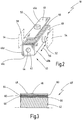
- FIG. 3 shows a further embodiment of a guide body 40 'according to the invention.
- Like reference numerals designate the same elements as before.
- the intermediate element 64 is a steel foil having a thermal expansion coefficient of about 12.0 ⁇ m / mK.
- the intermediate element 66 is here a brass foil with a thermal expansion coefficient of about 18.5 ⁇ m / mK.
- the base body 42 is made of aluminum with a thermal expansion coefficient of about 23.8 microns / mK and the cover plate 46 is made of glass with a coefficient of thermal expansion of about 7.7 microns / mK.
- the individual layers are connected to each other with an adhesive or adhesive oil 60. Due to the multilayer construction with different material layers, a step-like transition between the high expansion coefficient of aluminum and the relatively small expansion coefficient of glass is achieved. Stresses due to temperature-induced expansion are degraded in layers. At the same time, this embodiment offers a high partial compressive stiffness, which is advantageous for supporting the air bearings 50, 52.
- FIG. 4 shows an embodiment with a main body 42 ', in the outer longitudinal sides grooves 70 extend.
- the grooves 70 serve to receive adhesive plug 72, as shown in FIG. 5 is shown in cross section.
- the adhesive plugs 72 are glued both at the bottom of the cover plates 46 and at the bottom of the grooves 70.
- it is a permanently elastic adhesive.
- the grooves 70 have a clear inner diameter d, which is significantly larger than the corresponding outer diameter of the adhesive plug 72, so that in each case a gap 74 remains laterally of the adhesive plug 72. Due to the gaps 74, the adhesive plug 72 can move laterally in the grooves 70 and the cover plates 46 can follow this lateral movement despite the fixation on the main body 42 '. Accordingly, the cover plates 46 are largely tension-free attached to the base body 42 despite different thermal expansion coefficients.
- each cover plate 46 can move both longitudinally and transversely with respect to the main body 42.
- a plurality of local splices 58 may be provided over the length of the main body 42 '.
- the base body 42 has only one longitudinal groove 70 on each longitudinal side which runs approximately centrally to the longitudinal side, thus covering the cover plate 46 directly and to the left of the groove 70 directly on the corresponding longitudinal side of the base body 42", advantageously again an adhesive oil (not shown) between the underside of the cover plate 46 and the main body 42 "Here it is preferred if the air bearings are not centrally supported on the guide surface 48, but laterally (to the right and / or to the left) offset to the The air bearings 50, 52 are thus supported in areas of the guide surface 48, which is indicated at reference numeral 76. As in FIG. 6 is shown, in this embodiment, in each case at least two air bearings are used on each guide surface 48.
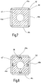
- FIG. 7 shows an embodiment in which a base 42 similar to that of FIG. 2 is used.
- the cover plates 46a are 46d at their outer edges 80 connected to each other, as shown at reference numeral 82.
- the connection is made using a permanently elastic adhesive 82.
- the cover plates 46a-46d are in turn mounted on the base body 42 via an adhesive oil 60 (not shown here).
- a local splice 58, as in FIG. 2 can also be used. It can in the embodiment according to FIG. 7 but also omitted.
- the cover plates are held by their mutual elastic connection on the base body 42.
- FIG. 8 shows a further embodiment for fastening the cover plates 46a - 46d to a base 42 ', which in turn has longitudinal grooves 70' here.
- the longitudinal grooves 70 ' here are conical or otherwise formed with an undercut.
- On the back of each cover plate 46a - 46d one or more spring elements 86 are fixed, for example glued.
- the spring elements 86 engage in the grooves 70 'and hold the cover plates 46a-46d due to their spring force in the grooves 70'. Since the spring elements 46 are flexible and, moreover, can move in the longitudinal grooves 70 ', the cover plates 46a-46d are fastened to the base body 42 largely free of tension.
- an adhesive oil 60 (not shown) or the like may be provided between the underside of the cover plates 46a-46d and the base body 42 '.
- the scale needed for the scale 24 may be applied directly to one of the cover plates 46a-46d.
- other guide bodies of the coordinate measuring machine 10 may be formed in the manner according to the invention.
- a cover plate 46 can be fastened to a base body 42 with the aid of external clips, brackets or the like, the clips or brackets then engaging around the cover plate 46 in the edge region.
- the fixing of the cover plate to the base body is at most in places rigid, so that the cover plate can move at least partially relative to the base body.
- cover plates are completely corrosion-free, other materials, including processed metals, can also be used for the cover plates.
Description
Die vorliegende Erfindung betrifft eine Maschine zum Vermessen oder Bearbeiten von Werkstücken, insbesondere ein Koordinatenmessgerät, mit einem Maschinenkopf, der relativ zu einer Werkstückaufnahme verfahrbar ist, und mit einem Maschinengestell, an dem zumindest der Maschinenkopf angeordnet ist, wobei das Maschinengestell einen Führungskörper mit zumindest einer Führungsfläche für ein Luftlager sowie einen Gegenkörper aufweist, der an der Führungsfläche über das Luftlager abgestützt ist, und wobei der Führungskörper und der Gegenkörper entlang der Führungsfläche relativ zueinander verfahrbar sind.The present invention relates to a machine for measuring or processing workpieces, in particular a coordinate measuring machine, with a machine head which is movable relative to a workpiece holder, and with a machine frame, on which at least the machine head is arranged, wherein the machine frame comprises a guide body with at least one Guide surface for an air bearing and a counter-body which is supported on the guide surface via the air bearing, and wherein the guide body and the counter body along the guide surface are movable relative to each other.
Eine solche Maschine ist in Form eines Koordinatenmessgerätes aus
Ein Koordinatenmessgerät ist eine Maschine mit einem Messkopf, der relativ zu einem Messobjekt in einem Messvolumen verfahren werden kann. Der Messkopf wird in eine definierte Position relativ zu einem Messpunkt an dem Messobjekt gebracht. Bei taktilen Koordinatenmessgeräten wird der Messpunkt beispielsweise mit einem am Messkopf angeordneten Taststift angetastet. Anschließend lassen sich Raumkoordinaten des Messpunktes anhand der bekannten Stellung des Messkopfes im Messvolumen bestimmen. Wenn man an einem Messobjekt die Raumkoordinaten von mehreren definierten Messpunkten bestimmt, lassen sich außerdem geometrische Abmessungen oder sogar die Raumform des Messobjektes bestimmen. Ein typisches Einsatzgebiet für solche Koordinatenmessgeräte ist die Vermessung von Werkstücken im Rahmen einer Qualitätskontrolle.A coordinate measuring machine is a machine with a measuring head, which can be moved relative to a measuring object in a measuring volume. The measuring head is brought into a defined position relative to a measuring point on the measuring object. In the case of tactile coordinate measuring machines, the measuring point is touched, for example, with a stylus arranged on the measuring head. Subsequently, spatial coordinates of the measuring point can be determined based on the known position of the measuring head in the measuring volume. If one determines the spatial coordinates of several defined measuring points on a measuring object, geometrical dimensions or even the spatial form of the measuring object can also be determined. A typical field of application for such coordinate measuring machines is the measurement of workpieces as part of a quality control.
Wenngleich die vorliegende Erfindung bevorzugt bei Koordinatenmessgeräten zum Einsatz kommt, kann sie auch bei Werkzeugmaschinen und anderen Maschinen verwendet werden, bei denen ein Maschinenkopf mit hoher Genauigkeit relativ zu einem Werkstück oder dergleichen bewegt werden soll.Although the present invention is preferably used in coordinate measuring machines, it can also be applied to machine tools and other machines in which a machine head is to be moved with high accuracy relative to a workpiece or the like.
Bei dem bekannten Koordinatenmessgerät ist der Messkopf an einem Maschinengestell in Portalbauweise angeordnet. Der Messkopf befindet sich am unteren freien Ende einer Pinole, die am Querträger des Portals sitzt und die relativ zu dem Portal in zwei Raumrichtungen verfahren werden kann. Die Pinole besteht hier aus einem Aluminiumrohr mit rechteckigem Querschnitt, wobei die Außenseiten des Rohrs die Führungsflächen der Pinole darstellen. Die Pinole gleitet mit ihren Führungsflächen zwischen Luftlagern, die an einem Querschlitten angeordnet sind, der wiederum an dem Portal beweglich gelagert ist. Die Verwendung eines Aluminiumrohrs als Führungskörper, der die Führungsflächen für die Luftlager bildet, hat sich bei Koordinatenmessgeräten als eine zweckmäßige Realisierung erwiesen, weil Aluminium eine gute Wärmeleitfähigkeit besitzt, so dass thermisch verursachte Deformationen gering sind.In the known coordinate measuring machine, the measuring head is arranged on a machine frame in portal construction. The measuring head is located at the lower free end of a quill, which sits on the cross member of the portal and which can be moved relative to the portal in two spatial directions. The sleeve here consists of an aluminum tube with a rectangular cross section, wherein the outer sides of the tube represent the guide surfaces of the quill. The quill slides with their guide surfaces between air bearings, which are arranged on a cross slide, which in turn is movably mounted on the portal. The use of an aluminum tube as a guide body, which forms the guide surfaces for the air bearings, has proved in coordinate measuring machines as a convenient implementation, because aluminum has a good thermal conductivity, so that thermally induced deformations are low.
Alternativ werden bei bekannten Koordinatenmessgeräten auch Führungskörper aus Granit, Stahl, Al2O3-Keramik oder Siliziumkarbid verwendet. All diese Materialien bieten einerseits eine hohe Steifigkeit, was für die Führungsgenauigkeit des Maschinengestells von Vorteil ist. Nachteilig ist andererseits, dass die Oberflächen der Materialien sehr aufwändig bearbeitet werden müssen, da Führungsflächen für Luftlager hohe Anforderungen an die Ebenheit, Rautiefe und Dichtheit der Oberfläche stellen. Dies hat zur Folge, dass die Herstellung einer luftlagergerechten Oberfläche bis zu 2/3 der Herstellungskosten eines geeigneten Führungskörpers ausmacht. Aus einem Buch mit dem Titel "Koordinatenmesstechnik im industriellen Einsatz" von Hans Joachim Neumann, erschienen im Verlag Moderne Industrie, ist es bekannt, das bei Koordinatenmessgeräten der oberen Geräteklasse Führungskörper verwendet werden, die aus einem hart beschichteten Aluminium bestehen. Diese Technologie wird von der Anmelderin der vorliegenden Erfindung unter der Bezeichnung "Carat" vermarktet. Auch die Herstellung solcher Führungskörper ist jedoch aufwändig und teuer.Alternatively, guide bodies made of granite, steel, Al 2 O 3 ceramic or silicon carbide are used in known coordinate measuring machines. All these materials On the one hand offer a high rigidity, which is advantageous for the guidance accuracy of the machine frame. A disadvantage, on the other hand, that the surfaces of the materials must be processed very expensive, since guide surfaces for air bearings make high demands on the flatness, roughness and tightness of the surface. This has the consequence that the production of an air-bearing surface up to 2/3 of the production costs of a suitable guide body makes. From a book titled "Coordinate metrology in industrial use" by Hans Joachim Neumann, published by Verlag Moderne Industrie, it is known that coordinate measuring devices of the upper device class use guide bodies consisting of a hard-coated aluminum. This technology is marketed by the assignee of the present invention under the name "Carat". However, the production of such guide body is complex and expensive.
Aus
Darüber hinaus ist es bei gattungsgemäßen Maschinen seit langem bekannt, Maßstäbe aus Glas zu verwenden, um eine aktuelle Verfahrposition des Messkopfes und/oder der Werkstückaufnahme zu bestimmen. Die Glasmaßstäbe tragen typischerweise eine Skala, die mit Hilfe von geeigneten Sensoren abgelesen werden kann. Typischerweise sind die Glasmaßstäbe an dem Führungskörper einer Verfahrachse oder zumindest parallel zu dem Führungskörper an dem Maschinengestell befestigt. Beispielsweise offenbart
Diese Aufgabe wird gemäß einem Aspekt der vorliegenden Erfindung durch eine Maschine der eingangs genannten Art gelöst, bei der der Führungskörper einen tragenden Grundkörper und eine Deckplatte beinhaltet, die auf dem Grundkörper angeordnet ist und die Führungsfläche für das Luftlager bildet.This object is achieved according to one aspect of the present invention by a machine of the type mentioned, in which the guide body includes a supporting body and a cover plate, which is arranged on the base body and forms the guide surface for the air bearing.
Die neue Maschine besitzt somit einen Führungskörper, der zumindest zweiteilig ausgebildet ist und einen Grundkörper und eine darauf angeordnete Deckplatte (Deckkörper) besitzt. Im Gegensatz zu einer Beschichtung handelt es sich bei der Deckplatte also um einen zweiten Körper, der zusammen mit dem tragenden Grundkörper den Führungskörper bildet. Mit anderen Worten ist der Führungskörper der neuen Maschine aus zumindest zwei zuvor getrennten Körperteilen zusammengesetzt.The new machine thus has a guide body which is formed at least in two parts and has a base body and a cover plate (cover body) arranged thereon. In contrast to a coating, the cover plate is thus a second body which forms the guide body together with the supporting base body. In other words, the guide body of the new machine is composed of at least two previously separated body parts.
Dadurch, dass man eine separate Deckplatte auf einem tragenden Grundkörper befestigt, kann der Grundkörper mit wesentlich geringeren Anforderungen, insbesondere im Hinblick auf die Rauhigkeit und Dichtheit der Oberfläche, hergestellt werden. Andererseits kann die Deckplatte, die die Führungsfläche für das Luftlager bildet, weitgehend unabhängig von den Traglasten hergestellt werden, die der Führungskörper insgesamt aufnehmen muss. Insbesondere ist es möglich, für die Deckplatte Materialien zu verwenden, die für sich genommen nicht in der Lage wären, die erforderliche Traglast aufzunehmen.The fact that one attaches a separate cover plate on a supporting body, the body can be produced with much lower requirements, in particular with regard to the roughness and tightness of the surface. On the other hand, the cover plate, which forms the guide surface for the air bearing, can be made largely independent of the carrying loads that must absorb the guide body as a whole. In particular, it is possible to use for the cover plate materials that would not be able to take the required load by itself.
Darüber hinaus ist es aufgrund des zweiteiligen Aufbaus möglich, Führungsflächen für Luftlager in großer Stückzahl bzw. in großen Abmessungen herzustellen und erst anschließend auf die individuellen Abmessungen einer Maschine zurechtzuschneiden. Allein schon hierdurch lassen sich die Herstellungskosten der neuen Maschine reduzieren. Zusätzlich bietet die Flexibilität, die sich aufgrund des möglichen Materialmixes ergibt, ein Kostenreduzierungspotential. In einem besonders bevorzugten Ausführungsbeispiel wird herkömmliches Floatglas als Deckplatte verwendet, da sich gezeigt hat, dass die Rauhigkeit und Dichtheit von Floatglas für eine Abstützung von Luftlagern gut geeignet ist. Die Herstellungskosten für die Deckplatte sind damit wesentlich geringer als beispielsweise die Bearbeitung eines Aluminiumgrundkörpers, der eine vergleichbare Rauhigkeit und Dichtheit bieten soll.In addition, due to the two-part construction, it is possible to produce guide surfaces for air bearings in large numbers or in large dimensions and then to cut them to the individual dimensions of a machine. This alone can reduce the manufacturing costs of the new machine. In addition, the flexibility offered by the possible material mix gives a cost reduction potential. In a particularly preferred embodiment, conventional float glass is used as a cover plate, since it has been shown that the roughness and tightness of float glass for a support of air bearings is well suited. The cost of the cover plate are thus much lower than, for example, the processing of an aluminum body, which should provide a comparable roughness and tightness.
In anderen Ausführungsbeispielen können jedoch auch andere Materialien für die Deckplatte verwendet werden, beispielsweise spezielle Gläser oder auch andere Werkstoffe, die eine geeignete Dichtheit und Rauheit aufweisen.However, in other embodiments, other materials may be used for the cover plate, such as special glasses or other materials that have a suitable tightness and roughness.
Insgesamt lässt sich durch eine geeignete Kombination eines tragenden Grundkörpers mit einem luftlagertauglichen glatten Deckmaterial ein Führungskörper herstellen, der im Vergleich zu bislang bekannten Führungskörpern deutlich billiger ist. Infolgedessen sind auch die Herstellungskosten für die Maschine insgesamt reduziert. Die oben genannte Aufgabe ist daher vollständig gelöst.Overall, can be produced by a suitable combination of a supporting body with an air bearing suitable smooth cover material, a guide body, which is much cheaper compared to previously known guide bodies. As a result, the manufacturing cost of the machine as a whole is reduced. The above object is therefore completely solved.
In einer bevorzugten Ausgestaltung der Erfindung sind der Grundkörper und die Deckplatte aus verschiedenen Materialien hergestellt. Beispielsweise besteht der Grundkörper aus Aluminium, Granit, Al2O3-Keramik, Stahl, Siliziumkarbid oder einer Kombination davon. Demgegenüber ist die Deckplatte in bevorzugten Ausgestaltungen der Erfindung aus Glas hergestellt, insbesondere aus Floatglas bzw. Fensterglas.In a preferred embodiment of the invention, the base body and the cover plate are made of different materials. For example, the base body made of aluminum, granite, Al 2 O 3 ceramic, steel, silicon carbide or a combination thereof. In contrast, the cover plate is made in preferred embodiments of the invention made of glass, in particular of float glass or window glass.
Die Verwendung unterschiedlicher Materialien für den Grundkörper und die Deckplatte ermöglicht es, die Materialien entsprechend den unterschiedlichen Aufgabenstellungen zu einem optimalen Kosten-Nutzen-Verhältnis auszuwählen. Während es bei dem Grundkörper vorrangig darauf ankommt, eine möglichst gerade, tragfähige und langzeitstabile Struktur zu finden, dient die Deckplatte vorrangig dazu, die für eine Luftlagerführung erforderliche Rauheit und Dichtheit bereitzustellen. Glas ist beispielsweise aufgrund seiner thermischen Leitfähigkeit, aufgrund seines Gewichts und seiner Fließfähigkeit nicht optimal für die Herstellung eines Führungskörpers geeignet, zumindest wenn die Bewegungshübe und Traglasten groß sind. Andererseits ist Floatglas relativ günstig und es besitzt eine Rauheit und Dichtheit, die für die Abstützung von Luftlagern gut geeignet ist. Umgekehrt eignet sich beispielsweise Aluminium aufgrund seiner thermischen Leitfähigkeit und seines relativ geringen Gewichts sehr gut für die Herstellung von tragenden Grundkörpern. Die Verwendung von unterschiedlichen Materialien für den Grundkörper und die Deckplatte ermöglicht eine wesentliche Reduzierung der Herstellungskosten ohne Einbußen in Bezug auf die Qualität und Führungsgenauigkeit der Maschine.The use of different materials for the base body and the cover plate makes it possible to select the materials according to the different tasks at an optimal cost-benefit ratio. While it is important in the main body to find the most straight, sustainable and long-term stable structure, the cover plate serves primarily to provide the necessary roughness and tightness for an air bearing guide. Due to its thermal conductivity, its weight and its flowability, glass is not optimal for the production of a guide body, for example suitable, at least when the movement strokes and loads are large. On the other hand, float glass is relatively cheap and it has a roughness and tightness that is well suited for the support of air bearings. Conversely, aluminum, for example, due to its thermal conductivity and its relatively low weight is very well suited for the production of load-bearing basic bodies. The use of different materials for the main body and the cover plate allows a substantial reduction in manufacturing costs without sacrificing the quality and guiding accuracy of the machine.
In einer weiteren Ausgestaltung besitzt der Grundkörper einen ersten thermischen Ausdehnungskoeffizienten, die Deckplatte besitzt einen zweiten thermischen Ausdehnungskoeffizienten, und zwischen der Deckplatte und dem Grundkörper ist zumindest ein Zwischenelement angeordnet, das einen dritten thermischen Ausdehnungskoeffizienten besitzt, wobei der dritte thermische Ausdehnungskoeffizient größenmäßig zwischen dem ersten und zweiten Ausdehnungskoeffizienten liegt.In a further embodiment, the base body has a first thermal expansion coefficient, the cover plate has a second coefficient of thermal expansion, and between the cover plate and the base body at least one intermediate element is arranged, which has a third coefficient of thermal expansion, wherein the third thermal expansion coefficient between the first and second coefficient of expansion is.
In dieser Ausgestaltung besitzt der Führungskörper einen mehrlagigen Aufbau mit zumindest einem Zwischenelement (Zwischenlage) zwischen dem Grundkörper und der Deckplatte. Diese Ausgestaltung ist besonders vorteilhaft, wenn zwei unterschiedliche Materialien mit deutlich voneinander abweichenden Ausdehnungskoeffizienten für den Grundkörper und die Deckplatte verwendet werden, was zu mechanischen Spannungen und Deformationen führen kann. Die Verwendung eines Zwischenelements mit einem Ausdehnungskoeffizienten, der betragsmäßig zwischen den Ausdehnungskoeffizienten der Deckplatte und des Grundkörpers liegt, ermöglicht einen stufenweisen bzw. schichtweisen Abbau der temperaturbedingten Spannungen. Thermisch bedingte Deformationen lassen sich dadurch reduzieren. Besonders vorteilhaft ist es, wenn ein oder mehrere Zwischenelemente in Form von Folienbändern verwendet werden, beispielsweise in Form von dünnen Metallfolien.In this embodiment, the guide body has a multilayer structure with at least one intermediate element (intermediate layer) between the base body and the cover plate. This embodiment is particularly advantageous when two different materials are used with significantly different coefficients of expansion for the main body and the cover plate, which can lead to mechanical stresses and deformations. The use of an intermediate element with an expansion coefficient which lies in the amount between the expansion coefficients of the cover plate and the base body, allows a gradual degradation of the temperature-induced stresses. Thermally induced deformations can be reduced thereby. It is particularly advantageous if one or more intermediate elements are used in the form of foil strips, for example in the form of thin metal foils.
In einer weiteren Ausgestaltung besteht die Deckplatte aus Glas, insbesondere aus Floatglas.In a further embodiment, the cover plate made of glass, in particular of float glass.
Die Vorteile dieser Ausgestaltung, nämlich die günstigen Materialkosten und die gute Eignung des Materials für die Führungsfläche eines Luftlagers, wurden bereits oben ausführlich erläutert.The advantages of this embodiment, namely the favorable material costs and the good suitability of the material for the guide surface of an air bearing, have already been explained in detail above.
In einer weiteren Ausgestaltung liegt die Deckplatte weitgehend kongruent auf dem Grundkörper auf.In a further embodiment, the cover plate is largely congruent on the base body.
In dieser Ausgestaltung ist der Führungskörper weitgehend kompatibel zu herkömmlichen Führungskörpern aus Aluminium, Granit oder Keramik, da er eine weitgehend homogene Führungsfläche aufweist, die den darunter liegenden Grundkörper verdeckt. Außerdem bietet diese Ausgestaltung eine maximale Lauffläche zum Abstützen des Luftlagers in Verbindung mit geringen Abmessungen des Führungskörpers.In this embodiment, the guide body is largely compatible with conventional guide bodies made of aluminum, granite or ceramic, since it has a substantially homogeneous guide surface, which covers the underlying body. In addition, this embodiment provides a maximum tread for supporting the air bearing in conjunction with small dimensions of the guide body.
In einer weiteren Ausgestaltung ist die Deckplatte zumindest teilweise beweglich auf dem Grundkörper angeordnet. In einer besonders bevorzugten Ausgestaltung ist die Deckplatte schwimmend auf einer ölartigen Substanz, insbesondere einem Haftöl, auf dem Grundkörper gelagert.In a further embodiment, the cover plate is arranged at least partially movable on the base body. In a particularly preferred embodiment, the cover plate is floating on an oil-like substance, in particular an adhesive oil, stored on the body.
Eine relative Beweglichkeit der Deckplatte gegenüber dem Grundkörper trägt dazu bei, mechanische Spannungen innerhalb des Führungskörpers aufgrund von unterschiedlichen thermischen Ausdehnungskoeffizienten zu vermeiden. Die unterschiedlichen Materialien können sich in dieser Ausgestaltung der Erfindung zumindest teilweise unabhängig voneinander ausdehnen und zusammenziehen. Die Maßhaltigkeit des Führungskörpers wird mit dieser Ausgestaltung verbessert.A relative mobility of the cover plate relative to the base body helps to avoid mechanical stresses within the guide body due to different thermal expansion coefficients. The different materials can expand and contract at least partially independently of each other in this embodiment of the invention. The dimensional accuracy of the guide body is improved with this configuration.
In einer weiteren Ausgestaltung sind die Deckplatte und der Grundkörper stellenweise starr miteinander verbunden.In a further embodiment, the cover plate and the base body are connected in places rigidly.
Diese Ausgestaltung sorgt einerseits dafür, dass die Deckplatte positionsgenau auf dem Grundkörper gehalten wird. Andererseits ermöglicht eine nur stellenweise starre Verbindung eine lokale relative Beweglichkeit, was vorteilhaft ist, um Deformationen aufgrund unterschiedlicher thermischer Ausdehnungen zu vermeiden.On the one hand, this design ensures that the cover plate is held in a positionally accurate manner on the base body. On the other hand, allows only a few times rigid Link a local relative mobility, which is advantageous to avoid deformation due to different thermal expansions.
In einer weiteren Ausgestaltung ist die Deckplatte an dem Grundkörper mit Hilfe von elastischen Halteelementen fixiert. In besonders bevorzugten Ausgestaltungen sind die elastischen Halteelemente elastische Klebepfropfen, die sowohl mit dem Grundkörper als auch mit der Deckplatte verklebt sind, jedoch eine relative Beweglichkeit in Querrichtung ermöglichen. Alternativ hierzu können die elastischen Halteelemente in anderen Ausgestaltungen biegeelastische Klammern oder Schnappelemente sein, also mechanische Federelemente, die aufgrund ihrer Materialeigenschaften eine definierte Ruhelage einnehmen. In weiteren Ausgestaltungen können die elastischen Halteelemente Silikonfugen oder dergleichen beinhalten.In a further embodiment, the cover plate is fixed to the base body by means of elastic retaining elements. In particularly preferred embodiments, the elastic retaining elements are elastic adhesive pads, which are glued to both the base body and with the cover plate, but allow a relative mobility in the transverse direction. Alternatively, in other embodiments, the elastic holding elements may be flexurally elastic clamps or snap elements, that is to say mechanical spring elements which assume a defined rest position on account of their material properties. In further embodiments, the elastic retaining elements may include silicone joints or the like.
Diese Ausgestaltungen ermöglichen einerseits eine stabile und positionsgenaue Verbindung zwischen Grundkörper und Deckplatte. Andererseits ermöglichen sie eine relative Beweglichkeit zwischen Deckplatte und Grundkörper, um Spannungen aufgrund von unterschiedlichen thermischen Ausdehnungen zu vermeiden.On the one hand, these embodiments enable a stable and positionally accurate connection between the base body and the cover plate. On the other hand, they allow a relative mobility between the cover plate and the base body in order to avoid stresses due to different thermal expansions.
In einer weiteren Ausgestaltung sind die Halteelemente unterhalb der Deckplatte angeordnet.In a further embodiment, the holding elements are arranged below the cover plate.
Diese Ausgestaltung ist von Vorteil, weil die Oberseite der Deckplatte vollständig als Führungsfläche zum Abstützen des Luftlagers zur Verfügung steht. Außerdem kann der neue Führungskörper dieser Ausgestaltung formgleich und somit kompatibel zu herkömmlichen Führungskörpern realisiert werden.This embodiment is advantageous because the top of the cover plate is completely available as a guide surface for supporting the air bearing. In addition, the new guide body of this embodiment can be realized the same shape and thus compatible with conventional guide bodies.
In einer weiteren Ausgestaltung sind die Halteelemente in zumindest einer Vertiefung angeordnet. Vorzugsweise befinden sich die Vertiefungen an der Oberseite des Grundkörpers, auf den die Deckplatte aufgelegt wird.In a further embodiment, the holding elements are arranged in at least one recess. Preferably, the depressions are located at the top of the base body, on which the cover plate is placed.
Diese Ausgestaltungen vereinfachen die Herstellung der Deckplatte, insbesondere wenn es sich um eine Deckplatte aus Glas handelt. Geeignete Vertiefungen können beispielsweise in einem Aluminiumstranggussprofil kostenneutral realisiert werden. Die Ausgestaltungen tragen somit dazu bei, die Herstellungskosten der neuen Maschine weiter zu senken. Darüber hinaus besitzt die Anordnung der Halteelemente in zumindest einer Vertiefung den Vorteil, dass die Deckplatte im Übrigen plan auf dem Grundkörper aufliegen kann, was eine stabilere Verbindung und eine bessere Abstützung der Luftlager ermöglicht.These embodiments simplify the manufacture of the cover plate, especially if it is a glass cover plate. Suitable depressions can be realized cost-neutral, for example, in an extruded aluminum profile. The embodiments thus contribute to further reduce the manufacturing cost of the new machine. In addition, the arrangement of the holding elements in at least one recess has the advantage that the cover plate can otherwise rest flat on the base body, allowing a more stable connection and better support of the air bearings.
In einer weiteren Ausgestaltung weist die zumindest eine Vertiefung parallel zu der Deckplatte einen Innendurchmesser auf, der wesentlich größer ist als ein entsprechender Außendurchmesser der Halteelemente.In a further embodiment, the at least one recess parallel to the cover plate on an inner diameter which is substantially larger than a corresponding outer diameter of the holding elements.
In dieser Ausgestaltung ist also ein Zwischenraum zwischen den Halteelementen und den seitlichen Innenwänden der Vertiefung. Aufgrund dieses Zwischenraums können sich die Halteelemente parallel zu der Deckplatte in der Vertiefung bewegen, wodurch mechanische Spannungen zwischen den beiden Körperteilen des Führungskörpers wirkungsvoll reduziert werden.In this embodiment, therefore, there is a gap between the holding elements and the lateral inner walls of the recess. Due to this gap, the holding elements can move parallel to the cover plate in the recess, whereby mechanical stresses between the two body parts of the guide body can be effectively reduced.
In einer weiteren Ausgestaltung ist die zumindest eine Vertiefung eine Nut, die an dem Grundkörper verläuft.In a further embodiment, the at least one recess is a groove which runs on the base body.
Diese Ausgestaltung ermöglicht eine besonders einfache und kostengünstige Realisierung.This embodiment enables a particularly simple and cost-effective implementation.
In einer weiteren Ausgestaltung ist das Luftlager versetzt zu den Vertiefungen an der Führungsfläche abgestützt.In a further embodiment, the air bearing is offset from the wells supported on the guide surface.
In dieser Ausgestaltung läuft das Luftlager nicht oberhalb der Vertiefungen über die Führungsfläche, sondern mit einem seitlichen Versatz dazu, gewissermaßen also schräge neben den Vertiefungen. Dadurch wird eine besonders stabile und maßhaltige Abstützung der Luftlager auf der Führungsfläche ermöglicht.In this embodiment, the air bearing does not run above the wells over the guide surface, but with a lateral offset, so to speak so sloping next to the depressions. This allows a particularly stable and dimensionally stable support of the air bearing on the guide surface.
In einer weiteren Ausgestaltung weist der Grundkörper zumindest eine erste und eine zweite Längsseite auf, auf denen zumindest eine erste und eine zweite Deckplatte angeordnet sind.In a further embodiment, the base body has at least a first and a second longitudinal side, on which at least a first and a second cover plate are arranged.
Diese Ausgestaltung ist besonders vorteilhaft, wenn der Führungskörper zwischen mehreren, einander gegenüberliegenden Luftlagern gehalten wird. Die Ausgestaltung eignet sich beispielsweise besonders gut für die Pinole eines Koordinatenmessgerätes in Portalbauweise. Indem man den Führungskörper auf gegenüberliegenden Seiten mit separaten Deckplatten realisiert, lassen sich die Herstellungskosten der Maschine noch weiter reduzieren.This embodiment is particularly advantageous when the guide body is held between a plurality of opposing air bearings. The embodiment is particularly well suited, for example, for the sleeve of a coordinate measuring machine in gantry design. By realizing the guide body on opposite sides with separate cover plates, the manufacturing cost of the machine can be further reduced.
In einer weiteren Ausgestaltung sind die erste und die zweite Deckplatte elastisch miteinander verbunden. In einer besonders bevorzugten Ausgestaltung umgeben die Deckplatten den Grundkörper und halten sich aufgrund ihrer gegenseitigen Verbindung gegenseitig in Position. In einer besonders bevorzugten Variante dieser Ausgestaltung sind vier Deckplatten an den vier äußeren Längsseiten eines Grundkörpers mit quadratischem Querschnitt angeordnet und die vier Deckplatten sind an ihren benachbarten Kanten mit einem dauerelastischen Klebstoff miteinander verklebt.In a further embodiment, the first and the second cover plate are elastically connected to each other. In a particularly preferred embodiment, the cover plates surround the base body and keep each other in position due to their mutual connection. In a particularly preferred variant of this embodiment, four cover plates are arranged on the four outer longitudinal sides of a base body with a square cross-section and the four cover plates are glued together at their adjacent edges with a permanently elastic adhesive.
Diese Ausgestaltung ermöglicht eine besonders kostengünstige Realisierung eines Führungskörpers, der in zwei zueinander senkrechten Raumrichtungen mit Luftlagern gehalten wird. Insbesondere ermöglicht diese Ausgestaltung eine besonders kostengünstige Realisierung der Pinole eines Koordinatenmessgerätes (allgemeiner: einer Maschine) in Portalbauweise.This embodiment enables a particularly cost-effective realization of a guide body which is held in two mutually perpendicular spatial directions with air bearings. In particular, this embodiment allows a particularly cost-effective implementation of the quill of a coordinate measuring machine (more generally: a machine) in gantry design.
Es versteht sich, dass die vorstehend genannten und die nachstehend noch zu erläuternden Merkmale nicht nur in der jeweils angegebenen Kombination, sondern auch in anderen Kombinationen oder in Alleinstellung verwendbar sind, ohne den Rahmen der vorliegenden Erfindung zu verlassen.It is understood that the features mentioned above and those yet to be explained not only in the combination specified, but can also be used in other combinations or in isolation, without departing from the scope of the present invention.
Ausführungsbeispiele der Erfindung sind in der Zeichnung dargestellt und werden in der nachfolgenden Beschreibung näher erläutert. Es zeigen:
- Figur 1
- eine vereinfachte, schematische Darstellung eines Koordinatenmessgerätes in Portalbauweise, bei dem die Pinole in der erfindungsgemäßen Weise realisiert ist,
- Figur 2
- eine vereinfachte Darstellung eines ersten Ausführungsbeispiels für den Führungskörper des Koordinatenmessgerätes aus
Figur 1 , - Figur 3
- eine Querschnittsansicht, die einen mehrschichtigen Aufbau des Führungskörpers gemäß einem weiteren Ausführungsbeispiel der Erfindung zeigt,
- Figur 4
- ein weiteres Ausführungsbeispiel für einen Führungskörper nach der vorliegenden Erfindung,
- Figur 5
- das Ausführungsbeispiel aus
Figur 4 in weiteren Details, - Figur 6
- ein weiteres Ausführungsbeispiel für einen Führungskörper nach der vorliegenden Erfindung,
- Figur 7
- ein weiteres Ausführungsbeispiel für einen Führungskörper nach der vorliegenden Erfindung, und
- Figur 8
- ein weiteres Ausführungsbeispiel für einen Führungskörper nach der vorliegenden Erfindung.
- FIG. 1
- a simplified, schematic representation of a coordinate measuring machine in gantry design, in which the quill is realized in the manner according to the invention,
- FIG. 2
- a simplified representation of a first embodiment of the guide body of the coordinate measuring machine
FIG. 1 . - FIG. 3
- FIG. 3 is a cross-sectional view showing a multilayer structure of the guide body according to another embodiment of the invention; FIG.
- FIG. 4
- a further embodiment of a guide body according to the present invention,
- FIG. 5
- the embodiment
FIG. 4 in further details, - FIG. 6
- a further embodiment of a guide body according to the present invention,
- FIG. 7
- a further embodiment of a guide body according to the present invention, and
- FIG. 8
- a further embodiment of a guide body according to the present invention.
In
Das Koordinatenmessgerät 10 besitzt eine Basis 12, auf der ein Portal 14 angeordnet ist. Das Portal 14 kann in einer Längsrichtung, die üblicherweise als y-Achse bezeichnet wird, verfahren werden. Am oberen Querbalken des Portals 14 ist ein Schlitten 16 angeordnet, der in Querrichtung verfahrbar ist. Die Bewegungsrichtung des Schlittens 16 wird üblicherweise als x-Achse bezeichnet. Am Schlitten 16 ist eine Pinole 18 gelagert, die in einer dritten Raumrichtung verfahren werden kann. Die dritte Raumrichtung wird üblicherweise als z-Achse bezeichnet.The coordinate measuring
Die aktuelle Achsposition des Portals 14, des Schlittens 16 und der Pinole 18 lässt sich mit Hilfe von Maßstäben 20, 22, 24 bestimmen, die entlang der Bewegungsachsen angeordnet sind. In Ausführungsbeispielen handelt es sich um Glasmaßstäbe, wie sie auch bei herkömmlichen Maschinen verwendet werden. In einem anderen bevorzugten Ausführungsbeispiel sind Messskalen 20, 22, 24 direkt auf einer Deckplatte angeordnet, die nach der vorliegenden Erfindung als Führungsfläche dient (wird weiter unten erläutert).The current axis position of the portal 14, the
Am unteren freien Ende der Pinole 18 ist ein Tastkopf 26 mit einem Taststift 28 (hier nicht maßtabsgetreu dargestellt) angeordnet. Der Taststift 28 trägt an seinem freien Ende eine Tastkugel, die dazu dient, einen Messpunkt an einem Messobjekt 30 anzutasten. Aus der Stellung des Tastkopfes 26 im Raum lassen sich dann Raumkoordinaten des angetasteten Messpunktes bestimmen.At the lower free end of the
Mit der Bezugsziffer 32 ist eine Auswerte- und Steuereinheit bezeichnet, die einerseits die Antriebe (hier nicht näher dargestellt) in den drei Bewegungsachsen steuert und andererseits die Raumkoordinaten eines angetasteten Messpunktes bestimmt. Wie in
In einem bevorzugten Ausführungsbeispiel der Erfindung besitzt zumindest die Pinole 18 einen Führungskörper, der in der nachfolgend beschriebenen Weise ausgebildet ist.In a preferred embodiment of the invention, at least the
Ein erstes Ausführungsbeispiel für den Führungskörper der Pinole 18 ist in
Auf den vier äußeren Längsseiten des Grundkörpers 42 ist jeweils eine Deckplatte 46 angeordnet. In
In dem Ausführungsbeispiel der
Die lokale Klebestelle 58 ist hier am vorderen Ende des Grundkörpers 42 angeordnet. Sie kann jedoch auch an anderer Stelle des Grundkörpers 42 angeordnet sein (mittig oder am anderen Ende, mehrere lokale Klebestellen), und sie kann punkt- oder linienförmig ausgebildet sein.The
Hier sind zwischen der Deckplatte 46 und dem Grundkörper 42 zwei Zwischenelemente 64, 66 angeordnet. Das Zwischenelement 64 ist eine Stahlfolie mit einem thermischen Ausdehnungskoeffizienten von etwa 12,0 µm/mK. Das Zwischenelement 66 ist hier eine Messingfolie mit einem thermischen Ausdehnungskoeffizienten von etwa 18,5 µm/mK. Der Grundkörper 42 besteht aus Aluminium mit einem thermischen Ausdehnungskoeffizienten von etwa 23,8 µm/mK und die Deckplatte 46 besteht aus Glas mit einem thermischen Ausdehnungskoeffizienten von etwa 7,7 µm/mK. Die einzelnen Lagen sind mit einem Klebstoff oder Haftöl 60 miteinander verbunden. Durch den mehrlagigen Aufbau mit unterschiedlichen Materialschichten wird ein stufenartiger Übergang zwischen dem hohen Ausdehnungskoeffizienten von Aluminium und dem relativ kleinen Ausdehnungskoeffizienten von Glas erreicht. Spannungen aufgrund temperaturbedingter Ausdehnungen werden schichtweise abgebaut. Gleichzeitig bietet dieses Ausführungsbeispiel eine hohe partielle Drucksteifigkeit, was zum Abstützen der Luftlager 50, 52 von Vorteil ist.Here, between the
Besonders vorteilhaft ist es, wenn die Klebepfropfen 72 nicht über die gesamte Länge der Nuten 70 vorhanden sind, sondern nur lokale Klebestellen bilden. In diesem Fall kann sich jede Deckplatte 46 sowohl in Längsrichtung als auch in Querrichtung gegenüber dem Grundkörper 42 bewegen. Aus Stabilitätsgründen können auch mehrere lokale Klebestellen 58 über die Länge des Grundkörpers 42' vorgesehen sein.It is particularly advantageous if the adhesive plugs 72 are not present over the entire length of the
In einem weiteren Ausführungsbeispiel gemäß
Im Ausführungsbeispiel gemäß
In weiteren bevorzugten Ausführungsbeispielen der Erfindung kann die Skalierung, die für den Maßstab 24 benötigt wird, direkt auf einer der Deckplatten 46a - 46d aufgebracht sein. Des Weiteren können auch andere Führungskörper des Koordinatenmessgerätes 10 in der erfindungsgemäßen Weise ausgebildet sein.In other preferred embodiments of the invention, the scale needed for the
Schließlich kann alternativ zu einer lokalen Klebestelle 58, wie sie in
In weiteren Ausführungsbeispielen (hier nicht dargestellt) kann eine Deckplatte 46 mit Hilfe von äußeren Klammern, Bügeln oder dergleichen an einem Grundkörper 42 befestigt werden, wobei die Klammern oder Bügel die Deckplatte 46 dann im Kantenbereich umgreifen. Generell ist es in allen Fällen bevorzugt, wenn die Fixierung der Deckplatte an dem Grundkörper allenfalls stellenweise starr ist, so dass sich die Deckplatte zumindest bereichsweise gegenüber dem Grundkörper bewegen kann.In further exemplary embodiments (not shown here), a
Was das Material der Deckplatte angeht, bieten sich sämtliche Gläser an, deren Ebenheit im Bereich 1 µm oder kleiner liegt. Die Rautiefe sollte etwa Ra = 0,8 oder besser betragen. Wenngleich die Verwendung von Glas als Material für die Deckplatten den Vorteil besitzt, dass die Deckplatten vollständig korrosionsfrei sind, können auch andere Materialien einschließlich bearbeiteter Metalle für die Deckplatten verwendet werden.As far as the material of the cover plate is concerned, all glasses are available whose flatness is in the range of 1 μm or less. The roughness should be about Ra = 0.8 or better. Although the use of glass as the material for the cover plates has the advantage that the cover plates are completely corrosion-free, other materials, including processed metals, can also be used for the cover plates.
Claims (14)
- Machine for measuring or machining workpieces (30), in particular a coordinate measuring apparatus, having a machine head (26) which is displaceable relative to a workpiece receptacle (12), and having a machine frame (14, 16, 18) on which at least the machine head (26) is disposed, wherein the machine frame (14, 16, 18) has at least one guide body (40) having at least one guide face (48) for an air bearing (50, 52) and a counter body (54) which is supported on the guide face (48) by way of the air bearing (50, 52), and wherein the guide body (40) and the counter body (54) are displaceable relative to one another along the guide face (48), wherein the guide body (40) includes a supporting main body (42) and a cover plate (46) which is disposed on the main body (42) and forms the guide face (48) for the air bearing (50, 52), characterized in that the cover plate (46) is of glass, in particular float glass.
- Machine according to Claim 1, characterized in that the main body (42) and the cover plate (46) are made from dissimilar materials.
- Machine according to Claim 1 or 2, characterized in that the main body (42) has a first coefficient of thermal expansion, in that the cover plate (46) has a second coefficient of thermal expansion, and in that at least one intermediate element (64, 66) which has a third coefficient of thermal expansion is disposed between the cover plate (46) and the main body (42), wherein the third coefficient of thermal expansion in terms of value is between the first and the second coefficient of thermal expansion.
- Machine according to one of Claims 1 to 3, characterized in that the cover plate (46) bears on the main body (42) in a largely congruent manner.
- Machine according to one of Claims 1 to 4, characterized in that the cover plate (46) is disposed so as to be at least partially movable on the main body (42).
- Machine according to one of Claims 1 to 5, characterized in that the cover plate (46) and the main body (42) at points are rigidly interconnected.
- Machine according to one of Claims 1 to 6, characterized in that the cover plate (46) is fixed to the main body (42) with the aid of elastic holding elements (72; 86).
- Machine according to Claim 7, characterized in that the holding elements (72; 86) are disposed below the cover plate (46).
- Machine according to Claim 8, characterized in that the holding elements (72; 86) are disposed in at least one depression (70).
- Machine according to Claim 9, characterized in that the at least one depression (70), in a manner parallel with the cover plate (46), has an internal diameter (d) which is substantially larger than a respective external diameter of the holding elements (72).
- Machine according to Claim 9 or 10, characterized in that the at least one depression (70) is a groove which runs on the main body (42).
- Machine according to one of Claims 9 to 11, characterized in that the air bearing (76) is supported on the guide face (48) so as to be offset in relation to the depressions (70).
- Machine according to one of Claims 1 to 12, characterized in that the main body (42) has at least one first and one second longitudinal side, on which at least one first and one second cover plate (46a-d) are disposed,
- Machine according to Claim 13, characterized in that the first and the second cover plate (46a-d) are interconnected in an elastic manner.
Applications Claiming Priority (2)
| Application Number | Priority Date | Filing Date | Title |
|---|---|---|---|
| DE102006022501A DE102006022501A1 (en) | 2006-05-08 | 2006-05-08 | Machine for measuring or processing workpieces, in particular coordinate measuring machine |
| PCT/EP2007/003697 WO2007128431A2 (en) | 2006-05-08 | 2007-04-26 | Machine for measuring or machining workpieces, especially coordinate measuring machine |
Publications (2)
| Publication Number | Publication Date |
|---|---|
| EP2018511A2 EP2018511A2 (en) | 2009-01-28 |
| EP2018511B1 true EP2018511B1 (en) | 2017-06-28 |
Family
ID=38566985
Family Applications (1)
| Application Number | Title | Priority Date | Filing Date |
|---|---|---|---|
| EP07724627.0A Expired - Fee Related EP2018511B1 (en) | 2006-05-08 | 2007-04-26 | Machine for measuring or machining workpieces, especially coordinate measuring machine |
Country Status (3)
| Country | Link |
|---|---|
| EP (1) | EP2018511B1 (en) |
| DE (1) | DE102006022501A1 (en) |
| WO (1) | WO2007128431A2 (en) |
Families Citing this family (10)
| Publication number | Priority date | Publication date | Assignee | Title |
|---|---|---|---|---|
| DE102008046070A1 (en) * | 2008-09-05 | 2010-03-11 | Klaus Unger | Apparatus for the abrasive machining of large workpieces |
| WO2012099586A1 (en) * | 2011-01-20 | 2012-07-26 | Carl Zeiss Industrial Metrology, Llc | Modular ceramic guideway member |
| US10401144B2 (en) | 2011-12-06 | 2019-09-03 | Hexagon Technology Center Gmbh | Coordinate measuring machine having a camera |
| EP2610577B1 (en) * | 2011-12-30 | 2018-01-24 | Hexagon Metrology S.p.A. | Process for producing a beam element of a co-ordinate measuring machine, and measuring machine provided with said beam element |
| WO2013110337A1 (en) | 2012-01-26 | 2013-08-01 | Carl Zeiss Industrielle Messtechnik Gmbh | Machine having an improved preloaded fluid bearing |
| WO2018193227A1 (en) | 2017-04-19 | 2018-10-25 | Renishaw Plc | Bearing arrangement |
| EP3393023A1 (en) | 2017-04-19 | 2018-10-24 | Renishaw PLC | Linear motor mounts |
| EP3392610B1 (en) | 2017-04-19 | 2022-02-23 | Renishaw PLC | Bearing mount |
| CN110537073B (en) | 2017-04-19 | 2022-07-08 | 瑞尼斯豪公司 | Positioning device |
| EP3392611B1 (en) | 2017-04-19 | 2019-12-25 | Renishaw PLC | Contamination trap |
Citations (1)
| Publication number | Priority date | Publication date | Assignee | Title |
|---|---|---|---|---|
| DE3515685A1 (en) * | 1985-05-02 | 1986-11-06 | Mauser-Werke Oberndorf Gmbh, 7238 Oberndorf | Sleeve for a coordinate measuring machine |
Family Cites Families (13)
| Publication number | Priority date | Publication date | Assignee | Title |
|---|---|---|---|---|
| JPS5777905A (en) * | 1980-10-31 | 1982-05-15 | Mitsutoyo Mfg Co Ltd | Measurement of three-dimensional measuring machine |
| JPH02278009A (en) * | 1989-04-20 | 1990-11-14 | Ntn Corp | Static pressure gas bearing |
| DE3936463A1 (en) * | 1989-11-02 | 1991-05-08 | Zeiss Carl Fa | COORDINATE MEASURING DEVICE |
| US5036236A (en) * | 1990-05-07 | 1991-07-30 | Hughes Aircraft Company | Air gap matching proximity sensor for magnetic bearings |
| JPH04145219A (en) * | 1990-10-05 | 1992-05-19 | Nec Corp | Air bearing type guide |
| GB9207259D0 (en) * | 1992-04-02 | 1992-05-13 | Renishaw Metrology Ltd | Workpiece measuring machine |
| DE19510998C2 (en) * | 1995-03-25 | 1998-09-03 | Heidenhain Gmbh Dr Johannes | Position measuring device |
| EP0877224B1 (en) * | 1997-05-07 | 2004-01-07 | Mitutoyo Corporation | Method and instrument with probe for measuring inner or outer dimension of an object |
| US6238092B1 (en) * | 1999-06-01 | 2001-05-29 | Tru-Stone Corporation | Air bearing for a motion system |
| DE10159442B4 (en) * | 2000-12-22 | 2006-11-02 | Schott Ag | Calibration body for a coordinate measuring machine |
| DE10120553A1 (en) * | 2001-04-26 | 2002-10-31 | Werth Messtechnik Gmbh | Storage for a coordinate measuring machine in particular |
| US6837114B2 (en) * | 2003-03-21 | 2005-01-04 | Carmar Technology Co., Ltd. | Three-dimensional measure device with air bearings |
| US6829838B1 (en) * | 2003-09-09 | 2004-12-14 | Hexagon Metrology Ab | Temperature compensation system for a coordinate measuring machine |
-
2006
- 2006-05-08 DE DE102006022501A patent/DE102006022501A1/en not_active Withdrawn
-
2007
- 2007-04-26 WO PCT/EP2007/003697 patent/WO2007128431A2/en active Application Filing
- 2007-04-26 EP EP07724627.0A patent/EP2018511B1/en not_active Expired - Fee Related
Patent Citations (1)
| Publication number | Priority date | Publication date | Assignee | Title |
|---|---|---|---|---|
| DE3515685A1 (en) * | 1985-05-02 | 1986-11-06 | Mauser-Werke Oberndorf Gmbh, 7238 Oberndorf | Sleeve for a coordinate measuring machine |
Also Published As
| Publication number | Publication date |
|---|---|
| WO2007128431A3 (en) | 2008-08-21 |
| WO2007128431A2 (en) | 2007-11-15 |
| EP2018511A2 (en) | 2009-01-28 |
| DE102006022501A1 (en) | 2007-11-15 |
Similar Documents
| Publication | Publication Date | Title |
|---|---|---|
| EP2018511B1 (en) | Machine for measuring or machining workpieces, especially coordinate measuring machine | |
| EP2697600B1 (en) | Apparatus and method for measuring the thickness of a measurement object | |
| EP0372302B1 (en) | Coordinates measuring machine with one or more aluminium guiding elements | |
| EP2247915B1 (en) | Xy table with a measuring arrangement for position determination | |
| DE19859360C2 (en) | Machine tool with piezoelectric position correction device | |
| CH679334A5 (en) | ||
| DE102016201922B4 (en) | Linear guide, in particular for a coordinate measuring machine | |
| EP2302332B1 (en) | Length measuring device | |
| EP0264801A1 (en) | Support for the embodiment of measure and form | |
| DE3243275C2 (en) | Measuring device | |
| DE102011079464A1 (en) | Length measuring device | |
| DE10333561B4 (en) | The coordinate measuring machine | |
| EP1381823B1 (en) | Bearing for a coordinate measuring instrument | |
| EP3705850B1 (en) | Assembly with a main beam, an intermediate support arranged on the main beam and a measuring rod on the intermediate support | |
| AT510515B1 (en) | LÜNETTE FOR SUPPORTING A WORKPIECE OF A TOOL MACHINE | |
| DE202006017265U1 (en) | Support for tool spindle has two sections joined by one-piece, elastically deformable bridges that enable relative movement between sections in at least one direction of plane and that are stiff perpendicular to plane | |
| DE3441426A1 (en) | Coordinate measuring machine | |
| DE102017118944B4 (en) | Coordinate measuring machine | |
| DE102007060606A1 (en) | Sensor position's coordinate measuring apparatus, has adjusting unit adjusting position of detector in adjustment direction dependent on temperature, and holder holding detector during position change caused in adjustment direction | |
| WO2007093070A1 (en) | Machine tool | |
| DE102016221260A1 (en) | Linear guide for a coordinate measuring machine and coordinate measuring machine | |
| EP3892962B1 (en) | Assembly for position measurement | |
| DE10040277C2 (en) | Cross table for the provision of movements in a two-dimensional coordinate system | |
| DE102018202772B4 (en) | Holding device for an air bearing device, coordinate measuring machine and method for producing a holding device | |
| DE102013106059B4 (en) | Coordinate measuring device for measuring workpieces |
Legal Events
| Date | Code | Title | Description |
|---|---|---|---|
| PUAI | Public reference made under article 153(3) epc to a published international application that has entered the european phase |
Free format text: ORIGINAL CODE: 0009012 |
|
| 17P | Request for examination filed |
Effective date: 20081204 |
|
| AK | Designated contracting states |
Kind code of ref document: A2 Designated state(s): AT BE BG CH CY CZ DE DK EE ES FI FR GB GR HU IE IS IT LI LT LU LV MC MT NL PL PT RO SE SI SK TR |
|
| AX | Request for extension of the european patent |
Extension state: AL BA HR MK RS |
|
| DAX | Request for extension of the european patent (deleted) | ||
| RBV | Designated contracting states (corrected) |
Designated state(s): DE FR GB IT |
|
| GRAP | Despatch of communication of intention to grant a patent |
Free format text: ORIGINAL CODE: EPIDOSNIGR1 |
|
| INTG | Intention to grant announced |
Effective date: 20170112 |
|
| GRAS | Grant fee paid |
Free format text: ORIGINAL CODE: EPIDOSNIGR3 |
|
| GRAA | (expected) grant |
Free format text: ORIGINAL CODE: 0009210 |
|
| AK | Designated contracting states |
Kind code of ref document: B1 Designated state(s): DE FR GB IT |
|
| REG | Reference to a national code |
Ref country code: GB Ref legal event code: FG4D Free format text: NOT ENGLISH |
|
| REG | Reference to a national code |
Ref country code: DE Ref legal event code: R096 Ref document number: 502007015728 Country of ref document: DE |
|
| REG | Reference to a national code |
Ref country code: DE Ref legal event code: R097 Ref document number: 502007015728 Country of ref document: DE |
|
| PLBE | No opposition filed within time limit |
Free format text: ORIGINAL CODE: 0009261 |
|
| STAA | Information on the status of an ep patent application or granted ep patent |
Free format text: STATUS: NO OPPOSITION FILED WITHIN TIME LIMIT |
|
| 26N | No opposition filed |
Effective date: 20180329 |
|
| PG25 | Lapsed in a contracting state [announced via postgrant information from national office to epo] |
Ref country code: FR Free format text: LAPSE BECAUSE OF NON-PAYMENT OF DUE FEES Effective date: 20180430 |
|
| PGFP | Annual fee paid to national office [announced via postgrant information from national office to epo] |
Ref country code: DE Payment date: 20210420 Year of fee payment: 15 Ref country code: IT Payment date: 20210427 Year of fee payment: 15 |
|
| PGFP | Annual fee paid to national office [announced via postgrant information from national office to epo] |
Ref country code: GB Payment date: 20210421 Year of fee payment: 15 |
|
| REG | Reference to a national code |
Ref country code: DE Ref legal event code: R119 Ref document number: 502007015728 Country of ref document: DE |
|
| GBPC | Gb: european patent ceased through non-payment of renewal fee |
Effective date: 20220426 |
|
| PG25 | Lapsed in a contracting state [announced via postgrant information from national office to epo] |
Ref country code: GB Free format text: LAPSE BECAUSE OF NON-PAYMENT OF DUE FEES Effective date: 20220426 Ref country code: DE Free format text: LAPSE BECAUSE OF NON-PAYMENT OF DUE FEES Effective date: 20221103 |
|
| PG25 | Lapsed in a contracting state [announced via postgrant information from national office to epo] |
Ref country code: IT Free format text: LAPSE BECAUSE OF NON-PAYMENT OF DUE FEES Effective date: 20220426 |