EP2018511B1 - Machine de mesure ou d'usinage de pièces, notamment appareil de mesure de coordonnées - Google Patents
Machine de mesure ou d'usinage de pièces, notamment appareil de mesure de coordonnées Download PDFInfo
- Publication number
- EP2018511B1 EP2018511B1 EP07724627.0A EP07724627A EP2018511B1 EP 2018511 B1 EP2018511 B1 EP 2018511B1 EP 07724627 A EP07724627 A EP 07724627A EP 2018511 B1 EP2018511 B1 EP 2018511B1
- Authority
- EP
- European Patent Office
- Prior art keywords
- cover plate
- machine according
- main body
- machine
- guide
- Prior art date
- Legal status (The legal status is an assumption and is not a legal conclusion. Google has not performed a legal analysis and makes no representation as to the accuracy of the status listed.)
- Expired - Fee Related
Links
Images


Classifications
-
- G—PHYSICS
- G01—MEASURING; TESTING
- G01B—MEASURING LENGTH, THICKNESS OR SIMILAR LINEAR DIMENSIONS; MEASURING ANGLES; MEASURING AREAS; MEASURING IRREGULARITIES OF SURFACES OR CONTOURS
- G01B5/00—Measuring arrangements characterised by the use of mechanical techniques
- G01B5/004—Measuring arrangements characterised by the use of mechanical techniques for measuring coordinates of points
- G01B5/008—Measuring arrangements characterised by the use of mechanical techniques for measuring coordinates of points using coordinate measuring machines
-
- G—PHYSICS
- G01—MEASURING; TESTING
- G01B—MEASURING LENGTH, THICKNESS OR SIMILAR LINEAR DIMENSIONS; MEASURING ANGLES; MEASURING AREAS; MEASURING IRREGULARITIES OF SURFACES OR CONTOURS
- G01B5/00—Measuring arrangements characterised by the use of mechanical techniques
- G01B5/0002—Arrangements for supporting, fixing or guiding the measuring instrument or the object to be measured
- G01B5/0009—Guiding surfaces; Arrangements compensating for non-linearity there-of
Definitions
- the present invention relates to a machine for measuring or processing workpieces, in particular a coordinate measuring machine, with a machine head which is movable relative to a workpiece holder, and with a machine frame, on which at least the machine head is arranged, wherein the machine frame comprises a guide body with at least one Guide surface for an air bearing and a counter-body which is supported on the guide surface via the air bearing, and wherein the guide body and the counter body along the guide surface are movable relative to each other.
- Such a machine is in the form of a coordinate measuring machine DE 34 41 488 A1 known.
- a coordinate measuring machine is a machine with a measuring head, which can be moved relative to a measuring object in a measuring volume.
- the measuring head is brought into a defined position relative to a measuring point on the measuring object.
- the measuring point is touched, for example, with a stylus arranged on the measuring head.
- spatial coordinates of the measuring point can be determined based on the known position of the measuring head in the measuring volume. If one determines the spatial coordinates of several defined measuring points on a measuring object, geometrical dimensions or even the spatial form of the measuring object can also be determined.
- a typical field of application for such coordinate measuring machines is the measurement of workpieces as part of a quality control.
- the present invention is preferably used in coordinate measuring machines, it can also be applied to machine tools and other machines in which a machine head is to be moved with high accuracy relative to a workpiece or the like.
- the measuring head is arranged on a machine frame in portal construction.
- the measuring head is located at the lower free end of a quill, which sits on the cross member of the portal and which can be moved relative to the portal in two spatial directions.
- the sleeve here consists of an aluminum tube with a rectangular cross section, wherein the outer sides of the tube represent the guide surfaces of the quill.
- the quill slides with their guide surfaces between air bearings, which are arranged on a cross slide, which in turn is movably mounted on the portal.
- guide bodies made of granite, steel, Al 2 O 3 ceramic or silicon carbide are used in known coordinate measuring machines. All these materials On the one hand offer a high rigidity, which is advantageous for the guidance accuracy of the machine frame.
- JP 2002-130269 a cross slide is known in which a guide body and a counter body, which are supported on air bearings to each other, are made of quartz glass.
- This known cross slide is intended for applications in the field of nanotechnology and biotechnology.
- the glass scales typically carry a scale that can be read using suitable sensors.
- the glass scales are attached to the guide body of a track axis or at least parallel to the guide body on the machine frame.
- DE 29 43 431 A1 a measuring machine in which a glass scale is arranged on the underside of a workpiece table.
- the glass scale itself has nothing to do with the mechanical guidance of the machine head and / or the workpiece holder
- DE 35 15 685 A1 discloses a coordinate measuring machine with a supported on a counter-body via air bearings guide body, the guide surface is chemically nickel-plated. Against this background, it is an object of the present invention to develop a machine of the type mentioned, so that the manufacturing costs are reduced at least approximately the same accuracy of the linear guides.
- the guide body includes a supporting body and a cover plate, which is arranged on the base body and forms the guide surface for the air bearing.
- the new machine thus has a guide body which is formed at least in two parts and has a base body and a cover plate (cover body) arranged thereon.
- the cover plate is thus a second body which forms the guide body together with the supporting base body.
- the guide body of the new machine is composed of at least two previously separated body parts.
- the body can be produced with much lower requirements, in particular with regard to the roughness and tightness of the surface.
- the cover plate which forms the guide surface for the air bearing, can be made largely independent of the carrying loads that must absorb the guide body as a whole. In particular, it is possible to use for the cover plate materials that would not be able to take the required load by itself.
- cover plate other materials may be used for the cover plate, such as special glasses or other materials that have a suitable tightness and roughness.
- the base body and the cover plate are made of different materials.
- the base body made of aluminum, granite, Al 2 O 3 ceramic, steel, silicon carbide or a combination thereof.
- the cover plate is made in preferred embodiments of the invention made of glass, in particular of float glass or window glass.
- the cover plate serves primarily to provide the necessary roughness and tightness for an air bearing guide. Due to its thermal conductivity, its weight and its flowability, glass is not optimal for the production of a guide body, for example suitable, at least when the movement strokes and loads are large. On the other hand, float glass is relatively cheap and it has a roughness and tightness that is well suited for the support of air bearings. Conversely, aluminum, for example, due to its thermal conductivity and its relatively low weight is very well suited for the production of load-bearing basic bodies. The use of different materials for the main body and the cover plate allows a substantial reduction in manufacturing costs without sacrificing the quality and guiding accuracy of the machine.
- the base body has a first thermal expansion coefficient
- the cover plate has a second coefficient of thermal expansion
- at least one intermediate element is arranged, which has a third coefficient of thermal expansion, wherein the third thermal expansion coefficient between the first and second coefficient of expansion is.
- the guide body has a multilayer structure with at least one intermediate element (intermediate layer) between the base body and the cover plate.
- This embodiment is particularly advantageous when two different materials are used with significantly different coefficients of expansion for the main body and the cover plate, which can lead to mechanical stresses and deformations.
- one or more intermediate elements are used in the form of foil strips, for example in the form of thin metal foils.
- the cover plate made of glass, in particular of float glass.
- the cover plate is largely congruent on the base body.
- the guide body is largely compatible with conventional guide bodies made of aluminum, granite or ceramic, since it has a substantially homogeneous guide surface, which covers the underlying body.
- this embodiment provides a maximum tread for supporting the air bearing in conjunction with small dimensions of the guide body.
- the cover plate is arranged at least partially movable on the base body.
- the cover plate is floating on an oil-like substance, in particular an adhesive oil, stored on the body.
- a relative mobility of the cover plate relative to the base body helps to avoid mechanical stresses within the guide body due to different thermal expansion coefficients.
- the different materials can expand and contract at least partially independently of each other in this embodiment of the invention.
- the dimensional accuracy of the guide body is improved with this configuration.
- cover plate and the base body are connected in places rigidly.
- this design ensures that the cover plate is held in a positionally accurate manner on the base body.
- this design allows only a few times rigid Link a local relative mobility, which is advantageous to avoid deformation due to different thermal expansions.
- the cover plate is fixed to the base body by means of elastic retaining elements.
- the elastic retaining elements are elastic adhesive pads, which are glued to both the base body and with the cover plate, but allow a relative mobility in the transverse direction.
- the elastic holding elements may be flexurally elastic clamps or snap elements, that is to say mechanical spring elements which assume a defined rest position on account of their material properties.
- the elastic retaining elements may include silicone joints or the like.
- these embodiments enable a stable and positionally accurate connection between the base body and the cover plate.
- they allow a relative mobility between the cover plate and the base body in order to avoid stresses due to different thermal expansions.
- the holding elements are arranged below the cover plate.
- This embodiment is advantageous because the top of the cover plate is completely available as a guide surface for supporting the air bearing.
- the new guide body of this embodiment can be realized the same shape and thus compatible with conventional guide bodies.
- the holding elements are arranged in at least one recess.
- the depressions are located at the top of the base body, on which the cover plate is placed.
- cover plate simplifies manufacture of the cover plate, especially if it is a glass cover plate.
- Suitable depressions can be realized cost-neutral, for example, in an extruded aluminum profile.
- the embodiments thus contribute to further reduce the manufacturing cost of the new machine.
- the arrangement of the holding elements in at least one recess has the advantage that the cover plate can otherwise rest flat on the base body, allowing a more stable connection and better support of the air bearings.
- the at least one recess is a groove which runs on the base body.
- This embodiment enables a particularly simple and cost-effective implementation.
- the air bearing is offset from the wells supported on the guide surface.
- the air bearing does not run above the wells over the guide surface, but with a lateral offset, so to speak so sloping next to the depressions. This allows a particularly stable and dimensionally stable support of the air bearing on the guide surface.
- the base body has at least a first and a second longitudinal side, on which at least a first and a second cover plate are arranged.
- This embodiment is particularly advantageous when the guide body is held between a plurality of opposing air bearings.
- the embodiment is particularly well suited, for example, for the sleeve of a coordinate measuring machine in gantry design. By realizing the guide body on opposite sides with separate cover plates, the manufacturing cost of the machine can be further reduced.
- first and the second cover plate are elastically connected to each other.
- the cover plates surround the base body and keep each other in position due to their mutual connection.
- four cover plates are arranged on the four outer longitudinal sides of a base body with a square cross-section and the four cover plates are glued together at their adjacent edges with a permanently elastic adhesive.
- This embodiment enables a particularly cost-effective realization of a guide body which is held in two mutually perpendicular spatial directions with air bearings.
- this embodiment allows a particularly cost-effective implementation of the quill of a coordinate measuring machine (more generally: a machine) in gantry design.
- FIG. 1 a coordinate measuring machine according to an embodiment of the present invention is designated in its entirety by the reference numeral 10.
- the coordinate measuring machine 10 has a base 12 on which a portal 14 is arranged.
- the portal 14 may be moved in a longitudinal direction, commonly referred to as a y-axis.
- a carriage 16 is arranged, which is movable in the transverse direction.
- the direction of movement of the carriage 16 is commonly referred to as the x-axis.
- a quill 18 is mounted, which can be moved in a third spatial direction.
- the third spatial direction is usually referred to as the z-axis.
- the current axis position of the portal 14, the carriage 16 and the sleeve 18 can be determined by means of scales 20, 22, 24, which are arranged along the axes of movement.
- Embodiments are glass scales, as used in conventional machines.
- measurement scales 20, 22, 24 are arranged directly on a cover plate which serves as a guide surface according to the present invention (to be explained below).
- a probe 26 At the lower free end of the sleeve 18 is a probe 26 with a stylus 28 (not shown here masstabsgetreu) arranged.
- the stylus 28 carries at its free end a Tastkugel, which serves to touch a measuring point on a measuring object 30. From the position of the probe 26 in space then space coordinates of the probed measuring point can be determined.
- the reference numeral 32 denotes an evaluation and control unit, on the one hand controls the drives (not shown here) in the three axes of motion and on the other hand determines the spatial coordinates of a probed measuring point. As in FIG. 1 As shown, the control unit 32 may be connected to a control panel 34 for selectively enabling automatic and / or manual control of the probe 26.
- At least the sleeve 18 has a guide body which is formed in the manner described below.
- FIG. 2 A first embodiment of the guide body of the sleeve 18 is in FIG. 2 shown.
- the guide body is designated in its entirety by the reference numeral 40. It has a base body 42 with a square profile.
- the base body is made of aluminum, and it is a hollow profile, as in FIG. 2 is shown with the opening 44.
- cover plate 46 On the four outer longitudinal sides of the base body 42, a cover plate 46 is arranged in each case.
- the four cover plates are designated by the reference numerals 46a, 46b, 46c and 46d.
- the cover plates 46a-46d are made of float glass. However, it may also be coated or uncoated special glasses or cover plates made of another material, such as metal or ceramic.
- the cover plates 46a-46d form with their outer upper side 48 each a guide surface on which one or more air bearings 50, 52 are supported in a conventional manner.
- the air bearings 50, 52 are each connected to a counter body, which in FIG. 2 only schematically shown at reference numeral 54.
- the counter-body 54 In the coordinate measuring machine according to FIG. 1 the counter-body 54 is a part of the carriage 16, in which the quill 18 is mounted.
- the direction in which the quill can be moved relative to the counter body 54 is in FIG FIG. 2 indicated by a double arrow 56.
- the cover plates 46 are glued to a local splice 58 with the underlying longitudinal side of the body 42.
- the local splice 58 is located at one end of the base body 42.
- the rigid fixation of the cover plate 46 on the base body 42 is limited to the local splice 58 here.
- the remaining area of the cover plate 46 is floatingly mounted on the base 42, on an adhesive oil 60.
- a similar way of attaching a glass body on a base is used, for example, to attach a glass scale 20, 22, 24 to a conventional guide body.
- the adhesive oil 60 the glass plate 46 is also held away from the local splice 58 on the base body 42, but it can expand in the longitudinal direction largely forcibly.
- the local splice 58 is arranged here at the front end of the base body 42. However, it can also be arranged at another location of the main body 42 (centrally or at the other end, several local splices), and it may be point or line-shaped.
- FIG. 3 shows a further embodiment of a guide body 40 'according to the invention.
- Like reference numerals designate the same elements as before.
- the intermediate element 64 is a steel foil having a thermal expansion coefficient of about 12.0 ⁇ m / mK.
- the intermediate element 66 is here a brass foil with a thermal expansion coefficient of about 18.5 ⁇ m / mK.
- the base body 42 is made of aluminum with a thermal expansion coefficient of about 23.8 microns / mK and the cover plate 46 is made of glass with a coefficient of thermal expansion of about 7.7 microns / mK.
- the individual layers are connected to each other with an adhesive or adhesive oil 60. Due to the multilayer construction with different material layers, a step-like transition between the high expansion coefficient of aluminum and the relatively small expansion coefficient of glass is achieved. Stresses due to temperature-induced expansion are degraded in layers. At the same time, this embodiment offers a high partial compressive stiffness, which is advantageous for supporting the air bearings 50, 52.
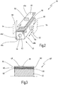
- FIG. 4 shows an embodiment with a main body 42 ', in the outer longitudinal sides grooves 70 extend.
- the grooves 70 serve to receive adhesive plug 72, as shown in FIG. 5 is shown in cross section.
- the adhesive plugs 72 are glued both at the bottom of the cover plates 46 and at the bottom of the grooves 70.
- it is a permanently elastic adhesive.
- the grooves 70 have a clear inner diameter d, which is significantly larger than the corresponding outer diameter of the adhesive plug 72, so that in each case a gap 74 remains laterally of the adhesive plug 72. Due to the gaps 74, the adhesive plug 72 can move laterally in the grooves 70 and the cover plates 46 can follow this lateral movement despite the fixation on the main body 42 '. Accordingly, the cover plates 46 are largely tension-free attached to the base body 42 despite different thermal expansion coefficients.
- each cover plate 46 can move both longitudinally and transversely with respect to the main body 42.
- a plurality of local splices 58 may be provided over the length of the main body 42 '.
- the base body 42 has only one longitudinal groove 70 on each longitudinal side which runs approximately centrally to the longitudinal side, thus covering the cover plate 46 directly and to the left of the groove 70 directly on the corresponding longitudinal side of the base body 42", advantageously again an adhesive oil (not shown) between the underside of the cover plate 46 and the main body 42 "Here it is preferred if the air bearings are not centrally supported on the guide surface 48, but laterally (to the right and / or to the left) offset to the The air bearings 50, 52 are thus supported in areas of the guide surface 48, which is indicated at reference numeral 76. As in FIG. 6 is shown, in this embodiment, in each case at least two air bearings are used on each guide surface 48.
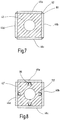
- FIG. 7 shows an embodiment in which a base 42 similar to that of FIG. 2 is used.
- the cover plates 46a are 46d at their outer edges 80 connected to each other, as shown at reference numeral 82.
- the connection is made using a permanently elastic adhesive 82.
- the cover plates 46a-46d are in turn mounted on the base body 42 via an adhesive oil 60 (not shown here).
- a local splice 58, as in FIG. 2 can also be used. It can in the embodiment according to FIG. 7 but also omitted.
- the cover plates are held by their mutual elastic connection on the base body 42.
- FIG. 8 shows a further embodiment for fastening the cover plates 46a - 46d to a base 42 ', which in turn has longitudinal grooves 70' here.
- the longitudinal grooves 70 ' here are conical or otherwise formed with an undercut.
- On the back of each cover plate 46a - 46d one or more spring elements 86 are fixed, for example glued.
- the spring elements 86 engage in the grooves 70 'and hold the cover plates 46a-46d due to their spring force in the grooves 70'. Since the spring elements 46 are flexible and, moreover, can move in the longitudinal grooves 70 ', the cover plates 46a-46d are fastened to the base body 42 largely free of tension.
- an adhesive oil 60 (not shown) or the like may be provided between the underside of the cover plates 46a-46d and the base body 42 '.
- the scale needed for the scale 24 may be applied directly to one of the cover plates 46a-46d.
- other guide bodies of the coordinate measuring machine 10 may be formed in the manner according to the invention.
- a cover plate 46 can be fastened to a base body 42 with the aid of external clips, brackets or the like, the clips or brackets then engaging around the cover plate 46 in the edge region.
- the fixing of the cover plate to the base body is at most in places rigid, so that the cover plate can move at least partially relative to the base body.
- cover plates are completely corrosion-free, other materials, including processed metals, can also be used for the cover plates.
Claims (14)
- Machine de mesure ou d'usinage de pièces (30), en particulier appareil de mesure de coordonnées, avec une tête de machine (26), qui est déplaçable par rapport à un porte-pièce (12), et avec un bâti de machine (14, 16, 18), sur lequel au moins la tête de machine (26) est disposée, dans laquelle le bâti de machine (14, 16, 18) présente au moins un corps de guidage (40) avec au moins une face de guidage (48) pour un palier d'air (50, 52) ainsi qu'un corps opposé (54), qui est appuyé sur la face de guidage (48) au moyen du palier d'air (50, 52), et dans laquelle le corps de guidage (40) et le corps opposé (54) sont déplaçables l'un par rapport à l'autre le long de la face de guidage (48), dans laquelle le corps de guidage (40) comprend un corps de base porteur (42) et une plaque de couverture (46), qui est disposée sur le corps de base (42) et qui forme la face de guidage (48) pour le palier d'air (50, 52), caractérisée en ce que la plaque de couverture (46) est en verre, en particulier en verre flotté.
- Machine selon la revendication 1, caractérisée en ce que le corps de base (42) et la plaque de couverture (46) sont fabriqués en des matériaux différents.
- Machine selon la revendication 1 ou 2, caractérisée en ce que le corps de base (42) possède un premier coefficient de dilatation thermique, en ce que la plaque de couverture (46) possède un deuxième coefficient de dilatation thermique, et en ce qu'au moins un élément intermédiaire (64, 66) est disposé entre la plaque de couverture (46) et le corps de base (42), élément qui possède un troisième coefficient de dilatation thermique, dans laquelle le troisième coefficient de dilatation thermique se situe, par sa grandeur, entre le premier et le deuxième coefficients de dilatation thermique.
- Machine selon l'une quelconque des revendications 1 à 3, caractérisée en ce que la plaque de couverture (46) s'applique de façon largement congruente sur le corps de base (42).
- Machine selon l'une quelconque des revendications 1 à 4, caractérisée en ce que la plaque de couverture (46) est disposée au moins partiellement de façon mobile sur le corps de base (42).
- Machine selon l'une quelconque des revendications 1 à 5, caractérisée en ce que la plaque de couverture (46) et le corps de base (42) sont rigidement assemblés l'un à l'autre par points (58).
- Machine selon l'une quelconque des revendications 1 à 6, caractérisée en ce que la plaque de couverture (46) est fixée sur le corps de base (42) à l'aide d'éléments de maintien élastiques (72; 86).
- Machine selon la revendication 7, caractérisée en ce que les éléments de maintien (72; 86) sont disposés en dessous de la plaque de couverture (46).
- Machine selon la revendication 8, caractérisée en ce que les éléments de maintien (72; 86) sont disposés dans au moins un creux (70).
- Machine selon la revendication 9, caractérisée en ce que ledit au moins un creux (70) présente, parallèlement à la plaque de couverture (46), un diamètre intérieur (d), qui est sensiblement plus grand qu'un diamètre extérieur correspondant des éléments de maintien (72).
- Machine selon la revendication 9 ou 10, caractérisée en ce que ledit au moins un creux (70) est une rainure, qui court sur le corps de base (42).
- Machine selon l'une quelconque des revendications 9 à 11, caractérisée en ce que le palier d'air (76) est appuyé sur la face de guidage (48) en décalage par rapport aux creux (70).
- Machine selon l'une quelconque des revendications 1 à 12, caractérisée en ce que le corps de base (42) présente au moins un premier et un deuxième longs côtés, sur lesquels au moins une première et une deuxième plaques de couverture (46ad) sont disposées.
- Machine selon la revendication 13, caractérisée en ce que la première et la deuxième plaques de couverture (46a-d) sont élastiquement reliées l'une à l'autre.
Applications Claiming Priority (2)
| Application Number | Priority Date | Filing Date | Title |
|---|---|---|---|
| DE102006022501A DE102006022501A1 (de) | 2006-05-08 | 2006-05-08 | Maschine zum Vermessen oder Bearbeiten von Werkstücken, insbesondere Koordinatenmessgerät |
| PCT/EP2007/003697 WO2007128431A2 (fr) | 2006-05-08 | 2007-04-26 | Machine de mesure ou d'usinage de pièces, notamment appareil de mesure de coordonnées |
Publications (2)
| Publication Number | Publication Date |
|---|---|
| EP2018511A2 EP2018511A2 (fr) | 2009-01-28 |
| EP2018511B1 true EP2018511B1 (fr) | 2017-06-28 |
Family
ID=38566985
Family Applications (1)
| Application Number | Title | Priority Date | Filing Date |
|---|---|---|---|
| EP07724627.0A Expired - Fee Related EP2018511B1 (fr) | 2006-05-08 | 2007-04-26 | Machine de mesure ou d'usinage de pièces, notamment appareil de mesure de coordonnées |
Country Status (3)
| Country | Link |
|---|---|
| EP (1) | EP2018511B1 (fr) |
| DE (1) | DE102006022501A1 (fr) |
| WO (1) | WO2007128431A2 (fr) |
Families Citing this family (10)
| Publication number | Priority date | Publication date | Assignee | Title |
|---|---|---|---|---|
| DE102008046070A1 (de) * | 2008-09-05 | 2010-03-11 | Klaus Unger | Vorrichtung zur abtragenden Bearbeitung großer Werkstücke |
| WO2012099586A1 (fr) * | 2011-01-20 | 2012-07-26 | Carl Zeiss Industrial Metrology, Llc | Élément de chemin de guidage en céramique modulaire |
| WO2013083730A1 (fr) | 2011-12-06 | 2013-06-13 | Hexagon Technology Center Gmbh | Machine de mesure de coordonnées comportant un appareil de prise de vue |
| EP2610577B1 (fr) * | 2011-12-30 | 2018-01-24 | Hexagon Metrology S.p.A. | Procédé de production d'un élément de barre d'une machine de mesure de coordonnées et machine de mesure fournie avec cet élément de barre |
| WO2013110337A1 (fr) | 2012-01-26 | 2013-08-01 | Carl Zeiss Industrielle Messtechnik Gmbh | Machine comprenant un palier fluide précontraint amélioré |
| US10646883B2 (en) | 2017-04-19 | 2020-05-12 | Renishaw Plc | Contamination trap |
| EP3392610B1 (fr) | 2017-04-19 | 2022-02-23 | Renishaw PLC | Support de palier |
| JP2020517939A (ja) | 2017-04-19 | 2020-06-18 | レニショウ パブリック リミテッド カンパニーRenishaw Public Limited Company | 測定装置カウンターバランス |
| EP3393023A1 (fr) | 2017-04-19 | 2018-10-24 | Renishaw PLC | Supports de moteur linéaire |
| CN110537076B (zh) | 2017-04-19 | 2021-09-03 | 瑞尼斯豪公司 | 支承布置 |
Citations (1)
| Publication number | Priority date | Publication date | Assignee | Title |
|---|---|---|---|---|
| DE3515685A1 (de) * | 1985-05-02 | 1986-11-06 | Mauser-Werke Oberndorf Gmbh, 7238 Oberndorf | Pinole fuer koordinaten-messmaschine |
Family Cites Families (13)
| Publication number | Priority date | Publication date | Assignee | Title |
|---|---|---|---|---|
| JPS5777905A (en) * | 1980-10-31 | 1982-05-15 | Mitsutoyo Mfg Co Ltd | Measurement of three-dimensional measuring machine |
| JPH02278009A (ja) * | 1989-04-20 | 1990-11-14 | Ntn Corp | 静圧気体軸受 |
| DE3936463A1 (de) * | 1989-11-02 | 1991-05-08 | Zeiss Carl Fa | Koordinatenmessgeraet |
| US5036236A (en) * | 1990-05-07 | 1991-07-30 | Hughes Aircraft Company | Air gap matching proximity sensor for magnetic bearings |
| JPH04145219A (ja) * | 1990-10-05 | 1992-05-19 | Nec Corp | 空気軸受け式ガイド |
| GB9207259D0 (en) * | 1992-04-02 | 1992-05-13 | Renishaw Metrology Ltd | Workpiece measuring machine |
| DE19510998C2 (de) * | 1995-03-25 | 1998-09-03 | Heidenhain Gmbh Dr Johannes | Positionsmeßeinrichtung |
| DE69820921T2 (de) * | 1997-05-07 | 2004-10-28 | Mitutoyo Corp., Kawasaki | Verfahren und Instrument mit Taster zur Messung der Innen- oder Aussendimension eines Objektes |
| US6238092B1 (en) * | 1999-06-01 | 2001-05-29 | Tru-Stone Corporation | Air bearing for a motion system |
| DE10159442B4 (de) * | 2000-12-22 | 2006-11-02 | Schott Ag | Kalibrierkörper für ein Koordinatenmessgerät |
| DE10120553A1 (de) * | 2001-04-26 | 2002-10-31 | Werth Messtechnik Gmbh | Lagerung für insbesondere ein Koordinatenmessgerät |
| US6837114B2 (en) * | 2003-03-21 | 2005-01-04 | Carmar Technology Co., Ltd. | Three-dimensional measure device with air bearings |
| US6829838B1 (en) * | 2003-09-09 | 2004-12-14 | Hexagon Metrology Ab | Temperature compensation system for a coordinate measuring machine |
-
2006
- 2006-05-08 DE DE102006022501A patent/DE102006022501A1/de not_active Withdrawn
-
2007
- 2007-04-26 EP EP07724627.0A patent/EP2018511B1/fr not_active Expired - Fee Related
- 2007-04-26 WO PCT/EP2007/003697 patent/WO2007128431A2/fr active Application Filing
Patent Citations (1)
| Publication number | Priority date | Publication date | Assignee | Title |
|---|---|---|---|---|
| DE3515685A1 (de) * | 1985-05-02 | 1986-11-06 | Mauser-Werke Oberndorf Gmbh, 7238 Oberndorf | Pinole fuer koordinaten-messmaschine |
Also Published As
| Publication number | Publication date |
|---|---|
| DE102006022501A1 (de) | 2007-11-15 |
| WO2007128431A3 (fr) | 2008-08-21 |
| WO2007128431A2 (fr) | 2007-11-15 |
| EP2018511A2 (fr) | 2009-01-28 |
Similar Documents
| Publication | Publication Date | Title |
|---|---|---|
| EP2018511B1 (fr) | Machine de mesure ou d'usinage de pièces, notamment appareil de mesure de coordonnées | |
| EP2697600B1 (fr) | Dispositif et procédé pour mesurer l'épaisseur d'un objet à mesurer | |
| EP2247915B1 (fr) | Table xy comprenant un système de mesure pour la détermination de position | |
| DE19859360C2 (de) | Werkzeugmaschine mit piezoelektrischer Positionskorrektureinrichtung | |
| CH679334A5 (fr) | ||
| DE102016201922B4 (de) | Linearführung, insbesondere für ein Koordinatenmessgerät | |
| EP2302332B1 (fr) | Dispositif de mesure de longueur | |
| EP0372302A2 (fr) | Appareil de mesure de coordonnées avec un ou plusieurs éléments d'aluminium | |
| EP0264801A1 (fr) | Support pour la représentation de la mesure et de la forme | |
| DE19821274A1 (de) | Koordinatenmeßgerät in Brückenbauweise | |
| DE3243275C2 (de) | Meßgerät | |
| DE102011079464A1 (de) | Längenmesseinrichtung | |
| DE10333561B4 (de) | Koordinaten-Meßmaschine | |
| EP1381823B1 (fr) | Support pour appareil de mesure de coordonnees | |
| EP3705850B1 (fr) | Dispositif doté d'un support principal, d'un support intermédiaire agencé sur le support principal et d'une cale agencé sur le support intermédiaire | |
| AT510515B1 (de) | Lünette zur abstützung eines werkstücks einer werkzeugmaschine | |
| DE202006017265U1 (de) | Träger für eine Werkzeugspindel | |
| DE3441426A1 (de) | Koordinatenmessmaschine | |
| DE102017118944B4 (de) | Koordinatenmessgerät | |
| DE102007060606A1 (de) | Koordinatenmessgerät mit Kompensation von thermisch bedingten Längenänderungen für die Koordinatenbestimmung | |
| WO2007093070A1 (fr) | Machine-outil | |
| DE102016221260A1 (de) | Linearführung für ein Koordinatenmessgerät und Koordinatenmessgerät | |
| DE102021200545A1 (de) | Anordnung für eine Positionsmessung | |
| WO2002014012A1 (fr) | Table a mouvements croises pour la realisation de deplacements dans un systeme de coordonnees bidimensionnel | |
| DE102018202772B4 (de) | Halteeinrichtung für eine Luftlagereinrichtung, Koordinatenmessgerät sowie Verfahren zur Herstellung einer Halteeinrichtung |
Legal Events
| Date | Code | Title | Description |
|---|---|---|---|
| PUAI | Public reference made under article 153(3) epc to a published international application that has entered the european phase |
Free format text: ORIGINAL CODE: 0009012 |
|
| 17P | Request for examination filed |
Effective date: 20081204 |
|
| AK | Designated contracting states |
Kind code of ref document: A2 Designated state(s): AT BE BG CH CY CZ DE DK EE ES FI FR GB GR HU IE IS IT LI LT LU LV MC MT NL PL PT RO SE SI SK TR |
|
| AX | Request for extension of the european patent |
Extension state: AL BA HR MK RS |
|
| DAX | Request for extension of the european patent (deleted) | ||
| RBV | Designated contracting states (corrected) |
Designated state(s): DE FR GB IT |
|
| GRAP | Despatch of communication of intention to grant a patent |
Free format text: ORIGINAL CODE: EPIDOSNIGR1 |
|
| INTG | Intention to grant announced |
Effective date: 20170112 |
|
| GRAS | Grant fee paid |
Free format text: ORIGINAL CODE: EPIDOSNIGR3 |
|
| GRAA | (expected) grant |
Free format text: ORIGINAL CODE: 0009210 |
|
| AK | Designated contracting states |
Kind code of ref document: B1 Designated state(s): DE FR GB IT |
|
| REG | Reference to a national code |
Ref country code: GB Ref legal event code: FG4D Free format text: NOT ENGLISH |
|
| REG | Reference to a national code |
Ref country code: DE Ref legal event code: R096 Ref document number: 502007015728 Country of ref document: DE |
|
| REG | Reference to a national code |
Ref country code: DE Ref legal event code: R097 Ref document number: 502007015728 Country of ref document: DE |
|
| PLBE | No opposition filed within time limit |
Free format text: ORIGINAL CODE: 0009261 |
|
| STAA | Information on the status of an ep patent application or granted ep patent |
Free format text: STATUS: NO OPPOSITION FILED WITHIN TIME LIMIT |
|
| 26N | No opposition filed |
Effective date: 20180329 |
|
| PG25 | Lapsed in a contracting state [announced via postgrant information from national office to epo] |
Ref country code: FR Free format text: LAPSE BECAUSE OF NON-PAYMENT OF DUE FEES Effective date: 20180430 |
|
| PGFP | Annual fee paid to national office [announced via postgrant information from national office to epo] |
Ref country code: DE Payment date: 20210420 Year of fee payment: 15 Ref country code: IT Payment date: 20210427 Year of fee payment: 15 |
|
| PGFP | Annual fee paid to national office [announced via postgrant information from national office to epo] |
Ref country code: GB Payment date: 20210421 Year of fee payment: 15 |
|
| REG | Reference to a national code |
Ref country code: DE Ref legal event code: R119 Ref document number: 502007015728 Country of ref document: DE |
|
| GBPC | Gb: european patent ceased through non-payment of renewal fee |
Effective date: 20220426 |
|
| PG25 | Lapsed in a contracting state [announced via postgrant information from national office to epo] |
Ref country code: GB Free format text: LAPSE BECAUSE OF NON-PAYMENT OF DUE FEES Effective date: 20220426 Ref country code: DE Free format text: LAPSE BECAUSE OF NON-PAYMENT OF DUE FEES Effective date: 20221103 |
|
| PG25 | Lapsed in a contracting state [announced via postgrant information from national office to epo] |
Ref country code: IT Free format text: LAPSE BECAUSE OF NON-PAYMENT OF DUE FEES Effective date: 20220426 |