EP2002216B1 - Method for holding a scale on a carrier and arrangement having a carrier and a scale - Google Patents
Method for holding a scale on a carrier and arrangement having a carrier and a scale Download PDFInfo
- Publication number
- EP2002216B1 EP2002216B1 EP07702852.0A EP07702852A EP2002216B1 EP 2002216 B1 EP2002216 B1 EP 2002216B1 EP 07702852 A EP07702852 A EP 07702852A EP 2002216 B1 EP2002216 B1 EP 2002216B1
- Authority
- EP
- European Patent Office
- Prior art keywords
- scale
- carrier
- electrode
- arrangement according
- electrodes
- Prior art date
- Legal status (The legal status is an assumption and is not a legal conclusion. Google has not performed a legal analysis and makes no representation as to the accuracy of the status listed.)
- Active
Links
- 238000000034 method Methods 0.000 title claims description 20
- 239000011521 glass Substances 0.000 claims description 6
- 239000002241 glass-ceramic Substances 0.000 claims description 6
- 239000000758 substrate Substances 0.000 claims description 5
- 230000001419 dependent effect Effects 0.000 claims description 2
- 239000007788 liquid Substances 0.000 claims 2
- 229910052751 metal Inorganic materials 0.000 description 16
- 239000002184 metal Substances 0.000 description 16
- 238000005259 measurement Methods 0.000 description 14
- 239000000463 material Substances 0.000 description 8
- 239000006094 Zerodur Substances 0.000 description 7
- 230000000694 effects Effects 0.000 description 6
- 239000003989 dielectric material Substances 0.000 description 5
- 230000035882 stress Effects 0.000 description 5
- 239000000853 adhesive Substances 0.000 description 4
- 230000001070 adhesive effect Effects 0.000 description 4
- 239000004020 conductor Substances 0.000 description 4
- 230000005484 gravity Effects 0.000 description 4
- 239000004065 semiconductor Substances 0.000 description 4
- 239000007787 solid Substances 0.000 description 4
- 238000005411 Van der Waals force Methods 0.000 description 3
- 229910052782 aluminium Inorganic materials 0.000 description 3
- XAGFODPZIPBFFR-UHFFFAOYSA-N aluminium Chemical compound [Al] XAGFODPZIPBFFR-UHFFFAOYSA-N 0.000 description 3
- 239000011248 coating agent Substances 0.000 description 3
- 238000000576 coating method Methods 0.000 description 3
- 239000012535 impurity Substances 0.000 description 3
- 230000015572 biosynthetic process Effects 0.000 description 2
- 239000000428 dust Substances 0.000 description 2
- 230000005684 electric field Effects 0.000 description 2
- 239000011734 sodium Substances 0.000 description 2
- 238000004544 sputter deposition Methods 0.000 description 2
- 229910018072 Al 2 O 3 Inorganic materials 0.000 description 1
- 241000669003 Aspidiotus destructor Species 0.000 description 1
- 101100117236 Drosophila melanogaster speck gene Proteins 0.000 description 1
- DGAQECJNVWCQMB-PUAWFVPOSA-M Ilexoside XXIX Chemical compound C[C@@H]1CC[C@@]2(CC[C@@]3(C(=CC[C@H]4[C@]3(CC[C@@H]5[C@@]4(CC[C@@H](C5(C)C)OS(=O)(=O)[O-])C)C)[C@@H]2[C@]1(C)O)C)C(=O)O[C@H]6[C@@H]([C@H]([C@@H]([C@H](O6)CO)O)O)O.[Na+] DGAQECJNVWCQMB-PUAWFVPOSA-M 0.000 description 1
- 239000004809 Teflon Substances 0.000 description 1
- 229920006362 Teflon® Polymers 0.000 description 1
- 230000001133 acceleration Effects 0.000 description 1
- 238000004026 adhesive bonding Methods 0.000 description 1
- 230000032683 aging Effects 0.000 description 1
- 230000002238 attenuated effect Effects 0.000 description 1
- TZCXTZWJZNENPQ-UHFFFAOYSA-L barium sulfate Chemical compound [Ba+2].[O-]S([O-])(=O)=O TZCXTZWJZNENPQ-UHFFFAOYSA-L 0.000 description 1
- 230000009286 beneficial effect Effects 0.000 description 1
- 238000004364 calculation method Methods 0.000 description 1
- 239000000969 carrier Substances 0.000 description 1
- 230000008878 coupling Effects 0.000 description 1
- 238000010168 coupling process Methods 0.000 description 1
- 238000005859 coupling reaction Methods 0.000 description 1
- 230000007423 decrease Effects 0.000 description 1
- 230000002950 deficient Effects 0.000 description 1
- 238000000151 deposition Methods 0.000 description 1
- 230000008021 deposition Effects 0.000 description 1
- 230000002349 favourable effect Effects 0.000 description 1
- 239000011888 foil Substances 0.000 description 1
- 239000011810 insulating material Substances 0.000 description 1
- 150000002500 ions Chemical class 0.000 description 1
- 238000005304 joining Methods 0.000 description 1
- 238000001459 lithography Methods 0.000 description 1
- 238000004519 manufacturing process Methods 0.000 description 1
- 150000002739 metals Chemical class 0.000 description 1
- 239000012811 non-conductive material Substances 0.000 description 1
- 239000002245 particle Substances 0.000 description 1
- 230000002093 peripheral effect Effects 0.000 description 1
- 238000000623 plasma-assisted chemical vapour deposition Methods 0.000 description 1
- 239000002985 plastic film Substances 0.000 description 1
- 229920006255 plastic film Polymers 0.000 description 1
- 229910052708 sodium Inorganic materials 0.000 description 1
- 238000009827 uniform distribution Methods 0.000 description 1
Images


Classifications
-
- G—PHYSICS
- G01—MEASURING; TESTING
- G01D—MEASURING NOT SPECIALLY ADAPTED FOR A SPECIFIC VARIABLE; ARRANGEMENTS FOR MEASURING TWO OR MORE VARIABLES NOT COVERED IN A SINGLE OTHER SUBCLASS; TARIFF METERING APPARATUS; MEASURING OR TESTING NOT OTHERWISE PROVIDED FOR
- G01D5/00—Mechanical means for transferring the output of a sensing member; Means for converting the output of a sensing member to another variable where the form or nature of the sensing member does not constrain the means for converting; Transducers not specially adapted for a specific variable
- G01D5/26—Mechanical means for transferring the output of a sensing member; Means for converting the output of a sensing member to another variable where the form or nature of the sensing member does not constrain the means for converting; Transducers not specially adapted for a specific variable characterised by optical transfer means, i.e. using infrared, visible, or ultraviolet light
- G01D5/32—Mechanical means for transferring the output of a sensing member; Means for converting the output of a sensing member to another variable where the form or nature of the sensing member does not constrain the means for converting; Transducers not specially adapted for a specific variable characterised by optical transfer means, i.e. using infrared, visible, or ultraviolet light with attenuation or whole or partial obturation of beams of light
- G01D5/34—Mechanical means for transferring the output of a sensing member; Means for converting the output of a sensing member to another variable where the form or nature of the sensing member does not constrain the means for converting; Transducers not specially adapted for a specific variable characterised by optical transfer means, i.e. using infrared, visible, or ultraviolet light with attenuation or whole or partial obturation of beams of light the beams of light being detected by photocells
- G01D5/347—Mechanical means for transferring the output of a sensing member; Means for converting the output of a sensing member to another variable where the form or nature of the sensing member does not constrain the means for converting; Transducers not specially adapted for a specific variable characterised by optical transfer means, i.e. using infrared, visible, or ultraviolet light with attenuation or whole or partial obturation of beams of light the beams of light being detected by photocells using displacement encoding scales
- G01D5/34707—Scales; Discs, e.g. fixation, fabrication, compensation
Definitions
- the invention relates to a method for holding a scale on a carrier.
- a scale is to be attached to one of the machine parts, and a scanning unit is attached to the other of the mutually movable machine parts. In the position measurement, a measurement graduation of the scale is scanned by the scanning unit.
- a short, possibly limited to the contact surface force path can be achieved for example by wringing (atomic van der Waals forces).
- wringing atomic van der Waals forces
- scales of glass or glass ceramic are used with negligible expansion coefficient.
- These standards can be processed well, so that here the wringing of optically polished counter-surfaces is common, as in the DE 101 53 147 A1 described. Wringing is a very drift-stable attachment method for standards.
- the outer edges of an impacted scale can therefore be unstable if alternating stresses occur at the edge (eg due to acceleration or temperature variations) and as a result these edge zones are repeatedly peeled off and blown up.
- an exploded scale is difficult to detach again from the carrier and thus an exchange of a damaged scale is difficult.
- Another known method for holding a scale on a carrier is the gluing in the region of the support surface.
- shrinkage processes of the adhesive can lead to stresses between the support and the scale, which lead to non-reproducible length errors on a scale.
- These shrinkage processes in the adhesive are z. B. by aging of the adhesive, induced by changes in temperature and humidity. Glued-on scales are also difficult to remove, they can hardly be detached without residue.
- the object of the invention is to provide a method by which a scale can be kept as drift-stable as possible but detachable on a support.
- Another object of the invention is to provide an arrangement with a carrier and with a detachable and yet stably fixed scale.
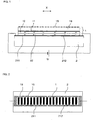
- each of the bodies to be clamped to each other 1 and 2 each have a live electrode 211, 212 as the anode or cathode, to which a voltage U is applied and thereby the two opposing electrodes 211, 212 are charged opposite.
- the carrier 2 is in this case as a live electrode (electrically conductive material or semiconductor material) or with a live electrode (in particular coating with an electrically conductive material or semiconductor material) and the scale 1 having a measuring graduation 15 as counterelectrode (made of electrically conductive material or semiconductor material or Coating a non-conductive material scale with an electrically conductive material or semiconductor material).
- a dielectric 12, 22 is provided, in the illustrated example, a layer of dielectric 12 on the substrate 19 of the scale 1 and a layer of dielectric 22 on the support 2 is attached.
- the scale 1 and the carrier 2 are each provided with a power connection.
- the live electrodes which are connected to the voltage source are arranged together on one of the bodies to be connected and the electrode on the other body forms a kind of coupling electrode in which counter-charges form partially in the region opposite to the live electrodes.
- the carrier 2 or the scale 1 the two live, so contacted electrodes.
- the Bipolar clamping is preferable because the contacting effort can be limited to one component.
- the bipolar electrostatic clamping is therefore preferably used.
- both live electrode anode 211 and cathode 212 are provided together on the carrier 2 and the counter electrode is formed in each case in an electrically conductive body 11 of the scale 1 from.
- the bipolar electrostatic clamping is therefore realized and the live electrodes 211, 212 are arranged jointly on the carrier body 2. This arrangement facilitates the handling of the scale 1, since only the carrier body 2 must be provided with electrical contacts and leads.
- FIG. 1 shows the side view of the carrier 2 with the held by electrostatic clamping scale 1 and FIG. 2 the top view.
- the scale 1 has a measuring graduation 15 in the form of an incremental measuring graduation 15 which is photoelectrically scanned for position measurement in the measuring direction X.
- the measuring graduation 15 may be a reflective amplitude grating or a phase grating, which serves in a known manner for highly accurate interferential position measurement.
- Favorable dielectrics are Si 3 N 4 , Ta 2 O 5 , Y 2 O 3 , Al 2 O 3 or AlN. They have a high relative dielectric constant ⁇ R and a high dielectric strength.
- Typical layer thicknesses for the metal layers 11 and 211, 212 forming the electrodes are between 20 nm and 2 ⁇ m, those for the dielectric 12 and 22 between 50 nm and 400 ⁇ m.
- transparent and electrically conductive layers "TCO" thin conductive layer
- ITO indium conductive layer
- ZnO zinc oxide
- the mutually contacting contact surfaces of scale 1 and carrier 2 are each formed by the dielectric 12 and 22. These contact surfaces are executed over a large area at least largely over the entire extent of the scale 1.
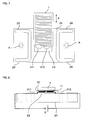
- the surfaces on which the scale 1 has contact with the carrier 2 can also be designed in an advantageous manner such that the entire facing surfaces of scale 1 and carrier 2 (mounting surfaces) do not touch each other.
- spaced elevations 23 are formed on the scale 1 and / or on the carrier 2, which form the contact surfaces. This has the advantage that when joining scale 1 and carrier 2, air can escape from the intermediate space through the channels 24 between the elevations 23 to the outside.
- Such embodiments are in the FIGS. 3 to 9 . 11 . 12 . 15 . 16 and 18 shown.
- the dielectric 22 of the support 2 is structured by elevations 23 and depressions 24 are formed in it alternately.
- the contact surface is thereby small compared to the mounting surface and distributed in many small individual surfaces over the mounting surface.
- the requirement for dust-free mounting surface decreases considerably.
- the structuring of the dielectric 22 can be achieved either by a partial reduction of the thickness or by a complete removal.
- the formation of elevations 23 and depressions 24 by structuring can take place in a manner not shown alternatively or additionally also on the scale 1, by alternatively or additionally structuring the dielectric 12 of the scale 1 accordingly.
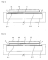
- elevations 23, which form lying between the elevations 23 and outwardly leading channels 24 may also be provided by a structured metal layer 11 of the scale 1 and / or a metal layer 211, 212 of the carrier 2.
- a height profile is created and the dielectric 12, 22 applied flat, as in FIG. 4 is illustrated by the metal layers 211, 212 of the carrier 2.
- the channels 24 are preferably open all the way to the outer surrounding area, so that a pressure equalization can take place and if necessary trapped air can escape.
- the elevations 23 are placed as contact surfaces in the area of Bessel points an elongated scale 1.
- the electrodes 211, 212 are arranged symmetrically to the Bessel points and thus to the support surfaces, so that in the calculation of the support no resulting torque acts on the scale 1.
- the advantage of this embodiment is that the flatness of the support 2 has at most a negligible influence on the tension and flatness of the scale 1 and therefore does not have to be manufactured so precisely. In practice, one achieves extremely high accuracy of a position measuring device with such an arrangement of scale 1 and carrier 2.
- the support 2 consists of support elements 28 on a base body 26.
- the support elements 28 may be sprinkled on the base body 26, glued, clamped or screwed. Between the support elements 28 and the main body 26 and solid joints can be arranged, which on the one hand not transfer the Anschraub mechanism on the scale 1 and / or on the other hand allow a maximum force-free length extension of scale 1 relative to the base body 26.
- FIG. 7 is a plan view of a support element 25 with arranged on both sides of the scale 1 solid joints 29 shown.
- the solid joints 29 are transverse to the measuring direction X extending material webs, which allow a direction of measurement X directed movement of the support element 25 relative to the screw A.
- the attachment point A is used for stationary fixation of the support element 25 at one in the FIGS. 5 and 6 illustrated basic body 26.
- FIG. 8 shows a cross section of this arrangement.
- the attached to the support member 25 electrodes 211, 212 are connected to an electrical voltage U and cooperate with the scale 1 attached to the electrode 11.
- the dielectric 12 is provided in each case.
- FIG. 9 shows the electrostatic clamping of a flat two-dimensionally extended scale 1, as is common, for example, in two-dimensionally measuring cross-grating measuring devices.
- three offset by 120 °, symmetrically arranged elevations 23 are provided.
- the radial distance from the center is chosen so that, in spite of gravity, the lowest possible angle of inclination or the greatest possible flatness is achieved.
- the electrodes 11 on the scale 1 should here remain essentially limited to the electrode surfaces 211, 212 of the carrier 2 and are advantageously designed bipolar.
- Two independent pairs of electrodes 211, 212 and 213, 214 are provided, which are supplied by two independent voltage sources U1, U2. If one of the power supplies fails, the scale 1 still remains attached. Of course, even more pairs of electrodes and independent power supplies may be provided to increase safety. This embodiment is particularly advantageous when batteries are provided as voltage sources.
- the electrode structure 211, 212 and 213, 214, which is each assigned to a voltage source, should as far as possible be distributed over the mounting surface.
- the embodiment according to FIG. 11 corresponds largely to the execution according to FIG. 3 , only that additional mechanical fasteners 3 are provided, which nevertheless securely hold the scale 1 in case of failure of the power supply U.
- the fasteners 3 fix the scale 1 advantageously at locations that are located away from a measurement pitch 15 for position measurement.
- the fastening elements 3 may be spring elements 3, which engage milled pockets in edge surfaces of the scale 1.
- FIG. 12 illustrated embodiment combines the type of attachment wringing with the electrostatic clamping.
- the opposite outer surfaces of the dielectric 12 of the scale 1 and the dielectric 22 of the carrier 2 are sprinkled together. If the roughness of the dielectrics 12, 22 is not sufficiently small, they still need to be polished slightly after the layer deposition (sputtering, sputtering or plasma process PECVD). With this attachment, you do not need a redundant design of multiple pairs of electrodes, as always a sufficient contact pressure is present.
- the electrostatic clamping prevents the peeling of the impact, since the long-range electrostatic forces even in poor local contact conditions in which the short-range van der Waals forces are already very low or no longer exist, a sufficient Ensure contact pressure.
- the contact surfaces are interrupted, so that during assembly no air bubbles are trapped in the contact surfaces, or the remaining air remains in the contact surfaces can escape in a short time.
- the formation of the electrostatic clamping corresponds to the embodiment according to FIG. 3 ,
- the dielectric 12, 22 of the preceding examples is realized by a thin foil 4, which is introduced between the scale 1 and the carrier 2.
- the scale 1 and the carrier 2 must be provided in this case only with a simple electrode layer 11, 211, 212, which can be done in a Bedampfungs Republic. The costs can be significantly reduced.
- a film 4 are plastic films such as Teflon in question, but also thin glass sheets.
- the film thicknesses are advantageously in the range 20-400 microns. This type of fastening is particularly advantageous if scales 1 made of metal are used. They can be used without coating since they themselves form the electrode 11.
- An oil film 5 is introduced between the dielectric 12 of the scale 1 and the outer metal layer 211, 212 of the carrier 2. He remains limited due to its Kapilar tendency in the very thin gap area.
- This oil film 5 prevents, on the one hand, that small volumes of air are trapped between the scale 1 and the support 2, in which corona discharges can also occur at high field strength.
- the scale 1 can slide over the oil film 5 and thus retain its length. This type of mounting is particularly interesting when the support 2 has a high thermal expansion (such as aluminum) and scale 1 has a very small thermal expansion (such as Zerodur).
- FIGS. 15 and 16 is an advantageous kinematic three-point mounting a flat scale 1 (in particular a Cross grid plate) suspended from the carrier 2 is shown.
- FIG. 15 shows the top view of the spatial arrangement of the electrodes 211, 212 on the support 2 and FIG. 16 a scale in the range of two support points with the scale 1.
- the scale 1 again has the electrode 11 and the carrier 2, the live electrodes 211 and 212 are arranged.
- the scale 1 is only on three spaced-apart arranged elevations 23 on the carrier 2.
- the elevations 23 are formed by punctiform regions of the dielectric 22 of the carrier 2.
- This deformation can be compensated by a corresponding contact pressure, which is generated by the electrostatic clamping and which corresponds and counteracts the gravity exactly, but which must be significantly lower than the contact pressure in the area of the contact surfaces.
- a corresponding contact pressure which is generated by the electrostatic clamping and which corresponds and counteracts the gravity exactly, but which must be significantly lower than the contact pressure in the area of the contact surfaces.
- electrodes 211, 212 of larger area are arranged outside the elevations 23 than in the remaining area.
- the goal is to achieve a high evenness and thus a high accuracy of scale 1.
- the lower contact pressure outside the elevations 23 and thus outside the contact surfaces can be achieved in a simple manner by a corresponding structuring with narrow but widely spaced electrode surfaces 211, 212. In the area of the contact points, however, the area occupation with electrodes 211, 212 must be high.
- the elevations 23 (contact surfaces) and the remaining mounting surfaces can each be occupied by two independent pairs of electrodes and supplied with separate voltage sources. By
- Electrode structures must have small lateral spacings between 1 .mu.m and 500 .mu.m in order to generate as inhomogeneous as possible an electric field.
- the substrate 19 of the scale 1 consists in this embodiment of a nearly insulating material, but having a certain proportion of mobile charges.
- Movable charges can be, for example, ions (eg Na +) or ionizable impurities which allow the charge to jump from impurity to impurity.
- Suitable materials include, for example, sodium-containing glass types and Zerodur.
- this effect of the slowly decaying holding force can also be used for all the embodiments explained above if dielectrics 12 or 22 or 4 are used which have movable charges. In most cases, the contact pressure is also significantly higher, since the distances between the opposite charges are lower (Johnson Rahbeck effect).
- the utilization of this effect is particularly advantageous for fixing the scale 1 for highly accurate photoelectric position measurement, since here scales 1 made of glass ceramic, in particular Zerodur be used.
- the above-mentioned Johnson Rahbeck effect can also lead to undefined contact pressures when the density of the moving Charges or their mobility is unevenly distributed. Also, the slow increase of the contact pressures due to the low mobility in combination with not perfectly level scales 1 or carriers 2 can lead to changing voltages on the scale 1. In these cases, it is beneficial to suppress the Johnson Rahbeck effect.
- An embodiment of this is in FIG. 18 shown.
- the scale 1 is coated on the underside with a planar electrode 11, for example a metal layer 11.
- the carrier 2 carries a pair of electrodes 211, 212, which is covered with a dielectric 22, and which is preferably made thicker to form elevations 23, which form the contact points. The region between the elevations 23 forms the channels 24.
- an electrically conductive layer for example a metal layer 6 is applied to the elevations 23 of the dielectric 22, which is in electrical contact with the electrode 11 of the scale 1.
- the dielectric 22 now has no direct contact with the opposite electrode 11 of the scale 1.
- the influence of the mobile charges in the dielectric 22 is thereby considerably attenuated.
- the contact pressure arises only in the areas outside the contact surfaces, ie outside of the elevations 23rd
- the layer structure of the scale 1 can be selected such that mechanical stresses caused in the layers are compensated.
- the layer material and the layer thicknesses are determined so that in these layers caused mechanical stresses compensate each other.
- the layers may have a fine structuring.
- multi-dimensional position measurement scales 1 are increasingly used with a two-dimensional measurement graduation 15, in particular with an intersecting measurement graduation, also called a cross lattice. It is necessary to attach relatively large scale 1 (about 40 cm x 40 cm) on a surface of a support 2. Particularly in the case of lithographic devices in which the support 2, to which the scale 1 is to be fastened, consists of glass ceramic (eg ZERODUR) with a coefficient of expansion close to zero, the invention can be used advantageously.
- Such a machine with a scale with a two-dimensional measuring graduation is in the US 2004/0263846 A1 to which reference is hereby made.
- a plurality of scales 1 may be attached two-dimensionally next to each other like a mosaic on a machine surface 2 of, for example, 1 m ⁇ 2 m, in order to cover the required measuring range of approximately 1 m ⁇ 2 m.
- the scales 1 with the particular photoelectrically scanned measuring graduation 15 are in the required precision namely only in sizes of about 40cm x 40cm relatively uncomplicated in the required quality manufacturable.
- Each of these scales 1 with a two-dimensional measuring graduation 15, also called a cross grid can now according to the invention be attached to the machine part 2 as a carrier.
- the contact pressure is evenly distributed over the contact surfaces. Even if small dust particles are trapped between the contact surfaces, the contact pressure is hardly affected since the distance dependence drops only with 1 / d 2 . In contrast, the van der Waals forces of an impingement fall with 1 / d 6 and are limited only to atomic distances.
- the contact pressure of a Ansprengung is therefore very uneven and undefined in practice. If the contact pressure is distributed unevenly and the scale and the carrier expand differently thermally, there may be local shifts between scale and carrier, which can not be accepted in high-precision applications.
- the electrostatic connection is solvable, defective standards 1 can be replaced if required.
- the strength of the electrostatic connection with a suitable choice of the dielectric 12 and 22, its thickness and dielectric strength as well as the applied voltage U exceed that of an exposure.
- a temperature of the scale 2 can occur, which leads to measurement errors. In practice, this occurs, for example, at a scale 1 of Zerodur and a carrier 2 with high thermal expansion, such as aluminum.
- the contact pressure clamping force, holding force
- the time intervals between the momentary voltage shutdowns may be based on the typical time intervals for relevant temperature changes. The entire process can be easily controlled electronically without manual intervention.
- the surfaces on which the scale 1 has contact with the carrier 2 can be structured as desired and do not have to be identical to the entire facing area of the scale and the support (mounting surface), as is the case with wringing.
- the scale 1 and / or the carrier 2 in the area of the mounting surfaces or contact surfaces also remain unpolished, which can significantly reduce the cost.
- the demands on the evenness of the mounting surfaces are also eliminated. This too can significantly reduce the manufacturing costs.
Landscapes
- Physics & Mathematics (AREA)
- General Physics & Mathematics (AREA)
- Transmission And Conversion Of Sensor Element Output (AREA)
- Length Measuring Devices With Unspecified Measuring Means (AREA)
- Measurement Of Length, Angles, Or The Like Using Electric Or Magnetic Means (AREA)
Description
Die Erfindung betrifft ein Verfahren zum Halten eines Maßstabs an einem Träger.The invention relates to a method for holding a scale on a carrier.
Zur Messung der Relativlage zweier Maschinenteile ist an einem der Maschinenteile ein Maßstab zu befestigen und am anderen der zueinander beweglichen Maschinenteile eine Abtasteinheit. Bei der Positionsmessung wird eine Messteilung des Maßstabs von der Abtasteinheit abgetastet.To measure the relative position of two machine parts, a scale is to be attached to one of the machine parts, and a scanning unit is attached to the other of the mutually movable machine parts. In the position measurement, a measurement graduation of the scale is scanned by the scanning unit.
Zur hochgenauen Positionsmessung ist es notwendig, dass der Maßstab stabil und driftfrei am Träger gehalten wird. Eine hohe Stabilität und Driftfreiheit im Nano- und Subnanometerbereich verlangt einen äußerst kurzen Kraftweg, der möglichst auf die Kontaktfläche beschränkt bleiben soll und nicht die gesamte Dicke des Maßstabs einschließen sollte.For highly accurate position measurement, it is necessary that the scale is held stable and drift-free on the carrier. High stability and drift freedom in the nano- and subnanometer range requires a very short force path, which should be limited as far as possible to the contact surface and should not include the entire thickness of the scale.
Ein kurzer, möglichst auf die Kontaktfläche beschränkter Kraftweg lässt sich beispielsweise durch Ansprengen (atomare van-der-Waals-Kräfte) erreichen. Dabei werden vorzugsweise Maßstäbe aus Glas oder Glaskeramik mit vernachlässigbarem Ausdehnungskoeffizienten eingesetzt. Diese Maßstäbe lassen sich gut bearbeiten, so dass hier das Ansprengen an optisch polierten Gegenflächen gebräuchlich ist, wie in der
Eine weitere bekannte Methode zum Halten eines Maßstabs an einem Träger ist das Kleben im Bereich der Auflagefläche. Je nach Art des Klebers und Dicke der Klebung kann es durch Schrumpfungsprozesse des Klebers zu Verspannungen zwischen Träger und Maßstab kommen, welche zu nicht reproduzierbaren Längenfehlern im Maßstab führen. Diese Schrumpfungsprozesse im Kleber werden z. B. durch Alterung des Klebers, durch Temperatur- und Luftfeuchteänderungen induziert. Aufgeklebte Maßstäbe sind auch schwer wieder ablösbar, sie lassen sich kaum rückstandsfrei ablösen.Another known method for holding a scale on a carrier is the gluing in the region of the support surface. Depending on the type of adhesive and the thickness of the bond, shrinkage processes of the adhesive can lead to stresses between the support and the scale, which lead to non-reproducible length errors on a scale. These shrinkage processes in the adhesive are z. B. by aging of the adhesive, induced by changes in temperature and humidity. Glued-on scales are also difficult to remove, they can hardly be detached without residue.
Aufgabe der Erfindung ist es, ein Verfahren anzugeben, mit dem ein Maßstab möglichst driftstabil aber lösbar an einem Träger gehalten werden kann.The object of the invention is to provide a method by which a scale can be kept as drift-stable as possible but detachable on a support.
Gelöst wird diese Aufgabe durch ein Verfahren gemäß dem Anspruch 1.This object is achieved by a method according to
Eine weitere Aufgabe der Erfindung ist es, eine Anordnung mit einem Träger und mit einem daran lösbar und trotzdem stabil befestigten Maßstab anzugeben.Another object of the invention is to provide an arrangement with a carrier and with a detachable and yet stably fixed scale.
Gelöst wird diese Aufgabe durch eine Anordnung gemäß dem Anspruch 8.This object is achieved by an arrangement according to claim 8.
Vorteilhafte Ausbildungen der Erfindung sind in den abhängigen Ansprüchen angegeben.Advantageous embodiments of the invention are specified in the dependent claims.
Vorteile der Erfindung sind der Beschreibung der Ausführungsbeispiele zu entnehmen. Diese Ausführungsbeispiele der Erfindung werden nachfolgend anhand der Zeichnungen näher erläutert.Advantages of the invention can be found in the description of the embodiments. These embodiments of the invention are explained below with reference to the drawings.
Es zeigen
Figur 1- ein erstes Ausführungsbeispiel einer Anordnung mit einem Träger und einem daran befestigten Maßstab in einer Seitenansicht;
Figur 2- die Anordnung gemäß
Figur 1 Figur 3- ein zweites Ausführungsbeispiel einer Anordnung mit einem Träger und einem daran befestigten Maßstab in einer Seitenansicht;
Figur 4- ein drittes Ausführungsbeispiel einer Anordnung mit einem Träger und einem daran befestigten Maßstab in einer Seitenansicht;
Figur 5- ein viertes Ausführungsbeispiel einer Anordnung mit einem Träger und einem daran befestigten Maßstab in einer Seitenansicht;
Figur 6- die
Anordnung gemäß Figur 5 in Draufsicht; - Figur 7
- ein fünftes Ausführungsbeispiel einer Anordnung mit einem befestigten Maßstab in einer Draufsicht;
- Figur 8
- die Anordnung gemäß
Figur 7 im Querschnitt; - Figur 9
- ein sechstes Ausführungsbeispiel einer Anordnung mit einem Träger und einem daran befestigten Maßstab in einer Draufsicht;
- Figur 10
- ein siebtes Ausführungsbeispiel einer Anordnung mit einem Träger und einem daran befestigten Maßstab in einer Draufsicht;
Figur 11- ein achtes Ausführungsbeispiel einer Anordnung mit einem Träger und einem daran befestigten Maßstab in einer Seitenansicht;
Figur 12- ein neuntes Ausführungsbeispiel einer Anordnung mit einem Träger und einem daran befestigten Maßstab in einer Seitenansicht;
- Figur 13
- ein zehntes Ausführungsbeispiel einer Anordnung mit einem Träger und einem daran befestigten Maßstab in einer Seitenansicht;
- Figur 14
- ein elftes Ausführungsbeispiel einer Anordnung mit einem Träger und einem daran befestigten Maßstab in einer Seitenansicht;
Figur 15- ein zwölftes Ausführungsbeispiel einer Anordnung mit einem Träger und einem daran befestigten Maßstab in einer Draufsicht;
- Figur 16
- die
Anordnung gemäß Figur 15 im Schnitt; - Figur 17
- ein dreizehntes Ausführungsbeispiel einer Anordnung mit einem Träger und einem daran befestigten Maßstab in einer Seitenansicht;
- Figur 18
- ein vierzehntes Ausführungsbeispiel einer Anordnung mit einem Träger und einem daran befestigten Maßstab in einer Seitenansicht und
Figur 19- ein fünfzehntes Ausführungsbeispiel einer Anordnung mit einem Träger und einem daran befestigten Maßstab in einer Seitenansicht.
- FIG. 1
- a first embodiment of an arrangement with a carrier and a scale attached thereto in a side view;
- FIG. 2
- the arrangement according to
FIG. 1 in plan view; - FIG. 3
- A second embodiment of an arrangement with a carrier and a scale attached thereto in a side view;
- FIG. 4
- a third embodiment of an arrangement with a carrier and a scale attached thereto in a side view;
- FIG. 5
- A fourth embodiment of an arrangement with a carrier and an attached scale in a side view;
- FIG. 6
- the arrangement according to
FIG. 5 in plan view; - FIG. 7
- a fifth embodiment of a device with a fixed scale in a plan view;
- FIG. 8
- the arrangement according to
FIG. 7 in cross-section; - FIG. 9
- a sixth embodiment of an arrangement with a carrier and a scale attached thereto in a plan view;
- FIG. 10
- a seventh embodiment of an arrangement with a carrier and a scale attached thereto in a plan view;
- FIG. 11
- an eighth embodiment of an arrangement with a carrier and a scale attached thereto in a side view;
- FIG. 12
- a ninth embodiment of an arrangement with a carrier and a scale attached thereto in a side view;
- FIG. 13
- a tenth embodiment of an arrangement with a carrier and a scale attached thereto in a side view;
- FIG. 14
- an eleventh embodiment of an arrangement with a carrier and a scale attached thereto in a side view;
- FIG. 15
- A twelfth embodiment of an arrangement with a carrier and a scale attached thereto in a plan view;
- FIG. 16
- the arrangement according to
FIG. 15 on average; - FIG. 17
- A thirteenth embodiment of an arrangement with a carrier and a scale attached thereto in a side view;
- FIG. 18
- a fourteenth embodiment of an arrangement with a carrier and a scale attached thereto in a side view and
- FIG. 19
- a fifteenth embodiment of an arrangement with a carrier and a scale attached thereto in a side view.
Grundlage der Erfindung und somit aller nachfolgenden Ausführungsbeispiele ist die Halterung eines Maßstabs 1 an einem Träger 2 mittels elektrostatischer Klemmung. Diese elektrostatische Klemmung beruht auf der Anziehung zweier entgegengesetzt geladener Körper. Dabei wird der Maßstab 1 gemäß der Erfindung durch direkte elektrostatische Klemmung am Träger 2 befestigt. Durch Anlegen einer elektrischen Spannung U wird ein Potentialgefälle direkt zwischen den aneinander zu haltenden Körpern, nämlich dem Maßstab 1 und dem Träger 2 generiert.Basis of the invention and thus all subsequent embodiments is the support of a
Man unterscheidet zwischen unipolarer elektrostatischer Klemmung und bipolarer elektrostatischer Klemmung. Bei der zeichnerisch nur anhand der
Bei der bipolaren elektrostatischen Klemmung sind die spannungsführenden Elektroden, welche an die Spannungsquelle angeschlossen sind gemeinsam an einem der zu verbindenden Körper angeordnet und die Elektrode am anderen Körper bildet eine Art Koppelelektrode, in der sich partiell im Bereich gegenüberliegend zu den spannungsführenden Elektroden Gegenladungen ausbilden. Dabei kann der Träger 2 oder der Maßstab 1 die beiden spannungsführenden, also kontaktierten Elektroden aufweisen. Die bipolare Klemmung ist zu bevorzugen, da der Kontaktierungsaufwand auf einem Bauteil beschränkt bleiben kann.In bipolar electrostatic clamping, the live electrodes, which are connected to the voltage source are arranged together on one of the bodies to be connected and the electrode on the other body forms a kind of coupling electrode in which counter-charges form partially in the region opposite to the live electrodes. In this case, the
Zur Halterung eines Maßstabs 1 aus Glas oder Glaskeramik (z. B. ZERODUR) wird daher bevorzugt die bipolare elektrostatische Klemmung eingesetzt. Dabei sind beide spannungsführenden Elektroden Anode 211 und Kathode 212 gemeinsam auf dem Träger 2 vorgesehen und die Gegenelektrode bildet sich jeweils in einem elektrisch leitenden Körper 11 des Maßstabs 1 aus. In allen nachfolgend ausführlich erläuterten und besonders vorteilhaften Ausführungen der Erfindung ist daher die bipolare elektrostatische Klemmung realisiert und die spannungsführenden Elektroden 211, 212 sind gemeinsam am Trägerkörper 2 angeordnet. Diese Anordnung erleichtert die Handhabung des Maßstabs 1, da nur der Trägerkörper 2 mit elektrischen Kontakten und Zuleitungen versehen werden muss.For holding a
In allen Figuren werden funktional gleich wirkende Elemente mit dem gleichen Bezugszeichen versehen. Die Dicken der Schichten sind dabei stark vergrößert dargestellt.In all figures, functionally identical elements are provided with the same reference numerals. The thicknesses of the layers are shown greatly enlarged.
In den
Der Maßstab 1 besteht aus einem Substrat 19 aus Glas oder Glaskeramik, z. B. ZERODUR und weist an seiner Unterseite eine Elektrode in Form einer leitfähigen, dünnen Metallschicht 11 auf, die mit einem dünnen Dielektrikum 12 abgedeckt ist. Der Träger 2 hat an seiner Oberseite eine Elektrode in Form einer dünnen Metallschicht 211, 212, die ebenfalls mit einem dünnen Dielektrikum 22 abgedeckt ist. Die Metallschicht 211, 212 des Trägers 2 ist in Form von zwei getrennten spannungsführenden Elektroden 211 und 212 strukturiert, an die durch außen liegende Kontaktstellen eine elektrische Spannung U angelegt wird. Im Beispiel ist die Elektrode 211 als Anode und die Elektrode 212 als Kathode ausgeführt. Durch die Spannung U werden in der Metallschicht 11 des Maßstabs 1 jeweils Gegenladungen gegenüber den Elektroden 211 und 212 induziert, die zu Haltekräften führen, welche den Maßstab 1 an den Träger 2 pressen. Aus zeichnerischen Gründen sind die Ladungen + und - nur schematisch neben den Elektroden 11, 211, 212 gezeichnet. Der entstehende Anpressdruck p lässt sich durch folgende Beziehungen berechnen: ![]()
mit
- ε0:
- Dielektrizitätskonstante des Vakuums (=8,854·10-12 F/m)
- εR:
- relative Dielektrizitätskonstante der Kombination des Dielektrikums 12 des
Maßstabs 1 und des Dielektrikums 22 desTrägers 2 - U:
- angelegte Spannung
- d:
- Gesamtdicke beider Dielektrika 12 und 22
auf Maßstab 1 und Träger 2 - a:
- Luftstrecke (falls vorhanden) zwischen Maßstab 1 und Träger 2
With
- ε 0 :
- Dielectric constant of the vacuum (= 8,854 · 10 -12 F / m)
- ε R :
- Relative dielectric constant of the combination of the dielectric 12 of the
scale 1 and the dielectric 22 of the carrier second - U:
- applied voltage
- d:
- Total thickness of both
dielectrics scale 1 andcarrier 2 - a:
- Air gap (if present) between
scale 1 andcarrier 2
Für einen Anpressdruck von 5 bar und einer relativen Dielektrizitätskonstante εR von 10 benötigt man eine Spannung U = 34 V/µm d, falls die Luftstrecke a=0 ist. Günstige Dielektrika sind Si3N4, Ta2O5, Y2O3, Al2O3 oder AIN. Sie besitzen eine hohe relative Dielektrizitätskonstante εR und eine hohe Durchschlagsfestigkeit.For a contact pressure of 5 bar and a relative dielectric constant ε R of 10, a voltage U = 34 V / μm d is required if the air gap a = 0. Favorable dielectrics are Si 3 N 4 , Ta 2 O 5 , Y 2 O 3 , Al 2 O 3 or AlN. They have a high relative dielectric constant ε R and a high dielectric strength.
Für Ta2O5, das eine relative Dielektrizitätskonstante εR = 28 und eine Durchschlagsfestigkeit bis zu 450 V/µm aufweist, benötigt man für eine Schichtdicke von d = 2 µm nur eine Spannung von U = 24 V, um einen Anpressdruck von 5 bar zu erreichen. Die auftretende Feldstärke bleibt dabei weit unter der Durchschlagsfestigkeit des Dielektrikums.For Ta 2 O 5 , which has a relative dielectric constant ε R = 28 and a dielectric strength of up to 450 V / μm, for a layer thickness of d = 2 μm, only a voltage of U = 24 V is required, for a contact pressure of 5 bar to reach. The occurring field strength remains well below the dielectric strength of the dielectric.
Typische Schichtdicken für die Metallschichten 11 und 211, 212, welche die Elektroden bilden, liegen zwischen 20 nm und 2 µm, diejenigen für das Dielektrikum 12 und 22 zwischen 50 nm und 400 µm. Als Material für die Metallschichten 11 und 211, 212 sind spannungsarme Metalle wie Aluminium vorteilhaft. Für die Elektroden können auch durchsichtige und elektrisch leitfähige Schichten "TCO" (thin conductive layer) wie z.B. ITO, ZnO oder SnO eingesetzt werden. Dies ist dann vorteilhaft, wenn Lichtbündel den transparenten Maßstab 1 und den transparenten Träger 2 durchdringen sollen, was beispielsweise bei der Verwendung in Lithografie-Einrichtungen vorteilhaft sein kann.Typical layer thicknesses for the metal layers 11 and 211, 212 forming the electrodes are between 20 nm and 2 μm, those for the dielectric 12 and 22 between 50 nm and 400 μm. As a material for the metal layers 11 and 211, 212 low-stress metals such as aluminum are advantageous. For the electrodes it is also possible to use transparent and electrically conductive layers "TCO" (thin conductive layer), e.g. ITO, ZnO or SnO. This is advantageous if light bundles are to penetrate the
Bei dem ersten Ausführungsbeispiel werden die sich gegenseitig berührenden Kontaktflächen von Maßstab 1 und Träger 2 jeweils von dem Dielektrikum 12 und 22 gebildet. Diese Kontaktflächen sind großflächig zumindest weitgehend über die gesamte Ausdehnung des Maßstabs 1 ausgeführt.In the first embodiment, the mutually contacting contact surfaces of
Die Flächen, an denen der Maßstab 1 Kontakt mit dem Träger 2 hat (Kontaktflächen) können in vorteilhafter Weise auch derart ausgebildet sein, dass sich nicht die gesamten zugewandten Flächen von Maßstab 1 und Träger 2 (Montageflächen) gegenseitig berühren. Dabei sind am Maßstab 1 und/oder am Träger 2 voneinander beabstandete Erhebungen 23 ausgebildet, welche die Kontaktflächen bilden. Dies hat den Vorteil, dass beim Zusammenfügen von Maßstab 1 und Träger 2 Luft aus dem Zwischenraum durch die Kanäle 24 zwischen den Erhebungen 23 nach außen entweichen kann. Derartige Ausgestaltungen sind in den
Bei dem in
Abwechselnd angeordnete Erhebungen 23, welche zwischen den Erhebungen 23 liegende und nach außen führende Kanäle 24 bilden, können auch durch eine strukturierte Metallschicht 11 des Maßstabs 1 und/oder eine Metallschicht 211, 212 des Trägers 2 geschaffen werden. Dabei wird ein Höhenprofil geschaffen und das Dielektrikum 12, 22 flächig aufgetragen, wie in
Bei der Ausführung gemäß den
Der Träger 2 besteht dabei aus Auflageelementen 28 an einem Grundkörper 26. Die Auflageelemente 28 können am Grundkörper 26 angesprengt, angeklebt, angeklemmt oder angeschraubt sein. Zwischen den Auflageelementen 28 und dem Grundkörper 26 können auch Festkörpergelenke angeordnet sein, welche einerseits die Anschraubkräfte nicht auf den Maßstab 1 übertragen und/oder andererseits eine möglichst kräftefreie Längenausdehnung von Maßstab 1 relativ zum Grundkörper 26 zulassen.The
Eine mögliche Anordnung mit Festkörpergelenken ist in den
Bei der Ausführungsform gemäß
Das Ausführungsbeispiel gemäß
Die in
Beim Ausführungsbeispiel gemäß
Bei dem Ausführungsbeispiel gemäß
In den
Bei der in
Dieser Effekt der langsam abklingenden Haltekraft kann grundsätzlich auch zusätzlich für alle oben erläuterten Ausführungen genutzt werden, wenn Dielektrika 12 bzw. 22 bzw. 4 eingesetzt werden, die bewegliche Ladungen aufweisen. Meist ist dann der Anpressdruck auch deutlich höher, da die Abstände zwischen den entgegengesetzten Ladungen geringer sind (Johnson Rahbeck Effekt). Die Ausnutzung dieses Effekts ist gerade zur Befestigung des Maßstabs 1 zur hochgenauen lichtelektrischen Positionsmessung vorteilhaft, da hier Maßstäbe 1 aus Glaskeramik, insbesondere Zerodur eingesetzt werden.In principle, this effect of the slowly decaying holding force can also be used for all the embodiments explained above if
Der oben erwähnte Johnson Rahbeck Effekt kann allerdings auch zu undefinierten Anpressdrücken führen, wenn die Dichte der beweglichen Ladungen oder ihre Beweglichkeit ungleichmäßig verteilt ist. Auch kann die langsame Zunahme der Anpressdrücke durch die geringe Beweglichkeit in Kombination mit nicht perfekt ebenen Maßstäben 1 oder Trägern 2 zu sich ändernden Spannungen in dem Maßstab 1 führen. In diesen Fällen ist es vorteilhaft, den Johnson Rahbeck Effekt zu unterdrücken. Eine Ausführungsform dazu ist in
Bei allen Ausführungsformen kann der Schichtaufbau des Maßstabs 1 derart gewählt werden, dass in den Schichten hervorgerufene mechanische Spannungen kompensiert werden. Hierzu sind das Schichtenmaterial und die Schichtdicken so bestimmt, dass in diesen Schichten hervorgerufene mechanische Spannungen sich gegenseitig kompensieren. Alternativ können die Schichten (Elektroden und/oder Dielektrika) eine feine Strukturierung aufweisen.In all embodiments, the layer structure of the
In nicht dargestellter Weise können alle Strukturelemente des Maßstabs 1, die für die elektrostatische Klemmung notwendig sind, mit denen des Trägers 2 vertauscht werden.In a manner not shown, all structural elements of the
Wie bereits ausgeführt, werden zur mehrdimensionalen Positionsmessung vermehrt Maßstäbe 1 mit einer zweidimensionalen Messteilung 15, insbesondere mit einer sich kreuzenden Messteilung, auch Kreuzgitter genannt, eingesetzt. Dabei ist es notwendig relativ großformatige Maßstäbe 1 (etwa 40 cm x 40 cm) auf einer Fläche eines Trägers 2 zu befestigen. Besonders bei Lithographie-Geräten, bei denen der Träger 2, an dem der Maßstab 1 zu befestigen ist, aus Glaskeramik (z.B. ZERODUR) mit einem Ausdehnungskoeffizienten nahe Null bestehen, ist die Erfindung vorteilhaft einsetzbar. Eine derartige Maschine mit einem Maßstab mit einer zweidimensionalen Messteilung ist in der
Dabei kann es erforderlich sein, dass mehrere Maßstäbe 1 zweidimensional nebeneinander mosaikartig auf einer Maschinenfläche 2 von beispielsweise 1 m x 2m befestigt werden müssen, um den erforderlichen Messbereich von etwa 1 m x 2m abzudecken. Die Maßstäbe 1 mit der insbesondere lichtelektrisch abtastbaren Messteilung 15 sind in der erforderlichen Präzision nämlich nur in Größen von etwa 40cm x 40cm relativ unkompliziert in der geforderten Qualität fertigbar. Jeder dieser Maßstäbe 1 mit einer zweidimensionalen Messteilung 15, auch Kreuzgitter genannt, kann nun erfindungsgemäß am Maschinenteil 2 als Träger befestigt werden.In this case, it may be necessary for a plurality of
Die grundsätzlichen Vorteile der elektrostatischen Klemmung des Maßstabs 1 an dem Träger 2 sind:
- Der Kraftweg ist extrem kurz und schließt nur den Bereich zwischen der Metallschicht 11 des
Maßstabs 1 und derMetallschicht Trägers 2 ein. Er bleibt damit auf das Volumen des Dielektrikums 12, 22 beschränkt.Der Maßstab 1 und der Träger 2 bleiben damit fast vollständig spannungsfrei. Restspannungen indem Maßstab 1 entstehen in der Praxis nur dann, wenn die Kontaktflächen nicht eben sind. Die Spezifikation der Ebenheiten muss den Anforderungen entsprechend ausgelegt werden.
- The force path is extremely short and includes only the area between the
metal layer 11 of thescale 1 and themetal layer carrier 2. He remains so on the volume of the dielectric 12, 22nd limited. Thescale 1 and thecarrier 2 thus remain almost completely stress-free. Residual stresses in thescale 1 arise in practice only if the contact surfaces are not flat. The specification of the flatness must be interpreted according to the requirements.
Der Anpressdruck ist gleichmäßig auf die Kontaktflächen verteilt. Auch wenn kleine Staubpartikel zwischen den Kontaktflächen eingeschlossen sind, wird der Anpressdruck kaum davon beeinflusst, da die Abstandsabhängigkeit nur mit 1/d2 abfällt. Die van-der-Waals-Kräfte einer Ansprengung fallen dagegen mit 1/d6 ab und bleiben nur auf atomare Abstände beschränkt. Der Anpressdruck einer Ansprengung ist deshalb in der Praxis sehr ungleichmäßig und undefiniert. Wenn der Anpressdruck ungleichmäßig verteilt ist und der Maßstab und der Träger sich unterschiedlich thermisch ausdehnen, kann es zu lokalen Verschiebungen zwischen Maßstab und Träger kommen, was in hochgenauen Anwendungen nicht akzeptiert werden kann.The contact pressure is evenly distributed over the contact surfaces. Even if small dust particles are trapped between the contact surfaces, the contact pressure is hardly affected since the distance dependence drops only with 1 / d 2 . In contrast, the van der Waals forces of an impingement fall with 1 / d 6 and are limited only to atomic distances. The contact pressure of a Ansprengung is therefore very uneven and undefined in practice. If the contact pressure is distributed unevenly and the scale and the carrier expand differently thermally, there may be local shifts between scale and carrier, which can not be accepted in high-precision applications.
Die elektrostatische Verbindung ist lösbar, defekte Maßstäbe 1 können bei Erfordernis ausgetauscht werden. Die Festigkeit der elektrostatischen Verbindung kann bei geeigneter Wahl des Dielektrikums 12 und 22, seiner Dicke und Durchschlagsfestigkeit sowie der angelegten Spannung U die einer Ansprengung übersteigen.The electrostatic connection is solvable,
Durch den extrem kurzen Kraftweg bleibt bei entsprechend ebenen Kontaktflächen die Verformung des Maßstabs 1 äußerst gering. Dadurch wird eine hohe Driftstabilität und Genauigkeit erreicht.Due to the extremely short force path, the deformation of the
Falls unterschiedliche thermische Ausdehnungen von Maßstab 1 und Träger 2 vorliegen, kann bei Temperaturänderungen eine Verspannung des Maßstabs 2 auftreten, die zu Messfehlern führt. In der Praxis tritt dies z.B. bei einem Maßstab 1 aus Zerodur und einem Träger 2 mit hoher thermischer Ausdehnung wie z.B. aus Aluminium auf. Durch kurzzeitiges Abschalten der Spannung U kann die Anpresskraft (Klemmkraft, Haltekraft) gelöst werden, so dass sich die Verspannungen des Maßstabs 1 wieder ausgleichen. Die volle Messgenauigkeit wird wieder erreicht. Die Zeitintervalle zwischen den kurzzeitigen Spannungsabschaltungen können sich an den typischen Zeitintervallen für relevante Temperaturänderungen orientieren. Der gesamte Vorgang kann auf einfache Weise elektronisch ohne manuelles Eingreifen gesteuert werden.If different thermal expansions of
Die Flächen, an denen der Maßstab 1 Kontakt mit dem Träger 2 hat (Kontaktflächen) und die Flächen, die zur Krafteinleitung genutzt werden (sich gegenüberstehende und überlappende Elektroden 11 des Maßstabs 1 und Elektroden 211, 212 des Trägers 2), können beliebig strukturiert werden und müssen nicht - wie beim Ansprengen - mit der gesamten zugewandten Fläche von Maßstab und Träger (Montagefläche) identisch sein.The surfaces on which the
Im Gegensatz zur Ansprengung können der Maßstab 1 und/oder der Träger 2 im Bereich der Montageflächen bzw. Kontaktflächen auch unpoliert bleiben, was den Aufwand erheblich senken kann. In einzelnen Ausführungsformen mit nur wenigen Kontaktflächen, insbesondere bei einer Dreipunktauflage (kinematische Montage), entfallen zudem die Anforderungen an die Ebenheit der Montageflächen. Auch dies kann die Herstellkosten erheblich senken.In contrast to the Ansprengung the
Claims (21)
- Method for holding a scale (1) having measuring graduation (15) on a carrier (2), characterized in that the scale (1) is held on the carrier (2) by means of electrostatic clamping by virtue of a potential difference between the scale (1) and the carrier (2) being generated, wherein an electrical countercharge with respect to the carrier (2) is formed on the scale (1) close to the interface with the carrier (2), which is arranged directly opposite the measuring graduation (15), and the mechanical contact-making between the scale (1) and the carrier (2) is performed at a plurality of elevations (23) which are spaced apart from one another, wherein the elevations (23) are arranged distributed two-dimensionally in a plane between the scale (1) and the carrier (2), and in that channels (24) are formed between the elevations (23), said channels leading outwards in order to be connected to the surrounding environment.
- Method according to Claim 1, characterized in that the potential difference between the scale (1) and the carrier (2), which generates the holding force, is formed by application of an electric voltage (U) between electrodes of the scale (1) or between electrodes (211, 212, 213, 214) of the carrier (2).
- Method according to Claim 1, characterized in that the potential difference between the scale (1) and the carrier (2), which generates the holding force, is formed by application of an electric voltage (U) between an electrode (212) of the scale (1) and an electrode (211) of the carrier (2).
- Method according to one of the preceding claims, characterized in that the scale (1) is additionally held on the carrier (2) by means of a further fastening method,
- Method according to Claim 4, characterized in that the further fastening method is mechanical clamping.
- Method according to Claim 4, characterized in that the further fastening method is wringing.
- Method according to one of the preceding claims, characterized in that the holding force of the electrostatic clamping varies in location-dependent fashion.
- Arrangement comprising a carrier (2) and comprising a scale (1) having measuring graduation (15), characterized in that the scale (1) can be fastened on the carrier (2) by means of electrostatic clamping by virtue of a potential difference between the scale (1) and the carrier (2) being generated, wherein an electrical countercharge with respect to the carrier (2) is formed on the scale (1) close to the interface to the carrier (2), which is arranged directly opposite the measuring graduation (15), and the mechanical contact-making between the scale (1) and the carrier (2) is performed at a plurality of elevations (23) spaced apart from one another, wherein the elevations (23) are arranged distributed two-dimensionally in a plane between the scale (1) and the carrier (2), and in that channels (24) are formed between the elevations (23) and pass to the outside in order to be connected to the surrounding environment.
- Arrangement according to Claim 8, characterized in that the scale (1) has a first electrode (212), and the carrier (2) has a second electrode (211), and in that an electric voltage (U) can be applied between the two electrodes (211, 212), wherein the first electrode (212) and the second electrode (211) are arranged and designed in such a way that, when a voltage (U) is applied, the potential difference between the first electrode (212) and the second electrode (211) is formed, which potential difference generates the holding force.
- Arrangement according to Claim 8, characterized in that one of the elements comprising the scale (1) and the carrier (2) has a first electrode (212) and a second electrode (211), and in that an electric voltage (U) can be applied between the two electrodes (211, 212), wherein the other of the elements comprising the scale (1) and the carrier (2) is designed in such a way that, when a voltage (U) is applied, in each case the potential difference between the first electrode (212) and the other of the elements and between the second electrode (211) and the other of the elements is formed, which potential difference generates the holding force.
- Arrangement according to Claim 10, characterized in that the other of the elements comprising the scale (1) and the carrier (2) has a third electrode (11), wherein the electrodes (211, 212, 11) are designed and arranged in such a way that, when a voltage (U) is applied between the first electrode (212) and the second electrode (211), in each case the potential difference between the first electrode (212) and the third electrode (11) and between the second electrode (211) and the third electrode (11) is formed, which potential difference generates the holding force.
- Arrangement according to Claim 10 or 11, characterized in that the carrier (2) has the first electrode (212) and the second electrode (211).
- Arrangement according to Claim 11, characterized in that the carrier (2) has the first electrode (212) and the second electrode (211), and in that the scale (1) has the third electrode (11).
- Arrangement according to Claim 13, characterized in that the third electrode (11) is an electrically conductive layer of an electrically nonconductive substrate (19) of the scale (1).
- Arrangement according to one of the preceding claims, characterized in that a dielectric (12; 22; 4) is arranged between the electrode (11) of the scale (1) and the electrode (211, 212) of the carrier (2).
- Arrangement according to one of the preceding claims, characterized in that the scale (1) has an electrically nonconductive substrate (19) consisting of glass or glass ceramic.
- Arrangement according to one of the preceding Claims 8 to 16, characterized in that the elevations (23) are arranged at the Bessel points on the scale (1).
- Arrangement according to one of the preceding Claims 8 to 16, characterized in that the elevations (23) form a kinematic three-point bearing arrangement between the scale (1) and the carrier (2).
- Arrangement according to one of the preceding claims, characterized in that a liquid film (5) is arranged between the scale (1) and the carrier (2).
- Arrangement according to Claim 19, characterized in that the liquid film (5) is a film of oil.
- Arrangement according to one of the preceding Claims 8 to 20, characterized in that the holding force varies depending on the location by virtue of the occupation of the area with electrodes (11, 211, 212) being varied depending on the location and/or the electric voltage (U) at the electrodes (211, 212) being different depending on the location.
Applications Claiming Priority (2)
| Application Number | Priority Date | Filing Date | Title |
|---|---|---|---|
| DE102006014789 | 2006-03-29 | ||
| PCT/EP2007/000404 WO2007112796A1 (en) | 2006-03-29 | 2007-01-18 | Method for holding a scale on a carrier and arrangement having a carrier and a scale |
Publications (2)
| Publication Number | Publication Date |
|---|---|
| EP2002216A1 EP2002216A1 (en) | 2008-12-17 |
| EP2002216B1 true EP2002216B1 (en) | 2015-07-08 |
Family
ID=37891991
Family Applications (1)
| Application Number | Title | Priority Date | Filing Date |
|---|---|---|---|
| EP07702852.0A Active EP2002216B1 (en) | 2006-03-29 | 2007-01-18 | Method for holding a scale on a carrier and arrangement having a carrier and a scale |
Country Status (5)
| Country | Link |
|---|---|
| US (1) | US7549234B2 (en) |
| EP (1) | EP2002216B1 (en) |
| JP (1) | JP4982554B2 (en) |
| CN (1) | CN101416031A (en) |
| WO (1) | WO2007112796A1 (en) |
Families Citing this family (12)
| Publication number | Priority date | Publication date | Assignee | Title |
|---|---|---|---|---|
| US7707739B2 (en) * | 2005-11-04 | 2010-05-04 | Dr. Johannes Heidenhain Gmbh | Method for attaching a scale to a carrier, a scale, and carrier having a scale |
| DE102008043353A1 (en) * | 2008-10-31 | 2010-05-06 | Dr. Johannes Heidenhain Gmbh | Length measuring device |
| JP5162800B2 (en) * | 2009-03-24 | 2013-03-13 | 株式会社ミツトヨ | Linear scale |
| DE102009044917A1 (en) * | 2009-09-23 | 2011-04-07 | Dr. Johannes Heidenhain Gmbh | Length measuring device |
| DE102009047120A1 (en) * | 2009-11-25 | 2011-05-26 | Dr. Johannes Heidenhain Gmbh | Arrangement with a scale attached to a support |
| DE102011079446A1 (en) | 2011-07-20 | 2013-02-07 | Robert Bosch Gmbh | Sensor device, in particular for use in a motor vehicle |
| CN103322900B (en) * | 2013-06-21 | 2016-02-03 | 深圳市华星光电技术有限公司 | A kind of etching measuring equipment of target and method for measurement |
| TWI656596B (en) * | 2014-08-26 | 2019-04-11 | 荷蘭商Asml控股公司 | Electrostatic clamp and manufacturing method thereof |
| DE102016201088A1 (en) * | 2016-01-26 | 2017-07-27 | Dr. Johannes Heidenhain Gmbh | Method for processing a material measure |
| DE102019206523A1 (en) | 2019-05-07 | 2020-11-12 | Zf Friedrichshafen Ag | Power module with housed power semiconductors for controllable electrical power supply to a consumer |
| EP3892962B1 (en) | 2020-04-08 | 2023-03-08 | Dr. Johannes Heidenhain GmbH | Assembly for position measurement |
| EP4423804A1 (en) * | 2021-10-28 | 2024-09-04 | Entegris, Inc. | Electrostatic chuck that includes upper ceramic layer that includes a dielectric layer, and related methods and structures |
Family Cites Families (19)
| Publication number | Priority date | Publication date | Assignee | Title |
|---|---|---|---|---|
| DE3635511A1 (en) * | 1986-10-18 | 1988-04-28 | Zeiss Carl Fa | BRACKET FOR MEASURING AND SHAPED EMBODIMENT |
| EP0288613A1 (en) * | 1987-05-01 | 1988-11-02 | Agfa-Gevaert N.V. | Electrostatic holder |
| JPH0814485B2 (en) * | 1988-01-25 | 1996-02-14 | 株式会社ミツトヨ | Scale accuracy measuring device and measuring method |
| DE3929629A1 (en) * | 1989-09-06 | 1991-03-07 | Zeiss Carl Fa | LENGTH OR ANGLE MEASURING DEVICE |
| DE19512892C2 (en) * | 1995-04-06 | 1998-11-05 | Heidenhain Gmbh Dr Johannes | Position measuring device |
| US5838529A (en) * | 1995-12-22 | 1998-11-17 | Lam Research Corporation | Low voltage electrostatic clamp for substrates such as dielectric substrates |
| DE19854318A1 (en) * | 1998-11-25 | 2000-05-31 | Heidenhain Gmbh Dr Johannes | Length measuring device |
| US6772531B1 (en) * | 1999-11-30 | 2004-08-10 | Renishaw Plc | Measurement apparatus including a track for a measurement scale and apparatus for tensioning the scale |
| US7289212B2 (en) * | 2000-08-24 | 2007-10-30 | Asml Netherlands B.V. | Lithographic apparatus, device manufacturing method and device manufacturing thereby |
| JP2003036573A (en) * | 2001-07-26 | 2003-02-07 | Pioneer Electronic Corp | Apparatus for manufacturing master disk |
| US6867377B2 (en) * | 2000-12-26 | 2005-03-15 | Emcore Corporation | Apparatus and method of using flexible printed circuit board in optical transceiver device |
| DE10153147A1 (en) * | 2001-10-27 | 2003-05-08 | Zeiss Carl | Method of applying a scale to a support |
| US6754062B2 (en) * | 2002-02-27 | 2004-06-22 | Praxair S.T. Technology, Inc. | Hybrid ceramic electrostatic clamp |
| JP4024600B2 (en) * | 2002-06-25 | 2007-12-19 | 株式会社ミツトヨ | Frame multipoint fixed type unit type linear displacement measuring device and its fixing method |
| US8043797B2 (en) * | 2004-10-12 | 2011-10-25 | Asml Netherlands B.V. | Lithographic apparatus and device manufacturing method |
| US7196770B2 (en) * | 2004-12-07 | 2007-03-27 | Asml Netherlands B.V. | Prewetting of substrate before immersion exposure |
| WO2007008792A2 (en) * | 2005-07-08 | 2007-01-18 | Nexgensemi Holdings Corporation | Apparatus and method for controlled particle beam manufacturing |
| US7707739B2 (en) * | 2005-11-04 | 2010-05-04 | Dr. Johannes Heidenhain Gmbh | Method for attaching a scale to a carrier, a scale, and carrier having a scale |
| US7804582B2 (en) * | 2006-07-28 | 2010-09-28 | Asml Netherlands B.V. | Lithographic apparatus, method of calibrating a lithographic apparatus and device manufacturing method |
-
2007
- 2007-01-18 CN CNA2007800124892A patent/CN101416031A/en active Pending
- 2007-01-18 JP JP2009501869A patent/JP4982554B2/en active Active
- 2007-01-18 EP EP07702852.0A patent/EP2002216B1/en active Active
- 2007-01-18 WO PCT/EP2007/000404 patent/WO2007112796A1/en active Application Filing
- 2007-03-08 US US11/715,637 patent/US7549234B2/en active Active
Also Published As
| Publication number | Publication date |
|---|---|
| US7549234B2 (en) | 2009-06-23 |
| EP2002216A1 (en) | 2008-12-17 |
| WO2007112796A1 (en) | 2007-10-11 |
| JP4982554B2 (en) | 2012-07-25 |
| CN101416031A (en) | 2009-04-22 |
| JP2009531675A (en) | 2009-09-03 |
| US20070227027A1 (en) | 2007-10-04 |
Similar Documents
| Publication | Publication Date | Title |
|---|---|---|
| EP2002216B1 (en) | Method for holding a scale on a carrier and arrangement having a carrier and a scale | |
| DE69527548T2 (en) | APPARATUS FOR HARDNESS CONTROL THROUGH MICRO-IMPRESSION AND SURFACE IMAGING BY MEANS OF A MULTI-PLATE CONDENSER SYSTEM | |
| EP1783463B1 (en) | Method for fixing a scale to a support, thereto adapted scale and support with such a scale | |
| EP2717343B1 (en) | Magneto-electric sensor and method for manufacturing the same | |
| EP2348288B1 (en) | Assembly with a measuring rod attached to a holder | |
| JP2009531675A5 (en) | ||
| EP2414783B1 (en) | Device with a scale fixed to a support and procedure for fixing a scale to a support | |
| DE102007002772A1 (en) | Measurement rod holding method, involves creating electrical voltage between electrodes of measurement rod and carrier, and forming difference of potential between rod and carrier to generate holding force for electrostatic clamp | |
| EP0854350B1 (en) | Probe array for a scanning probe microscope | |
| EP1050070B1 (en) | Exposure apparatus with holding device for a substrate | |
| EP2639842B1 (en) | Apparatus for precision displacement | |
| AT520811B1 (en) | DEVICE FOR MEASURING AN ELECTRICAL FIELD | |
| DE102008063797B4 (en) | gauge | |
| DE19853092B4 (en) | Take-over and holding system for a substrate | |
| EP4006495A1 (en) | Optical positioning device | |
| DE69425898T2 (en) | HIGH PRECISION SCALE AND POSITION SENSOR | |
| EP1127243A2 (en) | Deformation measuring device | |
| EP1852674A1 (en) | Measuring device for determining the relative displacement between two components | |
| AT520420B1 (en) | Capacitive path measuring device for measuring a path information of a probe body | |
| DE102022131394A1 (en) | Actuator device | |
| AT394271B (en) | MEASURING SYSTEM FOR MEASURING THE LENGTH AND CROSS EXPANSION OF A WORKPIECE | |
| DE102014007903A1 (en) | Electrostatic holding device with nubbed electrodes and method for their production | |
| DE102006017708A1 (en) | Scale attaching method for use in support, involves providing surfaces with adhesives between scale and support, and forming wringing surfaces in direct proximity to dosing channel, where wringing surfaces are separated from one another | |
| DE19909042A1 (en) | Strain gauges for transducers | |
| DE10003009B4 (en) | Measuring device for characterizing mechanical stress states in planar materials |
Legal Events
| Date | Code | Title | Description |
|---|---|---|---|
| PUAI | Public reference made under article 153(3) epc to a published international application that has entered the european phase |
Free format text: ORIGINAL CODE: 0009012 |
|
| 17P | Request for examination filed |
Effective date: 20081029 |
|
| AK | Designated contracting states |
Kind code of ref document: A1 Designated state(s): AT BE BG CH CY CZ DE DK EE ES FI FR GB GR HU IE IS IT LI LT LU LV MC NL PL PT RO SE SI SK TR |
|
| 17Q | First examination report despatched |
Effective date: 20090209 |
|
| DAX | Request for extension of the european patent (deleted) | ||
| GRAP | Despatch of communication of intention to grant a patent |
Free format text: ORIGINAL CODE: EPIDOSNIGR1 |
|
| INTG | Intention to grant announced |
Effective date: 20150423 |
|
| GRAS | Grant fee paid |
Free format text: ORIGINAL CODE: EPIDOSNIGR3 |
|
| GRAA | (expected) grant |
Free format text: ORIGINAL CODE: 0009210 |
|
| AK | Designated contracting states |
Kind code of ref document: B1 Designated state(s): AT BE BG CH CY CZ DE DK EE ES FI FR GB GR HU IE IS IT LI LT LU LV MC NL PL PT RO SE SI SK TR |
|
| REG | Reference to a national code |
Ref country code: GB Ref legal event code: FG4D Free format text: NOT ENGLISH |
|
| REG | Reference to a national code |
Ref country code: AT Ref legal event code: REF Ref document number: 735768 Country of ref document: AT Kind code of ref document: T Effective date: 20150715 Ref country code: CH Ref legal event code: EP |
|
| REG | Reference to a national code |
Ref country code: NL Ref legal event code: T3 Ref country code: IE Ref legal event code: FG4D Free format text: LANGUAGE OF EP DOCUMENT: GERMAN |
|
| REG | Reference to a national code |
Ref country code: DE Ref legal event code: R096 Ref document number: 502007014033 Country of ref document: DE |
|
| REG | Reference to a national code |
Ref country code: LT Ref legal event code: MG4D |
|
| REG | Reference to a national code |
Ref country code: FR Ref legal event code: PLFP Year of fee payment: 10 |
|
| PG25 | Lapsed in a contracting state [announced via postgrant information from national office to epo] |
Ref country code: FI Free format text: LAPSE BECAUSE OF FAILURE TO SUBMIT A TRANSLATION OF THE DESCRIPTION OR TO PAY THE FEE WITHIN THE PRESCRIBED TIME-LIMIT Effective date: 20150708 Ref country code: LV Free format text: LAPSE BECAUSE OF FAILURE TO SUBMIT A TRANSLATION OF THE DESCRIPTION OR TO PAY THE FEE WITHIN THE PRESCRIBED TIME-LIMIT Effective date: 20150708 Ref country code: LT Free format text: LAPSE BECAUSE OF FAILURE TO SUBMIT A TRANSLATION OF THE DESCRIPTION OR TO PAY THE FEE WITHIN THE PRESCRIBED TIME-LIMIT Effective date: 20150708 Ref country code: GR Free format text: LAPSE BECAUSE OF FAILURE TO SUBMIT A TRANSLATION OF THE DESCRIPTION OR TO PAY THE FEE WITHIN THE PRESCRIBED TIME-LIMIT Effective date: 20151009 |
|
| PG25 | Lapsed in a contracting state [announced via postgrant information from national office to epo] |
Ref country code: SE Free format text: LAPSE BECAUSE OF FAILURE TO SUBMIT A TRANSLATION OF THE DESCRIPTION OR TO PAY THE FEE WITHIN THE PRESCRIBED TIME-LIMIT Effective date: 20150708 Ref country code: ES Free format text: LAPSE BECAUSE OF FAILURE TO SUBMIT A TRANSLATION OF THE DESCRIPTION OR TO PAY THE FEE WITHIN THE PRESCRIBED TIME-LIMIT Effective date: 20150708 Ref country code: IS Free format text: LAPSE BECAUSE OF FAILURE TO SUBMIT A TRANSLATION OF THE DESCRIPTION OR TO PAY THE FEE WITHIN THE PRESCRIBED TIME-LIMIT Effective date: 20151108 Ref country code: PT Free format text: LAPSE BECAUSE OF FAILURE TO SUBMIT A TRANSLATION OF THE DESCRIPTION OR TO PAY THE FEE WITHIN THE PRESCRIBED TIME-LIMIT Effective date: 20151109 Ref country code: PL Free format text: LAPSE BECAUSE OF FAILURE TO SUBMIT A TRANSLATION OF THE DESCRIPTION OR TO PAY THE FEE WITHIN THE PRESCRIBED TIME-LIMIT Effective date: 20150708 |
|
| REG | Reference to a national code |
Ref country code: DE Ref legal event code: R097 Ref document number: 502007014033 Country of ref document: DE |
|
| PG25 | Lapsed in a contracting state [announced via postgrant information from national office to epo] |
Ref country code: IT Free format text: LAPSE BECAUSE OF FAILURE TO SUBMIT A TRANSLATION OF THE DESCRIPTION OR TO PAY THE FEE WITHIN THE PRESCRIBED TIME-LIMIT Effective date: 20150708 Ref country code: DK Free format text: LAPSE BECAUSE OF FAILURE TO SUBMIT A TRANSLATION OF THE DESCRIPTION OR TO PAY THE FEE WITHIN THE PRESCRIBED TIME-LIMIT Effective date: 20150708 Ref country code: CZ Free format text: LAPSE BECAUSE OF FAILURE TO SUBMIT A TRANSLATION OF THE DESCRIPTION OR TO PAY THE FEE WITHIN THE PRESCRIBED TIME-LIMIT Effective date: 20150708 Ref country code: EE Free format text: LAPSE BECAUSE OF FAILURE TO SUBMIT A TRANSLATION OF THE DESCRIPTION OR TO PAY THE FEE WITHIN THE PRESCRIBED TIME-LIMIT Effective date: 20150708 Ref country code: SK Free format text: LAPSE BECAUSE OF FAILURE TO SUBMIT A TRANSLATION OF THE DESCRIPTION OR TO PAY THE FEE WITHIN THE PRESCRIBED TIME-LIMIT Effective date: 20150708 |
|
| PLBE | No opposition filed within time limit |
Free format text: ORIGINAL CODE: 0009261 |
|
| STAA | Information on the status of an ep patent application or granted ep patent |
Free format text: STATUS: NO OPPOSITION FILED WITHIN TIME LIMIT |
|
| PG25 | Lapsed in a contracting state [announced via postgrant information from national office to epo] |
Ref country code: BE Free format text: LAPSE BECAUSE OF NON-PAYMENT OF DUE FEES Effective date: 20160131 Ref country code: RO Free format text: LAPSE BECAUSE OF FAILURE TO SUBMIT A TRANSLATION OF THE DESCRIPTION OR TO PAY THE FEE WITHIN THE PRESCRIBED TIME-LIMIT Effective date: 20150708 |
|
| 26N | No opposition filed |
Effective date: 20160411 |
|
| PG25 | Lapsed in a contracting state [announced via postgrant information from national office to epo] |
Ref country code: SI Free format text: LAPSE BECAUSE OF FAILURE TO SUBMIT A TRANSLATION OF THE DESCRIPTION OR TO PAY THE FEE WITHIN THE PRESCRIBED TIME-LIMIT Effective date: 20150708 Ref country code: LU Free format text: LAPSE BECAUSE OF FAILURE TO SUBMIT A TRANSLATION OF THE DESCRIPTION OR TO PAY THE FEE WITHIN THE PRESCRIBED TIME-LIMIT Effective date: 20160118 |
|
| PG25 | Lapsed in a contracting state [announced via postgrant information from national office to epo] |
Ref country code: MC Free format text: LAPSE BECAUSE OF FAILURE TO SUBMIT A TRANSLATION OF THE DESCRIPTION OR TO PAY THE FEE WITHIN THE PRESCRIBED TIME-LIMIT Effective date: 20150708 |
|
| REG | Reference to a national code |
Ref country code: IE Ref legal event code: MM4A |
|
| REG | Reference to a national code |
Ref country code: FR Ref legal event code: PLFP Year of fee payment: 11 |
|
| PG25 | Lapsed in a contracting state [announced via postgrant information from national office to epo] |
Ref country code: IE Free format text: LAPSE BECAUSE OF NON-PAYMENT OF DUE FEES Effective date: 20160118 |
|
| REG | Reference to a national code |
Ref country code: FR Ref legal event code: PLFP Year of fee payment: 12 |
|
| PG25 | Lapsed in a contracting state [announced via postgrant information from national office to epo] |
Ref country code: CY Free format text: LAPSE BECAUSE OF FAILURE TO SUBMIT A TRANSLATION OF THE DESCRIPTION OR TO PAY THE FEE WITHIN THE PRESCRIBED TIME-LIMIT Effective date: 20150708 Ref country code: HU Free format text: LAPSE BECAUSE OF FAILURE TO SUBMIT A TRANSLATION OF THE DESCRIPTION OR TO PAY THE FEE WITHIN THE PRESCRIBED TIME-LIMIT; INVALID AB INITIO Effective date: 20070118 |
|
| PG25 | Lapsed in a contracting state [announced via postgrant information from national office to epo] |
Ref country code: TR Free format text: LAPSE BECAUSE OF FAILURE TO SUBMIT A TRANSLATION OF THE DESCRIPTION OR TO PAY THE FEE WITHIN THE PRESCRIBED TIME-LIMIT Effective date: 20150708 |
|
| PG25 | Lapsed in a contracting state [announced via postgrant information from national office to epo] |
Ref country code: BG Free format text: LAPSE BECAUSE OF FAILURE TO SUBMIT A TRANSLATION OF THE DESCRIPTION OR TO PAY THE FEE WITHIN THE PRESCRIBED TIME-LIMIT Effective date: 20150708 |
|
| PGFP | Annual fee paid to national office [announced via postgrant information from national office to epo] |
Ref country code: IE Payment date: 20190128 Year of fee payment: 13 |
|
| PGFP | Annual fee paid to national office [announced via postgrant information from national office to epo] |
Ref country code: CH Payment date: 20200121 Year of fee payment: 14 |
|
| REG | Reference to a national code |
Ref country code: AT Ref legal event code: MM01 Ref document number: 735768 Country of ref document: AT Kind code of ref document: T Effective date: 20200118 |
|
| PG25 | Lapsed in a contracting state [announced via postgrant information from national office to epo] |
Ref country code: FR Free format text: LAPSE BECAUSE OF NON-PAYMENT OF DUE FEES Effective date: 20200131 |
|
| PG25 | Lapsed in a contracting state [announced via postgrant information from national office to epo] |
Ref country code: AT Free format text: LAPSE BECAUSE OF NON-PAYMENT OF DUE FEES Effective date: 20200118 |
|
| PGFP | Annual fee paid to national office [announced via postgrant information from national office to epo] |
Ref country code: GB Payment date: 20210121 Year of fee payment: 15 |
|
| REG | Reference to a national code |
Ref country code: CH Ref legal event code: PL |
|
| PG25 | Lapsed in a contracting state [announced via postgrant information from national office to epo] |
Ref country code: CH Free format text: LAPSE BECAUSE OF NON-PAYMENT OF DUE FEES Effective date: 20210131 Ref country code: LI Free format text: LAPSE BECAUSE OF NON-PAYMENT OF DUE FEES Effective date: 20210131 |
|
| GBPC | Gb: european patent ceased through non-payment of renewal fee |
Effective date: 20220118 |
|
| PG25 | Lapsed in a contracting state [announced via postgrant information from national office to epo] |
Ref country code: GB Free format text: LAPSE BECAUSE OF NON-PAYMENT OF DUE FEES Effective date: 20220118 |
|
| PGFP | Annual fee paid to national office [announced via postgrant information from national office to epo] |
Ref country code: NL Payment date: 20240119 Year of fee payment: 18 |
|
| PGFP | Annual fee paid to national office [announced via postgrant information from national office to epo] |
Ref country code: DE Payment date: 20240119 Year of fee payment: 18 |