EP2347459B1 - Surface deformation electroactive polymer transducers - Google Patents
Surface deformation electroactive polymer transducers Download PDFInfo
- Publication number
- EP2347459B1 EP2347459B1 EP09825433.7A EP09825433A EP2347459B1 EP 2347459 B1 EP2347459 B1 EP 2347459B1 EP 09825433 A EP09825433 A EP 09825433A EP 2347459 B1 EP2347459 B1 EP 2347459B1
- Authority
- EP
- European Patent Office
- Prior art keywords
- transducer
- film
- actuator
- inactive
- conductive
- Prior art date
- Legal status (The legal status is an assumption and is not a legal conclusion. Google has not performed a legal analysis and makes no representation as to the accuracy of the status listed.)
- Active
Links
Images


Classifications
-
- H—ELECTRICITY
- H10—SEMICONDUCTOR DEVICES; ELECTRIC SOLID-STATE DEVICES NOT OTHERWISE PROVIDED FOR
- H10N—ELECTRIC SOLID-STATE DEVICES NOT OTHERWISE PROVIDED FOR
- H10N30/00—Piezoelectric or electrostrictive devices
- H10N30/80—Constructional details
-
- H—ELECTRICITY
- H10—SEMICONDUCTOR DEVICES; ELECTRIC SOLID-STATE DEVICES NOT OTHERWISE PROVIDED FOR
- H10N—ELECTRIC SOLID-STATE DEVICES NOT OTHERWISE PROVIDED FOR
- H10N30/00—Piezoelectric or electrostrictive devices
- H10N30/20—Piezoelectric or electrostrictive devices with electrical input and mechanical output, e.g. functioning as actuators or vibrators
- H10N30/206—Piezoelectric or electrostrictive devices with electrical input and mechanical output, e.g. functioning as actuators or vibrators using only longitudinal or thickness displacement, e.g. d33 or d31 type devices
-
- G—PHYSICS
- G06—COMPUTING OR CALCULATING; COUNTING
- G06F—ELECTRIC DIGITAL DATA PROCESSING
- G06F3/00—Input arrangements for transferring data to be processed into a form capable of being handled by the computer; Output arrangements for transferring data from processing unit to output unit, e.g. interface arrangements
- G06F3/01—Input arrangements or combined input and output arrangements for interaction between user and computer
- G06F3/02—Input arrangements using manually operated switches, e.g. using keyboards or dials
- G06F3/0202—Constructional details or processes of manufacture of the input device
-
- G—PHYSICS
- G06—COMPUTING OR CALCULATING; COUNTING
- G06F—ELECTRIC DIGITAL DATA PROCESSING
- G06F3/00—Input arrangements for transferring data to be processed into a form capable of being handled by the computer; Output arrangements for transferring data from processing unit to output unit, e.g. interface arrangements
- G06F3/01—Input arrangements or combined input and output arrangements for interaction between user and computer
- G06F3/03—Arrangements for converting the position or the displacement of a member into a coded form
- G06F3/041—Digitisers, e.g. for touch screens or touch pads, characterised by the transducing means
- G06F3/044—Digitisers, e.g. for touch screens or touch pads, characterised by the transducing means by capacitive means
-
- H—ELECTRICITY
- H10—SEMICONDUCTOR DEVICES; ELECTRIC SOLID-STATE DEVICES NOT OTHERWISE PROVIDED FOR
- H10N—ELECTRIC SOLID-STATE DEVICES NOT OTHERWISE PROVIDED FOR
- H10N30/00—Piezoelectric or electrostrictive devices
- H10N30/01—Manufacture or treatment
- H10N30/06—Forming electrodes or interconnections, e.g. leads or terminals
- H10N30/063—Forming interconnections, e.g. connection electrodes of multilayered piezoelectric or electrostrictive parts
-
- H—ELECTRICITY
- H10—SEMICONDUCTOR DEVICES; ELECTRIC SOLID-STATE DEVICES NOT OTHERWISE PROVIDED FOR
- H10N—ELECTRIC SOLID-STATE DEVICES NOT OTHERWISE PROVIDED FOR
- H10N30/00—Piezoelectric or electrostrictive devices
- H10N30/80—Constructional details
- H10N30/85—Piezoelectric or electrostrictive active materials
- H10N30/857—Macromolecular compositions
-
- H—ELECTRICITY
- H10—SEMICONDUCTOR DEVICES; ELECTRIC SOLID-STATE DEVICES NOT OTHERWISE PROVIDED FOR
- H10N—ELECTRIC SOLID-STATE DEVICES NOT OTHERWISE PROVIDED FOR
- H10N30/00—Piezoelectric or electrostrictive devices
- H10N30/80—Constructional details
- H10N30/87—Electrodes or interconnections, e.g. leads or terminals
- H10N30/872—Interconnections, e.g. connection electrodes of multilayer piezoelectric or electrostrictive devices
- H10N30/874—Interconnections, e.g. connection electrodes of multilayer piezoelectric or electrostrictive devices embedded within piezoelectric or electrostrictive material, e.g. via connections
-
- H—ELECTRICITY
- H10—SEMICONDUCTOR DEVICES; ELECTRIC SOLID-STATE DEVICES NOT OTHERWISE PROVIDED FOR
- H10N—ELECTRIC SOLID-STATE DEVICES NOT OTHERWISE PROVIDED FOR
- H10N30/00—Piezoelectric or electrostrictive devices
- H10N30/80—Constructional details
- H10N30/87—Electrodes or interconnections, e.g. leads or terminals
- H10N30/875—Further connection or lead arrangements, e.g. flexible wiring boards, terminal pins
-
- H—ELECTRICITY
- H10—SEMICONDUCTOR DEVICES; ELECTRIC SOLID-STATE DEVICES NOT OTHERWISE PROVIDED FOR
- H10N—ELECTRIC SOLID-STATE DEVICES NOT OTHERWISE PROVIDED FOR
- H10N30/00—Piezoelectric or electrostrictive devices
- H10N30/01—Manufacture or treatment
- H10N30/09—Forming piezoelectric or electrostrictive materials
- H10N30/098—Forming organic materials
-
- Y—GENERAL TAGGING OF NEW TECHNOLOGICAL DEVELOPMENTS; GENERAL TAGGING OF CROSS-SECTIONAL TECHNOLOGIES SPANNING OVER SEVERAL SECTIONS OF THE IPC; TECHNICAL SUBJECTS COVERED BY FORMER USPC CROSS-REFERENCE ART COLLECTIONS [XRACs] AND DIGESTS
- Y10—TECHNICAL SUBJECTS COVERED BY FORMER USPC
- Y10S—TECHNICAL SUBJECTS COVERED BY FORMER USPC CROSS-REFERENCE ART COLLECTIONS [XRACs] AND DIGESTS
- Y10S310/00—Electrical generator or motor structure
- Y10S310/80—Piezoelectric polymers, e.g. PVDF
-
- Y—GENERAL TAGGING OF NEW TECHNOLOGICAL DEVELOPMENTS; GENERAL TAGGING OF CROSS-SECTIONAL TECHNOLOGIES SPANNING OVER SEVERAL SECTIONS OF THE IPC; TECHNICAL SUBJECTS COVERED BY FORMER USPC CROSS-REFERENCE ART COLLECTIONS [XRACs] AND DIGESTS
- Y10—TECHNICAL SUBJECTS COVERED BY FORMER USPC
- Y10T—TECHNICAL SUBJECTS COVERED BY FORMER US CLASSIFICATION
- Y10T29/00—Metal working
- Y10T29/42—Piezoelectric device making
Definitions
- the present invention relates to dielectric elastomer or electroactive polymer film transducers. More particularly, the present invention is related to such transducers and their abilities and applications related to surface deformation.
- actuators of one sort or another to convert electrical energy to mechanical energy.
- many power generation applications operate by converting mechanical action into electrical energy.
- the same type of actuator may be referred to as a generator.
- the structure when the structure is employed to convert physical stimulus such as vibration or pressure into an electrical signal for measurement purposes, it may be characterized as a sensor.
- the term "transducer” may be used to generically refer to any of the devices.
- EAPs electroactive polymers
- An EAP transducer comprises two electrodes having deformable characteristics and separated by a thin elastomeric dielectric material.
- the oppositely-charged electrodes attract each other thereby compressing the polymer dielectric layer therebetween.
- the dielectric polymer film becomes thinner (the z-axis component contracts) as it expands in the planar directions (along the x- and y-axes), i.e., the displacement of the film is in-plane.
- the EAP films may also be configured to produce movement in a direction orthogonal to the film structure (along the z-axis), i.e., the displacement of the film is out-of-plane.
- U.S. Patent Application Serial No. 2005/0157893 discloses EAP film constructs which provide such out-of-plane displacement - also referred to as surface deformation or thickness mode deflection.
- the material and physical properties of the EAP film may be varied and controlled to customize the surface deformation undergone by the transducer. More specifically, factors such as the relative elasticity between the polymer film and the electrode material, the relative thickness between the polymer film and electrode material and/or the varying thickness of the polymer film and/or electrode material, the physical pattern of the polymer film and/or electrode material (to provide localized active and inactive areas), and the tension or pre-strain placed on the EAP film as a whole, and the amount of voltage applied to or capacitance induced upon the film may be controlled and varied to customize the surface features of the film when in an active mode.
- the present invention seeks to improve upon the structure and function of surface deformation EAP-based transducers.
- the present invention provides customized transducer constructs for use in various applications, including but not limited to haptic feedback for user interface devices (e.g., key buttons, key pads, touch pads, touch screens, touch plates, touch sensors, etc..), fluid movement and control mechanism such as pumps and valves, breaking and clutch mechanisms, power generation, sensing, etc.
- haptic feedback for user interface devices (e.g., key buttons, key pads, touch pads, touch screens, touch plates, touch sensors, etc..)
- fluid movement and control mechanism such as pumps and valves, breaking and clutch mechanisms, power generation, sensing, etc.
- the transducers comprise at least one electroactive polymer, film layer comprising a thin dielectric elastomer layer, wherein a portion of the dielectric elastomer layer is sandwiched between first and second electrodes wherein the overlapping portions of the electrodes define one or more active film regions with the remaining portion of film defining one or more inactive film regions, wherein activation of the active region changes a thickness dimension of the film.
- the relative positioning of the active region(s) and inactive region(s) defines the thickness mode output profile or the inactive region(s) may be central to the active region(s).
- Multiple transducers may be provided in a stacked arrangement to provide a multi-phase functionality and/or to enhance output.
- At least one passive polymer layer the polymer layer extending over at least a portion of one side of the electroactive polymer film wherein activation of the active region also changes a thickness dimension of the passive layer.
- One or more of the passive layers may be mechanically coupled to one or more rigid structures which may form part of an actuator, and in certain embodiments, functions as an output mechanism.
- a passive layer may extend over portions or all of the active and the inactive regions, or may extend over only the inactive region or portions thereof.
- electrical buses are provided to couple the electrodes to a source of power and/or to each other to provide a common ground, etc.
- a first conductive layer is disposed on at least a portion of the inactive film region and electrically coupled to the first electrode
- a second conductive layer is disposed on at least a portion of the inactive film region and electrically coupled to the second electrode.
- the transducers further include one or more conductive vias extending through the transducer at a location which includes the first electrode and a second conductive via extending through the transducer at a location which includes the second electrode.
- the present invention provides a variety of methods for forming the vias within the electroactive transducer, which methods may include forming via holes within the transducer and tilling them with a conductive material or, alternatively, driving a conductive contact into the transducer material.
- the electrode layers of the subject transducers may have any suitable trace pattern for the thickness mode application at hand.
- the patterns are typically symmetrical, but may be asymmetrical, where the opposing traces appose each other from opposite sides of the dielectric film, wherein the areas of electrode apposition are active and the remaining areas are inactive, wherein activation of the active areas increases a thickness dimension of the inactive areas.
- the respective trace patterns comprises a plurality of substantially parallel, spaced apart traces which may in turn form a concentric pattern, extend substantially straight or selectively bend or curve to provide a novelty shape.
- the transducers may be fabricated from a continuous strip of electroactive polymer film where individual transducers are formed by singulating them from the strip.
- the electrode patterns may be formed continuously along the strip or may be discrete and repeating along the strip.
- the transducer strip may be shaped to frame an open space, which is particularly suitable for constructing gasket-type actuators.
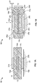
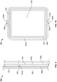
- FIG. 1A and 1B a schematic representation is provided of a surface deformation EAP actuator 10 for converting electrical energy to mechanical energy in accordance with one embodiment of the invention.
- Actuator 10 includes EAP transducer 12 having a thin elastomeric dielectric polymer layer 14 and top and bottom electrodes 16a, 16b attached to the dielectric 14 on portions of its top and bottom surfaces, respectively.
- the portion of transducer 12 comprising the dielectric and at least two electrodes is referred to herein as an active area. Any of the transducers of the present invention may have one or more active areas.
- this action causes the compliant dielectric material outside the active area (i.e., the area covered by the electrodes), particularly perimetrically about, i.e., immediately around, the edges of the active area, to be displaced or bulge out-of-plane in the thickness direction (orthogonal to the plane defined by the transducer film).
- This bulging produces dielectric surface features 24a-d. While out-of-plane surface features 24 are shown relatively local to the active area, the out-of-plane is not always localized as shown. In some cases, if the polymer is pre-strained, then the surface features 24a-b are distributed over a surface area of the inactive portion of the dielectric material.
- an optional passive layer may be added to one or both sides of the transducer film structure where the passive layer covers all or a portion of the EAP film surface area.
- top and bottom passive layers 18a, 18b are attached to the top and bottom sides, respectively, of the EAP film 12.
- Activation of the actuator and the resulting surface features 17a-d of dielectric layer 12 are amplified by the added thickness of passive layers 18a, 18b, as denoted by reference numbers 26a-d in Fig. 1B .
- the EAP film 12 may be configured such that the one or both electrodes 16a, 16b are depressed below the thickness of the dielectric layer. As such, the depressed electrode or portion thereof provides an electrode surface feature upon actuation of the EAP film 12 and the resulting deflection of dielectric material 14. Electrodes 16a, 16c may be patterned or designed to produce customized transducer film surface features which may comprise polymer surface features, electrode surface features and/or passive layer surface features.
- one or more structures 20a, 20b are provided to facilitate coupling the work between the compliant passive slab and a rigid mechanical structure and directing the work output of the actuator.
- top structure 20a (which may be in the form of a platform, bar, lever, rod, etc.) acts as an output member while bottom structure 20b serves to couple actuator 10 to a fixed or rigid structure 22, such as ground.
- These output structures need not be discrete components but, rather, may be integrated or monolithic with the structure which the actuator is intended to drive.
- Structures 20a, 20b also serve to define the perimeter or shape of the surface features 26a-d formed by the passive layers 18a, 18b.
- the collective actuator stack produces an increase in thickness of the actuator's inactive portions, as shown in Fig. 1B , the net change in height ⁇ h undergone by the actuator upon actuation is negative.
- the EAP transducers of the present invention may have any suitable construct to provide the desired thickness mode actuation.
- more than one EAP film layer may be used to fabricate the transducers for use in more complex applications, such as keyboard keys with integrated sensing capabilities where an additional EAP film layer may be employed as a capacitive sensor.
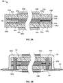
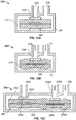
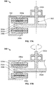
- Fig. 2A illustrates such an actuator 30 employing a stacked transducer 32 having a double EAP film layer 34 in accordance with the present invention.
- the double layer includes two dielectric elastomer films with the top film 34a sandwiched between top and bottom electrodes 34b, 34c, respectively, and the bottom film 36a sandwiched between top and bottom electrodes 36b, 36c, respectively.
- Pairs of conductive traces or layers are provided to couple the electrodes to the high voltage and ground sides of a source of power (the latter not shows).
- the bus bars are positioned on the "inactive'' portions of the respective EAP films (i.e., the portions in which the top and bottom electrodes do not overlap).
- Top and bottom bus bars 42a, 42b are positioned on the top and bottom sides, respectively, of dielectric layer 34a, and top and bottom bus bars 44a, 44b positioned on the top and bottom sides, respectively, of dielectric layer 36a.
- the top electrode 34b of dielectric 34a and the bottom electrode 36c of dielectric 36a i.e., the two outwardly facing electrodes, are commonly polarized by way of the mutual coupling of bus bars 42a and 44a through conductive elastomer via 68a (shown in Fig. 2B ), the formation of which is described in greater detail below with respect to Figs. 3A-3D .
- the bottom electrode 34c of dielectric 34a and the top electrode 36b of dielectric 36a are also commonly polarized by way of the mutual coupling of bus bars 42b and 44b through conductive elastomer via 68b (shown in Fig. 2B ). Potting material 66a, 66b is used to seal via 68a. 68b.
- the opposing electrodes of each electrode pair are drawn together when a voltage is applied.
- the ground electrodes may be placed on the outside of the stack so as to ground any piercing object before it reaches the high voltage electrodes, thus eliminating a shock hazard.
- the two EAP film layers may be adhered together by film-to-film adhesive 40b.
- the adhesive layer may optionally include a passive or slab layer to enhance performance.
- a top passive layer or slab 50a and a bottom passive layer 52b are adhered to the transducer structure by adhesive layer 40a and by adhesive layer 40c.
- Output bars 46a, 46b may be coupled to top and bottom passive layers, respectively, by adhesive layers 48a, 48b, respectfully.
- the actuators of the present invention may employ any suitable number of transducer layers, where the number of layers may be even or odd. In the latter construct, one or more common ground electrode and bus bar may be used. Additionally, where safety is less of an issue, the high voltage electrodes may be positioned on the outside of the transducer stack to better accommodate a particular application.
- actuator 30 must be electrically coupled to a source of power and control electronics (neither are shown). This may be accomplished by way of electrical tracing or wires on the actuator or on a PCB or a flex connector 62 which couples the high voltage and ground vias 68a, 68b to a power supply or an intermediate connection.
- Actuator 30 may be packaged in a protective barrier material to seal it from humidity and environmental contaminants.
- the protective barrier includes top and bottom covers 60, 64 which are preferably sealed about PCB/flex connector 62 to protect the actuator from external forces and strains and/or environmental exposure.
- the protective barrier maybe impermeable to provide a hermetic seal.
- the covers may have a somewhat rigid form to shield actuator 30 against physical damage or may be compliant to allow room for actuation displacement of the actuator 30.
- the top cover 60 is made of formed foil and the bottom cover 64 is made of a compliant foil, or vice versa, with the two covers then heat-sealed to board/connector 62.
- Many other packaging materials such as metalized polymer films, PVDC, Aclar, styrenic or olefinic copolymers, polyesters and polyolefins can also be used.
- Compliant material is used to cover the output structure or structures, here bar 46b, which translate actuator output.
- conductive components/layers of the stacked actuator/transducer structures of the present invention are commonly coupled by way of electrical vias (68a and 68b in Fig. 2B ) formed through the stacked structure.
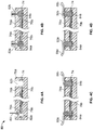
- Figs. 3-5 illustrate various methods of the present invention for forming the vias.
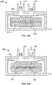
- Figs. 3A-3D Formation of the conductive vias of the type employed in actuator 30 of Fig. 2B is described with reference to Figs. 3A-3D .
- actuator 70 constructed from a single-film transducer with diametrically positioned bus bars 76a, 76b placed on opposite sides of the inactive portions of dielectric layer 74, collectively sandwiched between passive layers 78a, 78b
- the stacked transducer/actuator structure 70 is laser drilled 80 through its entire thickness to PCB 72 to form the via holes 82a, 82b, as illustrated in Fig. 3B .
- the via holes are then filled by any suitable dispensing method, such as by injection, with a conductive material, e.g., carbon particles in silicone, as shown in Fig. 3C .
- a conductive material e.g., carbon particles in silicone
- the conductively filled vias 84a, 84b are optionally potted 86a, 86b with any compatible non-conductive material, e.g.. silicone, to electrically isolate the exposed end of the vias.
- a non-conductive tape may be placed over the exposed vias.
- Standard electrical wiring may be used in lieu of a PCB or flex connector to couple the actuator to the power supply and electronics.
- Various steps of foaming the electrical vias and electrical connections to the power supply with such embodiments are illustrated in Figs. 4A-4D with like components and steps to those in Figs. 3A-3D having the same reference numbers.
- via holes 82a, 82b need only be drilled to a depth within the actuator thickness to the extent that the bus bars 84a, 84b are reached.
- the via holes are then filled with conductive material, as shown in Fig. 4B , after which wire leads 88a, 88b are inserted into the deposited conductive material, as shown in Fig. 4C .
- the conductively filled vias and wire leads may then be potted over, as shown in Fig. 4D .
- Transducer 100 has a dielectric film comprising a dielectric layer 104 having portions sandwiched between electrodes 106a, 106b, which in turn are sandwiched between passive polymer layers 110a, 110b.
- a conductive bus bar 108 is provided on an inactive area of the EAP film.
- a conductive contact 114 having a piercing configuration is driven, either manually or otherwise, through one side of the transducer to a depth that penetrates the bus bar material 108.
- a conductive trace 116 extends along PCB/flex connector 112 from the exposed end of piercing contact 114. This method of forming vias is particularly efficient as it eliminates the steps of drilling the via holes, filling the via holes, placing a conductive wire in the via holes and potting the via holes.
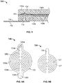
- the thickness mode EAP transducers of the present invention are usable in a variety of actuator applications with any suitable construct and surface feature presentation.
- Figs. 6-10 illustrate exemplary thickness mode transducer/actuator applications.
- Fig. 6A illustrates a thickness mode transducer 120 having a round construct which is ideal for button actuators for use in tactile or haptic feedback applications in which a user physically contacts a device, e.g., keyboards, touch screens, phones, etc.
- Transducer 120 is formed from a thin elastomeric dielectric polymer layer 122 and top and bottom electrode patterns 124a, 124b (the bottom electrode pattern is shown in phantom), best shown in the isolated view in Fig. 6B .
- Each of the electrode patterns 124 provides a stem portion 125 with a plurality of oppositely extending finger portions 127 forming a concentric pattern.
- the stems of the two electrodes are positioned diametrically to each other on opposite sides of the round dielectric layer 122 where their respective finger portions are in appositional alignment with each other to produce the pattern shown in Fig. 6A . While the opposing electrode patterns in this embodiment are identical and symmetrical to each other, other embodiments are contemplated where the opposing electrode patterns are asymmetric, in shape and/or the amount of surface area which they occupy.
- the portions of the transducer material in which the two electrode materials do not overlap define the inactive portions 128a, 128b of the transducer.
- An electrical contact 126a, 126b is provided at the base of each of the two electrode stem portions for electrically coupling the transducer to a source of power and control electronics (neither are shown).
- the transducer When the transducer is activated, the opposing electrode fingers are drawn together, thereby compressing dielectric material 122 therebetween with the inactive portions 128a, 128b of the transducer bulging to form surface features about the perimeter of the button and/or internally to the button as desired.
- the button actuator may be in the form of a single input or contact surface or may be provided in an array format having a plurality of contact surfaces.
- the button transducers of Fig. 6A are ideal for use in keypad actuators 130, as illustrated in Fig. 7 , for a variety of user interface devices, e.g., computer keyboards, phones, calculators, etc.
- Transducer array 132 includes a top array 136a of interconnected electrode patterns and bottom array 136b (shown in phantom) of electrode patterns with the two arrays opposed with each other to produce the concentric transducer pattern of Fig. 6A with active and inactive portions as described.
- the keyboard structure may be in the form of a passive layer 134 atop transducer array 132.
- Passive layer 134 may have its own surface features, such as key border 138, which may be raised in the passive state to enable the user to tactilely align his/her fingers with the individual key pads, and/or further amplify the bulging of the perimeter of the respective buttons upon activation.
- key border 138 When a key is pressed, the individual transducer upon which it lays is activated, causing the thickness mode bulging as described above, to provide the tactile sensation back to the user.
- Any number of transducers may be provided in this manner and spaced apart to accommodate the type and size of keypad 134 being used. Examples of fabrication techniques for such transducer arrays are disclosed in U.S. Patent Application No. 12/163,554 filed on June 27, 2008 entitled ELECTROACTIVE POLYMER TRANSDUCERS FOR SENSORY FEEDBACK APPLICATIONS.
- the thickness mode transducers of the present invention need not be symmetrical and may take on any construct and shape.
- the subject transducers may be used in any imaginable novelty application, such as the novelty hand device 140 illustrated in Fig. 8 .
- Dielectric material 142 in the form of a human hand is provided having top and bottom electrode patterns 144a, 144b (the underside pattern being shown in phantom) in a similar hand shape.
- Each of the electrode patterns is electrically coupled to a bus bar 146a, 146b, respectively, which in turn is electrically coupled to a source of power and control electronics (neither are shown).
- the opposing electrode patterns are aligned with or atop each other rather than interposed, thereby creating alternating active and inactive areas.
- raised surface features are provided throughout the hand profile, i.e., on the inactive areas.
- the surface features in this exemplary application may offer a visual feedback rather than a tactile feedback. It is contemplated that the visual feedback may be enhanced by coloring, reflective material, etc.
- the transducer film of the present invention may be efficiently mass produced, particularly where the transducer electrode pattern is uniform or repeating, by commonly used web-based manufacturing techniques.
- the transducer film 150 may be provided in a continuous strip format having continuous top and bottom electrical buses 156a, 156b deposited or formed on a strip of dielectric material 152.
- the thickness mode features are defined by discrete (i.e., not continuous) but repeating active regions 158 formed by top and bottom electrode patterns 154a, 154b electrically coupled to the respective bus bars 156a, 156b; the size, length, shape and pattern of which may be customized for the particular application.
- the active region(s) may be provided in a continuous pattern.
- the electrode and bus patterns may be formed by known web-based manufacturing techniques, with the individual transducers then singulated, also by known techniques such as by cutting strip 150 along selected singulation lines 155. It is noted that where the active regions are provided continuously along the strip, the strip is required to be cut with a high degree of precision to avoid shooting the electrodes. The cut ends of these electrodes may require potting or otherwise may be etched back to avoid tracking problems. The cut terminals of buses 156a, 156b are then coupled to sources of power/control to enable actuation of the resulting actuators.
- the strip or singulated strip portions may be stacked with any number of other transducer film strips/strip portions to provide a multi-layer structure.
- the stacked structure may then be laminated and mechanically coupled, if so desired, to rigid mechanical components of the actuator, such an output bar or the like.
- Fig. 10 illustrates another variation of the subject transducers in which a transducer 160 formed by a strip of dielectric material 162 with top and bottom electrodes 164a, 164b on opposing sides of the strip arranged in a rectangular pattern thereby framing an open area 165.
- Each of the electrodes terminates in an electrical bus 166a., 166b, respectively, having an electrical contact point 168a, 168b for coupling to a source of power and control electronics (neither being shown).
- a passive layer (not shown) that extends across the enclosed area 165 may be employed on either side of the transducer film, thereby forming a gasket configuration, for both environmental protection and mechanical coupling of the output bars (also not shown).
- gasket actuator need not be a continuous, single actuator.
- One or more discrete actuators can also be used to line the perimeter of an area which may be optionally sealed with non-active compliant gasket material
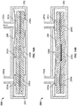
- Figs. 11A-11D are cross-sectional views of touch screens employing variations of a thickness mode actuator of the present invention with like reference numbers referencing similar components amongst the four figures.
- the touch screen device 170 may include a touch sensor plate 174, typically made of a glass or plastic material, and, optionally, a liquid crystal display (LCD) 172.
- the two are stacked together and spaced apart by EAP thickness mode actuator 180 defining an open space 176 therebetween.
- the collective stacked structure is held together by frame 178.
- Actuator 180 includes the transducer film formed by dielectric film layer 182 sandwiched centrally by electrode pair 184a, 184b.
- the transducer film is in turn sandwiched between top and bottom passive layers 186a, 186b and further held between a pair of output structures 188a, 188b which are mechanically coupled to touch plate 174 and LCD 172, respectively.
- the right side of Fig. 11A shows the relative position of the LCD and touch plate when the actuator is inactive, while the left side of Fig. 11A shows the relative positions of the components when the actuator is active, i.e., upon a user depressing touch plate 174 in the direction of arrow 175.
- the electrodes 184a, 184b are drawn together thereby compressing the portion of dielectric film 182 therebetween while creating surface features in the dielectric material and passive layers 186a, 186b outside the active area, which surface features are further enhanced by the compressive force caused by output blocks 188a, 188b.
- the surface features provide a slight force on touch plate 174 in the direction opposite arrow 175 which gives the user a tactile sensation in response to depressing the touch plate.
- Touch screen device 190 of Fig. 11B has a similar construct to that of Fig. 11A with the difference being that LCD 172 wholly resides within the internal area framed by the rectangular (or square, etc.) shaped thickness mode actuator 180.
- the spacing 176 between LCD 172 and touch plate 174 when the device is in an inactive state is significantly less than in the embodiment of Fig. 11A , thereby providing a lower profile design.
- the bottom output structure 188b of the actuator rests directly on the back wall 178' of frame 178.
- device 190 functions similarly to device 170 in that the actuator surface features provide a slight tactile force in the direction opposite arrow 185 in response to depressing the touch plate.
- the two touch screen devices just described are single phase devices as they function in a single direction.
- Two (or more) of the subject gasket-type actuators may be used in tandem to produce a two phase (bi-directional) touch screen device 200 as in Fig. 11C .
- the construct of device 200 is similar to that of the device of Fig. 11B but with the addition of a second thickness mode actuator 180' which sits atop touch plate 174.
- the two actuators and touch plate 174 are held in stacked relation by way of frame 178 which has an added inwardly extending top shoulder 178".
- touch plate 174 is sandwiched directly between the innermost output blocks 188a, 188b' of actuators 180, 180', respectively, while the outermost output blocks 188b, 188a' of actuators 180', respectively, buttress the frame members 178' and 178", respectively.
- This enclosed gasket arrangement keeps dust and debris out of the optical path within space 176.
- the left side of the figure illustrates bottom actuator 180 in an active state and top actuator 180' in a passive state in which sensor plate 174 is caused to move towards LCD 172 in the direction of arrow 195.
- the right side of the figure illustrates bottom actuator 180 in a passive state and top actuator 180' in an active state in which sensor plate 174 is caused to move away from LCD 172 in the direction of arrow 195'.
- Fig. 11D illustrates another two phase touch sensor device 210 but with a pair of thickness mode strip actuators 180 oriented with the electrodes orthogonal to the touch sensor plate.
- the two phase or by-directional movement of touch plate 174 is in-plane as indicated by arrow 205.
- the actuator 180 is positioned such that the plane of its EAP film is orthogonal to those of LCD 172 and touch plate 174.
- actuator 180 is held between the sidewall 202 of frame 178 and an inner frame member 206 upon which rests touch plate 174.
- inner frame member 206 While inner frame member 206 is affixed to the output block 188a of actuator 180, it and touch plate 174 are "floating" relative to outer frame 178 to allow for the in-plane or lateral motion.
- This construct provides a relatively compact, low-profile design as it eliminates the added clearance that would otherwise be necessary for two-phase out-of-plane motion by touch plate 174.
- the two actuators work in opposition for two-phase motion.
- the combined assembly of plate 174 and brackets 206 keep the actuator strips 180 in slight compression against the sidewall 202 of frame 178. When one actuator is active, it compresses or thins further while the other actuator expands due to the stored compressive force. This moves the plate assembly toward the active actuator. The plate moves in the opposite direction by deactivating the first actuator and activating the second actuator.
- Figs. 12A and 12B show a one-way poppet valve mechanism 220 employing thickness mode actuator 232.
- the actuator is seated within fluid chamber 234 having fluid inlet and outlet ports 236, 238, respectively.
- Actuator 232 is situation within chamber 234 such that its output structure 240 is aligned with outlet port 238.
- output structure 240 is buttressed against aperture 238' of the outlet port which defines the valve seat.
- the valves has a normally closed configuration.
- the thickness mode operation of the actuator 232 when activated pulls output structure 240 away from valve seat 238' thereby allowing fluid within chamber 234 to exit through outlet port 238.
- Fig. 12C illustrates a two-way poppet valve 250 having fluid chamber 254 with an inlet port 256 and two output ports 258a, 258b having respective apertures 258a', 258b'.
- An actuator mechanism 252 contained within the chamber includes two activatable portions 252a, 252b, each having an output structure 260a, 260b, respectively, aligned with output ports 258a, 258b, respectively.
- actuator portion 252a is active while actuator portion 252b is inactive, thereby alternating fluid flow through the two outlet ports.
- both actuator portions may be activated in tandem, if desired.
- valve 250 may have any number of outlet port-actuator pairings with actuation function being accomplished with either a monolithic structure with a plurality of activatable portions, as illustrated, or a plurality of structurally discrete actuators.
- the individual actuators or actuator portions may be activated in tandem or independently, such that any combination of output flow is provided.
- the subject actuators are also suitable for use with diaphragm type pumps.
- One such diaphragm pump 270 is shown in Figs. 13A and 13B in which the fluid chamber 274 has inlet and outlet ports 276, 278, respectively. having check valves mechanisms to control fluid flow therethrough.
- the output structure 280 of thickness mode actuator 272 is affixed to the underside of a diaphragm 282 that extends between the sidewalls and across the upper end of chamber 274.
- the diaphragm is made of a material stiff enough to not flex or stretch under compression pressure, e.g., fiber reinforced rubbers, stiff elastomers, filled silicone, a thin metal membrane, etc.
- Activating and deactivating actuator 272 moves diaphragm 282 away and towards, respectively, the inlet and outlet ports.
- outlet check valve 278 With the positive pressure created in chamber 274 when diaphragm 274 is moved towards the ports, as illustrated in Fig. 13A , outlet check valve 278 is caused to open allow fluid to be exhausted from the chamber. Conversely, with the negative pressure created in chamber 274 when diaphragm 274 is moved away franc the ports, as illustrated in Fig. 13B , inlet check valve 278 is caused to open, creating fluid intake to the chamber.
- Figs. 14A and 14B illustrate another diaphragm-type pump employing thickness mode a multi-actuator mechanism 276.
- the actuator has three activatable portions 276a-c (but may have more or fewer portions), with the outer two portions 276a, 276c being aligned relative to inlet-outlet ports 274a, 274b, respectively, of fluid chamber 292.
- Diaphragm 298 is coupled at its underside to the respective output structures 300a-c of the actuator portions.
- To exhaust fluid from chamber 292, one or both ports 294a, 294b are opened, as illustrated in Fig. 14A , by activating outer actuators 296a, 296c.
- deactivating the outer actuators while activating the center actuator 296b. as illustrated in Fig. 14B , closes both valve ports while also priming the pump for the next exhaust stroke.
- Diaphragm sheet 298 may employ multiple materials so as to facilitate the poppet valve sealing, for example, the membrane could be made of a metal foil
- Pump 310 comprises a chamber or conduit (which may have any suitable cross-sectional shape, e.g., cylindrical, rectangular, square, etc.) having a base 312a and a top portion or cover 312b.
- Thickness mode actuator mechanism 318 here having four activatable portions illustrated, is offset from base 312a by output or mounting structures 314a.
- the opposing output structures 314b are coupled to the underside of diaphragm 316.
- the spacing provided by the offset of the structures 314a, 31b allow for the thickness mode bulging of the inactive portions and the compressing of the active portions of the actuator strip 318. Fluid is caused to linearly move between diaphragm 316 and top cover 312b by sequential activation and deactivation of the various active portions of actuator 318. The flow rate may be varied by controlling the on-off rate of the active portions.
- a fixed diaphragm 322 may be mounted to the underside of top cover 312b to facilitate fluid flow dynamics through the passageway 320 defined between the two diaphragms or to provide a disposable fluid path (with the actuator and housing being non-disposable).
- Fig. 15B illustrates another peristaltic pump 330 with a simplified design in that the diaphragm(s) and top output structures of the peristaltic pump of Fig. 15A have been eliminated.
- the top passive layer 324 of actuator 318 takes the function of previous diaphragm 316, with fluid passing through the spacing 326 between the passive layer and the top cover or 312b.
- Figs 16A and 16B illustrate a proportional linear braking system 330 in which a moveable member 332 (such as those used for commonly known rod bearing arrangement) is linearly translatable within the spacing between a grounded structure 338 and a brake mechanism 334.
- the brake includes thickness mode actuator mechanism 336 positioned within housing 334, which is also grounded.
- Actuator 336 may have one or more active areas (i.e., two active areas are employed here) depending on the surface area of member 332 and the breaking force required to stop its movement. For maximum breaking force (as well as for maximum clearance), all of the active areas are activated/deactivated simultaneously. In the passive state, as illustrated in Fig.
- the output plate 342 of the actuators is in a closed or extended position, thereby clamping member 332 against grounding pad 338.
- output plate 342 is open or receded within housing 334, providing clearance for the linear movement of member 332.
- Figs 17A and 17B illustrate a rotary braking system 350 having a rotary disc 352 having a disc element 352a and an axial shaft 352b.
- the braking actuators 356a, 356b are mounted in stacked relationship within a housing 354.
- Disc 352 is positioned within the spacing between inwardly facing output members or braking or clutch pads 358a, 35b, respectively.
- actuators 356a, 356b are inactive and in their highest profile, as illustrated in Fig. 17A , they are caused to clamp down and stop the rotation of disc 352.
- disc 352 When the actuators are active and in a compressed state, disc 352 is undamped and allowed to move therethrough.
- the amount of braking force applied to disc 352a can be proportioned by either activating one of the two actuators or activating them both in tandem but at a decreased voltage to reduce their respective output displacement.
- the transducer/actuator embodiments described thus far have the passive layer(s) coupled to both the active (i.e., areas including overlapping electrodes) and inactive regions of the EAP transducer film.
- the transducer/actuator has also employed a rigid output structure, that structure has been positioned over areas of the passive layers that reside above the active regions.
- the active/activatable regions of these embodiments have been positioned centrally relative to the inactive regions.
- the present invention also includes other transducer/actuator configurations.
- the passive layer(s) may cover only the active regions or only the inactive regions.
- the inactive regions of the EAP film may be positioned centrally to the active regions.
- Figs. 18A and 18B illustrate one such variation in which the inactive area is positioned internally or centrally to the active region(s), i.e., the central portion of the EAP film is devoid of overlapping electrodes.
- Thickness mode actuator 360 includes EAP transducer film comprising dielectric layer 362 sandwiched between electrode layers 364a, 354b in which a central portion 365 of the film is passive and devoid of electrode material.
- the EAP film is held in a taut or stretched condition by at least one of top and bottom frame members 366a, 366b, collectively providing a cartridge configuration.
- the passively coupled film actuators may be provided in multiples in stacked or planar relationships to provide multi-phase actuation and/or to increase the output force and/or stroke of the actuator.
- the actuator may be used as a key or button device and may be stacked or integrated with sensor devices such as membrane switches.
- the bottom output member or bottom electrode can be used to to provide sufficient pressure to a membrane switch to complete the circuit or can complete the circuit directly if the bottom output member has a conductive layer. Multiple actuators can be used in arrays for applications such as keypads or keyboards.
- the various dielectric elastomer and electrode materials disclosed in U.S. Patent Application Publication No. 2005/0157893 are suitable for use with the thickness mode transducers of the present invention.
- the dielectric elastomers include any substantially insulating, compliant polymer, such as silicone rubber and acrylic, that deforms in response to an electrostatic force or whose deformation results in a change in electric field.
- the optimal material, physical, and chemical properties can be tailored by judicious selection of monomer (including any side chains), additives, degree of crosslinking, crystallinity, molecular weight, etc.
- Electrodes described therein and suitable for use include structured electrodes comprising metal traces and charge distribution layers, textured electrodes, conductive greases such as carbon greases or silver greases, colloidal suspensions, high aspect ratio conductive materials such as conductive carbon black, carbon fibrils, carbon nanotubes, graphene and metal nanowires, and mixtures of ionically conductive materials.
- the electrodes may be made of a compliant material such as elastomer matrix containing carbon or other conductive particles.
- the present invention may also employ metal and semi-inflexible electrodes.
- Exemplary passive layer materials for use in the subject transducers include but are not limited to silicone, styrenic or olefinic copolymer, polyurethane, acrylate, rubber, a soft polymer, a soft elastomer (gel), soft polymer foam, or a polymer/gel hybrid, for example.
- the relative elasticity and thickness of the passive layer(s) and dielectric layer are selected to achieve a desired output (e.g., the net thickness or thinness of the intended surface features), where that output response may be designed to be linear (e.g., the passive layer thickness is amplified proportionally to the that of the dielectric layer when activated) or non-linear (e.g., the passive and dielectric layers get thinner or thicker at varying rates).
- the subject methods may include each of the mechanical and/or activities associated with use of the devices described. As such, methodology implicit to the use of the devices described forms part of the invention. Other methods may focus on fabrication of such devices.
Landscapes
- Engineering & Computer Science (AREA)
- General Engineering & Computer Science (AREA)
- Theoretical Computer Science (AREA)
- Physics & Mathematics (AREA)
- Human Computer Interaction (AREA)
- General Physics & Mathematics (AREA)
- Manufacturing & Machinery (AREA)
- Spectroscopy & Molecular Physics (AREA)
- General Electrical Machinery Utilizing Piezoelectricity, Electrostriction Or Magnetostriction (AREA)
- Push-Button Switches (AREA)
- Position Input By Displaying (AREA)
- Laminated Bodies (AREA)
- Micromachines (AREA)
Applications Claiming Priority (3)
| Application Number | Priority Date | Filing Date | Title |
|---|---|---|---|
| US11164808P | 2008-11-05 | 2008-11-05 | |
| US12/358,142 US8222799B2 (en) | 2008-11-05 | 2009-01-22 | Surface deformation electroactive polymer transducers |
| PCT/US2009/063441 WO2010054115A1 (en) | 2008-11-05 | 2009-11-05 | Surface deformation electroactive polymer transducers |
Publications (3)
| Publication Number | Publication Date |
|---|---|
| EP2347459A1 EP2347459A1 (en) | 2011-07-27 |
| EP2347459A4 EP2347459A4 (en) | 2014-11-19 |
| EP2347459B1 true EP2347459B1 (en) | 2017-08-23 |
Family
ID=42130526
Family Applications (1)
| Application Number | Title | Priority Date | Filing Date |
|---|---|---|---|
| EP09825433.7A Active EP2347459B1 (en) | 2008-11-05 | 2009-11-05 | Surface deformation electroactive polymer transducers |
Country Status (9)
| Country | Link |
|---|---|
| US (1) | US8222799B2 (enExample) |
| EP (1) | EP2347459B1 (enExample) |
| JP (1) | JP5684713B2 (enExample) |
| KR (2) | KR20110097764A (enExample) |
| CN (1) | CN102272959A (enExample) |
| CA (1) | CA2742410A1 (enExample) |
| MX (1) | MX2011004695A (enExample) |
| TW (1) | TWI527070B (enExample) |
| WO (1) | WO2010054115A1 (enExample) |
Families Citing this family (184)
| Publication number | Priority date | Publication date | Assignee | Title |
|---|---|---|---|---|
| WO2009006318A1 (en) | 2007-06-29 | 2009-01-08 | Artificial Muscle, Inc. | Electroactive polymer transducers for sensory feedback applications |
| US9370640B2 (en) | 2007-09-12 | 2016-06-21 | Novasentis, Inc. | Steerable medical guide wire device |
| US8570295B2 (en) | 2008-01-04 | 2013-10-29 | Tactus Technology, Inc. | User interface system |
| US8922510B2 (en) | 2008-01-04 | 2014-12-30 | Tactus Technology, Inc. | User interface system |
| US9372565B2 (en) | 2008-01-04 | 2016-06-21 | Tactus Technology, Inc. | Dynamic tactile interface |
| US8970403B2 (en) | 2008-01-04 | 2015-03-03 | Tactus Technology, Inc. | Method for actuating a tactile interface layer |
| US9274612B2 (en) | 2008-01-04 | 2016-03-01 | Tactus Technology, Inc. | User interface system |
| US9557915B2 (en) | 2008-01-04 | 2017-01-31 | Tactus Technology, Inc. | Dynamic tactile interface |
| US20160187981A1 (en) | 2008-01-04 | 2016-06-30 | Tactus Technology, Inc. | Manual fluid actuator |
| US8547339B2 (en) | 2008-01-04 | 2013-10-01 | Tactus Technology, Inc. | System and methods for raised touch screens |
| US8553005B2 (en) | 2008-01-04 | 2013-10-08 | Tactus Technology, Inc. | User interface system |
| US9612659B2 (en) | 2008-01-04 | 2017-04-04 | Tactus Technology, Inc. | User interface system |
| US8243038B2 (en) | 2009-07-03 | 2012-08-14 | Tactus Technologies | Method for adjusting the user interface of a device |
| US9280224B2 (en) | 2012-09-24 | 2016-03-08 | Tactus Technology, Inc. | Dynamic tactile interface and methods |
| US9298261B2 (en) | 2008-01-04 | 2016-03-29 | Tactus Technology, Inc. | Method for actuating a tactile interface layer |
| US9052790B2 (en) | 2008-01-04 | 2015-06-09 | Tactus Technology, Inc. | User interface and methods |
| US9367132B2 (en) | 2008-01-04 | 2016-06-14 | Tactus Technology, Inc. | User interface system |
| US9063627B2 (en) | 2008-01-04 | 2015-06-23 | Tactus Technology, Inc. | User interface and methods |
| US9720501B2 (en) | 2008-01-04 | 2017-08-01 | Tactus Technology, Inc. | Dynamic tactile interface |
| US9128525B2 (en) | 2008-01-04 | 2015-09-08 | Tactus Technology, Inc. | Dynamic tactile interface |
| US9588683B2 (en) | 2008-01-04 | 2017-03-07 | Tactus Technology, Inc. | Dynamic tactile interface |
| US8456438B2 (en) | 2008-01-04 | 2013-06-04 | Tactus Technology, Inc. | User interface system |
| US8947383B2 (en) | 2008-01-04 | 2015-02-03 | Tactus Technology, Inc. | User interface system and method |
| US9552065B2 (en) | 2008-01-04 | 2017-01-24 | Tactus Technology, Inc. | Dynamic tactile interface |
| US8154527B2 (en) | 2008-01-04 | 2012-04-10 | Tactus Technology | User interface system |
| US9423875B2 (en) | 2008-01-04 | 2016-08-23 | Tactus Technology, Inc. | Dynamic tactile interface with exhibiting optical dispersion characteristics |
| US9588684B2 (en) | 2009-01-05 | 2017-03-07 | Tactus Technology, Inc. | Tactile interface for a computing device |
| US8760413B2 (en) | 2009-01-08 | 2014-06-24 | Synaptics Incorporated | Tactile surface |
| EP2239793A1 (de) | 2009-04-11 | 2010-10-13 | Bayer MaterialScience AG | Elektrisch schaltbarer Polymerfilmaufbau und dessen Verwendung |
| US8915151B2 (en) * | 2009-06-05 | 2014-12-23 | Sungkyunkwan University Foundation For Corporate Collaboration | Active skin for conformable tactile interface |
| CN101923417B (zh) * | 2009-06-10 | 2013-06-05 | 鸿富锦精密工业(深圳)有限公司 | 触控式输入装置 |
| JP2012532384A (ja) | 2009-07-03 | 2012-12-13 | タクタス テクノロジー | ユーザインターフェイス拡張システム |
| US10164135B2 (en) * | 2009-08-07 | 2018-12-25 | Guardian Glass, LLC | Electronic device including graphene-based layer(s), and/or method or making the same |
| US8569935B1 (en) * | 2009-09-14 | 2013-10-29 | Tomasz Andrzej Kosierkiewicz | Piezoelectric shoe insert |
| US8624839B2 (en) | 2009-10-15 | 2014-01-07 | Synaptics Incorporated | Support-surface apparatus to impart tactile feedback |
| US10068728B2 (en) | 2009-10-15 | 2018-09-04 | Synaptics Incorporated | Touchpad with capacitive force sensing |
| KR101113897B1 (ko) | 2009-12-07 | 2012-02-29 | 한국과학기술원 | 나선형의 투명전극을 이용한 전자기력발생 시스템, 이를 이용한 햅틱제공장치, 이를 이용한 터치패드 및 그 제어방법 |
| CN102782617B (zh) | 2009-12-21 | 2015-10-07 | 泰克图斯科技公司 | 用户接口系统 |
| CN102725716B (zh) | 2009-12-21 | 2016-04-13 | 泰克图斯科技公司 | 用户界面系统 |
| US9239623B2 (en) | 2010-01-05 | 2016-01-19 | Tactus Technology, Inc. | Dynamic tactile interface |
| US8619035B2 (en) | 2010-02-10 | 2013-12-31 | Tactus Technology, Inc. | Method for assisting user input to a device |
| KR20130016288A (ko) | 2010-03-17 | 2013-02-14 | 바이엘 인텔렉쳐 프로퍼티 게엠베하 | 인지가능한 피드백 발생을 위한 오디오 신호의 통계적 분석 |
| US20110242041A1 (en) * | 2010-04-01 | 2011-10-06 | Nokia Corporation | Method and Apparatus for Performing a Function |
| WO2011133604A1 (en) | 2010-04-19 | 2011-10-27 | Tactus Technology | User interface system |
| WO2012032443A1 (en) * | 2010-09-09 | 2012-03-15 | Koninklijke Philips Electronics N.V. | Electroactive polymer actuator |
| US20120068938A1 (en) * | 2010-09-16 | 2012-03-22 | Research In Motion Limited | Electronic device with touch-sensitive display |
| DE102010042690A1 (de) * | 2010-10-20 | 2012-04-26 | Bayerische Motoren Werke Aktiengesellschaft | Eingabevorrichtung zur Steuerung eines elektronischen Geräts |
| WO2012054781A1 (en) | 2010-10-20 | 2012-04-26 | Tactus Technology | User interface system and method |
| EP2630562A1 (en) | 2010-10-20 | 2013-08-28 | Tactus Technology | User interface system |
| US8704647B2 (en) * | 2010-12-21 | 2014-04-22 | Electronics And Telecommunications Research Institute | Haptic feedback case for electronic equipment |
| JP5814774B2 (ja) * | 2010-12-22 | 2015-11-17 | 日本碍子株式会社 | 複合基板及び複合基板の製造方法 |
| DE102010056562B4 (de) | 2010-12-30 | 2018-10-11 | Snaptrack, Inc. | Elektroakustisches Bauelement und Verfahren zur Herstellung des elektroakustischen Bauelements |
| DE102010056572B4 (de) * | 2010-12-30 | 2018-12-27 | Snaptrack, Inc. | Elektronisches Bauelement und Verfahren zur Herstellung des elektronischen Bauelements |
| US8847890B2 (en) | 2011-01-04 | 2014-09-30 | Synaptics Incorporated | Leveled touchsurface with planar translational responsiveness to vertical travel |
| US8912458B2 (en) | 2011-01-04 | 2014-12-16 | Synaptics Incorporated | Touchsurface with level and planar translational travel responsiveness |
| JP2014513510A (ja) | 2011-03-01 | 2014-05-29 | バイエル・インテレクチュアル・プロパティ・ゲゼルシャフト・ミット・ベシュレンクテル・ハフツング | 変形可能なポリマー装置及び変形可能なポリマーフィルムを作るための自動化された製造プロセス |
| US9195058B2 (en) | 2011-03-22 | 2015-11-24 | Parker-Hannifin Corporation | Electroactive polymer actuator lenticular system |
| US10108288B2 (en) | 2011-05-10 | 2018-10-23 | Northwestern University | Touch interface device and method for applying controllable shear forces to a human appendage |
| US9122325B2 (en) | 2011-05-10 | 2015-09-01 | Northwestern University | Touch interface device and method for applying controllable shear forces to a human appendage |
| US10007341B2 (en) | 2011-06-21 | 2018-06-26 | Northwestern University | Touch interface device and method for applying lateral forces on a human appendage |
| US8866774B2 (en) * | 2011-06-29 | 2014-10-21 | The Board Of Trustees Of The Leland Stanford Junior University | Low power touch screen overlays for providing tactile feedback |
| WO2013017143A1 (en) * | 2011-08-04 | 2013-02-07 | L&P Swiss Holding Ag | Diaphragm pump for a seat adjusting device and seat adjusting device |
| TW201342788A (zh) * | 2011-12-09 | 2013-10-16 | Bayer Materialscience Ag | 製造致動器元件之技術 |
| US9220635B2 (en) | 2011-12-22 | 2015-12-29 | Douglas D. Churovich | Tactile pattern music generator and player |
| WO2013142552A1 (en) | 2012-03-21 | 2013-09-26 | Bayer Materialscience Ag | Roll-to-roll manufacturing processes for producing self-healing electroactive polymer devices |
| WO2013154720A1 (en) | 2012-04-13 | 2013-10-17 | Tk Holdings Inc. | Pressure sensor including a pressure sensitive material for use with control systems and methods of using the same |
| US9761790B2 (en) | 2012-06-18 | 2017-09-12 | Parker-Hannifin Corporation | Stretch frame for stretching process |
| US9705068B2 (en) | 2012-06-19 | 2017-07-11 | Novasentis, Inc. | Ultra-thin inertial actuator |
| US9183710B2 (en) | 2012-08-03 | 2015-11-10 | Novasentis, Inc. | Localized multimodal electromechanical polymer transducers |
| US9218927B2 (en) | 2012-08-06 | 2015-12-22 | Synaptics Incorporated | Touchsurface assembly with level and planar translational responsiveness via a buckling elastic component |
| US9040851B2 (en) | 2012-08-06 | 2015-05-26 | Synaptics Incorporated | Keycap assembly with an interactive spring mechanism |
| US9177733B2 (en) | 2012-08-06 | 2015-11-03 | Synaptics Incorporated | Touchsurface assemblies with linkages |
| US9324515B2 (en) | 2012-08-06 | 2016-04-26 | Synaptics Incorporated | Touchsurface assembly utilizing magnetically enabled hinge |
| EP2885868A4 (en) * | 2012-08-16 | 2016-04-13 | Bayer Ip Gmbh | LAMINATED AND COMPLIANT DIELECTRIC ELASTOMER ACTUATORS |
| KR20150077413A (ko) | 2012-09-17 | 2015-07-07 | 프레지던트 앤드 펠로우즈 오브 하바드 칼리지 | 인간의 움직임에 대한 보조를 위한 소프트 엑소슈트 |
| DE112013004512T5 (de) * | 2012-09-17 | 2015-06-03 | Tk Holdings Inc. | Einzelschicht-Kraftsensor |
| US9405417B2 (en) | 2012-09-24 | 2016-08-02 | Tactus Technology, Inc. | Dynamic tactile interface and methods |
| US9590193B2 (en) | 2012-10-24 | 2017-03-07 | Parker-Hannifin Corporation | Polymer diode |
| EP2917945B1 (en) * | 2012-11-06 | 2019-01-09 | Parker-Hannifin Corporation | Stacked electroactive transducer and fabrication method thereof |
| US9357312B2 (en) | 2012-11-21 | 2016-05-31 | Novasentis, Inc. | System of audio speakers implemented using EMP actuators |
| US9269885B2 (en) | 2012-11-21 | 2016-02-23 | Novasentis, Inc. | Method and localized haptic response system provided on an interior-facing surface of a housing of an electronic device |
| US9164586B2 (en) * | 2012-11-21 | 2015-10-20 | Novasentis, Inc. | Haptic system with localized response |
| US9053617B2 (en) | 2012-11-21 | 2015-06-09 | Novasentis, Inc. | Systems including electromechanical polymer sensors and actuators |
| CN104969080B (zh) * | 2012-11-21 | 2019-02-15 | 康拉德有限责任公司 | 用于测试工件的方法及装置 |
| US9170650B2 (en) | 2012-11-21 | 2015-10-27 | Novasentis, Inc. | EMP actuators for deformable surface and keyboard application |
| EP2929574A2 (en) | 2012-12-07 | 2015-10-14 | Bayer Materialscience AG | Electroactive polymer actuated aperture |
| WO2014097119A2 (en) * | 2012-12-18 | 2014-06-26 | Koninklijke Philips N.V. | Eap-driven airpump for patient interfaces |
| US10088936B2 (en) | 2013-01-07 | 2018-10-02 | Novasentis, Inc. | Thin profile user interface device and method providing localized haptic response |
| US9913321B2 (en) * | 2013-01-25 | 2018-03-06 | Energyield, Llc | Energy harvesting container |
| WO2014117125A1 (en) | 2013-01-28 | 2014-07-31 | Bayer Materialscience Llc | Electroactive polymer actuators and feedback system therefor |
| CN104049787B (zh) | 2013-03-14 | 2017-03-29 | 联想(北京)有限公司 | 一种电子设备和控制方法 |
| US9384919B2 (en) | 2013-03-14 | 2016-07-05 | Synaptics Incorporated | Touchsurface assembly having key guides formed in a sheet metal component |
| EP2971794A2 (en) | 2013-03-15 | 2016-01-20 | Covestro Deutschland AG | Electroactive polymer actuated air flow thermal management module |
| WO2014160757A2 (en) | 2013-03-26 | 2014-10-02 | Bayer Materialscience Ag | Independent tunig of audio devices employing electroactive polymer actuators |
| US9213372B2 (en) | 2013-04-19 | 2015-12-15 | Synaptics Incorporated | Retractable keyboard keys |
| CN105452992B (zh) | 2013-05-30 | 2019-03-08 | Tk控股公司 | 多维触控板 |
| CA2911275A1 (en) | 2013-05-31 | 2014-12-04 | President And Fellows Of Harvard College | Soft exosuit for assistance with human motion |
| US9557813B2 (en) | 2013-06-28 | 2017-01-31 | Tactus Technology, Inc. | Method for reducing perceived optical distortion |
| US10125758B2 (en) | 2013-08-30 | 2018-11-13 | Novasentis, Inc. | Electromechanical polymer pumps |
| US9833596B2 (en) | 2013-08-30 | 2017-12-05 | Novasentis, Inc. | Catheter having a steerable tip |
| US9507468B2 (en) | 2013-08-30 | 2016-11-29 | Novasentis, Inc. | Electromechanical polymer-based sensor |
| US10180723B2 (en) | 2013-10-08 | 2019-01-15 | Joyson Safety Systems Acquisition Llc | Force sensor with haptic feedback |
| US9666391B2 (en) | 2013-10-22 | 2017-05-30 | Novasentis, Inc. | Retractable snap domes |
| CA2932883A1 (en) | 2013-12-09 | 2015-06-18 | President And Fellows Of Harvard College | Assistive flexible suits, flexible suit systems, and methods for making and control thereof to assist human mobility |
| WO2015120186A1 (en) | 2014-02-05 | 2015-08-13 | President And Fellows Of Harvard College | Systems, methods, and devices for assisting walking for developmentally-delayed toddlers |
| EP3108510B1 (en) * | 2014-02-18 | 2018-12-26 | Parker Hannifin Corp | ELECTROACTIVE POLYMER ACTUATOR WITH IMPROVED PERFORMANCE |
| CN104916773B (zh) * | 2014-03-14 | 2017-10-20 | 中国科学院苏州纳米技术与纳米仿生研究所 | 电致变形薄膜阵列、其制备方法及应用 |
| US10864100B2 (en) | 2014-04-10 | 2020-12-15 | President And Fellows Of Harvard College | Orthopedic device including protruding members |
| DE102014005851B4 (de) * | 2014-04-22 | 2018-10-18 | Festo Ag & Co. Kg | Verfahren und Vorrichtung zur Herstellung von Elastomer-Aktuatoren |
| US9652946B2 (en) | 2014-05-02 | 2017-05-16 | Novasentis, Inc. | Hands-free, wearable vibration devices and method |
| US9576446B2 (en) | 2014-08-07 | 2017-02-21 | Novasentis, Inc. | Ultra-thin haptic switch with lighting |
| US9972768B2 (en) | 2014-08-15 | 2018-05-15 | Novasentis, Inc. | Actuator structure and method |
| KR20160031715A (ko) * | 2014-09-15 | 2016-03-23 | 삼성전자주식회사 | 기류 가변이 가능한 전면 송풍방식 공기조화장치 |
| CN106795868B (zh) | 2014-09-19 | 2020-05-12 | 哈佛大学校长及研究员协会 | 用于人类运动辅助的软外套 |
| DE102014114212A1 (de) * | 2014-09-30 | 2016-03-31 | Bürkert Werke GmbH | Membranventil |
| US10466826B2 (en) | 2014-10-08 | 2019-11-05 | Joyson Safety Systems Acquisition Llc | Systems and methods for illuminating a track pad system |
| WO2016100262A1 (en) * | 2014-12-17 | 2016-06-23 | Carver Scientific. Inc. | Entropic energy transfer methods and circuits |
| US20220241118A1 (en) | 2014-12-29 | 2022-08-04 | ElastiMed Ltd. | Methods and mechanisms for maintaining an electro-active polymer in a pre-stretch state and uses thereof |
| JP6766152B2 (ja) | 2014-12-29 | 2020-10-07 | エラスティメッド・リミテッドElastiMed Ltd. | 電気活性ポリマーをプレストレッチ状態で維持するための方法及び機構とそれらの使用 |
| WO2016108082A1 (en) | 2014-12-29 | 2016-07-07 | ElastiMed Ltd. | Methods and mechanisms for maintaining an electro-active polymer in a pre-stretch state and uses thereof |
| CN104613303B (zh) * | 2015-01-16 | 2017-03-22 | 西北工业大学 | 基于电活性软物质的可控面外变形单元 |
| JP6699119B2 (ja) * | 2015-01-22 | 2020-05-27 | 株式会社リコー | 素子及び発電装置 |
| CN104536187B (zh) | 2015-01-23 | 2018-01-23 | 京东方科技集团股份有限公司 | 柔性显示器 |
| KR20170132198A (ko) | 2015-03-09 | 2017-12-01 | 더 유니버시티 오브 브리티쉬 콜롬비아 | 삼중층 액츄에이터를 채택한 촉각 자극을 제공하는 장치 및 방법 |
| KR101652029B1 (ko) * | 2015-04-13 | 2016-08-30 | 주식회사 하이딥 | 압력 검출 모듈 및 이를 포함하는 스마트폰 |
| DE102015209732A1 (de) * | 2015-05-27 | 2016-12-01 | Robert Bosch Gmbh | Einrichtung zum Variieren eines Pedalwiderstands, Bremssystem |
| GB201511042D0 (en) * | 2015-06-23 | 2015-08-05 | Royal College Of Art And Kong Ming | Sensor device and method |
| US10543907B2 (en) * | 2015-07-06 | 2020-01-28 | California Institute Of Technology | Flow control technique by dielectric materials |
| DE102015214569B4 (de) * | 2015-07-31 | 2019-10-17 | Conti Temic Microelectronic Gmbh | Vorrichtung zur pneumatischen Verstellung eines Sitzes in einem Verkehrsmittel |
| US10145005B2 (en) | 2015-08-19 | 2018-12-04 | Guardian Glass, LLC | Techniques for low temperature direct graphene growth on glass |
| US10484793B1 (en) | 2015-08-25 | 2019-11-19 | Apple Inc. | Electronic devices with orientation sensing |
| EP3344872B1 (en) * | 2015-08-31 | 2019-06-19 | Koninklijke Philips N.V. | Actuator or sensor device based on an electroactive or photoactive polymer |
| KR101731173B1 (ko) * | 2015-09-02 | 2017-04-28 | 한국과학기술원 | 다공성 탄성중합체 유전층을 구비하는 정전용량형 압력센서 |
| KR101859509B1 (ko) * | 2015-09-15 | 2018-05-18 | 한국과학기술원 | 주름 패턴의 간격 및 높이 변화를 이용한 질감 제시형 햅틱 디스플레이 패널 및 그의 제조 방법 |
| US9929485B2 (en) * | 2015-11-12 | 2018-03-27 | International Business Machines Corporation | Card edge connector using a set of electroactive polymers |
| CN108369462B (zh) * | 2015-12-25 | 2021-03-30 | 住友理工株式会社 | 触觉振动提示装置 |
| EP3429512A4 (en) | 2016-03-13 | 2019-10-30 | President and Fellows of Harvard College | FLEXIBLE ELEMENTS FOR ANCHORING THE BODY |
| CN105676343B (zh) | 2016-04-14 | 2019-01-04 | 京东方科技集团股份有限公司 | 用于模拟导光板的装置、系统及背光模组和测试方法 |
| JP6553827B1 (ja) | 2016-06-13 | 2019-07-31 | コーニンクレッカ フィリップス エヌ ヴェKoninklijke Philips N.V. | 電気活性高分子アクチュエータデバイス及び駆動方法 |
| CN109789543B (zh) | 2016-07-22 | 2022-09-27 | 哈佛大学校长及研究员协会 | 用于可穿戴系统的控制优化 |
| KR102640240B1 (ko) * | 2016-10-31 | 2024-02-22 | 엘지디스플레이 주식회사 | 접촉 감응 소자 및 이를 포함하는 표시 장치 |
| US20180138831A1 (en) * | 2016-11-17 | 2018-05-17 | Immersion Corporation | Control of Contact Conditions For Static ESF |
| US10416768B2 (en) * | 2016-12-28 | 2019-09-17 | Immersion Corporation | Unitary sensor and haptic actuator |
| WO2018170170A1 (en) | 2017-03-14 | 2018-09-20 | President And Fellows Of Harvard College | Systems and methods for fabricating 3d soft microstructures |
| JP6807260B2 (ja) | 2017-03-29 | 2021-01-06 | 住友理工株式会社 | 振動提示装置 |
| US10396272B2 (en) * | 2017-05-04 | 2019-08-27 | International Business Machines Corporation | Display distortion for alignment with a user gaze direction |
| JP7346395B2 (ja) * | 2017-10-11 | 2023-09-19 | シングル・ブイ・ムーリングス・インコーポレイテッド | 電気活性ポリマーデバイスおよびその製造方法 |
| GB2580810B (en) * | 2017-11-10 | 2021-06-09 | Aspen Pumps Ltd | Pumps |
| JPWO2019107309A1 (ja) * | 2017-11-28 | 2020-12-17 | 正毅 千葉 | 誘電エラストマー駆動センサシステムおよびシート |
| WO2019166635A1 (en) * | 2018-03-01 | 2019-09-06 | Universität Basel Vizerektorat Forschung | Dielectric elastomer transducer and corresponding fabrication process |
| WO2019171604A1 (ja) * | 2018-03-09 | 2019-09-12 | 株式会社フジキン | バルブ装置 |
| EP3544070A1 (en) * | 2018-03-21 | 2019-09-25 | Koninklijke Philips N.V. | Actuator device and actuation method |
| US11245065B1 (en) * | 2018-03-22 | 2022-02-08 | Facebook Technologies, Llc | Electroactive polymer devices, systems, and methods |
| US10962791B1 (en) | 2018-03-22 | 2021-03-30 | Facebook Technologies, Llc | Apparatuses, systems, and methods for fabricating ultra-thin adjustable lenses |
| US10914871B2 (en) | 2018-03-29 | 2021-02-09 | Facebook Technologies, Llc | Optical lens assemblies and related methods |
| KR102113508B1 (ko) | 2018-07-12 | 2020-05-22 | 한국과학기술연구원 | 촉각피드백 장치 |
| US10747332B2 (en) * | 2018-09-13 | 2020-08-18 | Apple Inc. | Flexible stabilized button input device |
| US11548261B2 (en) | 2018-10-24 | 2023-01-10 | Toyota Motor Engineering & Manufacturing North America, Inc. | Structure with selectively variable stiffness |
| US11067200B2 (en) * | 2018-10-24 | 2021-07-20 | Toyota Motor Engineering & Manufacturing North America, Inc. | Self-healing microvalve |
| US11041576B2 (en) | 2018-10-25 | 2021-06-22 | Toyota Motor Engineering & Manufacturing North America, Inc. | Actuator with static activated position |
| US11088635B2 (en) | 2018-10-25 | 2021-08-10 | Toyota Motor Engineering & Manufacturing North America, Inc. | Actuator with sealable edge region |
| US10946535B2 (en) | 2018-10-25 | 2021-03-16 | Toyota Motor Engineering & Manufacturing North America, Inc. | Earthworm-like motion of soft bodied structure |
| US11081975B2 (en) | 2018-10-25 | 2021-08-03 | Toyota Motor Engineering & Manufacturing North America, Inc. | Somersaulting motion of soft bodied structure |
| US11498270B2 (en) | 2018-11-21 | 2022-11-15 | Toyota Motor Engineering & Manufacturing North America, Inc. | Programmable matter |
| US10749448B2 (en) * | 2018-11-30 | 2020-08-18 | Facebook Technologies, Llc | Engineered loading response in electroactive polymer devices having structured nanovoids |
| US11195506B2 (en) | 2018-12-03 | 2021-12-07 | Toyota Motor Engineering & Manufacturing North America, Inc. | Sound-modulating windows |
| US10859101B2 (en) | 2018-12-10 | 2020-12-08 | Toyota Motor Engineering & Manufacturing North America, Inc. | Soft-bodied actuator with pinched configuration |
| US11066016B2 (en) | 2018-12-18 | 2021-07-20 | Toyota Motor Engineering & Manufacturing North America, Inc. | Adjusting vehicle mirrors |
| CN111403431B (zh) * | 2019-01-02 | 2023-09-05 | 京东方科技集团股份有限公司 | 柔性体及控制其发生形变的方法 |
| US11479308B2 (en) | 2019-01-09 | 2022-10-25 | Toyota Motor Engineering & Manufacturing North America, Inc. | Active vehicle interface for crosswind management |
| CN109962643A (zh) * | 2019-02-01 | 2019-07-02 | 杭州电子科技大学 | 一种降低驻极体基能量采集器内阻的方法及能量采集器 |
| US11473567B2 (en) | 2019-02-07 | 2022-10-18 | Toyota Motor Engineering & Manufacturing North America, Inc. | Programmable surface |
| JP2020167656A (ja) * | 2019-03-28 | 2020-10-08 | 住友理工株式会社 | トランスデューサ装置およびトランスデューサシステム |
| US11411166B2 (en) | 2019-05-17 | 2022-08-09 | International Business Machines Corporation | Conductive particle interconnect switch |
| US11411165B2 (en) | 2019-05-17 | 2022-08-09 | International Business Machines Corporation | Conductive particle interconnect switch |
| CN114514620A (zh) * | 2019-10-08 | 2022-05-17 | 索尼集团公司 | 致动器、制造致动器的方法、驱动设备和电子设备 |
| US11422629B2 (en) | 2019-12-30 | 2022-08-23 | Joyson Safety Systems Acquisition Llc | Systems and methods for intelligent waveform interruption |
| US11370496B2 (en) * | 2020-01-31 | 2022-06-28 | Toyota Motor Engineering & Manufacturing North America, Inc. | Programmable texture surfaces having artificial muscles |
| DE102020103474A1 (de) * | 2020-02-11 | 2021-08-12 | Bürkert Werke GmbH & Co. KG | Ventilaktor und Ventil |
| DE102020203208A1 (de) * | 2020-03-12 | 2021-09-16 | Fraunhofer-Gesellschaft zur Förderung der angewandten Forschung eingetragener Verein | Elektromechanischer Wandler und dessen Verwendung |
| LU102398B1 (en) * | 2021-01-11 | 2022-07-11 | Innovationlab Gmbh | Sensor device |
| US11598331B2 (en) | 2021-02-24 | 2023-03-07 | Toyota Motor Engineering & Manufacturing North America, Inc. | Electroactive polymer actuator for multi-stage pump |
| US11941974B2 (en) * | 2022-07-20 | 2024-03-26 | Tdk Corporation | Systems, methods, and devices for haptic feedback |
| CN117111358A (zh) * | 2023-08-30 | 2023-11-24 | 长沙惠科光电有限公司 | 调光元件、侧入式背光模组、显示装置及其调光方法 |
Family Cites Families (45)
| Publication number | Priority date | Publication date | Assignee | Title |
|---|---|---|---|---|
| US6809462B2 (en) | 2000-04-05 | 2004-10-26 | Sri International | Electroactive polymer sensors |
| US6781284B1 (en) | 1997-02-07 | 2004-08-24 | Sri International | Electroactive polymer transducers and actuators |
| US6812624B1 (en) | 1999-07-20 | 2004-11-02 | Sri International | Electroactive polymers |
| US7052594B2 (en) | 2002-01-31 | 2006-05-30 | Sri International | Devices and methods for controlling fluid flow using elastic sheet deflection |
| US6545384B1 (en) | 1997-02-07 | 2003-04-08 | Sri International | Electroactive polymer devices |
| US6586859B2 (en) | 2000-04-05 | 2003-07-01 | Sri International | Electroactive polymer animated devices |
| US6891317B2 (en) | 2001-05-22 | 2005-05-10 | Sri International | Rolled electroactive polymers |
| US6376971B1 (en) | 1997-02-07 | 2002-04-23 | Sri International | Electroactive polymer electrodes |
| US6882086B2 (en) | 2001-05-22 | 2005-04-19 | Sri International | Variable stiffness electroactive polymer systems |
| WO1998035529A2 (en) | 1997-02-07 | 1998-08-13 | Sri International | Elastomeric dielectric polymer film sonic actuator |
| US7320457B2 (en) | 1997-02-07 | 2008-01-22 | Sri International | Electroactive polymer devices for controlling fluid flow |
| US6543110B1 (en) | 1997-02-07 | 2003-04-08 | Sri International | Electroactive polymer fabrication |
| US7608989B2 (en) | 1999-07-20 | 2009-10-27 | Sri International | Compliant electroactive polymer transducers for sonic applications |
| WO2001006575A1 (en) | 1999-07-20 | 2001-01-25 | Sri International | Improved electroactive polymers |
| US6664718B2 (en) | 2000-02-09 | 2003-12-16 | Sri International | Monolithic electroactive polymers |
| US6806621B2 (en) | 2001-03-02 | 2004-10-19 | Sri International | Electroactive polymer rotary motors |
| US6911764B2 (en) | 2000-02-09 | 2005-06-28 | Sri International | Energy efficient electroactive polymers and electroactive polymer devices |
| EP1259992B1 (en) | 2000-02-23 | 2011-10-05 | SRI International | Biologically powered electroactive polymer generators |
| AU2001238675A1 (en) | 2000-02-23 | 2001-09-03 | Sri International | Electroactive polymer thermal electric generators |
| US6879318B1 (en) | 2000-10-06 | 2005-04-12 | Industrial Technology Research Institute | Touch screen mounting assembly for LCD panel and method for fabrication |
| US7166953B2 (en) | 2001-03-02 | 2007-01-23 | Jon Heim | Electroactive polymer rotary clutch motors |
| US7233097B2 (en) | 2001-05-22 | 2007-06-19 | Sri International | Rolled electroactive polymers |
| US6876135B2 (en) | 2001-10-05 | 2005-04-05 | Sri International | Master/slave electroactive polymer systems |
| US6707236B2 (en) | 2002-01-29 | 2004-03-16 | Sri International | Non-contact electroactive polymer electrodes |
| DK1512215T3 (da) | 2002-03-18 | 2011-12-05 | Stanford Res Inst Int | Elektroaktive polymeranordning til bevægelse af fluid |
| JP2004134216A (ja) | 2002-10-10 | 2004-04-30 | Hitachi Displays Ltd | 陰極線管 |
| US7253735B2 (en) | 2003-03-24 | 2007-08-07 | Alien Technology Corporation | RFID tags and processes for producing RFID tags |
| WO2005081676A2 (en) | 2003-08-29 | 2005-09-09 | Sri International | Electroactive polymer pre-strain |
| US7567681B2 (en) | 2003-09-03 | 2009-07-28 | Sri International | Surface deformation electroactive polymer transducers |
| US7449821B2 (en) * | 2005-03-02 | 2008-11-11 | Research Triangle Institute | Piezoelectric micromachined ultrasonic transducer with air-backed cavities |
| GB0504484D0 (en) | 2005-03-03 | 2005-04-13 | Ultra Electronics Ltd | Haptic feedback device |
| US7521840B2 (en) | 2005-03-21 | 2009-04-21 | Artificial Muscle, Inc. | High-performance electroactive polymer transducers |
| US7915789B2 (en) | 2005-03-21 | 2011-03-29 | Bayer Materialscience Ag | Electroactive polymer actuated lighting |
| US7521847B2 (en) | 2005-03-21 | 2009-04-21 | Artificial Muscle, Inc. | High-performance electroactive polymer transducers |
| US7626319B2 (en) | 2005-03-21 | 2009-12-01 | Artificial Muscle, Inc. | Three-dimensional electroactive polymer actuated devices |
| US7595580B2 (en) | 2005-03-21 | 2009-09-29 | Artificial Muscle, Inc. | Electroactive polymer actuated devices |
| US20070200457A1 (en) | 2006-02-24 | 2007-08-30 | Heim Jonathan R | High-speed acrylic electroactive polymer transducers |
| US7750532B2 (en) | 2005-03-21 | 2010-07-06 | Artificial Muscle, Inc. | Electroactive polymer actuated motors |
| US20070230222A1 (en) | 2006-03-31 | 2007-10-04 | Drabing Richard B | Power circuitry for high-frequency applications |
| US7394282B2 (en) | 2006-06-28 | 2008-07-01 | Intel Corporation | Dynamic transmission line termination |
| EP2498311A3 (en) * | 2006-11-03 | 2014-09-10 | Danfoss A/S | A direct acting capacitive transducer |
| US7492076B2 (en) | 2006-12-29 | 2009-02-17 | Artificial Muscle, Inc. | Electroactive polymer transducers biased for increased output |
| US9823833B2 (en) * | 2007-06-05 | 2017-11-21 | Immersion Corporation | Method and apparatus for haptic enabled flexible touch sensitive surface |
| WO2009006318A1 (en) | 2007-06-29 | 2009-01-08 | Artificial Muscle, Inc. | Electroactive polymer transducers for sensory feedback applications |
| EP2353066A4 (en) * | 2008-11-04 | 2014-10-15 | Bayer Ip Gmbh | ELECTRO-ACTIVE POLYMER TRANSDUCERS FOR TOUCH FEEDBACK DEVICES |
-
2009
- 2009-01-22 US US12/358,142 patent/US8222799B2/en active Active
- 2009-11-05 KR KR1020117010238A patent/KR20110097764A/ko not_active Ceased
- 2009-11-05 WO PCT/US2009/063441 patent/WO2010054115A1/en not_active Ceased
- 2009-11-05 CN CN2009801543356A patent/CN102272959A/zh active Pending
- 2009-11-05 MX MX2011004695A patent/MX2011004695A/es active IP Right Grant
- 2009-11-05 CA CA2742410A patent/CA2742410A1/en not_active Abandoned
- 2009-11-05 EP EP09825433.7A patent/EP2347459B1/en active Active
- 2009-11-05 JP JP2011535671A patent/JP5684713B2/ja active Active
- 2009-11-05 KR KR1020147014204A patent/KR101535045B1/ko not_active Expired - Fee Related
- 2009-11-05 TW TW098137649A patent/TWI527070B/zh active
Non-Patent Citations (1)
| Title |
|---|
| None * |
Also Published As
| Publication number | Publication date |
|---|---|
| US8222799B2 (en) | 2012-07-17 |
| US20100109486A1 (en) | 2010-05-06 |
| EP2347459A1 (en) | 2011-07-27 |
| WO2010054115A1 (en) | 2010-05-14 |
| JP2012508556A (ja) | 2012-04-05 |
| TW201025376A (en) | 2010-07-01 |
| CA2742410A1 (en) | 2010-05-14 |
| EP2347459A4 (en) | 2014-11-19 |
| KR101535045B1 (ko) | 2015-07-09 |
| MX2011004695A (es) | 2011-05-30 |
| KR20140089389A (ko) | 2014-07-14 |
| JP5684713B2 (ja) | 2015-03-18 |
| CN102272959A (zh) | 2011-12-07 |
| KR20110097764A (ko) | 2011-08-31 |
| TWI527070B (zh) | 2016-03-21 |
Similar Documents
| Publication | Publication Date | Title |
|---|---|---|
| EP2347459B1 (en) | Surface deformation electroactive polymer transducers | |
| US20120126959A1 (en) | Electroactive polymer transducers for tactile feedback devices | |
| US20130207793A1 (en) | Electroactive polymer transducers for tactile feedback devices | |
| US20130044049A1 (en) | Electroactive polymer transducers for tactile feedback devices | |
| US20120206248A1 (en) | Flexure assemblies and fixtures for haptic feedback | |
| JP2012508556A5 (enExample) | ||
| US7952261B2 (en) | Electroactive polymer transducers for sensory feedback applications | |
| CA2706469A1 (en) | Electroactive polymer transducers for tactile feedback devices | |
| US11247233B2 (en) | Vibration presentation device |
Legal Events
| Date | Code | Title | Description |
|---|---|---|---|
| PUAI | Public reference made under article 153(3) epc to a published international application that has entered the european phase |
Free format text: ORIGINAL CODE: 0009012 |
|
| 17P | Request for examination filed |
Effective date: 20110606 |
|
| AK | Designated contracting states |
Kind code of ref document: A1 Designated state(s): AT BE BG CH CY CZ DE DK EE ES FI FR GB GR HR HU IE IS IT LI LT LU LV MC MK MT NL NO PL PT RO SE SI SK SM TR |
|
| AX | Request for extension of the european patent |
Extension state: AL BA RS |
|
| DAX | Request for extension of the european patent (deleted) | ||
| RAP1 | Party data changed (applicant data changed or rights of an application transferred) |
Owner name: BAYER INTELLECTUAL PROPERTY GMBH |
|
| A4 | Supplementary search report drawn up and despatched |
Effective date: 20141022 |
|
| RAP1 | Party data changed (applicant data changed or rights of an application transferred) |
Owner name: PARKER-HANNIFIN CORP |
|
| RIC1 | Information provided on ipc code assigned before grant |
Ipc: H01L 41/047 20060101ALI20141016BHEP Ipc: G06F 3/02 20060101ALI20141016BHEP Ipc: H01L 41/09 20060101AFI20141016BHEP Ipc: H01L 41/193 20060101ALI20141016BHEP Ipc: H01L 41/29 20130101ALI20141016BHEP |
|
| REG | Reference to a national code |
Ref country code: DE Ref legal event code: R079 Ref document number: 602009047966 Country of ref document: DE Free format text: PREVIOUS MAIN CLASS: H01L0041000000 Ipc: H01L0041090000 |
|
| GRAP | Despatch of communication of intention to grant a patent |
Free format text: ORIGINAL CODE: EPIDOSNIGR1 |
|
| RIC1 | Information provided on ipc code assigned before grant |
Ipc: H01L 41/45 20130101ALN20170329BHEP Ipc: H01L 41/09 20060101AFI20170329BHEP Ipc: H01L 41/29 20130101ALI20170329BHEP Ipc: H01L 41/193 20060101ALI20170329BHEP Ipc: G06F 3/02 20060101ALI20170329BHEP Ipc: H01L 41/047 20060101ALI20170329BHEP |
|
| INTG | Intention to grant announced |
Effective date: 20170410 |
|
| GRAS | Grant fee paid |
Free format text: ORIGINAL CODE: EPIDOSNIGR3 |
|
| GRAA | (expected) grant |
Free format text: ORIGINAL CODE: 0009210 |
|
| AK | Designated contracting states |
Kind code of ref document: B1 Designated state(s): AT BE BG CH CY CZ DE DK EE ES FI FR GB GR HR HU IE IS IT LI LT LU LV MC MK MT NL NO PL PT RO SE SI SK SM TR |
|
| REG | Reference to a national code |
Ref country code: GB Ref legal event code: FG4D |
|
| REG | Reference to a national code |
Ref country code: CH Ref legal event code: EP |
|
| REG | Reference to a national code |
Ref country code: CH Ref legal event code: NV Representative=s name: SCHMAUDER AND PARTNER AG PATENT- UND MARKENANW, CH Ref country code: AT Ref legal event code: REF Ref document number: 922208 Country of ref document: AT Kind code of ref document: T Effective date: 20170915 |
|
| REG | Reference to a national code |
Ref country code: IE Ref legal event code: FG4D |
|
| REG | Reference to a national code |
Ref country code: DE Ref legal event code: R096 Ref document number: 602009047966 Country of ref document: DE |
|
| REG | Reference to a national code |
Ref country code: FR Ref legal event code: PLFP Year of fee payment: 9 |
|
| REG | Reference to a national code |
Ref country code: NL Ref legal event code: MP Effective date: 20170823 |
|
| REG | Reference to a national code |
Ref country code: LT Ref legal event code: MG4D |
|
| REG | Reference to a national code |
Ref country code: AT Ref legal event code: MK05 Ref document number: 922208 Country of ref document: AT Kind code of ref document: T Effective date: 20170823 |
|
| PG25 | Lapsed in a contracting state [announced via postgrant information from national office to epo] |
Ref country code: LT Free format text: LAPSE BECAUSE OF FAILURE TO SUBMIT A TRANSLATION OF THE DESCRIPTION OR TO PAY THE FEE WITHIN THE PRESCRIBED TIME-LIMIT Effective date: 20170823 Ref country code: HR Free format text: LAPSE BECAUSE OF FAILURE TO SUBMIT A TRANSLATION OF THE DESCRIPTION OR TO PAY THE FEE WITHIN THE PRESCRIBED TIME-LIMIT Effective date: 20170823 Ref country code: NO Free format text: LAPSE BECAUSE OF FAILURE TO SUBMIT A TRANSLATION OF THE DESCRIPTION OR TO PAY THE FEE WITHIN THE PRESCRIBED TIME-LIMIT Effective date: 20171123 Ref country code: AT Free format text: LAPSE BECAUSE OF FAILURE TO SUBMIT A TRANSLATION OF THE DESCRIPTION OR TO PAY THE FEE WITHIN THE PRESCRIBED TIME-LIMIT Effective date: 20170823 Ref country code: FI Free format text: LAPSE BECAUSE OF FAILURE TO SUBMIT A TRANSLATION OF THE DESCRIPTION OR TO PAY THE FEE WITHIN THE PRESCRIBED TIME-LIMIT Effective date: 20170823 Ref country code: NL Free format text: LAPSE BECAUSE OF FAILURE TO SUBMIT A TRANSLATION OF THE DESCRIPTION OR TO PAY THE FEE WITHIN THE PRESCRIBED TIME-LIMIT Effective date: 20170823 Ref country code: SE Free format text: LAPSE BECAUSE OF FAILURE TO SUBMIT A TRANSLATION OF THE DESCRIPTION OR TO PAY THE FEE WITHIN THE PRESCRIBED TIME-LIMIT Effective date: 20170823 |
|
| PG25 | Lapsed in a contracting state [announced via postgrant information from national office to epo] |
Ref country code: IS Free format text: LAPSE BECAUSE OF FAILURE TO SUBMIT A TRANSLATION OF THE DESCRIPTION OR TO PAY THE FEE WITHIN THE PRESCRIBED TIME-LIMIT Effective date: 20171223 Ref country code: GR Free format text: LAPSE BECAUSE OF FAILURE TO SUBMIT A TRANSLATION OF THE DESCRIPTION OR TO PAY THE FEE WITHIN THE PRESCRIBED TIME-LIMIT Effective date: 20171124 Ref country code: PL Free format text: LAPSE BECAUSE OF FAILURE TO SUBMIT A TRANSLATION OF THE DESCRIPTION OR TO PAY THE FEE WITHIN THE PRESCRIBED TIME-LIMIT Effective date: 20170823 Ref country code: LV Free format text: LAPSE BECAUSE OF FAILURE TO SUBMIT A TRANSLATION OF THE DESCRIPTION OR TO PAY THE FEE WITHIN THE PRESCRIBED TIME-LIMIT Effective date: 20170823 Ref country code: ES Free format text: LAPSE BECAUSE OF FAILURE TO SUBMIT A TRANSLATION OF THE DESCRIPTION OR TO PAY THE FEE WITHIN THE PRESCRIBED TIME-LIMIT Effective date: 20170823 Ref country code: BG Free format text: LAPSE BECAUSE OF FAILURE TO SUBMIT A TRANSLATION OF THE DESCRIPTION OR TO PAY THE FEE WITHIN THE PRESCRIBED TIME-LIMIT Effective date: 20171123 |
|
| PG25 | Lapsed in a contracting state [announced via postgrant information from national office to epo] |
Ref country code: RO Free format text: LAPSE BECAUSE OF FAILURE TO SUBMIT A TRANSLATION OF THE DESCRIPTION OR TO PAY THE FEE WITHIN THE PRESCRIBED TIME-LIMIT Effective date: 20170823 Ref country code: CZ Free format text: LAPSE BECAUSE OF FAILURE TO SUBMIT A TRANSLATION OF THE DESCRIPTION OR TO PAY THE FEE WITHIN THE PRESCRIBED TIME-LIMIT Effective date: 20170823 Ref country code: DK Free format text: LAPSE BECAUSE OF FAILURE TO SUBMIT A TRANSLATION OF THE DESCRIPTION OR TO PAY THE FEE WITHIN THE PRESCRIBED TIME-LIMIT Effective date: 20170823 |
|
| REG | Reference to a national code |
Ref country code: DE Ref legal event code: R097 Ref document number: 602009047966 Country of ref document: DE |
|
| PG25 | Lapsed in a contracting state [announced via postgrant information from national office to epo] |
Ref country code: SK Free format text: LAPSE BECAUSE OF FAILURE TO SUBMIT A TRANSLATION OF THE DESCRIPTION OR TO PAY THE FEE WITHIN THE PRESCRIBED TIME-LIMIT Effective date: 20170823 Ref country code: EE Free format text: LAPSE BECAUSE OF FAILURE TO SUBMIT A TRANSLATION OF THE DESCRIPTION OR TO PAY THE FEE WITHIN THE PRESCRIBED TIME-LIMIT Effective date: 20170823 Ref country code: SM Free format text: LAPSE BECAUSE OF FAILURE TO SUBMIT A TRANSLATION OF THE DESCRIPTION OR TO PAY THE FEE WITHIN THE PRESCRIBED TIME-LIMIT Effective date: 20170823 Ref country code: IT Free format text: LAPSE BECAUSE OF FAILURE TO SUBMIT A TRANSLATION OF THE DESCRIPTION OR TO PAY THE FEE WITHIN THE PRESCRIBED TIME-LIMIT Effective date: 20170823 |
|
| PG25 | Lapsed in a contracting state [announced via postgrant information from national office to epo] |
Ref country code: MC Free format text: LAPSE BECAUSE OF FAILURE TO SUBMIT A TRANSLATION OF THE DESCRIPTION OR TO PAY THE FEE WITHIN THE PRESCRIBED TIME-LIMIT Effective date: 20170823 |
|
| PLBE | No opposition filed within time limit |
Free format text: ORIGINAL CODE: 0009261 |
|
| STAA | Information on the status of an ep patent application or granted ep patent |
Free format text: STATUS: NO OPPOSITION FILED WITHIN TIME LIMIT |
|
| 26N | No opposition filed |
Effective date: 20180524 |
|
| PG25 | Lapsed in a contracting state [announced via postgrant information from national office to epo] |
Ref country code: SI Free format text: LAPSE BECAUSE OF FAILURE TO SUBMIT A TRANSLATION OF THE DESCRIPTION OR TO PAY THE FEE WITHIN THE PRESCRIBED TIME-LIMIT Effective date: 20170823 Ref country code: LU Free format text: LAPSE BECAUSE OF NON-PAYMENT OF DUE FEES Effective date: 20171105 |
|
| REG | Reference to a national code |
Ref country code: BE Ref legal event code: MM Effective date: 20171130 |
|
| REG | Reference to a national code |
Ref country code: IE Ref legal event code: MM4A |
|
| PG25 | Lapsed in a contracting state [announced via postgrant information from national office to epo] |
Ref country code: MT Free format text: LAPSE BECAUSE OF NON-PAYMENT OF DUE FEES Effective date: 20171105 |
|
| PG25 | Lapsed in a contracting state [announced via postgrant information from national office to epo] |
Ref country code: IE Free format text: LAPSE BECAUSE OF NON-PAYMENT OF DUE FEES Effective date: 20171105 |
|
| PG25 | Lapsed in a contracting state [announced via postgrant information from national office to epo] |
Ref country code: BE Free format text: LAPSE BECAUSE OF NON-PAYMENT OF DUE FEES Effective date: 20171130 |
|
| PG25 | Lapsed in a contracting state [announced via postgrant information from national office to epo] |
Ref country code: HU Free format text: LAPSE BECAUSE OF FAILURE TO SUBMIT A TRANSLATION OF THE DESCRIPTION OR TO PAY THE FEE WITHIN THE PRESCRIBED TIME-LIMIT; INVALID AB INITIO Effective date: 20091105 |
|
| PG25 | Lapsed in a contracting state [announced via postgrant information from national office to epo] |
Ref country code: CY Free format text: LAPSE BECAUSE OF NON-PAYMENT OF DUE FEES Effective date: 20170823 |
|
| PG25 | Lapsed in a contracting state [announced via postgrant information from national office to epo] |
Ref country code: MK Free format text: LAPSE BECAUSE OF FAILURE TO SUBMIT A TRANSLATION OF THE DESCRIPTION OR TO PAY THE FEE WITHIN THE PRESCRIBED TIME-LIMIT Effective date: 20170823 |
|
| PG25 | Lapsed in a contracting state [announced via postgrant information from national office to epo] |
Ref country code: TR Free format text: LAPSE BECAUSE OF FAILURE TO SUBMIT A TRANSLATION OF THE DESCRIPTION OR TO PAY THE FEE WITHIN THE PRESCRIBED TIME-LIMIT Effective date: 20170823 |
|
| PG25 | Lapsed in a contracting state [announced via postgrant information from national office to epo] |
Ref country code: PT Free format text: LAPSE BECAUSE OF FAILURE TO SUBMIT A TRANSLATION OF THE DESCRIPTION OR TO PAY THE FEE WITHIN THE PRESCRIBED TIME-LIMIT Effective date: 20170823 |
|
| REG | Reference to a national code |
Ref country code: DE Ref legal event code: R079 Ref document number: 602009047966 Country of ref document: DE Free format text: PREVIOUS MAIN CLASS: H01L0041090000 Ipc: H10N0030200000 |
|
| P01 | Opt-out of the competence of the unified patent court (upc) registered |
Effective date: 20230524 |
|
| PGFP | Annual fee paid to national office [announced via postgrant information from national office to epo] |
Ref country code: DE Payment date: 20241125 Year of fee payment: 16 |
|
| PGFP | Annual fee paid to national office [announced via postgrant information from national office to epo] |
Ref country code: GB Payment date: 20241218 Year of fee payment: 16 |
|
| PGFP | Annual fee paid to national office [announced via postgrant information from national office to epo] |
Ref country code: FR Payment date: 20241128 Year of fee payment: 16 |
|
| PGFP | Annual fee paid to national office [announced via postgrant information from national office to epo] |
Ref country code: CH Payment date: 20241219 Year of fee payment: 16 |
|
| REG | Reference to a national code |
Ref country code: CH Ref legal event code: U11 Free format text: ST27 STATUS EVENT CODE: U-0-0-U10-U11 (AS PROVIDED BY THE NATIONAL OFFICE) Effective date: 20251218 |