EP2343910A1 - Speaker device - Google Patents
Speaker device Download PDFInfo
- Publication number
- EP2343910A1 EP2343910A1 EP09840954A EP09840954A EP2343910A1 EP 2343910 A1 EP2343910 A1 EP 2343910A1 EP 09840954 A EP09840954 A EP 09840954A EP 09840954 A EP09840954 A EP 09840954A EP 2343910 A1 EP2343910 A1 EP 2343910A1
- Authority
- EP
- European Patent Office
- Prior art keywords
- voice coil
- diaphragm
- cabinet
- vibration direction
- speaker
- Prior art date
- Legal status (The legal status is an assumption and is not a legal conclusion. Google has not performed a legal analysis and makes no representation as to the accuracy of the status listed.)
- Withdrawn
Links
- 230000003068 static effect Effects 0.000 claims abstract description 95
- 230000005236 sound signal Effects 0.000 claims description 27
- 239000000463 material Substances 0.000 claims description 18
- 239000000853 adhesive Substances 0.000 claims description 17
- 230000001070 adhesive effect Effects 0.000 claims description 17
- 230000000452 restraining effect Effects 0.000 claims description 14
- 230000004044 response Effects 0.000 claims description 9
- 238000000638 solvent extraction Methods 0.000 claims description 4
- 238000006243 chemical reaction Methods 0.000 description 14
- 229920005989 resin Polymers 0.000 description 14
- 239000011347 resin Substances 0.000 description 14
- 230000006870 function Effects 0.000 description 10
- WABPQHHGFIMREM-UHFFFAOYSA-N lead(0) Chemical compound [Pb] WABPQHHGFIMREM-UHFFFAOYSA-N 0.000 description 10
- 230000008878 coupling Effects 0.000 description 8
- 238000010168 coupling process Methods 0.000 description 8
- 238000005859 coupling reaction Methods 0.000 description 8
- 238000005452 bending Methods 0.000 description 7
- 238000009434 installation Methods 0.000 description 7
- 239000000835 fiber Substances 0.000 description 6
- 239000010410 layer Substances 0.000 description 6
- 230000033001 locomotion Effects 0.000 description 6
- 230000002159 abnormal effect Effects 0.000 description 5
- 230000008859 change Effects 0.000 description 5
- 238000006073 displacement reaction Methods 0.000 description 5
- 230000015572 biosynthetic process Effects 0.000 description 4
- 230000002829 reductive effect Effects 0.000 description 4
- 238000003466 welding Methods 0.000 description 4
- 230000003247 decreasing effect Effects 0.000 description 3
- 238000000034 method Methods 0.000 description 3
- 238000004804 winding Methods 0.000 description 3
- 230000008901 benefit Effects 0.000 description 2
- 238000005516 engineering process Methods 0.000 description 2
- 239000002184 metal Substances 0.000 description 2
- 239000007769 metal material Substances 0.000 description 2
- 238000000465 moulding Methods 0.000 description 2
- 239000002365 multiple layer Substances 0.000 description 2
- 230000003014 reinforcing effect Effects 0.000 description 2
- 229920001187 thermosetting polymer Polymers 0.000 description 2
- ASNHGEVAWNWCRQ-UHFFFAOYSA-N 4-(hydroxymethyl)oxolane-2,3,4-triol Chemical compound OCC1(O)COC(O)C1O ASNHGEVAWNWCRQ-UHFFFAOYSA-N 0.000 description 1
- 229920000049 Carbon (fiber) Polymers 0.000 description 1
- 240000007594 Oryza sativa Species 0.000 description 1
- 235000007164 Oryza sativa Nutrition 0.000 description 1
- 239000011358 absorbing material Substances 0.000 description 1
- 229920006231 aramid fiber Polymers 0.000 description 1
- 230000005540 biological transmission Effects 0.000 description 1
- 239000004917 carbon fiber Substances 0.000 description 1
- 230000015556 catabolic process Effects 0.000 description 1
- 230000008602 contraction Effects 0.000 description 1
- 230000008094 contradictory effect Effects 0.000 description 1
- 238000013016 damping Methods 0.000 description 1
- 238000006731 degradation reaction Methods 0.000 description 1
- 230000000593 degrading effect Effects 0.000 description 1
- 230000000694 effects Effects 0.000 description 1
- 239000004744 fabric Substances 0.000 description 1
- 238000005562 fading Methods 0.000 description 1
- 239000003365 glass fiber Substances 0.000 description 1
- 239000011810 insulating material Substances 0.000 description 1
- -1 knitting Substances 0.000 description 1
- 238000009940 knitting Methods 0.000 description 1
- 230000000670 limiting effect Effects 0.000 description 1
- 239000007788 liquid Substances 0.000 description 1
- VNWKTOKETHGBQD-UHFFFAOYSA-N methane Chemical compound C VNWKTOKETHGBQD-UHFFFAOYSA-N 0.000 description 1
- 230000004048 modification Effects 0.000 description 1
- 238000012986 modification Methods 0.000 description 1
- 239000004745 nonwoven fabric Substances 0.000 description 1
- 239000000123 paper Substances 0.000 description 1
- 230000036961 partial effect Effects 0.000 description 1
- 230000009467 reduction Effects 0.000 description 1
- 235000009566 rice Nutrition 0.000 description 1
- 230000001953 sensory effect Effects 0.000 description 1
- 239000000758 substrate Substances 0.000 description 1
- 229920005992 thermoplastic resin Polymers 0.000 description 1
- 238000005406 washing Methods 0.000 description 1
- XLYOFNOQVPJJNP-UHFFFAOYSA-N water Substances O XLYOFNOQVPJJNP-UHFFFAOYSA-N 0.000 description 1
- 239000013585 weight reducing agent Substances 0.000 description 1
- 239000002759 woven fabric Substances 0.000 description 1
Images


Classifications
-
- H—ELECTRICITY
- H04—ELECTRIC COMMUNICATION TECHNIQUE
- H04R—LOUDSPEAKERS, MICROPHONES, GRAMOPHONE PICK-UPS OR LIKE ACOUSTIC ELECTROMECHANICAL TRANSDUCERS; DEAF-AID SETS; PUBLIC ADDRESS SYSTEMS
- H04R1/00—Details of transducers, loudspeakers or microphones
- H04R1/20—Arrangements for obtaining desired frequency or directional characteristics
- H04R1/22—Arrangements for obtaining desired frequency or directional characteristics for obtaining desired frequency characteristic only
- H04R1/28—Transducer mountings or enclosures modified by provision of mechanical or acoustic impedances, e.g. resonator, damping means
- H04R1/2807—Enclosures comprising vibrating or resonating arrangements
- H04R1/2815—Enclosures comprising vibrating or resonating arrangements of the bass reflex type
- H04R1/2819—Enclosures comprising vibrating or resonating arrangements of the bass reflex type for loudspeaker transducers
-
- H—ELECTRICITY
- H04—ELECTRIC COMMUNICATION TECHNIQUE
- H04R—LOUDSPEAKERS, MICROPHONES, GRAMOPHONE PICK-UPS OR LIKE ACOUSTIC ELECTROMECHANICAL TRANSDUCERS; DEAF-AID SETS; PUBLIC ADDRESS SYSTEMS
- H04R1/00—Details of transducers, loudspeakers or microphones
- H04R1/20—Arrangements for obtaining desired frequency or directional characteristics
- H04R1/22—Arrangements for obtaining desired frequency or directional characteristics for obtaining desired frequency characteristic only
- H04R1/28—Transducer mountings or enclosures modified by provision of mechanical or acoustic impedances, e.g. resonator, damping means
- H04R1/2807—Enclosures comprising vibrating or resonating arrangements
- H04R1/2838—Enclosures comprising vibrating or resonating arrangements of the bandpass type
- H04R1/2842—Enclosures comprising vibrating or resonating arrangements of the bandpass type for loudspeaker transducers
-
- H—ELECTRICITY
- H04—ELECTRIC COMMUNICATION TECHNIQUE
- H04R—LOUDSPEAKERS, MICROPHONES, GRAMOPHONE PICK-UPS OR LIKE ACOUSTIC ELECTROMECHANICAL TRANSDUCERS; DEAF-AID SETS; PUBLIC ADDRESS SYSTEMS
- H04R9/00—Transducers of moving-coil, moving-strip, or moving-wire type
- H04R9/02—Details
- H04R9/04—Construction, mounting, or centering of coil
- H04R9/041—Centering
-
- H—ELECTRICITY
- H04—ELECTRIC COMMUNICATION TECHNIQUE
- H04R—LOUDSPEAKERS, MICROPHONES, GRAMOPHONE PICK-UPS OR LIKE ACOUSTIC ELECTROMECHANICAL TRANSDUCERS; DEAF-AID SETS; PUBLIC ADDRESS SYSTEMS
- H04R1/00—Details of transducers, loudspeakers or microphones
- H04R1/20—Arrangements for obtaining desired frequency or directional characteristics
- H04R1/22—Arrangements for obtaining desired frequency or directional characteristics for obtaining desired frequency characteristic only
- H04R1/28—Transducer mountings or enclosures modified by provision of mechanical or acoustic impedances, e.g. resonator, damping means
- H04R1/2807—Enclosures comprising vibrating or resonating arrangements
- H04R1/2861—Enclosures comprising vibrating or resonating arrangements using a back-loaded horn
- H04R1/2865—Enclosures comprising vibrating or resonating arrangements using a back-loaded horn for loudspeaker transducers
-
- H—ELECTRICITY
- H04—ELECTRIC COMMUNICATION TECHNIQUE
- H04R—LOUDSPEAKERS, MICROPHONES, GRAMOPHONE PICK-UPS OR LIKE ACOUSTIC ELECTROMECHANICAL TRANSDUCERS; DEAF-AID SETS; PUBLIC ADDRESS SYSTEMS
- H04R1/00—Details of transducers, loudspeakers or microphones
- H04R1/20—Arrangements for obtaining desired frequency or directional characteristics
- H04R1/22—Arrangements for obtaining desired frequency or directional characteristics for obtaining desired frequency characteristic only
- H04R1/30—Combinations of transducers with horns, e.g. with mechanical matching means, i.e. front-loaded horns
-
- H—ELECTRICITY
- H04—ELECTRIC COMMUNICATION TECHNIQUE
- H04R—LOUDSPEAKERS, MICROPHONES, GRAMOPHONE PICK-UPS OR LIKE ACOUSTIC ELECTROMECHANICAL TRANSDUCERS; DEAF-AID SETS; PUBLIC ADDRESS SYSTEMS
- H04R2499/00—Aspects covered by H04R or H04S not otherwise provided for in their subgroups
- H04R2499/10—General applications
- H04R2499/11—Transducers incorporated or for use in hand-held devices, e.g. mobile phones, PDA's, camera's
-
- H—ELECTRICITY
- H04—ELECTRIC COMMUNICATION TECHNIQUE
- H04R—LOUDSPEAKERS, MICROPHONES, GRAMOPHONE PICK-UPS OR LIKE ACOUSTIC ELECTROMECHANICAL TRANSDUCERS; DEAF-AID SETS; PUBLIC ADDRESS SYSTEMS
- H04R2499/00—Aspects covered by H04R or H04S not otherwise provided for in their subgroups
- H04R2499/10—General applications
- H04R2499/13—Acoustic transducers and sound field adaptation in vehicles
-
- H—ELECTRICITY
- H04—ELECTRIC COMMUNICATION TECHNIQUE
- H04R—LOUDSPEAKERS, MICROPHONES, GRAMOPHONE PICK-UPS OR LIKE ACOUSTIC ELECTROMECHANICAL TRANSDUCERS; DEAF-AID SETS; PUBLIC ADDRESS SYSTEMS
- H04R2499/00—Aspects covered by H04R or H04S not otherwise provided for in their subgroups
- H04R2499/10—General applications
- H04R2499/15—Transducers incorporated in visual displaying devices, e.g. televisions, computer displays, laptops
-
- H—ELECTRICITY
- H04—ELECTRIC COMMUNICATION TECHNIQUE
- H04R—LOUDSPEAKERS, MICROPHONES, GRAMOPHONE PICK-UPS OR LIKE ACOUSTIC ELECTROMECHANICAL TRANSDUCERS; DEAF-AID SETS; PUBLIC ADDRESS SYSTEMS
- H04R9/00—Transducers of moving-coil, moving-strip, or moving-wire type
- H04R9/02—Details
- H04R9/04—Construction, mounting, or centering of coil
- H04R9/045—Mounting
-
- H—ELECTRICITY
- H04—ELECTRIC COMMUNICATION TECHNIQUE
- H04R—LOUDSPEAKERS, MICROPHONES, GRAMOPHONE PICK-UPS OR LIKE ACOUSTIC ELECTROMECHANICAL TRANSDUCERS; DEAF-AID SETS; PUBLIC ADDRESS SYSTEMS
- H04R9/00—Transducers of moving-coil, moving-strip, or moving-wire type
- H04R9/02—Details
- H04R9/04—Construction, mounting, or centering of coil
- H04R9/046—Construction
- H04R9/047—Construction in which the windings of the moving coil lay in the same plane
Definitions
- the present invention relates to a speaker device.
- a dynamic speaker device is known as a typical speaker device (for example, see patent literature 1).
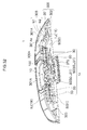
- the dynamic speaker device for example, as shown in Fig. 1 , includes a frame 3J, a cone-shaped diaphragm 21J, an edge 4J through which the diaphragm 21J is supported by the frame 3J, a voice coil bobbin 610J applied to the inner periphery part of the diaphragm 21J, a damper 7J through which the voice coil bobbin 610J is supported by the frame 3J, a voice coil 611J wound around the voice coil bobbin 610J, a yoke 51J, a magnet 52J, a plate 53J, and a magnetic circuit having a magnetic gap in which the voice coil 611J is arranged.
- the voice coil bobbin 610J vibrates by a Lorentz force developed in the voice coil 611J in the magnetic gap and the diaphragm 21J is driven by the vibration.
- the typical dynamic type speaker device as described above is configured such that the voice coil 611J is disposed opposite to the sound emission side of the diaphragm 21J and the vibration directions of the voice coil 611J and the voice coil bobbin 610J are the same as the vibration direction of the diaphragm 21J, for example, as shown in Fig. 1 .
- a region for vibration of the diaphragm 21J, a region for vibration of the voice coil bobbin 610J, and a region for arranging the magnetic circuit, etc. are necessarily formed in the vibration direction (sound emission direction) of the diaphragm 21J. Accordingly, the total height of the speaker device necessarily becomes comparatively large.
- the dimension of the above-mentioned speaker device in the vibration direction of the diaphragm 21J includes (a) the total height of the cone-shaped diaphragm 21J in the vibration direction and the edge 4J through which the diaphragm 21J is supported by the frame 3J, (b) the height of the voice coil bobbin from the joining part of the diaphragm 21J and the voice coil bobbin 610J to the upper end of the voice coil 611J, (c) the total height of the voice coil, (d) the height mainly of the magnet of the magnetic circuit, corresponding to the height from the lower end of the voice coil 611J to the upper end of the yoke 51J, (e) the thickness mainly of the yoke 51J of the magnetic circuit, etc.
- the speaker device as described above requires sufficient heights of the above-mentioned (a), (b), (c), and (d) to ensure a sufficient vibration stroke of the diaphragm 21J. Further, the speaker device requires sufficient heights of the above-mentioned (c), (d), and (e) to secure a sufficient electromagnetic force. Accordingly, particularly in a speaker device adapted to a large sound volume, the total height of the speaker device inevitably becomes large.
- the vibration direction of the voice coil bobbin 610J is the same as that of the diaphragm 21J in the conventional speaker device as described above, the total height of the speaker device inevitably becomes large to secure a vibration stroke of the voice coil bobbin 610J, when seeking a large volume sound with large amplitude of vibration of the diaphragm 21J. Thus, it becomes difficult to make a thin device. In other words, the problem is that making a thin device and securing a loud sound are contradictory to each other.
- the speaker device when a speaker unit is arranged in the cabinet, it is required to provide a large depth of the cabinet on the rear side of the speaker unit corresponding to total height of the speaker unit, when securing a sufficient space volume on the rear side of the speaker unit.
- the speaker device as a whole including the cabinet becomes large, and thereby there is a problem of limiting installation space for the speaker device.
- the installation space for the speaker device is limited specifically in an in-car speaker, etc., and thereby there is a problem that the speaker unit may not be arranged in the cabinet having a sufficient volume.
- an object of the present invention is to provide a thin speaker device capable of emitting a reproduced sound at large volume, a thin speaker device capable of efficiently transmitting the vibration of the voice coil to the diaphragm by converting a direction of a vibration produced by the voice coil, enabling the whole speaker device including the cabinet to be thin, while providing preferable acoustic performance of the speaker unit by securing a sufficient volume in the cabinet, etc.
- a speaker device has at least a configuration according to the following independent claims:
- a speaker device comprising a speaker unit and a cabinet on or in which the speaker unit is mounted, wherein the speaker unit includes a diaphragm, a static part supporting the diaphragm vibratably in a vibration direction and a driving part provided at the static part to vibrate the diaphragm in response to an audio signal, and the driving part includes a magnetic circuit forming a magnetic gap, a voice coil vibrating in a direction different from the vibration direction of the diaphragm upon the inputted audio signal and a rigid vibration direction converter part configured to convert the direction of the vibration of the voice coil and transmit the vibration to the diaphragm, and the vibration direction converter part is arranged such that one end is angle-variably coupled to the voice coil directly or via other member while another end is angle-variably coupled to the diaphragm directly or via other member, the vibration direction converter part being obliquely disposed with respect to the vibration direction of the diaphragm and the vibration direction of the voice coil respectively, and the cabinet is configured to form a prescribed
- a speaker device comprising a speaker unit and a cabinet on or in which the speaker unit is mounted, wherein the speaker unit includes a diaphragm, a static part supporting the diaphragm vibratably in the vibration direction and a driving part provided at the static part to vibrate the diaphragm in response to an audio signal, and the driving part includes a magnetic circuit forming a magnetic gap in a direction different from the vibration direction of the diaphragm, a voice coil vibrating along the magnetic gap and a vibration direction converter part configured to convert the direction of the vibration of the voice coil and transmit the vibration to the diaphragm, and the vibration direction converter part includes a link body configured to angle convert a link part that is formed between the voice coil and the diaphragm, and the cabinet is configured to form a prescribed space between the cabinet and the speaker unit.
- a speaker device includes a speaker unit and a cabinet on or in which the speaker unit is mounted. And, the cabinet has a prescribed space between the cabinet and the speaker unit.
- the speaker unit which is described hereinafter, includes a diaphragm, a static part supporting the diaphragm vibratably in the vibration direction and a driving part provided at the static part to vibrate the diaphragm in response to an audio signal.
- the driving part includes a magnetic circuit forming a magnetic gap, a voice coil vibrating in a direction different from the vibration direction of the diaphragm upon the inputted audio signal and a rigid vibration direction converter part configured to convert the direction of the vibration of the voice coil and transmit the vibration to the diaphragm.
- the vibration direction converter part is arranged such that one end is angle-variably coupled to the voice coil directly or via other member, while another end is angle-variably coupled to the diaphragm directly or via other member, the vibration direction converter part being obliquely disposed with respect to the vibration direction of the diaphragm and the vibration direction of the voice coil respectively.
- the speaker unit includes a diaphragm, a static part supporting the diaphragm vibratably in the vibration direction and a driving part provided on the static part to vibrate the diaphragm in response to an audio signal.
- the driving part includes a magnetic circuit forming a magnetic gap in a direction different from the vibration direction of the diaphragm, a voice coil vibrating along the magnetic gap and a vibration direction converter part configured to convert the direction of the vibration of the voice coil and transmit the vibration to the diaphragm.
- the vibration direction converter part includes a link body configured to angle convert a link part that is formed between the voice coil and the diaphragm.
- the speaker device that includes a configuration described above a large amplitude of vibration of the voice coil in the speaker unit] has little direct effect on the thickness of the speaker unit in sound emission direction, since vibration direction converter part converts the direction of the vibration produced by the voice coil and transmits the vibration to the diaphragm. Therefore, it is possible to make the speaker unit thin while achieving the speaker unit making a louder sound.
- the cabinet at which the speaker unit described above is placed, may be configured to have a large volume in a space between the cabinet and the speaker unit even when the speaker unit is housed in the cabinet having a small depth, since the speaker unit may be made thin. As such, the whole speaker device including the cabinet may be made thin, and thus an improved installation space for the speaker device may be secured.
- the speaker unit may provide a preferable acoustic performance with a space having a sufficient volume, which is made on the rear side of the speaker unit in the cabinet. If a space volume in the cabinet is small, air in the cabinet, which is subject to repeated contraction and expansion, acts as a spring preventing vibration of the diaphragm, thereby degrading acoustic performance. However, in the embodiment according to the present invention, it is possible to restrain such degradation of acoustic performance by securing a sufficient space volume in the cabinet even if the cabinet has a short depth.
- Fig. 2 is a view illustrating a basic configuration of the speaker device according to an embodiment of the present invention
- Fig. 2(a) is a cross-sectional view taken along X-axis direction
- Fig. 2(b) is a view illustrating an operation of the driving part
- the speaker unit 1U includes a diaphragm 10, a static part 100 supporting the diaphragm 10 vibratably in the vibration direction and a driving part 14 arranged at the static part 100 to vibrate the diaphragm 10 in response to an audio signal.
- the driving part 14 includes a magnetic circuit 20 forming a magnetic gap 20G, a voice coil 30 vibrating in a direction different from the vibration direction of the diaphragm 10 upon the inputted audio signal and a vibration direction converter part 50 to convert the direction of the vibration produced by the voice coil 30 and transmit the vibration to the diaphragm 10.
- the voice coil 30 itself may connect with the vibration direction converter part 50, while the voice coil 30 is supported by a voice coil support part 40 as shown in the drawings.
- the vibration direction of the voice coil 30 is X-axis direction and two directions orthogonal to X-axis direction are Y-axis direction and Z-axis direction respectively.
- the diaphragm 10 may be formed substantially in a rectangular shape, a circular shape, an ellipsoidal shape or other shapes in the plan view. Further, the cross-sectional shape of the diaphragm 10 may be formed in a prescribed shape, for example, such as a tabular shape, a dome shape, a cone shape, etc. The cross-sectional shape of the diaphragm 10 is planar as shown in the drawings, however it may be formed in a curved shape. Further, the speaker unit 1U may be made thin by making the total height of the diaphragm 10 comparatively small as necessary.
- the static part 100 is a collective term for those that support vibrations of the diaphragm 10, the driving part 14, etc., which includes the frame 12 and those that have also a function of the frame 12 such as an after-mentioned yoke, a mounting unit, etc.
- the static part 100 is, however, not necessarily completely static.
- the whole static part 100 may vibrate subject to vibration of the driving part 14 or other force.
- the outer periphery part of the diaphragm 10 is supported via an edge 11 by the frame 12 as the static part 100.
- the driving part 14 has the magnetic circuit 20, the voice coil 30 and the vibration direction converter part 50.
- the voice coil 30 vibrates in one axis direction along the magnetic gap 20G of the magnetic circuit 20 and the vibration direction converter part 50 converts the direction of the vibration and transmits the vibration to the diaphragm 10.
- the voice coil 30 vibrates in X-axis direction and the diaphragm 10 is vibratably arranged in Z-axis direction orthogonal to X-axis direction as shown in the drawings.
- the vibration direction converter part 50 converts the vibration of the voice coil 30 in X-axis direction into a vibration at obliquely disposed angle of its own displacement, and thus vibrating the diaphragm 10 in Z-axis direction.
- the magnetic circuit 20 has a magnet 21 (21A, 21B) and a magnetic pole member(yoke)22 (22A, 22B) such that a plurality of the magnetic gaps 20G are arranged in vibration direction of the voice coil 30, for example, in X-axis direction.
- the magnetic pole direction of the magnet 21 (21A, 21B) is set such that magnetic field directions of a pair of the magnetic gaps 20G are opposite to each other ( ⁇ Z-axis direction).
- the voice coil 30 made up of a wound conducting member is arranged such that currents flow in directions opposite to each other ( ⁇ Y-axis direction) in the magnetic gap 20G having magnetic fields in directions opposite to each other.
- a driving force (Lorentz force, electromagnetic force) may be developed in the voice coil 30 in directions ( ⁇ X-axis directions) along the magnetic gap 20G.
- Relationship of arrangement between the magnet 21 and the magnetic pole member (yoke) 22 is not limited to the example shown in the drawings.
- Rigidity bending rigidity, torsional rigidity included
- a tabular insulating member as the voice coil support part 40 has a plurality of conducting layers formed at the outside of a conducting wire.
- the conducting layer 43 is electrically connected to a lead wire 31 (see Fig. 17 ) that is pulled out from the start point and the end point of the conducting wire.
- the lead wire 31 is configured, for example, with a part of an after-mentioned conducting member. Further, the lead wire 31 is electrically connected to outside via an after-mentioned holding part 15, thus functioning as a junction wire for inputting an outside audio signal into the voice coil 30. Further, for example, when a conducting wire free from the voice coil is wound in the speaker unit as the junction wire, an additional space for wiring by winding is required. However, since the conducting layer 43 (see Fig. 17 ) is electrically connected to a lead wire 31 (see Fig. 17 ) that is pulled out from the start point and the end point of the conducting wire.
- the lead wire 31 is configured, for example, with a part of an after-mentioned
- the voice coil 30 and the voice coil support part 40 are formed to be tabular, but they are not limited to this form and may be formed to be tubular. Further if the voice coil 30 or the voice coil support part 40 supporting the voice coil 30 are formed to be tubular, a tabular lid, which enables angle-variable coupling of the vibration direction converter part, may be connected with the end of the vibration direction converter part 50.
- the voice coil 30 is formed by winding the conducting wire (conducting member) to which the audio signal is inputted.
- the voice coil 30 in itself is vibratably arranged at the static part 100 or is vibratably arranged at the static part 100 via the voice coil support part 40.
- the voice coil support part 40 may be formed, for example, with a tabular insulating member, and the voice coil 30 is supported on the surface of or inside the voice coil support part 40.
- the voice coil support part 40 is formed, for example, with the tabular insulating member, rigidity (bending rigidity and torsional rigidity included) may be added to the voice coil 30 as a whole.
- the voice coil 30 is held on the static part 100 with a holding part not shown in the drawings.
- the holding part is configured to vibratably hold the voice coil 30 or the voice coil support part 40 in vibration direction (for example, X-axis direction) with respect to the static part 100 and restrict them not to move in other directions.
- the holding part is deformable in the vibration direction (for example, X-axis direction) of the voice coil 30.
- the holding part may be formed with a curved plate member having rigidity in a direction crossing this vibration direction.
- the length of the voice coil 30 in the direction orthogonal to the vibration direction of the voice coil thereof may be comparatively long with respect to the length of the voice coil 30 in the vibration direction of the voice coil so that a comparatively large driving force may be produced when driving a speaker.
- the vibration direction converter part 50 has one end angle-variably connected to the voice coil 30 directly or via other member, and has another end angle-variably connected to the diaphragm 10 directly or via other member.
- the vibration direction converter part 50 is obliquely disposed with respect to each of vibration directions of the diaphragm 10 and the voice coil 30.
- the vibration direction converter part 50 includes a rigid link part 51 angle-variably and obliquely disposed between the voice coil 30 or the voice coil support part 40 and the diaphragm 10, and a hinge part 52, which is formed at both ends of the link part 51 and functions as a fulcrum for angle change of the vibration direction converter part 50.
- the connecting part 53 of the vibration direction converter part 50 is connected to the diaphragm 10, the voice coil 30, or an attaching counterpart 200 including other member than the diaphragm 10 or the voice coil 30 with a coupling member including a joining member such as an adhesive or a double-faced tape, and a fastener member such as a screw, etc.
- the hinge part 52 is arranged in proximity of the attaching counterpart 200.
- the connecting part 53 (53A) at the end of the vibration direction converter part 50 is coupled to the voice coil 30 or the voice coil support part 40 via a connecting part 60 as shown in the drawings. However, the connecting part 53 (53A) may be directly connected without the connecting part 60.
- the connecting part 60 is formed between the end of the vibration direction converter part 50 on the voice coil side and the end of the voice coil 30 or the voice coil support part 40 on the side of vibration direction converter part, and thereby both ends are coupled spaced apart in the vibration direction. Further, the connecting part 60 absorbs the thickness of the magnetic circuit 20, thus making the speaker unit thin.
- a contact avoiding part 70 avoiding contact with the hinge part 52 is formed on the surface side of the attaching counterpart 200 in proximity of the hinge part 52 of the vibration direction converter part 50.
- the contact avoiding part 70 also functions as a joining member housing part (restraining part), which houses and restrains the joining member joining the vibration direction converter part 50 and the attaching counterpart 200.
- the contact avoiding part 70 is, for example, a concave portion, a notch part, a groove part, etc., which is formed in a concave shape along the hinge part 52.
- a predetermined space is formed between the hinge part 52 and the surface of the attaching counterpart 200 arranged near the hinge part 52 and thus preventing the adhesive material provided between the vibration direction converter part 50 and the attaching counterpart 200 from affecting the hinge part 52.
- the notch part 71 as the contact avoiding part 70 is formed at the connecting part 60, which is the attaching counterpart 200, such that the notch part 71 is located in proximity of the hinge part 52 (52A), while the concave portion 72 as the contact avoiding part 70 is formed at the diaphragm 10, such that the concave portion 72 is located in proximity of the hinge part 52 (52B).
- the connecting part 53 of the vibration direction converter part 50 and the connecting part 60 or the end face of the diaphragm 10 are applied with the joining member such as adhesive, double-faced tape, etc.
- the adhesive and the end of the double-faced tape running off toward the hinge part 52 enter into the notch part 71 or the concave portion 72, and thus preventing them from contacting and adhering to the hinge part 52.
- the voice coil 30 or the voice coil support part 40 vibrates along the magnetic gap 20G of the magnetic circuit 20, for example, in X-axis direction of the drawings as shown in Fig. 2 (b) . Accordingly, the direction of the vibration is converted by the vibration direction converter part 50 and the vibration is transmitted to the diaphragm 10 such that the diaphragm 10 is vibrated, for example, in Z-axis direction of the drawings, thereby a sound in response to the audio signal is emitted in the sound emission direction SD.
- the thickness of the speaker unit 1U on the rear side of the diaphragm 10 may be made smaller than the thickness of the speaker, of which the voice coil 30 is vibrated in the vibration direction of the diaphragm 10. As such, a thin speaker device, which may reproduce a low frequency range with a high sound pressure, may be realized.
- the thickness in sound emission direction of the speaker unit 1U (total height of the speaker unit) is not increased even if the amplitude of vibration of the diaphragm 10 is increased by increasing the amplitude of vibration of the voice coil 30.
- a thin speaker device which may emit a loud reproduced sound, may be realized.
- the hinge part 52 when the connecting part 53 of the direction converter part 50 and the attaching counterpart 200 are connected to each other by using the adhesive as an joining member, if the adhesive spreads out and runs off toward the hinge part 52 due to the join, and adheres to the hinge part 52, the hinge part 52 may be hardened and lose mobility. Also, when the double-faced tape is used as the joining member, if the end of the double-faced tape runs off toward the hinge part 52 and the double-faced tape adheres to the hinge part 52, the hinge part 52 may be hardened and lose mobility. In addition, the hinge part 52, which is adhered to and hardened by the adhesive, the end of the double-faced tape, etc. adhered thereto, may be subject to fracture by the repetition of bending, folding or rotational motion.
- the part to which the adhesive or the end of the double-faced tape adheres may repeatedly contact with and separate from the diaphragm 10, the voice coil 30 or the attaching counterpart 200 as other members, etc., and thus an abnormal noise (contact sound) may be generated each time.
- the applied volume of the adhesive or the joining area by the double-faced tape is limited such that the adhesive or the double-faced tape does not run off and adhere to the hinge part 52, the coupling force between the vibration direction converter part 50 and the attaching counterpart 200 may be reduced, then detachment, etc. may occur at the end face, causing abnormal noise, or if a total detachment occurs, the speaker may eventually be fractured.
- the hinge part 52 since the hinge part 52 is arranged near the attaching counterpart 200, the hinge part 52 may contact the attaching counterpart 200. Therefore, the hinge part 52 damages, or there is a case that the vibration direction converter part 50 cannot bend, fold or rotate with respect to the attaching counterpart 200.
- the contact avoiding part 70 is formed on the surface side of the attaching counterpart 200 in proximity of the hinge part 52, it is possible to prevent the attaching counterpart 200 from contacting the hinge part 52 and restrain the generation of abnormal noise, etc. due to the contact.
- the joining member such as the adhesive, double-faced tape, etc., which is used for coupling the connecting part 53 of the vibration direction converter part 50 and the attaching counterpart 200, runs off, the joining member enters into the contact avoiding part 70 that also functions as a joining member restraining part, and thus it is possible to restrain adherence of the joining member to the hinge part 52 causing hindrance to mobility thereof.
- the function of the hinge part 52 may be maintained while the coupling force between the vibration direction converter part 50 and the attaching counterpart 200 is maintained large. Since the vibration direction converter part 50 securely bends, folds or rotates with respect to the attaching counterpart 200, contact of the hinge part 52 to the attaching counterpart 200, generation of the abnormal noise, etc. due to fracture may be restrained.
- Figs. 3 and 4 are views illustrating a configuration example and an operation of the vibration direction converter part 50.
- the rigid vibration direction converter part 50 direct-converting the vibration of the voice coil 30 and transmitting it to the diaphragm 10, has hinges 52 formed on the sides of the diaphragm 10 and the voice coil 30 respectively, and has the link part 51 obliquely disposed with respect to the vibration direction of the voice coil 30.
- the hinge part 52 is a part that rotatably joins two rigid members or a part that bends or bendably joins integrated two rigid parts, while the link part 51 is a rigid part having the hinge parts 52 formed at the ends.
- the rigidity means that the members and the parts are not so deformable that the vibration of the voice coil 30 can be transmitted to the diaphragm 10. It does not mean that they are totally undeformable.
- the link part 51 can be formed in a plate shape or in a rod shape.
- one link part 51 has the hinge parts 52 (52A, 52B) formed at both ends such that the one hinge part 52A is formed at the end of the voice coil 30 or the voice coil support part 40, while another hinge part 52B is formed on the side of the diaphragm 10.
- Another hinge part 52B may be connected to the diaphragm 10 or connected to the diaphragm 10 via other member.
- a conventional member may be used as other member.
- a metal material, etc. improving join strength between the hinge part 52 and the diaphragm 10, may be selected (diaphragm 10 is not shown in Fig. 3 ).
- Fig. 3(a) shows that the link part 51 is in the middle position of the vibration.
- the link part 51 is obliquely disposed between the voice coil 30 (or voice coil support part 40) and the diaphragm 10 at an angle ⁇ 0 .
- the hinge part 52B on the side of the diaphragm 10 is arranged at the position Z 0 apart from the voice coil 30 by distance Ho in the vibration direction of the diaphragm 10.
- the vibration direction of the voice coil 30 (or voice coil support part 40) is restricted such that it may vibrate in one axis direction (for example, X-axis direction), while the vibration direction of the diaphragm 10 is restricted such that it may vibrate in a direction (for example, Z-axis direction) different from the vibration direction of the voice coil 30.
- the vibration direction converter part 50 including the link part 51 and the hinge part 52 (52A, 52B), converts vibration of the voice coil 30 to the change in the angle of the link part 51 obliquely disposed and transmits it to the diaphragm 10, and thus vibrating the diaphragm 10 in a direction different from the vibration direction of the voice coil 30.
- Fig. 4 is a view illustrating another configuration example and the operation of the vibration direction converter part 50. Specifically, Fig. 4(b) shows a state of the vibration direction converter part 50 when the diaphragm 10 is positioned in a reference position, Fig. 4(a) shows a state of the vibration direction converter part 50 when the diaphragm 10 is displaced to the sound emission side from the reference position and Fig. 4(c) shows a state of the vibration direction converter part 50 when the diaphragm 10 is displaced in the direction opposite to the sound emission side from the reference position (diaphragm 10 is not shown).
- the vibration direction converter part 50 has a function that the link part 51 can angle-convert by receiving reaction force from a static part 100 such as the frame 12 positioned on the opposite side of the diaphragm.
- the vibration direction converter part 50 includes a first link part 51A having one end on the side of the voice coil 30 as a hinge part 52A while another end on the side of the diaphragm 10 as a hinge part 52B and a second link part 51B having one end as a hinge part 52C to the middle part of the first link part 51A while another end as a hinge part 52D to the static part 100, and the first link part 51A and the second link part 51B are obliquely disposed in different directions with respect to the vibration direction of the voice coil 30.
- the vibration direction converter part 50 includes a first link part 51A having one end on the side of the voice coil 30 as a first hinge part 52A while another end on the side of the diaphragm 10 as a second hinge part 52B and a second link part 51B having one end as a third hinge part 52C to the middle part of the first link part 51A while another end as a fourth hinge part 52D to the static part 100, and the first hinge part 52A, the second hinge part 52B and the fourth hinge part 52D are located on the circumference of a circle with a diameter of substantially the same length as the first link part 51A, having the third hinge part 52C as the center.
- the hinge part 52 D supported by the static part 100 (or frame 12), is only the hinge part that does not change position, and thus providing reaction force from the static part 100 for the link part 51. Accordingly, when the voice coil 30 (or the voice coil support part 40) moves from the reference position X 0 by ⁇ X 1 in the X-axis direction, angles of the first link part 51A and the second link part 51B that are obliquely disposed in different directions are increased by substantially the same angle as shown in Fig. 4(a) , and thus the hinge part 52B, receiving reaction force from the static part 100 at the hinge part 52D, securely pushes up the diaphragm 10 from the reference position Zo by ⁇ Z 1 in the Z-axis direction.
- angles of the first link part 51A and the second link part 51B are decreased by substantially the same angle as shown in Fig. 4(c) , and thus the hinge part 52B, receiving reaction force from the static part 100 at the hinge part 52D, securely pushes down the diaphragm 10 from the reference position Z 0 by ⁇ Z 2 in the direction opposite to the Z-axis direction.
- a length a of a link part from the hinge part 52A to the hinge part 52C, a length b of a link part from the hinge part 52C to the hinge part 52B and a length c of a link part from the hinge part 52C to the hinge part 52D are configured to be substantially the same as each other, and thereby the hinge part 52A and the hinge part 52D are preferably arranged substantially in parallel with the moving direction of the voice coil 30.
- the angle defined by the line passing through the hinge part 52A and the hinge part 52D and the line passing through the hinge part 52B and the hinge part 52D becomes a right angle.
- the hinge part 52B between the first link part 51A and the diaphragm 10 moves in the Z-axis direction that is perpendicular to the X-axis, and thus it is possible to convert the vibration direction of the voice coil 30 to its orthogonal direction and transmit the vibration to the diaphragm 10.
- Figs. 5 and 6 are views illustrating a formation example of the vibration direction converter part ( Fig. 5(a) is a side view, Fig. 5(b) is a perspective view and Fig. 5(c) is an enlarged view of part A).
- the vibration direction converter part 50 includes the link part 51 and the hinge parts (52A, 52B) formed at both ends of the link part 51 as described above.
- connecting parts 53 first connecting part 53A and second connecting part 53B
- hinge parts 52 first connecting part 53A and second connecting part 53B
- the first connecting part 53A connected to the voice coil 30 or the voice coil support part 40 directly or via other member, integrally vibrates with the voice coil 30, while the second connecting part 53B, connected to the diaphragm 10 directly or via other member, integrally vibrates with the diaphragm 10.
- the link part 51, the hinge parts 52A and 52B, the first and second connecting parts 53A and 53B are integrally formed, and the hinge parts 52A and 52B are formed with a bendable continuous member continuing between the parts of both sides over the hinge parts 52A and 52B.
- This continuous member may be a member configuring the link part 51 and the first and the second connecting part 53A and 53B as a whole, or may be a member configuring the link part 51 and a part of the first and second connecting parts 53A and 53B.
- the link part 51 may support the diaphragm 10 over a wide range, and thereby it is possible to vibrate the diaphragm 10 in the same phase.
- the term "fold” includes "bend" in its conceptual scope.
- the vibration direction converter part 50 is formed with a plate shape member
- the hinge part 52 is linearly formed extended in a width direction as shown in Fig. 5 (b) .
- the link part 51 is required to be rigid and not to be deformable. Since the hinge part 52 is required to be bendable, the integral member is configured to have a different property by forming the thickness t2 of the hinge part 52 smaller than the thickness t1 of the link part 51 or the connecting part 53.
- the change in thickness of the hinge part 52 and the link part 51 is formed on a slant face, and the slant faces 51t and 53t, facing the ends of the parts of both sides over the hinge part 52, are formed. As such, when the link part 51 is angle-varied, interference to the angle variation by thickness of the link part 51 may be restrained.
- a concave portion or notch part 71 which acts as a contact avoiding part 70, is formed at the end of the connecting part 60 that is an attaching counterpart 200 arranged near the hinge part 52A, such that a space is formed between the hinge part 52A and the connecting part 60 as shown in Fig. 5(a) .
- the notch part is formed in a slantwise cross-sectional shape.
- a concave portion or notch part 72 which acts as a contact avoiding part 70, is formed at the diaphragm 10 that is an attaching counterpart 200 arranged near the hinge part 52B, such that a space is formed between the hinge part 52B and the diaphragm 10.
- the concave portion is formed in a curved cross-sectional shape.
- contact between the hinge parts 52A, 52B and the attaching counterpart 200 may be restrained.
- the adhesive since the adhesive only adheres to a non-hinge part (unbendable or unfoldable rigid part) even if the adhesive adheres, interference to bending or folding of the hinge parts 52A, 52B may be restrained.
- a link part or a connecting part is configured by integrating a bendable continuous member and a rigid member, and a hinge part is a part that is configured by the continuous member.
- the link part 51 or the connecting part 53 is configured by joining a rigid member 50Q to the surface of a continuous member 50P that is a bendable sheet-shaped member.
- the continuous member 50P continuously extends between the parts of both sides over the hinge part 52, and the hinge part 52 is bendably formed substantially only by the continuous member 50P.
- the link part 51 or the connecting part 53 which is formed by joining the rigid member 50Q to the continuous member 50P, may be formed as a rigid part.
- the rigid members 50Q are applied to sandwich the continuous member 50P to form the link part 51 or the connecting part 53. Also, the part, not applied with the rigid member 50Q, becomes the hinge part 52.
- the rigid member forming the link part 51 is formed in multiple layers laminated by the rigid members 50Q1 and 50Q2. Further, in Fig. 6(c) , the rigid member 50Q1 and the rigid member 50Q2 may be formed in a multiple-layer structure. As such, the bendable hinge part 52 and the rigid link part 51 and connecting part 53 may be integrally formed by partially joining the rigid member 50Q to the bendable continuous member 50P.
- the continuous member 50P is preferably configured to have strength and durability durable against repeated bending of the hinge part 52 when the speaker unit is driven, and have flexibility making little noise when bending is repeated.
- the continuous member 50P may be formed with a woven or an unwoven material made of high-strength fiber.
- the woven material plain weave with uniform material, plain weave having different warp and weft material threads, plain weave with alternately changed thread material, plain weave with twisted union yarn and plain weave with paralleled yarn.
- plain weaves there may be applied triaxial and quadraxial woven fabrics, triaxial and quadraxial continuous non-woven fabric of glued layer , knitting, fabric with paralleled yarn in one direction, etc.
- the high-strength fiber When the high-strength fiber is applied partially or as a whole, sufficient strength against vibration of the voice coil 30 or the voice coil support part 40 may be achieved by arranging the high-strength fiber in the vibration direction of the voice coil support part 40.
- durability When applying both the warp and the weft thread as the high-strength fiber, durability may be improved with a uniform tensile force given to the warp and the weft thread by inclining both fiber directions by 45° with respect to the vibration direction of the voice coil support part 40.
- the high-strength fiber aramid fiber, carbon fiber, glass fiber, etc. may be used. Further, a damping material may be applied to adjust characteristic such as bending stress and rigidity of the continuous member.
- the vibration direction converter part 50 may be configured by joining the rigid member 50Q, which is molded in a plate shape, to the surface of the continuous member 50P other than the part of the hinge part 52 by using adhesive as a joining material. Further, if thermosetting resin is used as the rigid member 50Q, the vibration direction converter part 50 may be configured by impregnating partially the link part 51 or the connecting part 53 of the fibrous continuous member 50P with resin and then hardening it.
- the continuous member 50P and the rigid member 50Q may be integrated at the link part 51 and the connecting part 53 by using insert molding.
- US20050127233 Publication No. US2005/253298
- US20050128232 Publication No. US2005/253299
- Figs. 7 and 8 are views illustrating a speaker device adopting the above-mentioned vibration direction converter part
- Figs. 7(a) and 8(a) are cross-sectional views taken in X-axis direction
- Figs. 7(b) and 8(b) are views illustrating an operation of the driving part.
- the same symbols are applied to the same parts and a part of duplicate descriptions is eliminated.
- a link body 50L is configured to include the first connecting part 53A that is connected to the voice coil support part 40 and vibrates integrally with the voice coil support part 40 and the second connecting part 53B that is connected to the diaphragm 10 and vibrates integrally with the diaphragm 10 as well as a plurality of link parts.
- the vibration direction converter part 50 is formed with the link body 50L including the rigid first link part 51A and second link part 51B.
- the first connecting part 53A is located at one end of the first link part 51A via the hinge part 52A while the second connecting part 53B is located at another end of the first link part 51A via the hinge part 52B.
- the middle part of the first link part 51A is located at one end of the second link part 51B via the hinge part 52C while the connecting part 53C, which is static with respect to vibration of the voice coil support part 40, is located at another end of the second link part 51B via the hinge part 52D.
- the first connecting part 53A is connected to the end of the voice coil support part 40 directly or via the connecting part 60
- the second coupling part 53B is directly connected to the diaphragm 10
- the static connecting part 3C is coupled to the bottom portion 12A of the frame 12 that is the static part 100.
- a concave portion or a notch part 73 which acts as a contact avoiding part 70, is formed at the bottom portion 12A of the frame 12 that is an attaching counterpart 200 arranged near the hinge part 52D, such that a space is formed between the hinge part 52D and the bottom portion 12A of the frame 12.
- the notch part is formed.
- the first link part 51A and the second link part 51B are obliquely disposed in different directions with respect to the vibration direction (X-axis direction) of the voice coil support part 40 and the static part 100 is provided on the opposite side of the diaphragm 10 with respect to the vibration direction converter part 50.
- the static part 100 is formed with the bottom portion 12A of the frame 12
- a yoke 22A of a magnetic circuit 20 may be the static part 100 instead of the bottom portion 12A of the frame 12 by extending the yoke 22A of the magnetic circuit 20 to the position under the vibration direction converter part 50.
- the hinge part 52A on the side of the voice coil support part 40 moves in the X-axis direction in accordance with the movement of the voice coil support part 40 while the hinge part 52D connected to the static part 100 is fixed.
- the movement of the hinge part 52A is converted to changing angles of the first link part 51A and the second link part 51B, and thus the hinge part 52B on the side of the diaphragm 10 is moved in the vibration direction of the diaphragm 10 (for example, Z-axis direction).
- the speaker unit 1 U (1B) shown in Fig. 8 is configured with the driving parts 14 shown in Fig. 7 symmetrically disposed opposite to each other, which includes the driving parts 14(R) and 14(L), respectively.
- Each of the driving parts 14(R) and 14(L) includes a link body 50L(R) or 50L(L), a voice coil support part 40(R) or 40(L), a magnetic circuit 20(R) or 20(L) and a connecting part 60(R) or 60(L).
- the link bodies 50L(R) and 50L(L) configure the vibration direction converter part 50 such that a pair of the first link parts 51A, a pair of the second link parts 51B, a pair of the first connecting parts 53A, the second connecting part 53B and the static connecting part 53C, which are disposed opposite to each other, are integrally formed.
- a pair of the first connecting parts 53A are connected to the voice coil support part 40 respectively
- the second connecting part 53B is connected to the diaphragm 10
- the static connecting part 53C is connected to the bottom portion 12A of the frame 12.
- the diaphragm 10 may be driven by two combined driving forces of the driving parts 14(R) and 14(L) by setting the vibration directions of the voice coil support part 40(R) and 40(L) synchronously opposite to each other. Further, since a plurality of hinge parts 52B are provided on the side of the diaphragm 10, the number of support points on the diaphragm 10 is increased, thereby the phase of vibration of the diaphragm 10 may become uniform.
- Figs. 9 and 10 are views illustrating more specific vibration direction converter part ( Fig. 9(a) is a perspective view, Fig. 9(b) is an enlarged view of part A in Fig. 9(a) , Fig. 10(a) is a plan view illustrating a flattened whole part by unfolding the vibration direction converter part and Fig. 10(b) is a side view illustrating a flattened whole part by unfolding the vibration direction converter part.
- the vibration direction converter part 50 is formed with a single integrated component.
- the vibration direction converter part 50 is formed with a pair of the first link parts 51A, hinge parts 52A and 52B formed at both ends of the first link parts 51A, a pair of the second link parts 51B and hinge parts 52C and 52D formed at both ends of the second link parts 51B.
- the first connecting parts 53A are formed at one ends of a pair of the first link parts 51A via the hinge parts 52A
- the second connecting part 53B is formed between hinge parts 52B formed at other ends of a pair of the first link parts 51A
- the static connecting part 53C is formed between the hinge parts 52D formed at other ends of the second link parts 51B.
- the first link parts 51A, 51A and the second connecting part 53B are bent in a convex shape and the second link parts 51B, 51B and the static connecting part 53C are bent in a concave shape.
- the hinge part 52A is bendably formed with the above continuous member 50P.
- the above rigid member 50Q is attached to the first link part 51A and also to the first connecting part 53A.
- the first connecting part 53A is joined by the above rigid member 50Q.
- all of the above-mentioned hinge parts are formed in the similar configuration.
- slant faces 51t and 53t are formed opposite to each other in each hinge part.
- the vibration direction converter part 50 including the link parts 51A, 51B, each hinge part and the connecting part 53A, 53B, 53C, is formed with an integral sheet-shaped member.
- the hinge parts 52A are formed linearly crossing the integral sheet-shaped member, while the hinge parts 52B, 52C, 52D are formed partially crossing the integral sheet-shaped member.
- a pair of notch parts 50S are formed in a longitudinal direction of the integral sheet-shaped member such that the second link parts 51B, 51B and the static coupling part 53C are cut out and formed.
- the vibration direction converter part 50 is formed, for example, by applying resin material forming the rigid member 50Q to the whole surface of the continuous member 50P that is a sheet-shaped member, such that the resin material is laminated on the continuous member 50P, and cutting in a V-shape to form each hinge part and the slant faces 51t and 53t at both sides thereof. After that, the above-mentioned notch part 50S is formed and the resin material is hardened. A liquid unhardened resin material or resin film may be used as the resin material used in this embodiment.
- each hinge part and the slant faces 51t and 53t at both sides thereof may be formed at the same time as forming the rigid member 50Q with the resin material. It is preferable that a cross-sectional V-shape groove or a concave portion is formed preliminarily in a die, which is used to mold the rigid member 50Q.
- Figs. 11 , 12 and 13 are views illustrating other examples of the vibration direction converter part 50 ( FIG. 11(a) is a side view, Fig. 11(b) is a perspective view, Fig. 12 is a view illustrating an operation and Figs. 13(a) and 13(b) are views illustrating formation examples).
- the vibration direction converter part 50 (link body 50L) includes a pair of driving parts.
- the vibration direction converter parts 50 are substantially symmetrically disposed opposite to each other and a parallel link is formed with a plurality of link parts.
- the vibration direction converter part 50 includes a pair of first link parts 51A(R) and 51A(L) having a hinge part 52A(R) and 52A(L) to a first connecting part 53A (R) and 53A (L) at one end, and having a hinge part 52B(R) and 52B(L) to a second connecting part 53B at another end. Also, the vibration direction converter part 50 includes a pair of second link parts 51B(R) and 51B(L) having hinge parts 52C(R) and 52C(L) to the middle parts of the first link parts 51A(R) and 51A(L) at one end, and having hinge parts 52D(R) and 52D(L) to the static connecting part 53C at another end.
- the first connecting part 53A is connected to the voice coil 30 or the voice coil support part 40 directly or via the connecting part 60 as other member, while the second connecting part 53B is connected to the diaphragm 10 and the static connecting part 53C is connected to the bottom portion 12A of the frame 12 that is the static part 100, the yoke 22, etc. forming the magnetic circuit 20.
- vibration direction converter part 50 includes a pair of third link parts 51C(R) and 51C(L) having hinge parts 52E(R) and 52E(L) at one end to a pair of the connecting parts 53D(R) and 53D(L) integrally extending from the first connecting part 53A (R) and 53A (L), and having hinge parts 52F (R) and 52F (L) at another end to a connecting part 53E that is integral with the second connecting part 53B.
- first link part 51A(R) and the third link part 51C(R), the first link part 51A(L) and the third link part 51C(L), the second link part 51B(R) and the third link part 51C(L), and the second link part 51B(L) and the third link part 51C(R) form parallel links respectively.
- This link body 50L of the vibration direction convertor part 50 substantially includes a function combining the link body of the embodiment shown in Fig. 7 and the parallel link body.
- Each link part and connecting part are formed by integrating the continuous member 50P with the rigid member 50Q, while each hinge part between link parts is linearly formed with the bendable continuous member 50P, and thus link parts are mutually integrally formed via hinge parts.
- the second connecting part 53B arranged near the hinge parts 52F (R) and 52F (L) and a pair of the connecting part 53D(R) and 53D(L) arranged near the hinge parts 52A(R) and 52A(L) form concave portions 76 as the contact avoiding part 70, such that a space is formed between each hinge part and connecting part.
- the static connecting part 53C functions as the static part 100.
- the vibration direction converter part 50 when the hinge parts 52A(R) and 52A(L) is moved from the reference position X0 to X1 in the X-axis direction in accordance with vibration of the voice coil support part 40, the second connecting part 53B and the connecting part 53E integrally with the second connecting part 53B moving up keeping a parallel state by the parallel link body, while the first link parts 51A(R) and 51A(L) and the third link parts 51C(R) and 51C(L), which configure a parallel link, are angle-varied as they are erected.
- hinge parts 52D(R) and 52D(L) are supported at both ends of the static connecting part 53C as the static part, they receive a reaction force from the static part and angle of the first link parts 51A(R) and 51A(L) and the third link parts 51C(R) and 51C(L) is securely varied and the displacement of the hinge parts 52A(R) and 52A(L) from the position X0 to X1 is securely converted to the displacement of the diaphragm 10 from the position Z0 to Z1.
- hinge parts 52D(R) and 52D(L) are supported by the static part, they receives a reaction force from the static part and angle variation of the first link parts 51A(R) and 51A(L) and the third link parts 51C(R) and 51C(L) is securely produced and the displacement of the hinge parts 52A(R) and 52A(L) from the position X0 to X2 is securely converted to the displacement of the diaphragm 10 from the position Z0 to Z2.
- the vibration in the X-axis direction of one voice coil support part 40 is converted to the vibrations in the Z-axis direction of the hinge parts 52B(R) and 52B(L), 52F (R) and 52F (L), and the second connecting part 53B, which vibrate substantially in the same phase and the same amplitude.
- the vibration of the voice coil support part 40 may be transmitted substantially in the same phase to the planar diaphragm 10 with large area.
- a pair of the connecting parts 53B, 53D(R) and 53D(L) and the third link parts 51C(R) and 51C(L) are disposed in a width direction and parallel respectively.
- the first link parts 51A(R) and 51A(L) are formed in a biforked shape, and the hinge parts 52C(R) and 52C(L) to the second link parts 51B(R) and 51B(L) are formed at the middle parts of the first link parts 51A(R) and 51A(L) .
- the second link parts 51B(R) and 51B(L) and the connecting part 53C are placed between a pair of the connecting parts 53B, 53D(R) and 53D(L) and the third link parts 51C(R) and 51C(L), which are disposed in a width direction and parallel.
- the diaphragm 10 can be vibrated and supported by aface, and thereby the whole diaphragm 10 can be vibrated substantially in the same phase and divided vibration may be restrained.
- the first link parts 51A(R) and 51A(L), and the second connecting parts 53B are configured by folding the whole single sheet-shape component forming the link parts in a convex-trapezoid shape, while the second link parts 51B(R) and 51B(L), and the static connecting part 53C are configured by folding a partially taken-out portion of this plate component.
- this vibration direction convertor part 50 is formed by joining a plurality of sheet-shape components 501, 502 (for example, two components) as shown in Fig. 13(a) .
- the first connecting parts 53A(R) and 53A(L), the first link parts 51A(R) and 51A(L), the second link parts 51B(R) and 51B(L), the second connecting parts 53B and the static connecting part 53C are formed in one sheet-shape component 501, while the connecting parts 53D, the third link parts 51C(R) and 51C(L) and the connecting parts 53E are formed in another sheet-shape component 502.
- the third link parts 51C(R) and 51C(L) and the connecting parts 53D(R) and 53D(L) are formed along the first link parts 51A(R) and 51A(L) and the second connecting parts 53B, and an opening 502A is formed in the sheet-shape component 502 corresponding to the second link parts 51B(R) and 51B(L) and the static connecting part 53C.
- the opening 502A formed in another sheet-shape component 502 corresponding to the second link parts 51B(R) and 51B(L) and the static connecting part 53C of one sheet-shape component 501, is formed so as to expand inward from ends of another sheet-shape component 502.
- This configuration may prevent the second link parts 51B(R) and 51B(L), and the static connecting part 53C from contacting another sheet-shape component 502, and thus a smooth movement of the link body may be performed.
- the continuous members 50P, 50P are integrated, and thereby hinge parts 52 may smoothly bend.
- the concave portion or the notch part 76 is formed as the contact avoiding part 70 near the hinge part 52.
- the slant face as shown in Fig. 5(c) is formed at the end of each link part near each hinge part.
- the slant face is formed such that the link parts do not interfere with each other when they bend at the hinge parts.
- the link parts can efficiently bend at the hinge parts.
- the above-mentioned sheet-shape component 501 and the sheet-shape component 502 are integrally formed with the sheet-shape component 502 connected to the end of the sheet-shape component 501 as shown in Fig. 13(c) .
- the vibration direction converter parts 50 shown in Figs. 11 and 12 may be obtained by folding the integrated components along a folding line f in the direction of an arrow.
- the vibration direction converter part 50 may be simply configured by applying resin material forming the rigid member 50Q to the whole surface of the continuous member 50P that is a sheet-shaped member, , cutting in a V-shape to form each hinge part and the slant faces at both sides thereof, and then forming the above-mentioned notch part 50S and opening 502A and hardening the resin material in the same way as shown in Fig. 10 ..
- the rigid member 50Q may be formed with the resin material and molded at the same time. It is preferable that a cross-sectional V-shape groove or a concave portion is preliminarily formed in a die, which is used to mold the rigid member 50Q.
- the link body of the vibration direction converter part 50 may be configured with a single integral component with respect to two opposing voice coil support parts 40, the assembly operation may be simplified as well when configuring a speaker unit provided with a pair of driving parts.
- the hinge parts 52D(R) and 52D(L) may be held at fixed positions even if they are not particularly supported by the frame 12 corresponding to opposing vibrations of the voice coil support parts 40 (a plurality of the voice coil support parts 40 vibrate in directions opposite to each other), and thus the vibration direction converter part may be simply built into a speaker unit.
- the second connecting parts 53B fixed to the diaphragm 10 may be stably moved in parallel in the Z-axis direction corresponding to the opposing vibrations of the voice coil supporting parts 40. Accordingly, it is possible to apply stable vibrations to the planar diaphragm 10.
- the voice coil support part 40 vibrates along the magnetic gap 20G formed in a direction different from the vibration direction admissible for the diaphragm 10, and this vibration is direction-converted by the vibration direction converter part 50 and transmitted to the diaphragm 10, and thereby vibrating the diaphragm 10 to emit a sound in the sound emission direction SD corresponding to the audio signal SS.
- the direction of the magnetic gap 20G is configured to cross the vibration direction of the diaphragm 10 and the thickness direction of the speaker unit 1U (1A, 1B), increasing the driving force of the magnetic circuit 20 or the vibration of the voice coil 30 does not directly affect the size of the speaker unit 1U (1A, 1B) in the thickness direction (Z-axis direction). Accordingly, it is possible to make the speaker unit 1U (1A, 1B) thin while pursuing making a louder sound.
- the vibration direction converter part 50 converts the vibration direction of the voice coil support part 40 and transmits the vibration to the diaphragm 10 through the mechanical link body, transmission efficiency of vibration is high.
- the speaker unit 1U (1A, 1B) shown in Figs. 7 to 8 since angle variation of the first link parts 51A and the second link parts 51B is produced by the vibration of the voice coil support part 40 and reaction force of the static part 100, vibration of the voice coil support part 40 may be more securely transmitted to the diaphragm 100. Accordingly, the speaker unit 1U (1A, 1B) may produce preferable reproducing efficiency.
- interval in the Z-axis direction may be provided between the position of the end 40A of the voice coil support part 40 and the position of the end 50A of the vibration direction converter part 50.
- the length(height) in the Z-axis direction (thickness) of the magnetic circuit 20 can be included in the length in the Z-axis direction of the vibration direction converter part 50, and thus the speaker unit 1U (1A, 1B) may be made thin while securing a sufficient length in the Z-axis direction for the magnetic circuit 20, which is required to secure a driving force.
- a necessary length of the direction converter part 50 (length of link parts 51) may be sufficiently secured even if the speaker unit 1U (1A, 1B) is made thin, and thus the amplitude of vibration of the diaphragm 10 may be comparatively large.
- a bottom portion 61 of the connecting part 60 is configured to slide over the bottom portion 12A of the frame 12 or the static part 100 with a predetermined distance therefrom, and thereby vibration of the voice coil support part 40 may be stabilized. Further, the end of the vibration direction converter part 50 can be linearly moved, and thus the end of the vibration direction converter part 50 connected to the diaphragm 10 can be securely and stably moved.
- the vibration direction converter part 50 shown in Fig. 14 is a modified example of the embodiment shown in Fig. 11 .
- a convex portion 510 is provided on the link part that are subject to bend by opposing vibrations of the voice coil supporting parts 40, thereby rigidity of the link part can be increased.
- the first link part 51A(R) and 51A(L), the second link parts 51B(R) and 51B(L), the connecting parts 53D(R) and 53D(L) and the connecting part 53C are provided with the convex portion 510 respectively. Further, in one example shown in Fig.
- openings 520 are provided in the link part that need no particular strength, weight of the vibration direction converter part can be decreased.
- the connecting part 53B includes the openings 520.
- the weight reduction of the vibration direction converter part is effective to broaden a reproduction characteristic or increase amplitude and a sound pressure level of a sound wave corresponding to predetermined voice currents.
- Figs. 15 to 24 are views illustrating a power feed structure of the speaker unit according to one embodiment of the present invention.
- the speaker unit according to the embodiment of the present invention includes the diaphragm 10, the static part 100 vibratably supporting the vibrating body 10 and the driving part 14, provided in proximity of the static part 100, vibrating the diaphragm 10 in response to an audio signal, while the driving part 14 includes a plurality of the voice coils 30, 30 vibrating in a direction different from the diaphragm 10 upon the inputted audio signal, a plurality of the magnetic circuits 20, 20 having the magnetic gaps 20G, 20G in which the voice coils 30, 30 are arranged respectively and the rigid vibration direction converter part 50, which is obliquely disposed with respect to the vibration directions of the voice coils 30, 30 and the diaphragm 10, transmits the vibrations of the voice coils 30, 30 to the diaphragm 10.
- terminal parts 81, 81 common to a plurality of the voice coils 30, 30, which extend from one voice coil 30 to another voice coil 30 of the plurality of the voice coils 30, 30 in order to input the audio signal to the plurality of the voice coils 30, 30, are provided on the static part 100.
- a pair of the voice coils 30, 30 are provided, a pair of these terminal parts 81, 81 are provided and each one end of the pair of the voice coils 30, 30 is connected to one terminal part 81, while each another end of the pair of the voice coils 30, 30 is connected to another terminal part 81.
- a space for arranging the terminal parts may be reduced to be less than when the terminal parts are provided on one and another end of each voice coil 30.
- the space required for the terminal parts is reduced, and thereby a small sized or thin speaker unit may be produced.
- Wirings are formed at the terminal parts 81, 81 to electrically connect a plurality of the voice coils 30, 30.
- the audio signal may be supplied to each of the plurality of the voice coils 30, 30 via the wirings when the audio signal is inputted to the terminal parts 81, 81.
- Figs. 15(a) and 15(b) are external perspective views of the speaker unit according to the embodiment of the present invention.
- the static part 100 of the speaker unit 1U is configured with a first configuring member 100A and a second configuring member 100B.
- the second configuring member 100B is a frame arranged on the side of the vibration direction converter part 50, and supports a part of the vibration direction converter part 50.
- the terminal parts 81, 81 are arranged between the first configuring member 10A and the second configuring member 100B.
- the first configuring member 100A is a frame arranged on the side of the diaphragm 10, and supports the diaphragm 10 via the edge 11. Further, the first configuring member 100A and the second configuring member 100B support the magnetic circuit 20.
- the first configuring member 100A supports one magnetic pole member (yoke 22) that is one side of the magnetic circuit 20.
- the second configuring member 100B supports another magnetic pole member (yoke 22) that is another side of the magnetic circuit 20. Thereby, a magnetic gap with a prescribed interval is formed between both magnetic pole members while the first configuring member 100A and the second configuring member 100B are coupled.
- An opening 100F is configured with a concave portion formed between the opposing faces of the first configuring member 100A and the second configuring member 100B.
- Projection parts 109 (109A, 109B), supporting the terminal parts 81, 81, are formed at the first configuring member 100A and the second configuring member 100B, and the terminal parts 81, 81 are sandwiched between the projection part 109A and the projection part 109.
- the terminal parts 81, 81 may be concurrently stably fixed.
- the static part 100 includes an outer-periphery frame 101 surrounding the magnetic circuit 20 and a bottom face part 107, and the terminal parts 81, 81 are formed in a shape along the outer-periphery frame 101 and are mounted on the outer- periphery frame 101.
- the terminal parts 81, 81 are not projected out of the outer- periphery frame 101 of the static part 100, the device can be made compact. Further, with the terminal parts 81, 81 mounted on the outer-periphery frame 101, the terminal parts 81, 81 may be stably fixed, and thereby bad connection with the voice coils 30, 30 may be avoided.
- the terminal parts 81, 81 are formed in a shape having a long axis extending along one voice coil 30 to another voice coil 30 and a short axis crossing the long axis. With this longitudinal shape, efficiency of installation space may be improved.
- the terminal parts 81, 81 may be arranged inside the outer- periphery frame 101. Therefore the terminal parts 81, 81 may be arranged without affecting shape or size of the outer circumference of the speaker unit. Further, the terminal parts 81, 81 may be arranged inside the outer-periphery frame 101 by using a technique of insert molding as necessary.
- the respective outer- periphery frames 101, 101 of the first configuring member 100A and the second configuring member 100B include the above-mentioned openings 100F between faces opposing the voice coil 30, and the terminal parts 81, 81 are arranged in the opening 100F.
- the terminal parts 81, 81 act as reinforcing parts reinforcing the opening 100F of the static part 100.
- the terminal parts 81, 81 are provided with a connecting part 81a to wirings 82, 82 (second wiring 80A) that are electrically connected to outside (see Fig. 19 ), and a wiring (first wiring 80A) of the terminal parts 81, 81 and a wiring 82 (second wiring 80B) are electrically connected at the connecting part 81a.
- the wiring 82 (second wiring 80A) is fixed on the side face of the static part 100 and connected to the terminal parts 81, 81.
- the outer-periphery frame 101 of the static part 100 includes a side face on which the wiring 82 (second wiring 80B) is mounted, and guiding parts 106, 106 guiding the wirings 82, 82 are formed on the side face of the static part 100.
- Fig. 16 is a perspective view illustrating an inner structure of the speaker unit (excluding the first configuring member 100A);
- Fig. 17 is a plan view illustrating an inner structure of the speaker unit (excluding the second configuring member 100B);
- Fig. 18 is a perspective view illustrating an inner structure of the speaker unit (excluding the second configuring member 100B);
- Fig. 19 is a perspective view illustrating an inner structure of the speaker unit (illustration of connected state of wiring);
- Fig. 20 is a partial enlarged view illustrating an inner structure of the speaker unit;
- Fig. 21 is a view illustrating installation structure of the voice coil; and
- Fig. 22 is a view illustrating components of the holding part.
- the yoke 22 of the magnetic circuit 20 is provided with a projection part 22p to support the yoke 22 at the first configuring member 100A and the second configuring member 100B.
- the projection part 22p is engaged with a receiving part 105 provided at the first configuring member 100A and the second configuring member 100B.
- Either one of the first configuring member 100A and the second configuring member 100B is provided with a positioning pin 100P positioning the terminal parts 81, 81 (see Figs. 17 and 18 ) and the terminal part 81 may be arranged at a prescribed position with respect to the static part 100 with the positioning pin 100P inserted into a hole 81h (see Fig. 16 ) of the terminal parts 81, 81.
- a concave portion 81b is formed at the side portion of the terminal part 81, 81, and the terminal parts 81, 81 are positioned at the second configuring member 100B with this concave portion 81b engaged with a convex portion 100B1 formed at the second configuring member 100B.
- the voice coil 30 is an annular conducting member formed in a tabular shape, and this conducting member is supported by a rigid base (voice coil support part 40).
- the voice coil 30 or the voice coil support part 40 is unitized by a mounting unit 16 and mounted between the first configuring member 100A and the second configuring member 100B. Further, the voice coil 30 or the voice coil support part 40 is mounted at the mounting unit 16 via the holding part 15, and the voice coil 30 or the voice coil support part 40 is supported by the static part 100 via the holding part 15 with the mounting unit 16 mounted between the first configuring member 100A and the second configuring member 100B. Further, the mounting unit 16 is integrated with the connecting part 60, and the voice coil 30 or the voice coil support part 40 are connected to the vibration direction converter part 50 via the connecting part 60.
- a voice coil lead wire 32 (see Fig. 19 ) connected to a lead wire 31 is formed on the surface of the voice coil support part 40 (base) supporting the voice coil 30.
- the voice coil lead wire 32 is a conducting layer 43, which is pattern-formed outside of the conducting member of the voice coil 30 so as to surround the conducting member.
- a pair of the conducting layers 43 are placed such that the voice coil lead wire 32 electrically connects the conducting member of the voice coil 30 and the holding part 15 and functions as a junction wire for inputting the audio signal to the conducting member of the voice coil 30.
- the end of the terminal parts 81, 81 and the wiring (third wiring 80C) are electrically connected, the wiring (third wiring 80C) of the holding part 15 and the voice coil lead wire 32 are connected, and the wiring 82 (second wiring 80B) is connected to the terminal part 81, 81.
- the wiring (third wiring 80C) may be formed with the holding part 15 as the conducting member. Further, wiring may be separately formed on the holding part 15. Also, the holding part 15 in itself may be formed by using a wiring substrate. Connection between the wiring 82 (second wiring 80B) and the terminal part 81, 81 is made by electrical connection between an end 82a of the wiring 82 and a connecting part 81a of the terminal parts 81, 81.
- the holding part 15 has rigidity in a vibration direction of the diaphragm 10 and has a deformable shape in a vibration direction of the voice coil 30.
- the holding part 15 has a side face linearly extending in the vibration direction (X-axis direction) of the diaphragm 10 and has a curved cross-sectional shape in the vibration direction of the voice coil 30.
- the holding part 15 may restrict the vibration of the voice coil 30 in one axis direction (X-axis direction) and the vibration of the voice coil 30 in other directions is restrained.
- the holding part 15, which supports the voice coil 30 at the static part 100 directly or via other member vibratably in the vibration direction of the voice coil 30, has the first holding part 15 (15A) and the second holding part 15 (15B).
- the first holding part 15 (15A) is arranged on the side of the vibration direction converter part 50 of the voice coil 30, and the second holding part 15 (15B) is arranged on the side opposite to the vibration direction converter part 50 of the voice coil 30.
- the first holding part 15 (15A) is arranged on the right and left sides of the connecting part 60 between the connecting part 60 and the static part 100
- the second holding part 15 (15B) is arranged on the right and left sides of the voice coil 30 on the opposite side of coupling to the connecting part 60
- the first holding part 15 (15A) and the second holding part (15B) substantially symmetrically support the voice coil 30 at the static part directly or via other member. More particularly, in the second holding part 15 (15B), the central part thereof is supported by the static part directly or via other member, and both ends thereof are connected to the right and left ends of the voice coil.
- Fig. 21 is a view illustrating an attachment structure of the voice coil.
- the voice coil 30, winding a conducting member, is supported by the voice coil support part 40, and the voice coil support part 40 is supported by the mounting unit 16 via the holding part 15.
- the voice coil support part 40 includes a voice coil attaching point 41a having an opening in the base 41 made of a tabular insulating material, and one side of the opening is covered with a protection film 44.
- the voice coil 30 is attached in this voice coil attaching point 41a.
- Each of outer ends of a pair of the first holding part 15 (15A) is coupled to the mounting unit 16 on one side of the mounting unit 16, while inner end parts of a pair of the first holding part 15 (15A) are connected to the connecting part 60.
- the second holding part 15 (15B), a single component is mounted on the mounting unit on another side of the mounting unit 16, and the central part of this second holding part 15 (15B) is connected to the mounting unit 16 while both ends of the second holding part 15 (15B) are mounted on both ends 41B, 41C of the voice coil support part 40.
- An end 41a of the voice coil support part 40 is connected to the connecting part 60.
- the connecting part 60 is a member connecting the voice coil 30 and the vibration direction converter part 50.
- a connection hole 16d is a fitting hole configured to connect the mounting unit 16 to the static part.
- the holding part 15 is formed by joining two configuring members 15 1 , 15 2 .
- Fig. 22(a) is a perspective view illustrating a single component of the configuring members 15 1 , 15 2
- Fig. 22(b) is a side view of the holding part 15
- Fig. 22(c) is its plan view.
- the configuring members 15 1 (15 2 ) of the holding part 15, contacting each other at the tabular portion F, have first curved parts W and second curved parts Wa.
- Tabular portions F, F are provided on both ends, and connecting parts F1, F2 are provided in a direction perpendicular to the tabular portion F.
- a plurality of configuring members 15 1 , 15 2 are conductive metal materials and applied by welding.
- the configuring members 15 1 , 15 2 are welded by applying a spot welding to the tabular portion F facing each other.
- spot welding is applied to a plurality of points of the tabular portions F, F at both ends (symbols s are spot welding points). Since the holding part 15 is formed with two configuring members 15 1 , 15 2 applied each other, the holding part 15 may be prevented from twisting or generating a resonance.
- Figs. 23 to 25 are views illustrating applied to the speaker device according to one embodiment of the present invention. Configurations of a cabinet are not limited to examples shown here.
- a cabinet 300 of the speaker device 1, according to one embodiment of the present invention, is configured to form a prescribed space S (S1, S2) between the cabinet 300 and a speaker unit S (S1, S2).
- This space S is basically formed to surround a sound wave emitted from the side opposite to the sound emission side of the diaphragm 10 of the speaker unit 1U, and thereby an acoustic output of the speaker device 1 is prevented from fading due to interference between the sound wave emitted to the opposite side and the sound wave emitted to the sound emission side.
- the space S surrounded by the speaker unit 1U and the cabinet 300 may be sealed as shown in Figs.
- a sound absorbing material may be placed in the cabinet 300 as necessary.
- the sound wave emitted from the side opposite to the sound emission side of the diaphragm 10 may be securely confined if the space S is sealed, this example may suppress movement of the diaphragm 10 by stiffness of the air with air in the rear of the speaker unit confined and may increase a lowest resonance frequency f0 of the speaker unit 1U (reproduction band of a low frequency range is limited).
- a volume of cabinet 300 which does not affect the movement of the diaphragm 10, may be obtained with the speaker unit 1U made thin without forming a large depth in the cabinet 300.
- the depth of the cabinet 300 (depth in the vibration direction of diaphragm 10) is formed comparatively large with respect to the thickness (thickness in the vibration direction of diaphragm 1) of the speaker unit 1U
- the depth of the cabinet 300 may not be limited to this example and may be formed comparatively small with respect to the thickness of the speaker unit 1U.
- the thickness of the speaker device 1 may be further comparatively small, and thus the speaker device 1 may be made thin and small as well.
- the opening 310 is made as a tubular opening (acoustic port) 310A.
- a sound emitting part 320 communicates between inside and outside of the cabinet 300 and guides to outside the sound wave emitted from the side opposite to the sound emission side of the diaphragm 10.
- the sound emitting part 320 is provided on a front face 300a or a side face 300b of the cabinet 300. Provided with this sound emitting part 320, a reproducing frequency range in a low frequency range may be widened and a uniform reproducing frequency characteristic may be produced.
- a passive diaphragm 330 vibrating corresponding to the drive of the speaker unit 1U, is mounted on or in the cabinet 300 adjacent to the speaker unit 1U.
- the passive diaphragm 330 (diaphragm provided in a speaker unit having only a vibration system and not a drive system) mounted on the front face 300a of the cabinet 300 instead of the above-mentioned tubular opening (acoustic port) 310A. This may also makes it possible to improve a reproducing frequency characteristic as in the above-mentioned embodiment.
- the cabinet 300 has a wall portion 331 partitioning the inside space into a first space S1 and a second space S2, and the speaker unit 1U is mounted on this wall portion 331 such that a part of the speaker unit 1U is arranged in the first space S1.
- the sound emitting part 320 communicating the second space S2 with outside and emitting the sound wave of the speaker unit 1U, is provided on the front face 300a or the side face 300b of the cabinet 300.
- the rear side of the speaker unit 1U forming the first space S1 is sealed, and with the second space S2 and the sound emitting part 320 provided on the front face of the diaphragm of the speaker unit 1U, it is possible to improve the above-mentioned reproducing frequency characteristic while using advantage of sealed structure. Further, since the rear side of the speaker unit 1U forming the first space S1 is sealed, reproduction frequency in a prescribed reproducing frequency range has a bandpass characteristic, and thus frequency characteristic of output sound pressure in the frequency range may be improved.
- the cabinet 300 has the wall portion 331 partitioning the inside space into the first space S1 and the second space S2.
- the speaker unit 1U is mounted on this wall portion 331 such that a part of the speaker unit 1U is arranged in the first space S1.
- the second space S2 is disposed in the opposite side of the speaker unit 1U.
- the first sound emitting part 320 (321) guiding outside the sound wave which the speaker unit 1U emits in the side of the second space S2 and the second sound emitting part 320 (322) guiding outside the sound wave the speaker unit 1U emits in the side of the first space S1 are provided on the front face 300a or the side face 300b of the cabinet 300.
- the second sound emitting part 322 has a tubular shape, which extends from outside to the space S1 passing through the second space S2 and the wall portion 331.
- This example is configured to add an advantage of emitting the rear sound wave by using the sound emitting part 320 (322) to the example shown in Fig. 23 (d) .
- an opening 310 is formed on the front face 300a or the side face 300b of the cabinet 300, while an acoustic tube 340 is formed in a cabinet guiding a sound wave emitted from the side opposite to the sound emission side of the diaphragm 10 outside.
- the acoustic tube 340 is configured to make low frequency sound reproduction using resonance phenomenon of sound guided through a tube.
- the acoustic tube 340 is formed with the length of the cabinet 300, and the example shown in Fig. 24(a) has a fixed cross-section, while the examples shown in Figs. 24(b) and 24(c) have a tapered face of a bottom face 300c of the cabinet 300.
- a sound wave emitted from the front surface of the speaker unit 1U is emitted outside as it is, and a sound wave emitted from the rear side of the diaphragm 10 is guided to the front face 300a of the cabinet 300 through the acoustic tube 340 formed in the cabinet 300, and thus an efficient low frequency sound reproduction is produced.
- the acoustic tube 340 may be configured with a straight portion 340a and a curved portion 340b.
- the embodiment shown in fig. 25(b) is configured to combine the embodiment shown in Fig. 25(a) and a cabinet, so-called a front loading horn type.
- a characteristic of low frequency sound reproduction may be improved by the acoustic tube 340 guiding the rear sound wave, and a characteristic of mid-high frequency range may be improved by the sound emitting part 320 guiding the sound wave emitted directly from the sound emission side of the speaker unit 1U.
- Figs. 26 to 30 are views illustrating the embodiments of speaker unit arrangement in a cabinet.
- a plurality of diaphragms 10 disposed opposite to each other are driven by a plurality of speaker units 1U, 1U or a single speaker unit 1U.
- a plurality of the speaker units 1U are provided. And the plurality of speaker units 1U are mounted opposite to each other on the outer periphery face of the cabinet 300 with the sound emission surfaces of the speaker units facing different directions from each other. And the sound emission surfaces of the speaker units 1U are provided facing outside.
- two speaker units 1U are arranged opposite to each other and each of their static parts 100, 100 is connected to each other directly or via other member, and thus a thin both-face-emission type speaker device is configured. In this configuration, when two speaker units 1 are driven by a single audio signal, vibrations, transmitted to both speaker units 1U, 1U when driving, cancel each other, and thereby a stable drive may be realized.
- the thickness of the speaker device is not much increased.
- a speaker device including a cabinet 300 with a small depth (thickness) may beproduced.
- the cabinet 300 with a small depth (thickness) the volume of the space S1 and S2 can be sufficiently secured by using the space in the side of the speaker unit 1U, 1U, and thus the vibration of the diaphragm 10 may not be restrained by air stiffness in the cabinet 300 even when forming the sealed cabinet 300.
- a vibration restraining member 350 may be provided between the speaker units 1U, 1U. According to this configuration, vibrations affecting each other between the speaker units 1U, 1U are absorbed by the vibration restraining member 350, and thereby more stable drive of the speaker device may be achieved.
- vibration direction converter part 50 has a link part 51 as the first link part 51A.
- the vibration direction converter part 50 also has the second link part 51B as the link body 50L between the first link part 51A and the static part 100.
- the above-mentioned vibration restraining member 350 is mounted on a part of the static part 100 supporting the second link part 51B.
- the vibration restraining member 350 is mounted between the static parts 100, 100 supporting both link bodies 50L, 50L, it is possible to restrain the trouble that vibrations of the vibration direction converter part 50 affect each other causing an unstable drive of the speaker device or generating abnormal noises when driving the speaker device.
- the above-mentioned vibration restraining member 350 mounted between the static parts 100, 100 has flexibility or comparatively large compliance.
- the vibration restraining member 350 has high-cut function shutting off a vibration prescribed as high frequency vibrations that voice coil 30 transmits to the diaphragm 10 via the vibration direction converter part 50.
- the connecting parts 60, 60 that the speaker unit 1U, 1U include may be connected directly or via the vibration restraining member 350.
- Figs. 27 and 28 show embodiments that the speaker unit 1U, which vibrates a pair of the diaphragms 10, 10 with the link body 50L of various types of vibration direction converter parts 50, is mounted on or in the cabinet 300.
- vibrations of the voice coils 30 (30 1 , 30 2 ) supported vibratably in the X-axis direction, moving closer or away each other, are direction-converted by the vibration direction converter part 50 that includes the link body 50L having the link parts 51 (51A, 51B, 51C, 51D) and the hinge parts 52 (52A, 52B, 52C, 52D, 52E, 52F) and drive a pair of the diaphragm 10, 10.
- the voice coil 30 (30 1 , 30 2 ) is arranged in the magnetic gap 20G of the magnetic circuit 20, which is attached to the attaching portion 12p of the frame 12.
- Space S1, S2 in the cabinet 300 is formed at the side portion of the frame 12.
- the voice coil 30 is supported only by holding part (not shown), and in Fig. 27(b) , the move of the voice coils is restricted by the damper D in addition to the holding part.
- the embodiment shown in Fig. 28(a) is the same as the embodiment shown in Fig. 27(a) except that the link part 51 includes link part 51E, 51F, 51G, 51H and 51I in addition to the above-mentioned example shown in Fig. 27(a) and the central part of the diaphragm 10 has a concave portion.
- the embodiment, shown in Fig. 28(a) is the same as the embodiment shown in Fig. 27(a) except that the link part 51 includes link part 51E, 51F, 51G, 51H and 51I in addition to the above-mentioned example shown in Fig. 27(a) and the central part of the diaphragm 10 has a concave portion.
- the 28(b) and 28(c) includes two voice coils 30 1 , 30 1 vibrating substantially in the same direction and two voice coils 30 2 , 30 2 vibrating substantially in the same direction, moving near and away the two voice coils 30 1 , 30 1 , and in the vibration direction converter part 50 the link body having the first link part 51A and the second link part 51B is supported by four corners of a rectangular fixing frame 50P.
- the voice coil 30 (30 1 , 30 1 , 30 2 , 30 2 ) is arranged in the magnetic gap 20G of the corresponding magnetic circuit 20.
- a magnetic circuit 20 arranged in proximity connects via the vibration restraining member 350.
- the vibration direction converter part 50 that vibrates a pair of the diaphragm 10, 10 is substantially symmetrically arranged with respect to a central axis in the vibration direction of the voice coil 30.
- the link part 51 of the link body 50L is substantially symmetrically vibrated with respect to the above-mentioned central axis, and thus interference between each link part 51 may be canceled. Accordingly, the trouble such as resonance phenomenon caused by the vibration of the vibration direction converter part 50 may be restrained.
- the speaker unit 1U, 1U when the interval of the speaker units 1U, 1U, particularly the interval of the diaphragms 10, 10 is comparatively small, the speaker unit 1U, 1U can be deemed as a point sound source in a frequency range of comparatively long wavelength (comparatively low frequency).
- output sound pressure characteristic in a low frequency range is not affected to an area of a baffle board (area of a part of cabinet 300 supporting and surrounding the diaphragms 10, 10), and thus the speaker device 1 may preferably produce the reproduced sound in the low frequency range.
- the speaker device 1 may produce the reproduced sound in a sufficiently low frequency range.
- reaction force to each link part of the vibration direction converter part 50, received from the diaphragm 10, may be canceled.
- the voice coil 30, included in the speaker units 1U, 1U may be connected to the voice coil support part 40 directly or via the vibration restraining member 350 as shown in Fig. 28(c) .
- the connecting parts 60, 60 are connected directly or via other member, generation of unwanted vibration may be restrained, and acoustic characteristic may be improved.
- the cabinet 300 is a first cabinet 300 A.
- a second cabinet 300B is provided inside the first cabinet 300A.
- a plurality of the speaker units 1U, 1U are mounted with their sound emission directions positioned opposite to each other, and the sound emitting part 320 communicating the space between the first cabinet 300A and the second cabinet 300B with outside and guiding outside the sound wave of the speaker unit 1U, 1U is provided on the front face 300a or the side face 300b of the first cabinet 300A.
- a support pole 322 is placed between a plurality of speaker units 1U, 1U.
- the vibration direction converter parts 50, 50, the diaphragms 10, 10 and the edges 11, 11 substantially have the same weight with each other, the holding part 15 substantially have the same compliance and each link part of the vibration direction converter substantially have the same rigidity or compliance (mechanical resistance).
- each speaker unit may not be preferably driven and unwanted vibration may be generated at the speaker units 1U, 1U.
- the embodiment shown in Fig. 30 is one example in which a sound reflection member (equalizer), reflecting a sound wave, is provided on the sound emission side of the speaker unit 1U (SD shows a sound emission direction).
- the link part 51 has one end angle-variably connected to the voice coil 30 directly or via other member, while another end part angle-variably connected to the diaphragm 10 directly or via other member.
- the vibration of the voice coil 30 is transmitted to the diaphragm 10 via the direction converter part 50 including the link part 51 obliquely disposed with respect to the vibration direction of the diaphragm 10 and the vibration direction of the voice coil 30 respectively.
- the driving parts 14, 14 having a pair of the voice coils 30, 30 drive the tabular diaphragm 10, while in the embodiment shown in Fig. 30(c) , a pair of the driving parts 14, 14 drive the diaphragm 10 formed in a V-shape cross-section (cone shape).
- a diaphragm, formed in a curved and convex or curved and concave cross-sectional shape (dome shape), may be driven in place of the above diaphragm 10.
- the speaker unit 1U is arranged in the cabinet 300 and the sound reflection member 360 is provided on the sound emission side of the diaphragm 10.
- the sound reflection member 360 is provided on the inner face of the cabinet 300 facing diaphragm 10
- the sound reflection members 360 are provided on the face of the sound emission side of the diaphragm 10 and on the inner face of the cabinet 300 facing the face of the sound emission side.
- a prescribed interval is provided extending from the central part to the periphery part of the diaphragm 10 between the diaphragm 10 and the sound reflection member 360 of the speaker unit 1U.
- the distance between the diaphragm 10 and the sound reflection member 360 of the speaker unit 1U is configured to increase from the central part to the periphery part of the diaphragm 10.
- the sound emitted from the diaphragm 10 may be reflected at the sound reflection member 360 and diffused around the speaker device, and almost omnidirectional emission property may be obtained.
- Fig. 31 shows an embodiment of the speaker device 1 including the cabinet 300.
- a first panel P1 including a first speaker device 1 in which the speaker unit 1U is mounted on or in the cabinet 300 and a second panel P2 including a second speaker device 1 in which the speaker unit 1U is mounted on or in the cabinet 300 are rotatably coupled to each other at their side portions.
- one side portion of the first panel P1 is connected to one side portion of the first panel P2 via a rotational axis R1
- another end of the second panel P2 is rotatably connected to one end of a base board Bs via a rotational axis R2.
- the panels P1 and P2 may change an angle therebetween corresponding to usage, and thus the speaker unit 1U may direct its sound emission direction in a given direction.
- the speaker unit 1U mounted on or in the cabinet 300, may confine the rear sound wave of the speaker unit 1U to the space S inside the cabinet 300.
- a speaker unit for mid-high-frequency range may be used in place of the speaker unit 1U mounted on or in the panel P1 or P2. In this case, reproduced sound may be produced in full range.
- the panel P1 and the panel P2 may be arranged substantially orthogonally to the base board Bs. This embodiment may be applied to various types of electronic devices including the speaker unit 1U.
- Fig. 32 is a cross-sectional perspective view illustrating the whole configuration of the speaker device according to one embodiment of the present invention.
- the speaker device 1 includes the speaker unit 1U and the cabinet 300 mounted to the speaker unit 1U.
- the cabinet 300 is formed with a lid 301 and a housing part 302. Space S (S1, S2) is formed between the lid 301 and the housing part 302 by joining their peripheries.
- a speaker unit 1W for low frequency range adopting the above speaker unit 1U and a speaker unit 1T for mid-high-frequency range adopting small size speaker unit are arranged.
- the lid 301 has two openings 301A. At each opening 301A, the diaphragms 10 of each speaker unit 1T and 1W is opened. Further, a diffusing part 308 is formed in an inner wall part 301As in proximity of the opening 301A corresponding to the speaker unit 1T for mid-high-frequency range. The diffusing part 308 may emit sound emitted from the diaphragm 10 in a different direction.
- the diffusing part 308 has a top T formed with two opposing curved parts W1 and W2 crossing each other.
- the top T is formed from the inner periphery part to the outer periphery part of the wall part 301As. As such, it is possible to diffuse-emit in a predetermined area the sound emitted from the speaker unit 1T for high frequency range reproduction, which has a comparatively high directional characteristic.
- the space S in the cabinet 300 has the first space S1 and the second space S2 on both sides of the vibration direction converter part 30.
- the magnetic circuit 20 and the voice coil 30 are arranged in each space S1 and S2.
- a part of the vibration direction converter part 50 is supported on a convex portion 302A, such that the convex portion 302A is formed with a bottom face of the housing part 302 projected inside.
- an attachment part 370 is placed in a concave portion that is a rear side of the convex portion 302A and the speaker device 1 including the cabinet 300 is attached to an attaching counterpart Tr by the attachment part 370.
- a duct 303 is provided in the space S. The end of the duct is coupled to an opening of the housing part 302.
- the attaching counterpart Tr may include, for example, automobile trim or support frame of an electronic device.
- the speaker device 1 since the vibration of the voice coil 30 is direction converted by the vibration direction converter part 50 and transmitted to the diaphragm 10, amplitude of vibration of voice coil 30, even though it is increased, will not directly affect thickness in the sound emission direction of the speaker device 1. Accordingly, the speaker device 1 may be made thin while enabling to make louder sound. Further, since generated sound with opposite phase is captured in the space of the cabinet 300, generated sound from the diaphragm 10 is not damped, and thereby efficient acoustic reproduction may be achievable.
- the link body 50L of the vibration direction converter part 50 may be firmly supported by a part of the cabinet 300, angle conversion of the link part 51 may be efficiently achieved by reaction force from the cabinet 300, and thus the vibration of the voice coil 30 may be efficiently transmitted to the diaphragm 10 while making direction conversion.
- Fig. 33 is a view illustrating an electronic device including a speaker device according to one embodiment of the present invention.
- An electronic device 2 such as a mobile phone or a handheld terminal shown in Fig. 33(a) or an electronic device 3 such as a flat panel display shown in Fig. 33(b) has a housing as the above attaching counterpart in which the speaker device 1 is housed.
- the speaker device 1 may also be attached to the side face of the housing as the attaching counterpart of the electronic device. Since installation space in thickness direction required for the speaker device 1 may be decreased, the whole electronic device may be made thin. Further, sufficient audio output may be produced even by the electronic device made thin.
- Fig. 34 is a view illustrating an automobile provided with a speaker according to one embodiment of the present invention.
- in-car space may be widened with the speaker device 1 made thin.
- the speaker device 1 according to the embodiment of the present invention even if attached to a door panel, ceiling, rear tray or a dashboard as the attaching counterpart, may comparatively reduce a bulge projecting into in-car space, and thus enabling to widen driver's space or in-car space. Further, with sufficiently produced audio output, it is possible to enjoy listening to music or radio broadcasting pleasantly in a car even when drivingin a high speed with much noise.
- the electronic device according to the embodiment as shown in Fig. 31 may be attached to the attaching counterpart such as a dashboard, etc. in an automobile, and thus a desirable acoustic field may be created in accordance with the number of passengers or seating positions in the automobile.
- a hotel, an inn or a training facility as a building including a speaker device when the speaker device 1 is provided on a wall or ceiling as the attaching counterpart, installation space in thickness direction required for the speaker device 1 may be reduced and thus enabling to save space in a room and make effective use of space.
- the hotel is capable of holding an event and accommodating many guests for conference, meeting, lecture, party, etc. Further, providing a room equipped with audiovisual equipment can be seen in recent years along with prevalence of a projector or a big-screen TV.
- a living room, etc. used as a theater room without room equipped with audiovisual equipment. Also in this case, the living room, etc. can be easily converted to a theater room with the speaker device 1 while making effective use of space in the living room.
- the placement at which the speaker device 1 is arranged may be, for example, ceiling or wall, etc. (attaching counterpart).
- the speaker device 1 can be effectively applied to sound reproduction means for announcing to a user operating condition of home appliance such as a refrigerator, washing machine, control panel of water heater in bath room, microwave oven, air conditioner, watch, rice cooker, oil fan heater, etc. It also can be effectively applied to an acoustic generation element for dramatic impact of amusement machine such as a pachinko, slot panel or entertainment device, and a headphone, earphone, hearing aid, music instrument speaker, speaker for amplifying a sound, speaker for studio, speaker for a hall, speaker for karaoke, etc.
- a user operating condition of home appliance such as a refrigerator, washing machine, control panel of water heater in bath room, microwave oven, air conditioner, watch, rice cooker, oil fan heater, etc. It also can be effectively applied to an acoustic generation element for dramatic impact of amusement machine such as a pachinko, slot panel or entertainment device, and a headphone, earphone, hearing aid, music instrument speaker, speaker for amplifying a sound, speaker for studio
- the speaker device 1 used in road noise reduction system as shutting off body of shutting off external sound, also can be attached to the predetermined attaching counterpart such as wall surface of roads. Moreover, the speaker device 1 may be effectively used as a vibration generation device and a body sensory actuator (body sonic, etc.).
Abstract
Description
- The present invention relates to a speaker device.
- A dynamic speaker device is known as a typical speaker device (for example, see patent literature 1). The dynamic speaker device, for example, as shown in
Fig. 1 , includes a frame 3J, a cone-shaped diaphragm 21J, anedge 4J through which thediaphragm 21J is supported by the frame 3J, avoice coil bobbin 610J applied to the inner periphery part of thediaphragm 21J, adamper 7J through which thevoice coil bobbin 610J is supported by the frame 3J, avoice coil 611J wound around thevoice coil bobbin 610J, ayoke 51J, amagnet 52J, aplate 53J, and a magnetic circuit having a magnetic gap in which thevoice coil 611J is arranged. In this speaker device, when an audio signal is inputted to thevoice coil 611J, thevoice coil bobbin 610J vibrates by a Lorentz force developed in thevoice coil 611J in the magnetic gap and thediaphragm 21J is driven by the vibration. -
- [Patent literature 1] Publication of unexamined patent application
H8-149596 Fig. 1 ) - The typical dynamic type speaker device as described above is configured such that the
voice coil 611J is disposed opposite to the sound emission side of thediaphragm 21J and the vibration directions of thevoice coil 611J and thevoice coil bobbin 610J are the same as the vibration direction of thediaphragm 21J, for example, as shown inFig. 1 . In the speaker device as configured above, a region for vibration of thediaphragm 21J, a region for vibration of thevoice coil bobbin 610J, and a region for arranging the magnetic circuit, etc. are necessarily formed in the vibration direction (sound emission direction) of thediaphragm 21J. Accordingly, the total height of the speaker device necessarily becomes comparatively large. - Specifically, as shown in
Fig. 1 , the dimension of the above-mentioned speaker device in the vibration direction of thediaphragm 21J includes (a) the total height of the cone-shaped diaphragm 21J in the vibration direction and theedge 4J through which thediaphragm 21J is supported by the frame 3J, (b) the height of the voice coil bobbin from the joining part of thediaphragm 21J and thevoice coil bobbin 610J to the upper end of thevoice coil 611J, (c) the total height of the voice coil, (d) the height mainly of the magnet of the magnetic circuit, corresponding to the height from the lower end of thevoice coil 611J to the upper end of theyoke 51J, (e) the thickness mainly of theyoke 51J of the magnetic circuit, etc. The speaker device as described above requires sufficient heights of the above-mentioned (a), (b), (c), and (d) to ensure a sufficient vibration stroke of thediaphragm 21J. Further, the speaker device requires sufficient heights of the above-mentioned (c), (d), and (e) to secure a sufficient electromagnetic force. Accordingly, particularly in a speaker device adapted to a large sound volume, the total height of the speaker device inevitably becomes large. - Since the vibration direction of the
voice coil bobbin 610J is the same as that of thediaphragm 21J in the conventional speaker device as described above, the total height of the speaker device inevitably becomes large to secure a vibration stroke of thevoice coil bobbin 610J, when seeking a large volume sound with large amplitude of vibration of thediaphragm 21J. Thus, it becomes difficult to make a thin device. In other words, the problem is that making a thin device and securing a loud sound are contradictory to each other. - Further, in the conventional speaker device, when a speaker unit is arranged in the cabinet, it is required to provide a large depth of the cabinet on the rear side of the speaker unit corresponding to total height of the speaker unit, when securing a sufficient space volume on the rear side of the speaker unit. As such, the speaker device as a whole including the cabinet becomes large, and thereby there is a problem of limiting installation space for the speaker device. In particular, the installation space for the speaker device is limited specifically in an in-car speaker, etc., and thereby there is a problem that the speaker unit may not be arranged in the cabinet having a sufficient volume.
- It is an object of the present invention to overcome the problem described above. That is, an object of the present invention is to provide a thin speaker device capable of emitting a reproduced sound at large volume, a thin speaker device capable of efficiently transmitting the vibration of the voice coil to the diaphragm by converting a direction of a vibration produced by the voice coil, enabling the whole speaker device including the cabinet to be thin, while providing preferable acoustic performance of the speaker unit by securing a sufficient volume in the cabinet, etc.
- To achieve the above-mentioned object, a speaker device according to the present invention has at least a configuration according to the following independent claims:
- A speaker device comprising a speaker unit and a cabinet on or in which the speaker unit is mounted, wherein
the speaker unit includes a diaphragm, a static part supporting the diaphragm vibratably in a vibration direction and a driving part provided at the static part to vibrate the diaphragm in response to an audio signal, and
the driving part includes a magnetic circuit forming a magnetic gap, a voice coil vibrating in a direction different from the vibration direction of the diaphragm upon the inputted audio signal and a rigid vibration direction converter part configured to convert the direction of the vibration of the voice coil and transmit the vibration to the diaphragm, and
the vibration direction converter part is arranged such that one end is angle-variably coupled to the voice coil directly or via other member while another end is angle-variably coupled to the diaphragm directly or via other member, the vibration direction converter part being obliquely disposed with respect to the vibration direction of the diaphragm and the vibration direction of the voice coil respectively, and
the cabinet is configured to form a prescribed space between the cabinet and the speaker unit. - A speaker device comprising a speaker unit and a cabinet on or in which the speaker unit is mounted,
wherein
the speaker unit includes a diaphragm, a static part supporting the diaphragm vibratably in the vibration direction and a driving part provided at the static part to vibrate the diaphragm in response to an audio signal, and
the driving part includes a magnetic circuit forming a magnetic gap in a direction different from the vibration direction of the diaphragm, a voice coil vibrating along the magnetic gap and a vibration direction converter part configured to convert the direction of the vibration of the voice coil and transmit the vibration to the diaphragm, and
the vibration direction converter part includes a link body configured to angle convert a link part that is formed between the voice coil and the diaphragm, and the cabinet is configured to form a prescribed space between the cabinet and the speaker unit. -
-
Fig. 1 is a view illustrating a speaker device of a prior art; -
Fig. 2 is a view illustrating a basic configuration of the speaker device according to an embodiment of the present invention (Fig. 2(a) is a cross-sectional view taken along X-axis direction andFig. 2(b) is a view illustrating an operation of the driving part); -
Fig. 3 is a view illustrating a configuration example and an operation of a vibration direction converter part; -
Fig. 4 is a view illustrating a configuration example and an operation of the vibration direction converter part; -
Fig. 5 is a view illustrating a formation example of the vibration direction converter part (Fig. 5(a) is a side view,Fig. 5(b) is a perspective view andFig. 5(c) is an enlarged view of part A); -
Fig. 6 is a view illustrating a formation example of the vibration direction converter part; -
Fig. 7 is a view illustrating a speaker device adopting the vibration direction converter part (Fig. 7(a) is a cross-sectional view taken along X-axis direction andFig. 7(b) is a view illustrating an operation of the driving part); -
Fig. 8 is a view illustrating a speaker device adopting the vibration direction converter part (Fig. 8(a) is a cross-sectional view taken along X-axis direction andFig. 8(b) is a view illustrating an operation of the driving part); -
Fig. 9 is a view illustrating a specific vibration direction converter part; -
Fig. 10 is a view illustrating a specific vibration direction converter part; -
Fig. 11 is a view illustrating another example of the vibration direction converter part; -
Fig. 12 is a view illustrating another example of the vibration direction converter part; -
Fig. 13 is a view illustrating another example of the vibration direction converter part; -
Fig. 14 is a view illustrating another example of the vibration direction converter part; -
Fig. 15 is a view illustrating a power feed structure of the speaker unit according to an embodiment of the present invention; -
Fig. 16 is a view illustrating a power feed structure of the speaker unit according to an embodiment of the present invention; -
Fig. 17 is a view illustrating a power feed structure of the speaker unit according to an embodiment of the present invention; -
Fig. 18 is a view illustrating a power feed structure of the speaker unit according to an embodiment of the present invention; -
Fig. 19 is a view illustrating a power feed structure of the speaker unit according to an embodiment of the present invention; -
Fig. 20 is a view illustrating a power feed structure of the speaker unit according to an embodiment of the present invention; -
Fig. 21 is a view illustrating an attachment structure of a voice coil of the speaker unit according to an embodiment of the present invention; -
Fig. 22 is a view illustrating a power feed structure of the speaker unit according to an embodiment of the present invention; -
Fig. 23 is a view illustrating a configuration example of a cabinet applied to the speaker device according to an embodiment of the present invention; -
Fig. 24 is a view illustrating a configuration example of a cabinet applied to the speaker device according to an embodiment of the present invention; -
Fig. 25 is a view illustrating a configuration example of a cabinet applied to the speaker device according to an embodiment of the present invention; -
Fig. 26 is a view illustrating an example of a speaker unit arrangement in a cabinet of the speaker device according to an embodiment of the present invention; -
Fig. 27 is a view illustrating an example of a speaker unit arrangement in a cabinet of the speaker device according to an embodiment of the present invention; -
Fig. 28 is a view illustrating an example of a speaker unit arrangement in a cabinet of the speaker device according to an embodiment of the present invention; -
Fig. 29 is a view illustrating an example of a speaker unit arrangement in a cabinet of the speaker device according to an embodiment of the present invention; -
Fig. 30 is a view illustrating an example of a speaker unit arrangement in a cabinet of the speaker device according to an embodiment of the present invention; -
Fig. 31 is a view illustrating an example of aspeaker device 1 including a cabinet in the speaker device according to an embodiment of the present invention; -
Fig. 32 is a cross-sectional perspective view illustrating a whole configuration of the speaker device according to an embodiment of the present invention; -
Fig. 33 is a view illustrating an on- board example of the speaker device according to an embodiment of the present invention; and -
Fig. 34 is a view illustrating an on- board example of the speaker device according to an embodiment of the present invention. - Hereinafter, an embodiment according to the present invention is described with reference to the drawings. The embodiment according to the present invention includes what is shown in the drawings, but is not limited to this alone. In the description hereinafter, the same symbol is applied to the same part as the part that has already been described, and thus a part of the same description may not be repeated.
- A speaker device according to an embodiment of the present invention includes a speaker unit and a cabinet on or in which the speaker unit is mounted. And, the cabinet has a prescribed space between the cabinet and the speaker unit.
- The speaker unit, which is described hereinafter, includes a diaphragm, a static part supporting the diaphragm vibratably in the vibration direction and a driving part provided at the static part to vibrate the diaphragm in response to an audio signal. The driving part includes a magnetic circuit forming a magnetic gap, a voice coil vibrating in a direction different from the vibration direction of the diaphragm upon the inputted audio signal and a rigid vibration direction converter part configured to convert the direction of the vibration of the voice coil and transmit the vibration to the diaphragm. The vibration direction converter part is arranged such that one end is angle-variably coupled to the voice coil directly or via other member, while another end is angle-variably coupled to the diaphragm directly or via other member, the vibration direction converter part being obliquely disposed with respect to the vibration direction of the diaphragm and the vibration direction of the voice coil respectively.
- Further, the speaker unit includes a diaphragm, a static part supporting the diaphragm vibratably in the vibration direction and a driving part provided on the static part to vibrate the diaphragm in response to an audio signal. The driving part includes a magnetic circuit forming a magnetic gap in a direction different from the vibration direction of the diaphragm, a voice coil vibrating along the magnetic gap and a vibration direction converter part configured to convert the direction of the vibration of the voice coil and transmit the vibration to the diaphragm. The vibration direction converter part includes a link body configured to angle convert a link part that is formed between the voice coil and the diaphragm.
- In the speaker device that includes a configuration described above a large amplitude of vibration of the voice coil in the speaker unit] has little direct effect on the thickness of the speaker unit in sound emission direction, since vibration direction converter part converts the direction of the vibration produced by the voice coil and transmits the vibration to the diaphragm. Therefore, it is possible to make the speaker unit thin while achieving the speaker unit making a louder sound. The cabinet, at which the speaker unit described above is placed, may be configured to have a large volume in a space between the cabinet and the speaker unit even when the speaker unit is housed in the cabinet having a small depth, since the speaker unit may be made thin. As such, the whole speaker device including the cabinet may be made thin, and thus an improved installation space for the speaker device may be secured. In addition, the speaker unit may provide a preferable acoustic performance with a space having a sufficient volume, which is made on the rear side of the speaker unit in the cabinet. If a space volume in the cabinet is small, air in the cabinet, which is subject to repeated contraction and expansion, acts as a spring preventing vibration of the diaphragm, thereby degrading acoustic performance. However, in the embodiment according to the present invention, it is possible to restrain such degradation of acoustic performance by securing a sufficient space volume in the cabinet even if the cabinet has a short depth.
-
Fig. 2 is a view illustrating a basic configuration of the speaker device according to an embodiment of the present invention (Fig. 2(a) is a cross-sectional view taken along X-axis direction andFig. 2(b) is a view illustrating an operation of the driving part). Thespeaker unit 1U includes adiaphragm 10, astatic part 100 supporting thediaphragm 10 vibratably in the vibration direction and a drivingpart 14 arranged at thestatic part 100 to vibrate thediaphragm 10 in response to an audio signal. The drivingpart 14 includes amagnetic circuit 20 forming amagnetic gap 20G, avoice coil 30 vibrating in a direction different from the vibration direction of thediaphragm 10 upon the inputted audio signal and a vibrationdirection converter part 50 to convert the direction of the vibration produced by thevoice coil 30 and transmit the vibration to thediaphragm 10. Thevoice coil 30 itself may connect with the vibrationdirection converter part 50, while thevoice coil 30 is supported by a voicecoil support part 40 as shown in the drawings. In this embodiment, the vibration direction of thevoice coil 30 is X-axis direction and two directions orthogonal to X-axis direction are Y-axis direction and Z-axis direction respectively. - The
diaphragm 10 may be formed substantially in a rectangular shape, a circular shape, an ellipsoidal shape or other shapes in the plan view. Further, the cross-sectional shape of thediaphragm 10 may be formed in a prescribed shape, for example, such as a tabular shape, a dome shape, a cone shape, etc. The cross-sectional shape of thediaphragm 10 is planar as shown in the drawings, however it may be formed in a curved shape. Further, thespeaker unit 1U may be made thin by making the total height of thediaphragm 10 comparatively small as necessary. - The
static part 100 is a collective term for those that support vibrations of thediaphragm 10, the drivingpart 14, etc., which includes theframe 12 and those that have also a function of theframe 12 such as an after-mentioned yoke, a mounting unit, etc. Thestatic part 100 is, however, not necessarily completely static. The wholestatic part 100 may vibrate subject to vibration of the drivingpart 14 or other force. The outer periphery part of thediaphragm 10 is supported via anedge 11 by theframe 12 as thestatic part 100. - The driving
part 14 has themagnetic circuit 20, thevoice coil 30 and the vibrationdirection converter part 50. Thevoice coil 30 vibrates in one axis direction along themagnetic gap 20G of themagnetic circuit 20 and the vibrationdirection converter part 50 converts the direction of the vibration and transmits the vibration to thediaphragm 10. Thevoice coil 30 vibrates in X-axis direction and thediaphragm 10 is vibratably arranged in Z-axis direction orthogonal to X-axis direction as shown in the drawings. The vibrationdirection converter part 50 converts the vibration of thevoice coil 30 in X-axis direction into a vibration at obliquely disposed angle of its own displacement, and thus vibrating thediaphragm 10 in Z-axis direction. - The
magnetic circuit 20 has a magnet 21 (21A, 21B) and a magnetic pole member(yoke)22 (22A, 22B) such that a plurality of themagnetic gaps 20G are arranged in vibration direction of thevoice coil 30, for example, in X-axis direction. In this embodiment, the magnetic pole direction of the magnet 21 (21A, 21B) is set such that magnetic field directions of a pair of themagnetic gaps 20G are opposite to each other (±Z-axis direction). Thevoice coil 30 made up of a wound conducting member is arranged such that currents flow in directions opposite to each other (±Y-axis direction) in themagnetic gap 20G having magnetic fields in directions opposite to each other. Thereby, a driving force (Lorentz force, electromagnetic force) may be developed in thevoice coil 30 in directions (±X-axis directions) along themagnetic gap 20G. Relationship of arrangement between themagnet 21 and the magnetic pole member (yoke) 22 is not limited to the example shown in the drawings. Rigidity (bending rigidity, torsional rigidity included) may be added to thevoice coil 30 as a whole by forming the voicecoil support part 40 with, for example, a tabular insulating member. - A tabular insulating member as the voice
coil support part 40 has a plurality of conducting layers formed at the outside of a conducting wire. The conductinglayer 43 is electrically connected to a lead wire 31 (seeFig. 17 ) that is pulled out from the start point and the end point of the conducting wire. Thelead wire 31 is configured, for example, with a part of an after-mentioned conducting member. Further, thelead wire 31 is electrically connected to outside via an after-mentioned holdingpart 15, thus functioning as a junction wire for inputting an outside audio signal into thevoice coil 30. Further, for example, when a conducting wire free from the voice coil is wound in the speaker unit as the junction wire, an additional space for wiring by winding is required. However, since the conducting layer 43 (seeFig. 17 ) as the junction wire is formed on the surface of the voicecoil support part 40, the space for the junction wire is no longer required, and thus the speaker unit may be made thin. As shown in the drawings, thevoice coil 30 and the voicecoil support part 40 are formed to be tabular, but they are not limited to this form and may be formed to be tubular. Further if thevoice coil 30 or the voicecoil support part 40 supporting thevoice coil 30 are formed to be tubular, a tabular lid, which enables angle-variable coupling of the vibration direction converter part, may be connected with the end of the vibrationdirection converter part 50. - The
voice coil 30 is formed by winding the conducting wire (conducting member) to which the audio signal is inputted. Thevoice coil 30 in itself is vibratably arranged at thestatic part 100 or is vibratably arranged at thestatic part 100 via the voicecoil support part 40. The voicecoil support part 40 may be formed, for example, with a tabular insulating member, and thevoice coil 30 is supported on the surface of or inside the voicecoil support part 40. - Since the voice
coil support part 40 is formed, for example, with the tabular insulating member, rigidity (bending rigidity and torsional rigidity included) may be added to thevoice coil 30 as a whole. - The
voice coil 30 is held on thestatic part 100 with a holding part not shown in the drawings. The holding part is configured to vibratably hold thevoice coil 30 or the voicecoil support part 40 in vibration direction (for example, X-axis direction) with respect to thestatic part 100 and restrict them not to move in other directions. For example, the holding part is deformable in the vibration direction (for example, X-axis direction) of thevoice coil 30. And the holding part may be formed with a curved plate member having rigidity in a direction crossing this vibration direction. Further, the length of thevoice coil 30 in the direction orthogonal to the vibration direction of the voice coil thereof may be comparatively long with respect to the length of thevoice coil 30 in the vibration direction of the voice coil so that a comparatively large driving force may be produced when driving a speaker. - The vibration
direction converter part 50 has one end angle-variably connected to thevoice coil 30 directly or via other member, and has another end angle-variably connected to thediaphragm 10 directly or via other member. The vibrationdirection converter part 50 is obliquely disposed with respect to each of vibration directions of thediaphragm 10 and thevoice coil 30. Specifically, the vibrationdirection converter part 50 includes arigid link part 51 angle-variably and obliquely disposed between thevoice coil 30 or the voicecoil support part 40 and thediaphragm 10, and ahinge part 52, which is formed at both ends of thelink part 51 and functions as a fulcrum for angle change of the vibrationdirection converter part 50. The connectingpart 53 of the vibrationdirection converter part 50 is connected to thediaphragm 10, thevoice coil 30, or an attachingcounterpart 200 including other member than thediaphragm 10 or thevoice coil 30 with a coupling member including a joining member such as an adhesive or a double-faced tape, and a fastener member such as a screw, etc. Thehinge part 52 is arranged in proximity of the attachingcounterpart 200. The connecting part 53 (53A) at the end of the vibrationdirection converter part 50 is coupled to thevoice coil 30 or the voicecoil support part 40 via a connectingpart 60 as shown in the drawings. However, the connecting part 53 (53A) may be directly connected without the connectingpart 60. The connectingpart 60 is formed between the end of the vibrationdirection converter part 50 on the voice coil side and the end of thevoice coil 30 or the voicecoil support part 40 on the side of vibration direction converter part, and thereby both ends are coupled spaced apart in the vibration direction. Further, the connectingpart 60 absorbs the thickness of themagnetic circuit 20, thus making the speaker unit thin. - Further, a
contact avoiding part 70 avoiding contact with thehinge part 52 is formed on the surface side of the attachingcounterpart 200 in proximity of thehinge part 52 of the vibrationdirection converter part 50. Thecontact avoiding part 70 also functions as a joining member housing part (restraining part), which houses and restrains the joining member joining the vibrationdirection converter part 50 and the attachingcounterpart 200. Thecontact avoiding part 70 is, for example, a concave portion, a notch part, a groove part, etc., which is formed in a concave shape along thehinge part 52. Accordingly, a predetermined space is formed between thehinge part 52 and the surface of the attachingcounterpart 200 arranged near thehinge part 52 and thus preventing the adhesive material provided between the vibrationdirection converter part 50 and the attachingcounterpart 200 from affecting thehinge part 52. As shown in the drawings, thenotch part 71 as thecontact avoiding part 70 is formed at the connectingpart 60, which is the attachingcounterpart 200, such that thenotch part 71 is located in proximity of the hinge part 52 (52A), while theconcave portion 72 as thecontact avoiding part 70 is formed at thediaphragm 10, such that theconcave portion 72 is located in proximity of the hinge part 52 (52B). As such, when the connectingpart 53 of the vibrationdirection converter part 50 and the connectingpart 60 or the end face of thediaphragm 10 are applied with the joining member such as adhesive, double-faced tape, etc., the adhesive and the end of the double-faced tape running off toward thehinge part 52 enter into thenotch part 71 or theconcave portion 72, and thus preventing them from contacting and adhering to thehinge part 52. - In the above-mentioned
speaker unit 1U, when an audio signal SS as an electric signal is inputted to thevoice coil 30 of the drivingpart 14 as shown inFig. 2 (a) , thevoice coil 30 or the voicecoil support part 40 vibrates along themagnetic gap 20G of themagnetic circuit 20, for example, in X-axis direction of the drawings as shown inFig. 2 (b) . Accordingly, the direction of the vibration is converted by the vibrationdirection converter part 50 and the vibration is transmitted to thediaphragm 10 such that thediaphragm 10 is vibrated, for example, in Z-axis direction of the drawings, thereby a sound in response to the audio signal is emitted in the sound emission direction SD. - In the
speaker unit 1U as described above, since the direction of the vibration produced by thevoice coil 30 and the vibration direction of thediaphragm 10 are different from each other by using the vibrationdirection converter part 50, the thickness of thespeaker unit 1U on the rear side of thediaphragm 10 may be made smaller than the thickness of the speaker, of which thevoice coil 30 is vibrated in the vibration direction of thediaphragm 10. As such, a thin speaker device, which may reproduce a low frequency range with a high sound pressure, may be realized. - Further, since the direction of the vibration produced by the
voice coil 30 is converted by thevibration converter part 50 and the vibration is transmitted to thediaphragm 10, the thickness in sound emission direction of thespeaker unit 1U (total height of the speaker unit) is not increased even if the amplitude of vibration of thediaphragm 10 is increased by increasing the amplitude of vibration of thevoice coil 30. As such, a thin speaker device, which may emit a loud reproduced sound, may be realized. - Further, when the connecting
part 53 of thedirection converter part 50 and the attachingcounterpart 200 are connected to each other by using the adhesive as an joining member, if the adhesive spreads out and runs off toward thehinge part 52 due to the join, and adheres to thehinge part 52, thehinge part 52 may be hardened and lose mobility. Also, when the double-faced tape is used as the joining member, if the end of the double-faced tape runs off toward thehinge part 52 and the double-faced tape adheres to thehinge part 52, thehinge part 52 may be hardened and lose mobility. In addition, thehinge part 52, which is adhered to and hardened by the adhesive, the end of the double-faced tape, etc. adhered thereto, may be subject to fracture by the repetition of bending, folding or rotational motion. If thehinge part 52 fractures as described above, the part to which the adhesive or the end of the double-faced tape adheres may repeatedly contact with and separate from thediaphragm 10, thevoice coil 30 or the attachingcounterpart 200 as other members, etc., and thus an abnormal noise (contact sound) may be generated each time. On the other hand, if the applied volume of the adhesive or the joining area by the double-faced tape is limited such that the adhesive or the double-faced tape does not run off and adhere to thehinge part 52, the coupling force between the vibrationdirection converter part 50 and the attachingcounterpart 200 may be reduced, then detachment, etc. may occur at the end face, causing abnormal noise, or if a total detachment occurs, the speaker may eventually be fractured. Furthermore, since thehinge part 52 is arranged near the attachingcounterpart 200, thehinge part 52 may contact the attachingcounterpart 200. Therefore, thehinge part 52 damages, or there is a case that the vibrationdirection converter part 50 cannot bend, fold or rotate with respect to the attachingcounterpart 200. However, in thisspeaker unit 1U, since thecontact avoiding part 70 is formed on the surface side of the attachingcounterpart 200 in proximity of thehinge part 52, it is possible to prevent the attachingcounterpart 200 from contacting thehinge part 52 and restrain the generation of abnormal noise, etc. due to the contact. Further, even if the joining member such as the adhesive, double-faced tape, etc., which is used for coupling the connectingpart 53 of the vibrationdirection converter part 50 and the attachingcounterpart 200, runs off, the joining member enters into thecontact avoiding part 70 that also functions as a joining member restraining part, and thus it is possible to restrain adherence of the joining member to thehinge part 52 causing hindrance to mobility thereof. As such, the function of thehinge part 52 may be maintained while the coupling force between the vibrationdirection converter part 50 and the attachingcounterpart 200 is maintained large. Since the vibrationdirection converter part 50 securely bends, folds or rotates with respect to the attachingcounterpart 200, contact of thehinge part 52 to the attachingcounterpart 200, generation of the abnormal noise, etc. due to fracture may be restrained. -
Figs. 3 and4 are views illustrating a configuration example and an operation of the vibrationdirection converter part 50. The rigid vibrationdirection converter part 50, direct-converting the vibration of thevoice coil 30 and transmitting it to thediaphragm 10, has hinges 52 formed on the sides of thediaphragm 10 and thevoice coil 30 respectively, and has thelink part 51 obliquely disposed with respect to the vibration direction of thevoice coil 30. Thehinge part 52 is a part that rotatably joins two rigid members or a part that bends or bendably joins integrated two rigid parts, while thelink part 51 is a rigid part having thehinge parts 52 formed at the ends. The rigidity means that the members and the parts are not so deformable that the vibration of thevoice coil 30 can be transmitted to thediaphragm 10. It does not mean that they are totally undeformable. Thelink part 51 can be formed in a plate shape or in a rod shape. - In the embodiment shown in
Fig. 3 , onelink part 51 has the hinge parts 52 (52A, 52B) formed at both ends such that the onehinge part 52A is formed at the end of thevoice coil 30 or the voicecoil support part 40, while anotherhinge part 52B is formed on the side of thediaphragm 10. Anotherhinge part 52B may be connected to thediaphragm 10 or connected to thediaphragm 10 via other member. A conventional member may be used as other member. For example, a metal material, etc. improving join strength between thehinge part 52 and thediaphragm 10, may be selected (diaphragm 10 is not shown inFig. 3 ). -
Fig. 3(a) shows that thelink part 51 is in the middle position of the vibration. Thelink part 51 is obliquely disposed between the voice coil 30 (or voice coil support part 40) and thediaphragm 10 at an angle θ0. Meanwhile, thehinge part 52B on the side of thediaphragm 10 is arranged at the position Z0 apart from thevoice coil 30 by distance Ho in the vibration direction of thediaphragm 10. The vibration direction of the voice coil 30 (or voice coil support part 40) is restricted such that it may vibrate in one axis direction (for example, X-axis direction), while the vibration direction of thediaphragm 10 is restricted such that it may vibrate in a direction (for example, Z-axis direction) different from the vibration direction of thevoice coil 30. - As shown in
Fig. 3(b) , when thehinge part 52A formed at the end of thevoice coil 30 moves from position X0 to position X1 by ΔX1, in the vibration direction (X-axis direction), the inclination angle of thelink part 51 is converted to be θ1 (θ0 > θ1) and the position of thehinge part 52B on the side of thediaphragm 10 moves to position Z1 by ΔZ1 in the vibration direction of the diaphragm 10 (Z-axis direction). More specifically, thediaphragm 10 is pushed up by ΔZ1 in the vibration direction. - As shown in
Fig. 3(c) , when thehinge part 52A formed at the end of thevoice coil 30 moves from the original position X0 to the position X2 by ΔX2 in the vibration direction (-X -axis direction), the inclination angle of thelink part 51 is converted to be θ2 (θ0 < θ2) and the position of thehinge part 52B on the side ofdiaphragm 10 moves to position Z2 by ΔZ2 in the vibration direction of the diaphragm 10 (-Z-axis direction). More specifically, thediaphragm 10 is pushed down by ΔZ2 in the vibration direction. - As such, the vibration
direction converter part 50, including thelink part 51 and the hinge part 52 (52A, 52B), converts vibration of thevoice coil 30 to the change in the angle of thelink part 51 obliquely disposed and transmits it to thediaphragm 10, and thus vibrating thediaphragm 10 in a direction different from the vibration direction of thevoice coil 30. -
Fig. 4 is a view illustrating another configuration example and the operation of the vibrationdirection converter part 50. Specifically,Fig. 4(b) shows a state of the vibrationdirection converter part 50 when thediaphragm 10 is positioned in a reference position,Fig. 4(a) shows a state of the vibrationdirection converter part 50 when thediaphragm 10 is displaced to the sound emission side from the reference position andFig. 4(c) shows a state of the vibrationdirection converter part 50 when thediaphragm 10 is displaced in the direction opposite to the sound emission side from the reference position (diaphragm 10 is not shown). - The vibration
direction converter part 50 has a function that thelink part 51 can angle-convert by receiving reaction force from astatic part 100 such as theframe 12 positioned on the opposite side of the diaphragm. Specifically, the vibrationdirection converter part 50 includes afirst link part 51A having one end on the side of thevoice coil 30 as ahinge part 52A while another end on the side of thediaphragm 10 as ahinge part 52B and asecond link part 51B having one end as ahinge part 52C to the middle part of thefirst link part 51A while another end as ahinge part 52D to thestatic part 100, and thefirst link part 51A and thesecond link part 51B are obliquely disposed in different directions with respect to the vibration direction of thevoice coil 30. More specifically, the vibrationdirection converter part 50 includes afirst link part 51A having one end on the side of thevoice coil 30 as afirst hinge part 52A while another end on the side of thediaphragm 10 as asecond hinge part 52B and asecond link part 51B having one end as athird hinge part 52C to the middle part of thefirst link part 51A while another end as afourth hinge part 52D to thestatic part 100, and thefirst hinge part 52A, thesecond hinge part 52B and thefourth hinge part 52D are located on the circumference of a circle with a diameter of substantially the same length as thefirst link part 51A, having thethird hinge part 52C as the center. - In the vibration
direction converter part 50, thehinge part 52 D, supported by the static part 100 (or frame 12), is only the hinge part that does not change position, and thus providing reaction force from thestatic part 100 for thelink part 51. Accordingly, when the voice coil 30 (or the voice coil support part 40) moves from the reference position X0 by ΔX1 in the X-axis direction, angles of thefirst link part 51A and thesecond link part 51B that are obliquely disposed in different directions are increased by substantially the same angle as shown inFig. 4(a) , and thus thehinge part 52B, receiving reaction force from thestatic part 100 at thehinge part 52D, securely pushes up thediaphragm 10 from the reference position Zo by ΔZ1 in the Z-axis direction. Further, when thevoice coil 30 moves from the reference position X0 by ΔX2 in the direction opposite to the X-axis direction, angles of thefirst link part 51A and thesecond link part 51B are decreased by substantially the same angle as shown inFig. 4(c) , and thus thehinge part 52B, receiving reaction force from thestatic part 100 at thehinge part 52D, securely pushes down thediaphragm 10 from the reference position Z0 by ΔZ2 in the direction opposite to the Z-axis direction. - A length a of a link part from the
hinge part 52A to thehinge part 52C, a length b of a link part from thehinge part 52C to thehinge part 52B and a length c of a link part from thehinge part 52C to thehinge part 52D are configured to be substantially the same as each other, and thereby thehinge part 52A and thehinge part 52D are preferably arranged substantially in parallel with the moving direction of thevoice coil 30. This link body is well known as a "Scott Russell linkage" where thehinge parts first link part 51A (a + b = 2a) as the diameter and thehinge part 52C as the center of the circle. In particular, the angle defined by the line passing through thehinge part 52A and thehinge part 52D and the line passing through thehinge part 52B and thehinge part 52D becomes a right angle. As such, when thevoice coil 30 is moved in the X-axis direction, thehinge part 52B between thefirst link part 51A and thediaphragm 10 moves in the Z-axis direction that is perpendicular to the X-axis, and thus it is possible to convert the vibration direction of thevoice coil 30 to its orthogonal direction and transmit the vibration to thediaphragm 10. -
Figs. 5 and6 are views illustrating a formation example of the vibration direction converter part (Fig. 5(a) is a side view,Fig. 5(b) is a perspective view andFig. 5(c) is an enlarged view of part A). The vibrationdirection converter part 50 includes thelink part 51 and the hinge parts (52A, 52B) formed at both ends of thelink part 51 as described above. As shown in the drawings, connecting parts 53 (first connectingpart 53A and second connectingpart 53B) are formed at both ends of thelink part 51 viahinge parts 52. The first connectingpart 53A, connected to thevoice coil 30 or the voicecoil support part 40 directly or via other member, integrally vibrates with thevoice coil 30, while the second connectingpart 53B, connected to thediaphragm 10 directly or via other member, integrally vibrates with thediaphragm 10. - In the vibration
direction converter part 50, thelink part 51, thehinge parts parts hinge parts hinge parts link part 51 and the first and the second connectingpart link part 51 and a part of the first and second connectingparts part 53B, thelink part 51 may support thediaphragm 10 over a wide range, and thereby it is possible to vibrate thediaphragm 10 in the same phase. The term "fold" includes "bend" in its conceptual scope. - If the vibration
direction converter part 50 is formed with a plate shape member, thehinge part 52 is linearly formed extended in a width direction as shown inFig. 5 (b) . Further, thelink part 51 is required to be rigid and not to be deformable. Since thehinge part 52 is required to be bendable, the integral member is configured to have a different property by forming the thickness t2 of thehinge part 52 smaller than the thickness t1 of thelink part 51 or the connectingpart 53. - Further, the change in thickness of the
hinge part 52 and thelink part 51 is formed on a slant face, and the slant faces 51t and 53t, facing the ends of the parts of both sides over thehinge part 52, are formed. As such, when thelink part 51 is angle-varied, interference to the angle variation by thickness of thelink part 51 may be restrained. - Further, a concave portion or notch
part 71, which acts as acontact avoiding part 70, is formed at the end of the connectingpart 60 that is an attachingcounterpart 200 arranged near thehinge part 52A, such that a space is formed between thehinge part 52A and the connectingpart 60 as shown inFig. 5(a) . In an example shown inFig. 5(a) , the notch part is formed in a slantwise cross-sectional shape. Furthermore, a concave portion or notchpart 72, which acts as acontact avoiding part 70, is formed at thediaphragm 10 that is an attachingcounterpart 200 arranged near thehinge part 52B, such that a space is formed between thehinge part 52B and thediaphragm 10. In an example shown inFig. 5(a) , the concave portion is formed in a curved cross-sectional shape. As such, contact between thehinge parts counterpart 200 may be restrained. Further, when joining the first connectingpart 53A of thelink part 51 with the end face of the connectingpart 60, and joining the second connectingpart 53B with thediaphragm 10 respectively with adhesive as a joining member, even if the adhesive runs off toward thehinge parts notch part hinge parts hinge parts - In an example shown in
Fig. 6 , a link part or a connecting part is configured by integrating a bendable continuous member and a rigid member, and a hinge part is a part that is configured by the continuous member. In the example shown inFig. 6(a) , thelink part 51 or the connectingpart 53 is configured by joining arigid member 50Q to the surface of acontinuous member 50P that is a bendable sheet-shaped member.
According to this configuration, thecontinuous member 50P continuously extends between the parts of both sides over thehinge part 52, and thehinge part 52 is bendably formed substantially only by thecontinuous member 50P. Meanwhile, thelink part 51 or the connectingpart 53, which is formed by joining therigid member 50Q to thecontinuous member 50P, may be formed as a rigid part. - In an example shown in
Fig. 6(b) , therigid members 50Q are applied to sandwich thecontinuous member 50P to form thelink part 51 or the connectingpart 53. Also, the part, not applied with therigid member 50Q, becomes thehinge part 52. In an example shown inFig. 6(c) , the rigid member forming thelink part 51 is formed in multiple layers laminated by the rigid members 50Q1 and 50Q2. Further, inFig. 6(c) , the rigid member 50Q1 and the rigid member 50Q2 may be formed in a multiple-layer structure. As such, thebendable hinge part 52 and therigid link part 51 and connectingpart 53 may be integrally formed by partially joining therigid member 50Q to the bendablecontinuous member 50P. - The
continuous member 50P is preferably configured to have strength and durability durable against repeated bending of thehinge part 52 when the speaker unit is driven, and have flexibility making little noise when bending is repeated. According to one embodiment, thecontinuous member 50P may be formed with a woven or an unwoven material made of high-strength fiber. As an example of the woven material, plain weave with uniform material, plain weave having different warp and weft material threads, plain weave with alternately changed thread material, plain weave with twisted union yarn and plain weave with paralleled yarn. Other than plain weaves, there may be applied triaxial and quadraxial woven fabrics, triaxial and quadraxial continuous non-woven fabric of glued layer , knitting, fabric with paralleled yarn in one direction, etc. - When the high-strength fiber is applied partially or as a whole, sufficient strength against vibration of the
voice coil 30 or the voicecoil support part 40 may be achieved by arranging the high-strength fiber in the vibration direction of the voicecoil support part 40. When applying both the warp and the weft thread as the high-strength fiber, durability may be improved with a uniform tensile force given to the warp and the weft thread by inclining both fiber directions by 45° with respect to the vibration direction of the voicecoil support part 40. As the high-strength fiber, aramid fiber, carbon fiber, glass fiber, etc. may be used. Further, a damping material may be applied to adjust characteristic such as bending stress and rigidity of the continuous member. - As the
rigid member 50Q, thermoplastic resin, thermosetting resin, metal, paper, etc., which are light weight, easy to mold and having rigidity after hardening, may preferably be used. The vibrationdirection converter part 50 may be configured by joining therigid member 50Q, which is molded in a plate shape, to the surface of thecontinuous member 50P other than the part of thehinge part 52 by using adhesive as a joining material. Further, if thermosetting resin is used as therigid member 50Q, the vibrationdirection converter part 50 may be configured by impregnating partially thelink part 51 or the connectingpart 53 of the fibrouscontinuous member 50P with resin and then hardening it. Further, if resin or metal is used as therigid member 50Q, thecontinuous member 50P and therigid member 50Q may be integrated at thelink part 51 and the connectingpart 53 by using insert molding.
The above-mentioned technology concerning the integral forming is described inUS20050127233 (Publication No.US2005/253298 ) filed in the US on May 12, 2005 andUS20050128232 (Publication No.US2005/253299 ) filed in the US on May 13, 2005, which is incorporated here in the present application. -
Figs. 7 and8 are views illustrating a speaker device adopting the above-mentioned vibration direction converter part (Figs. 7(a) and8(a) are cross-sectional views taken in X-axis direction andFigs. 7(b) and8(b) are views illustrating an operation of the driving part). The same symbols are applied to the same parts and a part of duplicate descriptions is eliminated. In aspeaker unit 1 U (1A, 1B) shown inFigs. 7 and8 , alink body 50L is configured to include the first connectingpart 53A that is connected to the voicecoil support part 40 and vibrates integrally with the voicecoil support part 40 and the second connectingpart 53B that is connected to thediaphragm 10 and vibrates integrally with thediaphragm 10 as well as a plurality of link parts. - In the
speaker unit 1 U (1A) shown inFig. 7 , the vibrationdirection converter part 50 is formed with thelink body 50L including the rigidfirst link part 51A andsecond link part 51B. The first connectingpart 53A is located at one end of thefirst link part 51A via thehinge part 52A while the second connectingpart 53B is located at another end of thefirst link part 51A via thehinge part 52B. The middle part of thefirst link part 51A is located at one end of thesecond link part 51B via thehinge part 52C while the connectingpart 53C, which is static with respect to vibration of the voicecoil support part 40, is located at another end of thesecond link part 51B via thehinge part 52D. - According to the drawings, the first connecting
part 53A is connected to the end of the voicecoil support part 40 directly or via the connectingpart 60, thesecond coupling part 53B is directly connected to thediaphragm 10 and the static connecting part 3C is coupled to thebottom portion 12A of theframe 12 that is thestatic part 100. A concave portion or anotch part 73, which acts as acontact avoiding part 70, is formed at thebottom portion 12A of theframe 12 that is an attachingcounterpart 200 arranged near thehinge part 52D, such that a space is formed between thehinge part 52D and thebottom portion 12A of theframe 12. In an example shown in the drawings, the notch part is formed. Thefirst link part 51A and thesecond link part 51B are obliquely disposed in different directions with respect to the vibration direction (X-axis direction) of the voicecoil support part 40 and thestatic part 100 is provided on the opposite side of thediaphragm 10 with respect to the vibrationdirection converter part 50. In the example shown in the drawings, although thestatic part 100 is formed with thebottom portion 12A of theframe 12, ayoke 22A of amagnetic circuit 20 may be thestatic part 100 instead of thebottom portion 12A of theframe 12 by extending theyoke 22A of themagnetic circuit 20 to the position under the vibrationdirection converter part 50. - As shown in
Fig. 7(b) , thehinge part 52A on the side of the voicecoil support part 40 moves in the X-axis direction in accordance with the movement of the voicecoil support part 40 while thehinge part 52D connected to thestatic part 100 is fixed. The movement of thehinge part 52A is converted to changing angles of thefirst link part 51A and thesecond link part 51B, and thus thehinge part 52B on the side of thediaphragm 10 is moved in the vibration direction of the diaphragm 10 (for example, Z-axis direction). - The
speaker unit 1 U (1B) shown inFig. 8 is configured with the drivingparts 14 shown inFig. 7 symmetrically disposed opposite to each other, which includes the driving parts 14(R) and 14(L), respectively. Each of the driving parts 14(R) and 14(L) includes alink body 50L(R) or 50L(L), a voice coil support part 40(R) or 40(L), a magnetic circuit 20(R) or 20(L) and a connecting part 60(R) or 60(L). - The
link bodies 50L(R) and 50L(L) configure the vibrationdirection converter part 50 such that a pair of thefirst link parts 51A, a pair of thesecond link parts 51B, a pair of the first connectingparts 53A, the second connectingpart 53B and the static connectingpart 53C, which are disposed opposite to each other, are integrally formed. A pair of the first connectingparts 53A are connected to the voicecoil support part 40 respectively, the second connectingpart 53B is connected to thediaphragm 10, and the static connectingpart 53C is connected to thebottom portion 12A of theframe 12. - As shown in
Fig. 8(b) , thediaphragm 10 may be driven by two combined driving forces of the driving parts 14(R) and 14(L) by setting the vibration directions of the voice coil support part 40(R) and 40(L) synchronously opposite to each other. Further, since a plurality ofhinge parts 52B are provided on the side of thediaphragm 10, the number of support points on thediaphragm 10 is increased, thereby the phase of vibration of thediaphragm 10 may become uniform. -
Figs. 9 and10 are views illustrating more specific vibration direction converter part (Fig. 9(a) is a perspective view,Fig. 9(b) is an enlarged view of part A inFig. 9(a) ,Fig. 10(a) is a plan view illustrating a flattened whole part by unfolding the vibration direction converter part andFig. 10(b) is a side view illustrating a flattened whole part by unfolding the vibration direction converter part. In this example, the vibrationdirection converter part 50 is formed with a single integrated component. As described above, the vibrationdirection converter part 50 is formed with a pair of thefirst link parts 51A, hingeparts first link parts 51A, a pair of thesecond link parts 51B and hingeparts second link parts 51B. Further, the first connectingparts 53A are formed at one ends of a pair of thefirst link parts 51A via thehinge parts 52A, the second connectingpart 53B is formed betweenhinge parts 52B formed at other ends of a pair of thefirst link parts 51A and the static connectingpart 53C is formed between thehinge parts 52D formed at other ends of thesecond link parts 51B. Thefirst link parts part 53B are bent in a convex shape and thesecond link parts part 53C are bent in a concave shape. - As shown in
Fig. 9(b) , thehinge part 52A is bendably formed with the abovecontinuous member 50P. The aboverigid member 50Q is attached to thefirst link part 51A and also to the first connectingpart 53A. Also, the first connectingpart 53A is joined by the aboverigid member 50Q. As such, all of the above-mentioned hinge parts are formed in the similar configuration. Further, slant faces 51t and 53t are formed opposite to each other in each hinge part. - As shown in
Fig. 10(a) , the vibrationdirection converter part 50, including thelink parts part hinge parts 52A are formed linearly crossing the integral sheet-shaped member, while thehinge parts notch parts 50S are formed in a longitudinal direction of the integral sheet-shaped member such that thesecond link parts static coupling part 53C are cut out and formed. - As shown in
Fig. 10(b) , the vibrationdirection converter part 50 is formed, for example, by applying resin material forming therigid member 50Q to the whole surface of thecontinuous member 50P that is a sheet-shaped member, such that the resin material is laminated on thecontinuous member 50P, and cutting in a V-shape to form each hinge part and the slant faces 51t and 53t at both sides thereof. After that, the above-mentionednotch part 50S is formed and the resin material is hardened. A liquid unhardened resin material or resin film may be used as the resin material used in this embodiment. - Further, each hinge part and the slant faces 51t and 53t at both sides thereof may be formed at the same time as forming the
rigid member 50Q with the resin material. It is preferable that a cross-sectional V-shape groove or a concave portion is formed preliminarily in a die, which is used to mold therigid member 50Q. -
Figs. 11 ,12 and13 are views illustrating other examples of the vibration direction converter part 50 (Fig. 11(a) is a side view,Fig. 11(b) is a perspective view,Fig. 12 is a view illustrating an operation andFigs. 13(a) and 13(b) are views illustrating formation examples). The vibration direction converter part 50 (link body 50L) includes a pair of driving parts. In this embodiment, the vibrationdirection converter parts 50 are substantially symmetrically disposed opposite to each other and a parallel link is formed with a plurality of link parts. - The vibration
direction converter part 50 includes a pair offirst link parts 51A(R) and 51A(L) having ahinge part 52A(R) and 52A(L) to a first connectingpart 53A (R) and 53A (L) at one end, and having ahinge part 52B(R) and 52B(L) to a second connectingpart 53B at another end. Also, the vibrationdirection converter part 50 includes a pair ofsecond link parts 51B(R) and 51B(L) havinghinge parts 52C(R) and 52C(L) to the middle parts of thefirst link parts 51A(R) and 51A(L) at one end, and havinghinge parts 52D(R) and 52D(L) to the static connectingpart 53C at another end. As described above, the first connectingpart 53A is connected to thevoice coil 30 or the voicecoil support part 40 directly or via the connectingpart 60 as other member, while the second connectingpart 53B is connected to thediaphragm 10 and the static connectingpart 53C is connected to thebottom portion 12A of theframe 12 that is thestatic part 100, theyoke 22, etc. forming themagnetic circuit 20. - Further the vibration
direction converter part 50 includes a pair ofthird link parts 51C(R) and 51C(L) havinghinge parts 52E(R) and 52E(L) at one end to a pair of the connectingparts 53D(R) and 53D(L) integrally extending from the first connectingpart 53A (R) and 53A (L), and havinghinge parts 52F (R) and 52F (L) at another end to a connectingpart 53E that is integral with the second connectingpart 53B. - Further, the
first link part 51A(R) and thethird link part 51C(R), thefirst link part 51A(L) and thethird link part 51C(L), thesecond link part 51B(R) and thethird link part 51C(L), and thesecond link part 51B(L) and thethird link part 51C(R) form parallel links respectively. - This
link body 50L of the vibration direction convertorpart 50 substantially includes a function combining the link body of the embodiment shown inFig. 7 and the parallel link body. Each link part and connecting part are formed by integrating thecontinuous member 50P with therigid member 50Q, while each hinge part between link parts is linearly formed with the bendablecontinuous member 50P, and thus link parts are mutually integrally formed via hinge parts. - As shown in the drawings, the second connecting
part 53B arranged near thehinge parts 52F (R) and 52F (L) and a pair of the connectingpart 53D(R) and 53D(L) arranged near thehinge parts 52A(R) and 52A(L) formconcave portions 76 as thecontact avoiding part 70, such that a space is formed between each hinge part and connecting part. - An operation of the vibration
direction converter part 50 is described with reference toFig. 12 . In this embodiment, the static connectingpart 53C functions as thestatic part 100. According to the vibrationdirection converter part 50, when thehinge parts 52A(R) and 52A(L) is moved from the reference position X0 to X1 in the X-axis direction in accordance with vibration of the voicecoil support part 40, the second connectingpart 53B and the connectingpart 53E integrally with the second connectingpart 53B moving up keeping a parallel state by the parallel link body, while thefirst link parts 51A(R) and 51A(L) and thethird link parts 51C(R) and 51C(L), which configure a parallel link, are angle-varied as they are erected. Since thehinge parts 52D(R) and 52D(L) are supported at both ends of the static connectingpart 53C as the static part, they receive a reaction force from the static part and angle of thefirst link parts 51A(R) and 51A(L) and thethird link parts 51C(R) and 51C(L) is securely varied and the displacement of thehinge parts 52A(R) and 52A(L) from the position X0 to X1 is securely converted to the displacement of thediaphragm 10 from the position Z0 to Z1. - Similarly, when the
hinge parts 52A(R) and 52A(L) is moved from the reference position X0 to X2 in the X-axis direction, the second connectingpart 53B and the connectingpart 53E integrally with the second connectingpart 53B are moved down keeping a parallel state by the parallel link body, while angles of thefirst link parts 51A(R) and 51A(L) and thethird link parts 51C(R) and 51C(L), which configure a parallel link, are varied as they are laid. Since thehinge parts 52D(R) and 52D(L) are supported by the static part, they receives a reaction force from the static part and angle variation of thefirst link parts 51A(R) and 51A(L) and thethird link parts 51C(R) and 51C(L) is securely produced and the displacement of thehinge parts 52A(R) and 52A(L) from the position X0 to X2 is securely converted to the displacement of thediaphragm 10 from the position Z0 to Z2. - According to this vibration
direction converter part 50, the vibration in the X-axis direction of one voicecoil support part 40 is converted to the vibrations in the Z-axis direction of thehinge parts 52B(R) and 52B(L), 52F (R) and 52F (L), and the second connectingpart 53B, which vibrate substantially in the same phase and the same amplitude. As such, since thediaphragm 10 is supported over a large area and given the vibration that has substantially the same phase and the same amplitude, the vibration of the voicecoil support part 40 may be transmitted substantially in the same phase to theplanar diaphragm 10 with large area. - As shown in
Fig. 11 (b) , in the vibrationdirection converter part 50, a pair of the connectingparts third link parts 51C(R) and 51C(L) are disposed in a width direction and parallel respectively. Thefirst link parts 51A(R) and 51A(L) are formed in a biforked shape, and thehinge parts 52C(R) and 52C(L) to thesecond link parts 51B(R) and 51B(L) are formed at the middle parts of thefirst link parts 51A(R) and 51A(L) . Thesecond link parts 51B(R) and 51B(L) and the connectingpart 53C are placed between a pair of the connectingparts third link parts 51C(R) and 51C(L), which are disposed in a width direction and parallel. - With link parts configured with a single sheet-shape component as described above, the
diaphragm 10 can be vibrated and supported by aface, and thereby thewhole diaphragm 10 can be vibrated substantially in the same phase and divided vibration may be restrained. - Further, as shown in
Fig. 11(b) , in the vibrationdirection conversion part 50 of this embodiment, thefirst link parts 51A(R) and 51A(L), and the second connectingparts 53B are configured by folding the whole single sheet-shape component forming the link parts in a convex-trapezoid shape, while thesecond link parts 51B(R) and 51B(L), and the static connectingpart 53C are configured by folding a partially taken-out portion of this plate component. - A method of configuring this vibration
direction converter part 50 is described with reference toFig. 13 . According to one configuration method, this vibration direction convertorpart 50 is formed by joining a plurality of sheet-shape components 501, 502 (for example, two components) as shown inFig. 13(a) . The first connectingparts 53A(R) and 53A(L), thefirst link parts 51A(R) and 51A(L), thesecond link parts 51B(R) and 51B(L), the second connectingparts 53B and the static connectingpart 53C are formed in one sheet-shape component 501, while the connectingparts 53D, thethird link parts 51C(R) and 51C(L) and the connectingparts 53E are formed in another sheet-shape component 502. And, thethird link parts 51C(R) and 51C(L) and the connectingparts 53D(R) and 53D(L) are formed along thefirst link parts 51A(R) and 51A(L) and the second connectingparts 53B, and anopening 502A is formed in the sheet-shape component 502 corresponding to thesecond link parts 51B(R) and 51B(L) and the static connectingpart 53C. - In this embodiment, the
opening 502A, formed in another sheet-shape component 502 corresponding to thesecond link parts 51B(R) and 51B(L) and the static connectingpart 53C of one sheet-shape component 501, is formed so as to expand inward from ends of another sheet-shape component 502. This configuration may prevent thesecond link parts 51B(R) and 51B(L), and the static connectingpart 53C from contacting another sheet-shape component 502, and thus a smooth movement of the link body may be performed. - The two sheet-
shape components continuous member 50P and therigid member 50Q, are applied with theircontinuous members Fig. 13(b) . According to this arrangement, thecontinuous members parts 52 may smoothly bend. Also in this case, the concave portion or thenotch part 76 is formed as thecontact avoiding part 70 near thehinge part 52. - Further, the slant face as shown in
Fig. 5(c) is formed at the end of each link part near each hinge part. The slant face is formed such that the link parts do not interfere with each other when they bend at the hinge parts. Thus the link parts can efficiently bend at the hinge parts. - In another configuration example, the above-mentioned sheet-
shape component 501 and the sheet-shape component 502 are integrally formed with the sheet-shape component 502 connected to the end of the sheet-shape component 501 as shown inFig. 13(c) . The vibrationdirection converter parts 50 shown inFigs. 11 and12 may be obtained by folding the integrated components along a folding line f in the direction of an arrow. In this example, the vibrationdirection converter part 50 may be simply configured by applying resin material forming therigid member 50Q to the whole surface of thecontinuous member 50P that is a sheet-shaped member, , cutting in a V-shape to form each hinge part and the slant faces at both sides thereof, and then forming the above-mentionednotch part 50S andopening 502A and hardening the resin material in the same way as shown inFig. 10 .. - Further, when forming each hinge part and the slant faces 51t and 53t at the both sides thereof, the
rigid member 50Q may be formed with the resin material and molded at the same time. It is preferable that a cross-sectional V-shape groove or a concave portion is preliminarily formed in a die, which is used to mold therigid member 50Q. - In the vibration
direction converter part 50 shown inFigs. 8 to 13 , since the link body of the vibrationdirection converter part 50 may be configured with a single integral component with respect to two opposing voicecoil support parts 40, the assembly operation may be simplified as well when configuring a speaker unit provided with a pair of driving parts. Further, provided with the static connectingpart 53C, thehinge parts 52D(R) and 52D(L) may be held at fixed positions even if they are not particularly supported by theframe 12 corresponding to opposing vibrations of the voice coil support parts 40 (a plurality of the voicecoil support parts 40 vibrate in directions opposite to each other), and thus the vibration direction converter part may be simply built into a speaker unit. - Further, in the vibration
direction converter part 50, since the right side first linkpart 51A(R) and thethird link parts 51C(R), and the left side first linkpart 51A(L) and thethird link parts 51C(L) form parallel links as the link body, the second connectingparts 53B fixed to thediaphragm 10 may be stably moved in parallel in the Z-axis direction corresponding to the opposing vibrations of the voicecoil supporting parts 40. Accordingly, it is possible to apply stable vibrations to theplanar diaphragm 10. - According to this
speaker unit 1U (1A, 1B), when an audio signal SS is inputted, the voicecoil support part 40 vibrates along themagnetic gap 20G formed in a direction different from the vibration direction admissible for thediaphragm 10, and this vibration is direction-converted by the vibrationdirection converter part 50 and transmitted to thediaphragm 10, and thereby vibrating thediaphragm 10 to emit a sound in the sound emission direction SD corresponding to the audio signal SS. - Since the direction of the
magnetic gap 20G is configured to cross the vibration direction of thediaphragm 10 and the thickness direction of thespeaker unit 1U (1A, 1B), increasing the driving force of themagnetic circuit 20 or the vibration of thevoice coil 30 does not directly affect the size of thespeaker unit 1U (1A, 1B) in the thickness direction (Z-axis direction). Accordingly, it is possible to make thespeaker unit 1U (1A, 1B) thin while pursuing making a louder sound. - Further, since the vibration
direction converter part 50 converts the vibration direction of the voicecoil support part 40 and transmits the vibration to thediaphragm 10 through the mechanical link body, transmission efficiency of vibration is high. In particular, in thespeaker unit 1U (1A, 1B) shown inFigs. 7 to 8 , since angle variation of thefirst link parts 51A and thesecond link parts 51B is produced by the vibration of the voicecoil support part 40 and reaction force of thestatic part 100, vibration of the voicecoil support part 40 may be more securely transmitted to thediaphragm 100. Accordingly, thespeaker unit 1U (1A, 1B) may produce preferable reproducing efficiency. - Further, in the
speaker unit 1U (1A, 1B) shown inFigs. 2 ,7 , and8 , provided with the connectingpart 60, interval in the Z-axis direction may be provided between the position of theend 40A of the voicecoil support part 40 and the position of theend 50A of the vibrationdirection converter part 50. As such, the length(height) in the Z-axis direction (thickness) of themagnetic circuit 20 can be included in the length in the Z-axis direction of the vibrationdirection converter part 50, and thus thespeaker unit 1U (1A, 1B) may be made thin while securing a sufficient length in the Z-axis direction for themagnetic circuit 20, which is required to secure a driving force. Further, provided with the connectingpart 60, a necessary length of the direction converter part 50 (length of link parts 51) may be sufficiently secured even if thespeaker unit 1U (1A, 1B) is made thin, and thus the amplitude of vibration of thediaphragm 10 may be comparatively large. - More particularly, a
bottom portion 61 of the connectingpart 60 is configured to slide over thebottom portion 12A of theframe 12 or thestatic part 100 with a predetermined distance therefrom, and thereby vibration of the voicecoil support part 40 may be stabilized. Further, the end of the vibrationdirection converter part 50 can be linearly moved, and thus the end of the vibrationdirection converter part 50 connected to thediaphragm 10 can be securely and stably moved. - The vibration
direction converter part 50 shown inFig. 14 is a modified example of the embodiment shown inFig. 11 . In one example shown inFig. 14(a) , aconvex portion 510 is provided on the link part that are subject to bend by opposing vibrations of the voicecoil supporting parts 40, thereby rigidity of the link part can be increased. As shown in the drawing, thefirst link part 51A(R) and 51A(L), thesecond link parts 51B(R) and 51B(L), the connectingparts 53D(R) and 53D(L) and the connectingpart 53C are provided with theconvex portion 510 respectively. Further, in one example shown inFig. 14(b) ,openings 520 are provided in the link part that need no particular strength, weight of the vibration direction converter part can be decreased. In the drawing, the connectingpart 53B includes theopenings 520. The weight reduction of the vibration direction converter part is effective to broaden a reproduction characteristic or increase amplitude and a sound pressure level of a sound wave corresponding to predetermined voice currents. -
Figs. 15 to 24 are views illustrating a power feed structure of the speaker unit according to one embodiment of the present invention. The speaker unit according to the embodiment of the present invention, with reference to the above-mentioned basic structure, includes thediaphragm 10, thestatic part 100 vibratably supporting the vibratingbody 10 and the drivingpart 14, provided in proximity of thestatic part 100, vibrating thediaphragm 10 in response to an audio signal, while the drivingpart 14 includes a plurality of the voice coils 30, 30 vibrating in a direction different from thediaphragm 10 upon the inputted audio signal, a plurality of themagnetic circuits magnetic gaps direction converter part 50, which is obliquely disposed with respect to the vibration directions of the voice coils 30, 30 and thediaphragm 10, transmits the vibrations of the voice coils 30, 30 to thediaphragm 10. - Further,
terminal parts voice coil 30 to anothervoice coil 30 of the plurality of the voice coils 30, 30 in order to input the audio signal to the plurality of the voice coils 30, 30, are provided on thestatic part 100. When a pair of the voice coils 30, 30 are provided, a pair of theseterminal parts terminal part 81, while each another end of the pair of the voice coils 30, 30 is connected to anotherterminal part 81. Provided with commonterminal parts voice coil 30. The space required for the terminal parts is reduced, and thereby a small sized or thin speaker unit may be produced. - Wirings (
first wiring 80A) are formed at theterminal parts terminal parts -
Figs. 15(a) and 15(b) are external perspective views of the speaker unit according to the embodiment of the present invention. Thestatic part 100 of thespeaker unit 1U is configured with afirst configuring member 100A and asecond configuring member 100B. Thesecond configuring member 100B is a frame arranged on the side of the vibrationdirection converter part 50, and supports a part of the vibrationdirection converter part 50. Theterminal parts second configuring member 100B. Thefirst configuring member 100A is a frame arranged on the side of thediaphragm 10, and supports thediaphragm 10 via theedge 11. Further, the first configuringmember 100A and thesecond configuring member 100B support themagnetic circuit 20. Thefirst configuring member 100A supports one magnetic pole member (yoke 22) that is one side of themagnetic circuit 20. Thesecond configuring member 100B supports another magnetic pole member (yoke 22) that is another side of themagnetic circuit 20. Thereby, a magnetic gap with a prescribed interval is formed between both magnetic pole members while the first configuringmember 100A and thesecond configuring member 100B are coupled. - An
opening 100F is configured with a concave portion formed between the opposing faces of the first configuringmember 100A and thesecond configuring member 100B. Projection parts 109 (109A, 109B), supporting theterminal parts member 100A and thesecond configuring member 100B, and theterminal parts projection part 109A and theprojection part 109. As such, when the first configuringmember 100A and thesecond configuring member 100B are coupled, theterminal parts - Further, as shown in
Fig. 15 , thestatic part 100 includes an outer-periphery frame 101 surrounding themagnetic circuit 20 and abottom face part 107, and theterminal parts periphery frame 101 and are mounted on the outer-periphery frame 101. As such theterminal parts periphery frame 101 of thestatic part 100, the device can be made compact. Further, with theterminal parts periphery frame 101, theterminal parts - The
terminal parts voice coil 30 to anothervoice coil 30 and a short axis crossing the long axis. With this longitudinal shape, efficiency of installation space may be improved. - The
terminal parts periphery frame 101. Therefore theterminal parts terminal parts periphery frame 101 by using a technique of insert molding as necessary. - The respective outer- periphery frames 101, 101 of the first configuring
member 100A and thesecond configuring member 100B include the above-mentionedopenings 100F between faces opposing thevoice coil 30, and theterminal parts opening 100F. In this case, theterminal parts opening 100F of thestatic part 100. - The
terminal parts part 81a to wirings 82, 82 (second wiring 80A) that are electrically connected to outside (seeFig. 19 ), and a wiring (first wiring 80A) of theterminal parts second wiring 80B) are electrically connected at the connectingpart 81a. The wiring 82 (second wiring 80A) is fixed on the side face of thestatic part 100 and connected to theterminal parts periphery frame 101 of thestatic part 100 includes a side face on which the wiring 82 (second wiring 80B) is mounted, and guidingparts wirings static part 100. -
Fig. 16 is a perspective view illustrating an inner structure of the speaker unit (excluding the first configuringmember 100A);Fig. 17 is a plan view illustrating an inner structure of the speaker unit (excluding thesecond configuring member 100B);Fig. 18 is a perspective view illustrating an inner structure of the speaker unit (excluding thesecond configuring member 100B);Fig. 19 is a perspective view illustrating an inner structure of the speaker unit (illustration of connected state of wiring);Fig. 20 is a partial enlarged view illustrating an inner structure of the speaker unit;Fig. 21 is a view illustrating installation structure of the voice coil; andFig. 22 is a view illustrating components of the holding part. - The
yoke 22 of themagnetic circuit 20 is provided with a projection part 22p to support theyoke 22 at the first configuringmember 100A and thesecond configuring member 100B. The projection part 22p is engaged with a receivingpart 105 provided at the first configuringmember 100A and thesecond configuring member 100B. - Either one of the first configuring
member 100A and thesecond configuring member 100B is provided with apositioning pin 100P positioning theterminal parts 81, 81 (seeFigs. 17 and18 ) and theterminal part 81 may be arranged at a prescribed position with respect to thestatic part 100 with thepositioning pin 100P inserted into ahole 81h (seeFig. 16 ) of theterminal parts concave portion 81b is formed at the side portion of theterminal part terminal parts second configuring member 100B with thisconcave portion 81b engaged with a convex portion 100B1 formed at thesecond configuring member 100B. - The
voice coil 30 is an annular conducting member formed in a tabular shape, and this conducting member is supported by a rigid base (voice coil support part 40). Thevoice coil 30 or the voicecoil support part 40 is unitized by a mountingunit 16 and mounted between the first configuringmember 100A and thesecond configuring member 100B. Further, thevoice coil 30 or the voicecoil support part 40 is mounted at the mountingunit 16 via the holdingpart 15, and thevoice coil 30 or the voicecoil support part 40 is supported by thestatic part 100 via the holdingpart 15 with the mountingunit 16 mounted between the first configuringmember 100A and thesecond configuring member 100B. Further, the mountingunit 16 is integrated with the connectingpart 60, and thevoice coil 30 or the voicecoil support part 40 are connected to the vibrationdirection converter part 50 via the connectingpart 60. - A voice coil lead wire 32 (see
Fig. 19 ) connected to alead wire 31 is formed on the surface of the voice coil support part 40 (base) supporting thevoice coil 30. The voicecoil lead wire 32 is aconducting layer 43, which is pattern-formed outside of the conducting member of thevoice coil 30 so as to surround the conducting member. A pair of the conducting layers 43 are placed such that the voicecoil lead wire 32 electrically connects the conducting member of thevoice coil 30 and the holdingpart 15 and functions as a junction wire for inputting the audio signal to the conducting member of thevoice coil 30. - A wiring (
third wiring 80C), which electrically connects thevoice coil 30 and theterminal part 81, is formed on the holdingpart 15. The end of theterminal parts third wiring 80C) are electrically connected, the wiring (third wiring 80C) of the holdingpart 15 and the voicecoil lead wire 32 are connected, and the wiring 82 (second wiring 80B) is connected to theterminal part voice coil 30. The wiring (third wiring 80C) may be formed with the holdingpart 15 as the conducting member. Further, wiring may be separately formed on the holdingpart 15. Also, the holdingpart 15 in itself may be formed by using a wiring substrate. Connection between the wiring 82 (second wiring 80B) and theterminal part end 82a of thewiring 82 and a connectingpart 81a of theterminal parts - The holding
part 15 has rigidity in a vibration direction of thediaphragm 10 and has a deformable shape in a vibration direction of thevoice coil 30. In the example shown in the drawings, the holdingpart 15 has a side face linearly extending in the vibration direction (X-axis direction) of thediaphragm 10 and has a curved cross-sectional shape in the vibration direction of thevoice coil 30. As such, the holdingpart 15 may restrict the vibration of thevoice coil 30 in one axis direction (X-axis direction) and the vibration of thevoice coil 30 in other directions is restrained. - The holding
part 15, which supports thevoice coil 30 at thestatic part 100 directly or via other member vibratably in the vibration direction of thevoice coil 30, has the first holding part 15 (15A) and the second holding part 15 (15B). The first holding part 15 (15A) is arranged on the side of the vibrationdirection converter part 50 of thevoice coil 30, and the second holding part 15 (15B) is arranged on the side opposite to the vibrationdirection converter part 50 of thevoice coil 30. - The first holding part 15 (15A) is arranged on the right and left sides of the connecting
part 60 between the connectingpart 60 and thestatic part 100, and the second holding part 15 (15B) is arranged on the right and left sides of thevoice coil 30 on the opposite side of coupling to the connectingpart 60, and the first holding part 15 (15A) and the second holding part (15B) substantially symmetrically support thevoice coil 30 at the static part directly or via other member. More particularly, in the second holding part 15 (15B), the central part thereof is supported by the static part directly or via other member, and both ends thereof are connected to the right and left ends of the voice coil. -
Fig. 21 is a view illustrating an attachment structure of the voice coil. Thevoice coil 30, winding a conducting member, is supported by the voicecoil support part 40, and the voicecoil support part 40 is supported by the mountingunit 16 via the holdingpart 15. The voicecoil support part 40 includes a voicecoil attaching point 41a having an opening in the base 41 made of a tabular insulating material, and one side of the opening is covered with aprotection film 44. Thevoice coil 30 is attached in this voicecoil attaching point 41a. - Each of outer ends of a pair of the first holding part 15 (15A) is coupled to the mounting
unit 16 on one side of the mountingunit 16, while inner end parts of a pair of the first holding part 15 (15A) are connected to the connectingpart 60. The second holding part 15 (15B), a single component, is mounted on the mounting unit on another side of the mountingunit 16, and the central part of this second holding part 15 (15B) is connected to the mountingunit 16 while both ends of the second holding part 15 (15B) are mounted on both ends 41B, 41C of the voicecoil support part 40. Anend 41a of the voicecoil support part 40 is connected to the connectingpart 60. The connectingpart 60 is a member connecting thevoice coil 30 and the vibrationdirection converter part 50. Aconnection hole 16d is a fitting hole configured to connect the mountingunit 16 to the static part. - With reference to
Fig. 22 , a forming example of the holdingpart 15 is more specifically described. As shown in the drawing, the holdingpart 15 is formed by joining two configuringmembers Fig. 22(a) is a perspective view illustrating a single component of the configuringmembers Fig. 22(b) is a side view of the holdingpart 15, andFig. 22(c) is its plan view. The configuring members 151 (152) of the holdingpart 15, contacting each other at the tabular portion F, have first curved parts W and second curved parts Wa. Tabular portions F, F are provided on both ends, and connecting parts F1, F2 are provided in a direction perpendicular to the tabular portion F. A plurality of configuringmembers members part 15 is formed with two configuringmembers part 15 may be prevented from twisting or generating a resonance. - A connecting part F1 to the
terminal part part 15 includes, extends in a direction crossing the vibration direction (Z-axis direction) of thediaphragm 10, and is tabularly formed to contact with theterminal parts coil lead wire 32, which the holdingpart 15 includes, extends in a direction crossing the vibration direction (Z-axis direction) of thediaphragm 10, and is tabularly formed to contact with the end of the voicecoil lead wire 43. -
Figs. 23 to 25 are views illustrating applied to the speaker device according to one embodiment of the present invention. Configurations of a cabinet are not limited to examples shown here. - A
cabinet 300 of thespeaker device 1, according to one embodiment of the present invention, is configured to form a prescribed space S (S1, S2) between thecabinet 300 and a speaker unit S (S1, S2). This space S is basically formed to surround a sound wave emitted from the side opposite to the sound emission side of thediaphragm 10 of thespeaker unit 1U, and thereby an acoustic output of thespeaker device 1 is prevented from fading due to interference between the sound wave emitted to the opposite side and the sound wave emitted to the sound emission side. The space S surrounded by thespeaker unit 1U and thecabinet 300 may be sealed as shown inFigs. 23(a) and 23(c) , or may be opened to outside in part with anopening 310 provided on afront face 300a (sound emission direction side of thespeaker unit 1U) or on aside face 300b (other than the sound emission direction side of thespeaker unit 1U) of thecabinet 300 as each example shown inFigs. 23(b), (d), (e) , andFigs. 24 and25 . Further, although not shown, a sound absorbing material may be placed in thecabinet 300 as necessary. - Although the sound wave emitted from the side opposite to the sound emission side of the
diaphragm 10 may be securely confined if the space S is sealed, this example may suppress movement of thediaphragm 10 by stiffness of the air with air in the rear of the speaker unit confined and may increase a lowest resonance frequency f0 of thespeaker unit 1U (reproduction band of a low frequency range is limited). However, in thespeaker device 1 according to the present invention, a volume ofcabinet 300, which does not affect the movement of thediaphragm 10, may be obtained with thespeaker unit 1U made thin without forming a large depth in thecabinet 300. - Further in the example of the drawing, although the depth of the cabinet 300 (depth in the vibration direction of diaphragm 10) is formed comparatively large with respect to the thickness (thickness in the vibration direction of diaphragm 1) of the
speaker unit 1U, the depth of thecabinet 300 may not be limited to this example and may be formed comparatively small with respect to the thickness of thespeaker unit 1U. In this case, the thickness of the speaker device 1 (thickness in the vibration direction of the diaphragm 10) may be further comparatively small, and thus thespeaker device 1 may be made thin and small as well. - On the other hand, with the space S opened, it is possible to improve acoustic characteristic by positively making use of the sound wave (rear sound wave) emitted to the side opposite to the sound emission side of the
diaphragm 10. To this end, theopening 310 is made as a tubular opening (acoustic port) 310A. In the example shown inFigs. 23(b) and (e) , asound emitting part 320 communicates between inside and outside of thecabinet 300 and guides to outside the sound wave emitted from the side opposite to the sound emission side of thediaphragm 10. Thesound emitting part 320 is provided on afront face 300a or aside face 300b of thecabinet 300. Provided with thissound emitting part 320, a reproducing frequency range in a low frequency range may be widened and a uniform reproducing frequency characteristic may be produced. - In the embodiment shown in
Fig. 23(c) , apassive diaphragm 330, vibrating corresponding to the drive of thespeaker unit 1U, is mounted on or in thecabinet 300 adjacent to thespeaker unit 1U. The passive diaphragm 330 (diaphragm provided in a speaker unit having only a vibration system and not a drive system) mounted on thefront face 300a of thecabinet 300 instead of the above-mentioned tubular opening (acoustic port) 310A. This may also makes it possible to improve a reproducing frequency characteristic as in the above-mentioned embodiment. - In the embodiment shown in
Figs. 23(d) and 23(e) , thecabinet 300 has awall portion 331 partitioning the inside space into a first space S1 and a second space S2, and thespeaker unit 1U is mounted on thiswall portion 331 such that a part of thespeaker unit 1U is arranged in the first space S1. In the embodiment shown inFig. 23 (d) , thesound emitting part 320, communicating the second space S2 with outside and emitting the sound wave of thespeaker unit 1U, is provided on thefront face 300a or theside face 300b of thecabinet 300. In the embodiment shown inFig. 23 (d) , the rear side of thespeaker unit 1U forming the first space S1 is sealed, and with the second space S2 and thesound emitting part 320 provided on the front face of the diaphragm of thespeaker unit 1U, it is possible to improve the above-mentioned reproducing frequency characteristic while using advantage of sealed structure. Further, since the rear side of thespeaker unit 1U forming the first space S1 is sealed, reproduction frequency in a prescribed reproducing frequency range has a bandpass characteristic, and thus frequency characteristic of output sound pressure in the frequency range may be improved. - In the embodiment as shown in
Fig. 23(e) , thecabinet 300 has thewall portion 331 partitioning the inside space into the first space S1 and the second space S2. Thespeaker unit 1U is mounted on thiswall portion 331 such that a part of thespeaker unit 1U is arranged in the first space S1. The second space S2 is disposed in the opposite side of thespeaker unit 1U. The first sound emitting part 320 (321) guiding outside the sound wave which thespeaker unit 1U emits in the side of the second space S2 and the second sound emitting part 320 (322) guiding outside the sound wave thespeaker unit 1U emits in the side of the first space S1 are provided on thefront face 300a or theside face 300b of thecabinet 300. The secondsound emitting part 322 has a tubular shape, which extends from outside to the space S1 passing through the second space S2 and thewall portion 331. This example is configured to add an advantage of emitting the rear sound wave by using the sound emitting part 320 (322) to the example shown inFig. 23 (d) . - In the embodiments shown in
Figs. 24 and25 , anopening 310 is formed on thefront face 300a or theside face 300b of thecabinet 300, while anacoustic tube 340 is formed in a cabinet guiding a sound wave emitted from the side opposite to the sound emission side of thediaphragm 10 outside. Theacoustic tube 340 is configured to make low frequency sound reproduction using resonance phenomenon of sound guided through a tube. In the example shown inFig. 24 , theacoustic tube 340 is formed with the length of thecabinet 300, and the example shown inFig. 24(a) has a fixed cross-section, while the examples shown inFigs. 24(b) and 24(c) have a tapered face of abottom face 300c of thecabinet 300. - In the embodiment shown in
Fig. 25(a) , a sound wave emitted from the front surface of thespeaker unit 1U is emitted outside as it is, and a sound wave emitted from the rear side of thediaphragm 10 is guided to thefront face 300a of thecabinet 300 through theacoustic tube 340 formed in thecabinet 300, and thus an efficient low frequency sound reproduction is produced. Theacoustic tube 340 may be configured with astraight portion 340a and acurved portion 340b. - The embodiment shown in
fig. 25(b) is configured to combine the embodiment shown inFig. 25(a) and a cabinet, so-called a front loading horn type. A characteristic of low frequency sound reproduction may be improved by theacoustic tube 340 guiding the rear sound wave, and a characteristic of mid-high frequency range may be improved by thesound emitting part 320 guiding the sound wave emitted directly from the sound emission side of thespeaker unit 1U. -
Figs. 26 to 30 are views illustrating the embodiments of speaker unit arrangement in a cabinet. In the embodiments, a plurality ofdiaphragms 10 disposed opposite to each other are driven by a plurality ofspeaker units single speaker unit 1U. - In the embodiment shown in
Fig. 26 , a plurality of thespeaker units 1U are provided. And the plurality ofspeaker units 1U are mounted opposite to each other on the outer periphery face of thecabinet 300 with the sound emission surfaces of the speaker units facing different directions from each other. And the sound emission surfaces of thespeaker units 1U are provided facing outside. In the example shown in the drawing, twospeaker units 1U are arranged opposite to each other and each of theirstatic parts speaker units 1 are driven by a single audio signal, vibrations, transmitted to bothspeaker units speaker unit 1U that can be made thin as described above, even if two diaphragms are applied opposite to each other, the thickness of the speaker device is not much increased. With the space S1 and S2 formed in the side of thespeaker units cabinet 300, a speaker device including acabinet 300 with a small depth (thickness) may beproduced. Despite thecabinet 300 with a small depth (thickness), the volume of the space S1 and S2 can be sufficiently secured by using the space in the side of thespeaker unit diaphragm 10 may not be restrained by air stiffness in thecabinet 300 even when forming the sealedcabinet 300. - Further, in this configuration, a
vibration restraining member 350 may be provided between thespeaker units speaker units vibration restraining member 350, and thereby more stable drive of the speaker device may be achieved. - Further, in this embodiment, vibration
direction converter part 50, as described above, has alink part 51 as thefirst link part 51A. The vibrationdirection converter part 50 also has thesecond link part 51B as thelink body 50L between thefirst link part 51A and thestatic part 100. The above-mentionedvibration restraining member 350 is mounted on a part of thestatic part 100 supporting thesecond link part 51B. In this embodiment, since thevibration restraining member 350 is mounted between thestatic parts link bodies direction converter part 50 affect each other causing an unstable drive of the speaker device or generating abnormal noises when driving the speaker device. Further, when the above-mentioned mechanical impedances are substantially the same, a reaction force which each link part of the vibrationdirection converter part 50 received from thediaphragm 10 may be canceled each other. In the operation in itself of the vibrationdirection converter part 50, with thestatic parts direction converter parts static part - Further, the above-mentioned
vibration restraining member 350 mounted between thestatic parts vibration restraining member 350 has high-cut function shutting off a vibration prescribed as high frequency vibrations that voicecoil 30 transmits to thediaphragm 10 via the vibrationdirection converter part 50. Thus, it is possible to restrain the trouble that vibration of the vibrationdirection converter part 50 causes resonance in thestatic part 100 or reproduced sound- pressure frequency characteristic of thespeaker unit 1U is fluctuated or harmonic distortion is generated.
Further, as the example shown in the drawing, the connectingparts speaker unit vibration restraining member 350. When the connectingparts -
Figs. 27 and28 show embodiments that thespeaker unit 1U, which vibrates a pair of thediaphragms link body 50L of various types of vibrationdirection converter parts 50, is mounted on or in thecabinet 300. In the embodiment shown inFig. 27 , vibrations of the voice coils 30 (301, 302) supported vibratably in the X-axis direction, moving closer or away each other, are direction-converted by the vibrationdirection converter part 50 that includes thelink body 50L having the link parts 51 (51A, 51B, 51C, 51D) and the hinge parts 52 (52A, 52B, 52C, 52D, 52E, 52F) and drive a pair of thediaphragm magnetic gap 20G of themagnetic circuit 20, which is attached to the attaching portion 12p of theframe 12. Space S1, S2 in thecabinet 300 is formed at the side portion of theframe 12. InFig. 27(a) , thevoice coil 30 is supported only by holding part (not shown), and inFig. 27(b) , the move of the voice coils is restricted by the damper D in addition to the holding part. - The embodiment shown in
Fig. 28(a) is the same as the embodiment shown inFig. 27(a) except that thelink part 51 includeslink part Fig. 27(a) and the central part of thediaphragm 10 has a concave portion. The embodiment, shown inFig. 28(b) and 28(c) , includes twovoice coils voice coils voice coils direction converter part 50 the link body having thefirst link part 51A and thesecond link part 51B is supported by four corners of arectangular fixing frame 50P. The voice coil 30 (301, 301, 302, 302) is arranged in themagnetic gap 20G of the correspondingmagnetic circuit 20. And, amagnetic circuit 20 arranged in proximity connects via thevibration restraining member 350. - In the embodiments shown in
Figs. 27 and28 , the vibrationdirection converter part 50 that vibrates a pair of thediaphragm voice coil 30. As such, thelink part 51 of thelink body 50L is substantially symmetrically vibrated with respect to the above-mentioned central axis, and thus interference between each linkpart 51 may be canceled. Accordingly, the trouble such as resonance phenomenon caused by the vibration of the vibrationdirection converter part 50 may be restrained. - In the embodiments shown in
Figs. 27 and28 , when the interval of thespeaker units diaphragms speaker unit cabinet 300 supporting and surrounding thediaphragms 10, 10), and thus thespeaker device 1 may preferably produce the reproduced sound in the low frequency range. Further, with the comparatively downsizedcabinet 300, thespeaker device 1 may produce the reproduced sound in a sufficiently low frequency range.
Further, with the substantially same mechanical impedances as mentioned above, reaction force to each link part of the vibrationdirection converter part 50, received from thediaphragm 10, may be canceled.
Further, as inFig. 26 , thevoice coil 30, included in thespeaker units coil support part 40 directly or via thevibration restraining member 350 as shown inFig. 28(c) . When the connectingparts - In the embodiment shown in
Fig. 29 , thecabinet 300 is afirst cabinet 300 A. Asecond cabinet 300B is provided inside thefirst cabinet 300A. In thesecond cabinet 300B, a plurality of thespeaker units sound emitting part 320 communicating the space between thefirst cabinet 300A and thesecond cabinet 300B with outside and guiding outside the sound wave of thespeaker unit front face 300a or theside face 300b of thefirst cabinet 300A. Further, in the example shown in the drawing, asupport pole 322 is placed between a plurality ofspeaker units - In this embodiment, with two
speaker units 1U disposed opposite to each other, interference caused by vibration of each other is canceled as described above, and thus a stable drive of thespeaker unit cabinet 300 as shown inFig. 23(d) may be produced. As such, it is possible to confine the rear sound wave of thespeaker unit sound emitting part 320 arranged. - In the embodiments described with reference to
Figs. 26 to 29 , when mechanical impedances of the vibrationdirection converter parts speaker unit 1U are substantially the same with each other, mechanical impedances of thediaphragm speaker unit 1U are substantially the same with each other, mechanical impedances ofedge speaker unit 1U are substantially the same with each other and mechanical impedances of the holding part 15 (not shown) of thespeaker unit 1U are substantially the same with each other, it is possible to drive twospeaker units 1U keeping a good balance.
For example, it is preferable that the vibrationdirection converter parts diaphragms edges part 15 substantially have the same compliance and each link part of the vibration direction converter substantially have the same rigidity or compliance (mechanical resistance). - Further, when mechanical impedances are significantly different, each speaker unit may not be preferably driven and unwanted vibration may be generated at the
speaker units - The embodiment shown in
Fig. 30 is one example in which a sound reflection member (equalizer), reflecting a sound wave, is provided on the sound emission side of thespeaker unit 1U (SD shows a sound emission direction). In the embodiment shown here, thelink part 51 has one end angle-variably connected to thevoice coil 30 directly or via other member, while another end part angle-variably connected to thediaphragm 10 directly or via other member. The vibration of thevoice coil 30 is transmitted to thediaphragm 10 via thedirection converter part 50 including thelink part 51 obliquely disposed with respect to the vibration direction of thediaphragm 10 and the vibration direction of thevoice coil 30 respectively. In the embodiments shown inFigs. 30(a) and (b) , the drivingparts tabular diaphragm 10, while in the embodiment shown inFig. 30(c) , a pair of the drivingparts diaphragm 10 formed in a V-shape cross-section (cone shape). A diaphragm, formed in a curved and convex or curved and concave cross-sectional shape (dome shape), may be driven in place of theabove diaphragm 10. - In the embodiments shown in
Figs. 30(a) to 30(c) , thespeaker unit 1U is arranged in thecabinet 300 and thesound reflection member 360 is provided on the sound emission side of thediaphragm 10. In the embodiments shown inFigs. 30(a) to 30(c) , thesound reflection member 360 is provided on the inner face of thecabinet 300 facingdiaphragm 10, and in the embodiment shown inFigs. 30(b) , thesound reflection members 360 are provided on the face of the sound emission side of thediaphragm 10 and on the inner face of thecabinet 300 facing the face of the sound emission side. - In any embodiments, a prescribed interval is provided extending from the central part to the periphery part of the
diaphragm 10 between thediaphragm 10 and thesound reflection member 360 of thespeaker unit 1U. Further, in the embodiments shown in the drawings, the distance between thediaphragm 10 and thesound reflection member 360 of thespeaker unit 1U is configured to increase from the central part to the periphery part of thediaphragm 10. Provided with thissound reflection member 360, the sound emitted from thediaphragm 10 may be reflected at thesound reflection member 360 and diffused around the speaker device, and almost omnidirectional emission property may be obtained. -
Fig. 31 shows an embodiment of thespeaker device 1 including thecabinet 300. In this embodiment, a first panel P1 including afirst speaker device 1 in which thespeaker unit 1U is mounted on or in thecabinet 300 and a second panel P2 including asecond speaker device 1 in which thespeaker unit 1U is mounted on or in thecabinet 300 are rotatably coupled to each other at their side portions. In this embodiment, one side portion of the first panel P1 is connected to one side portion of the first panel P2 via a rotational axis R1, and another end of the second panel P2 is rotatably connected to one end of a base board Bs via a rotational axis R2. According to this speaker device, the panels P1 and P2 may change an angle therebetween corresponding to usage, and thus thespeaker unit 1U may direct its sound emission direction in a given direction. Thespeaker unit 1U, mounted on or in thecabinet 300, may confine the rear sound wave of thespeaker unit 1U to the space S inside thecabinet 300. Further, a speaker unit for mid-high-frequency range may be used in place of thespeaker unit 1U mounted on or in the panel P1 or P2. In this case, reproduced sound may be produced in full range. Further, when a speaker unit for mid-high-frequency range is mounted on or in the panel P1 or P2, the panel P1 and the panel P2 may be arranged substantially orthogonally to the base board Bs. This embodiment may be applied to various types of electronic devices including thespeaker unit 1U. -
Fig. 32 is a cross-sectional perspective view illustrating the whole configuration of the speaker device according to one embodiment of the present invention. Thespeaker device 1 includes thespeaker unit 1U and thecabinet 300 mounted to thespeaker unit 1U. Thecabinet 300 is formed with alid 301 and ahousing part 302. Space S (S1, S2) is formed between thelid 301 and thehousing part 302 by joining their peripheries. - In the
cabinet 300, aspeaker unit 1W for low frequency range adopting theabove speaker unit 1U and aspeaker unit 1T for mid-high-frequency range adopting small size speaker unit are arranged. Thelid 301 has twoopenings 301A. At eachopening 301A, thediaphragms 10 of eachspeaker unit part 308 is formed in an inner wall part 301As in proximity of theopening 301A corresponding to thespeaker unit 1T for mid-high-frequency range. The diffusingpart 308 may emit sound emitted from thediaphragm 10 in a different direction. The diffusingpart 308 has a top T formed with two opposing curved parts W1 and W2 crossing each other. The top T is formed from the inner periphery part to the outer periphery part of the wall part 301As. As such, it is possible to diffuse-emit in a predetermined area the sound emitted from thespeaker unit 1T for high frequency range reproduction, which has a comparatively high directional characteristic. - The space S in the
cabinet 300 has the first space S1 and the second space S2 on both sides of the vibrationdirection converter part 30. Themagnetic circuit 20 and thevoice coil 30 are arranged in each space S1 and S2. A part of the vibrationdirection converter part 50 is supported on aconvex portion 302A, such that theconvex portion 302A is formed with a bottom face of thehousing part 302 projected inside. Further, anattachment part 370 is placed in a concave portion that is a rear side of theconvex portion 302A and thespeaker device 1 including thecabinet 300 is attached to an attaching counterpart Tr by theattachment part 370. Aduct 303 is provided in the space S. The end of the duct is coupled to an opening of thehousing part 302. The attaching counterpart Tr may include, for example, automobile trim or support frame of an electronic device. - According to the
speaker device 1 configured as above, since the vibration of thevoice coil 30 is direction converted by the vibrationdirection converter part 50 and transmitted to thediaphragm 10, amplitude of vibration ofvoice coil 30, even though it is increased, will not directly affect thickness in the sound emission direction of thespeaker device 1. Accordingly, thespeaker device 1 may be made thin while enabling to make louder sound. Further, since generated sound with opposite phase is captured in the space of thecabinet 300, generated sound from thediaphragm 10 is not damped, and thereby efficient acoustic reproduction may be achievable. More particularly, since thelink body 50L of the vibrationdirection converter part 50 may be firmly supported by a part of thecabinet 300, angle conversion of thelink part 51 may be efficiently achieved by reaction force from thecabinet 300, and thus the vibration of thevoice coil 30 may be efficiently transmitted to thediaphragm 10 while making direction conversion. - This speaker device can be efficiently used as various types of electronic devices or in-car devices.
Fig. 33 is a view illustrating an electronic device including a speaker device according to one embodiment of the present invention. Anelectronic device 2 such as a mobile phone or a handheld terminal shown inFig. 33(a) or anelectronic device 3 such as a flat panel display shown inFig. 33(b) has a housing as the above attaching counterpart in which thespeaker device 1 is housed. Thespeaker device 1 may also be attached to the side face of the housing as the attaching counterpart of the electronic device. Since installation space in thickness direction required for thespeaker device 1 may be decreased, the whole electronic device may be made thin. Further, sufficient audio output may be produced even by the electronic device made thin. -
Fig. 34 is a view illustrating an automobile provided with a speaker according to one embodiment of the present invention. In anautomobile 4 shown inFig. 34 , in-car space may be widened with thespeaker device 1 made thin. More particularly, thespeaker device 1 according to the embodiment of the present invention, even if attached to a door panel, ceiling, rear tray or a dashboard as the attaching counterpart, may comparatively reduce a bulge projecting into in-car space, and thus enabling to widen driver's space or in-car space. Further, with sufficiently produced audio output, it is possible to enjoy listening to music or radio broadcasting pleasantly in a car even when drivingin a high speed with much noise. The electronic device according to the embodiment as shown inFig. 31 may be attached to the attaching counterpart such as a dashboard, etc. in an automobile, and thus a desirable acoustic field may be created in accordance with the number of passengers or seating positions in the automobile. - Further in a resident building, a hotel, an inn or a training facility as a building including a speaker device, when the
speaker device 1 is provided on a wall or ceiling as the attaching counterpart, installation space in thickness direction required for thespeaker device 1 may be reduced and thus enabling to save space in a room and make effective use of space. The hotel is capable of holding an event and accommodating many guests for conference, meeting, lecture, party, etc. Further, providing a room equipped with audiovisual equipment can be seen in recent years along with prevalence of a projector or a big-screen TV. On the other hand, there is also seen a living room, etc. used as a theater room without room equipped with audiovisual equipment. Also in this case, the living room, etc. can be easily converted to a theater room with thespeaker device 1 while making effective use of space in the living room. More particularly, the placement at which thespeaker device 1 is arranged may be, for example, ceiling or wall, etc. (attaching counterpart). - Other examples of the application of the
speaker device 1 are described hereinafter. Thespeaker device 1 can be effectively applied to sound reproduction means for announcing to a user operating condition of home appliance such as a refrigerator, washing machine, control panel of water heater in bath room, microwave oven, air conditioner, watch, rice cooker, oil fan heater, etc. It also can be effectively applied to an acoustic generation element for dramatic impact of amusement machine such as a pachinko, slot panel or entertainment device, and a headphone, earphone, hearing aid, music instrument speaker, speaker for amplifying a sound, speaker for studio, speaker for a hall, speaker for karaoke, etc. - Further, the
speaker device 1, used in road noise reduction system as shutting off body of shutting off external sound, also can be attached to the predetermined attaching counterpart such as wall surface of roads. Moreover, thespeaker device 1 may be effectively used as a vibration generation device and a body sensory actuator (body sonic, etc.). - Although the embodiments according to the present invention are described with reference to the drawings, specific configurations are not limited to these embodiments, and modifications not departing from the subject matter of the present invention are included in the scope of the present invention. Further, the technology of each embodiment described above can be used by each other, unless specific contradictions or problems are found in their objects, the configurations, etc. In addition,
PCT/JP2008/051197 filed on January 28, 2008 PCT/JP2008/068580 filed on October 14, 2008 PCT/JP2008/069480 filed on October 27, 2008 PCT/JP2008/069269 filed on October 23, 2008 PCT/JP2009/053752 filed on February 27, 2009 PCT/JP2009/053592 filed on February 26, 2009 PCT/JP2009/050764 filed on January 20, 2009 PCT/JP2009/055533 filed on March 19, 2009 PCT/JP2009/055496 filed on March 19, 2009 PCT/JP2009/055497 filed on March 19, 2009 PCT/JP2009/055498 filed on March 19, 2009 PCT/JP2009/055534 filed on March 19, 2009 PCT/JP2009/055523 filed on March 19, 2009 PCT/JP2009/055524 filed on March 19, 2009 PCT/JP2009/055525 filed on March 19, 2009 PCT/JP2009/055526 filed on March 19, 2009 PCT/JP2009/055527 filed on March 19, 2009 PCT/JP2009/055528 filed on March 19, 2009 PCT/JP2009/62482 PCT/JP2009/62483 filed on July 9, 2009 PCT/JP2009/62484 filed on July 9, 2009 PCT/JP2009/62477 filed on July 9, 2009 PCT/JP2009/62478 filed on July 9, 2009 PCT/JP2009/62479 filed on July 9, 2009 PCT/JP2009/62480 filed on July 9, 2009 PCT/JP2009/62481 filed on July 9, 2009
Claims (42)
- A speaker device comprising a speaker unit and a cabinet on or in which the speaker unit is mounted, wherein
said speaker unit includes a diaphragm, a static part supporting the diaphragm vibratably in a vibration direction and a driving part provided at the static part to vibrate said diaphragm in response to an audio signal, and
said driving part includes a magnetic circuit forming a magnetic gap, a voice coil vibrating in a direction different from the vibration direction of said diaphragm upon the inputted audio signal and a rigid vibration direction converter part configured to convert the direction of the vibration of said voice coil and transmit the vibration to said diaphragm, and
said vibration direction converter part is arranged such that one end is angle-variably coupled to said voice coil directly or via other member while another end is angle-variably coupled to said diaphragm directly or via other member, said vibration direction converter part being obliquely disposed with respect to the vibration direction of said diaphragm and the vibration direction of said voice coil respectively, and
said cabinet is configured to form a prescribed space between the cabinet and said speaker unit. - A speaker device comprising a speaker unit and a cabinet on or in which the speaker unit is mounted,
wherein
said speaker unit includes a diaphragm, a static part supporting the diaphragm vibratably in the vibration direction and a driving part provided at the static part to vibrate said diaphragm in response to an audio signal, and
said driving part includes a magnetic circuit forming a magnetic gap in a direction different from the vibration direction of said diaphragm, a voice coil vibrating along said magnetic gap and a vibration direction converter part configured to convert the direction of the vibration of said voice coil and transmit the vibration to said diaphragm, and
said vibration direction converter part includes a link body configured to angle convert a link part that is formed between said voice coil and said diaphragm, and
said cabinet is configured to form a prescribed space between the cabinet and said speaker unit. - The speaker device according to claim 1, wherein the space enclosed by said speaker unit and said cabinet is sealed.
- The speaker device according to claim 1, wherein a sound emitting part, which is arranged to have inside and outside of said cabinet communicate with each other and guide to outside of the cabinet a sound wave emitted from a side opposite to the sound emission side of said diaphragm, is provided at a front face or on a side face of said cabinet.
- The speaker device according to claim 4, wherein the front face or the side face of said cabinet includes an opening configured to have inside and outside of said cabinet communicate with each other.
- The speaker device according to claim 1, wherein a passive diaphragm vibrating with said speaker unit being driven is mounted on or in said cabinet adjacently to said speaker unit.
- The speaker device according to claim 1, wherein said cabinet includes a wall portion partitioning a space inside the cabinet into a first space and a second space, and a part of said speaker unit being mounted at said wall portion is arranged in said first space, and
a sound emitting part, which has said second space communicate with outside to emit a sound wave of said speaker unit, is provided at a front face or on a side face of said cabinet. - The speaker device according to claim 1, wherein said cabinet includes a wall portion partitioning a space inside the cabinet into a first space and a second space, and a part of said speaker unit being mounted at said wall portion is arranged in said first space, and
said second space is disposed on the side opposite side to said speaker unit, and
a first sound emitting part guiding to outside of the cabinet a sound wave that said speaker unit emits on the side of said second space and a second sound emitting part guiding to outside of the cabinet a sound wave that said speaker unit emits on the side of said first space, are provided at the front face or on the side face of said cabinet. - The speaker device according to claim 8, wherein said second sound emitting part includes a tubular shape extending from outside to said first space passing through said second space and said wall portion.
- The speaker device according to claim 1, wherein said cabinet is a first cabinet, and a second cabinet is provided inside said first cabinet,
a plurality of said speaker units are mounted on or in said second cabinet such that the sound emission directions are opposite to each other,
a sound emitting part, communicating a space between said first cabinet and said second cabinet with outside and guiding sound waves of said speaker units to outside, is provided at the front face or on the side face of said first cabinet. - The speaker device according to claim 10, wherein a support pole is arranged between said speaker units.
- The speaker device according to claim 5, wherein an acoustic tube is configured to form said opening at the front face or on the side face of said cabinet and to guide to outside of the cabinet a sound wave emitted from the side opposite to the sound emission side of said diaphragm in the cabinet.
- The speaker device according to claim 12, wherein said acoustic tube is configured with a straight portion and a curved portion.
- The speaker device according to claim 1, comprising a plurality of said speaker units wherein
said speaker units, positioned opposite to each other, are mounted on or in the outer periphery surface of said cabinet, and the sound emission surfaces of said speaker units are directed toward different directions each other and
the sound emission surfaces of said speaker units face outside of the cabinet. - The speaker device according to claim 14, wherein a vibration restraining member is provided between said speaker units.
- The speaker device according to claim 15, wherein said vibration direction converter part includes said link part as a first link part and includes a second link part as said link body that is located between said first link part and said static part, and said vibration restraining member is mounted on a part of said static part supporting said second link part.
- The speaker device according to claim 16, wherein said vibration restraining member has a high-cut function to shutoff said vibration prescribed as a high frequency in vibrations transmitted from said voice coil to said diaphragm via said vibration direction converter part.
- An electronic device, wherein the speaker device according to claim 1 is a first speaker device, and
a first panel including said first speaker device and a second panel including a second speaker device are rotatably connected with side portions with each other. - An automobile, comprising an attaching counterpart, wherein said electronic device according to claim 18 is mounted on or in said attaching counterpart.
- An automobile, comprising an attaching counterpart, wherein the speaker device according to claim 1 is mounted on or in said attaching counterpart.
- The automobile according to claim 20, wherein said attaching counterpart is a dashboard.
- The automobile according to claim 20, wherein said attaching counterpart is a ceiling or a rear tray.
- An electronic device, comprising an attaching counterpart, wherein the speaker device according to claim 1 is mounted on or in said attaching counterpart.
- A building, comprising an attaching counterpart, wherein the speaker device according to claim 1 is mounted on or in said attaching counterpart.
- An outside sound shutoff device, comprising an attaching counterpart, wherein the speaker device according to claim 1 is mounted on or in said attaching counterpart as a shutoff body shutting off an outside sound.
- The speaker device according to claim 1, wherein
a sound reflection member reflecting a sound wave is provided on the sound emission side of said speaker unit, and
said sound reflection member is supported by said cabinet or said static part. - The speaker device according to claim 25, wherein a prescribed space is provided between the diaphragm of said speaker unit and said sound reflection member, wherein said prescribed interval is provided from a central part to an outer periphery of the diaphragm.
- The speaker device according to claim 26, wherein the distance between the diaphragm of said speaker unit and said sound reflection member increases from a central part to an outer periphery of said diaphragm.
- The speaker device according to claim 27, wherein said diaphragm is formed in a cone shape or in a dome shape.
- The speaker device according to claim 7, wherein said first space is a substantially sealed space enclosed by said wall portion, said speaker unit and said cabinet.
- The speaker device according to claim 1, comprising a connecting part located between an end of said vibration direction converter part on the side of said voice coil and an end of said voice coil on the side of said vibration direction converter part, wherein said connecting part connects said voice coil and said vibration direction converter part with both said ends being different positions in said vibration direction of said diaphragm.
- The speaker device according to claim 1, wherein
said vibration direction converter part connects to an attaching counterpart including said diaphragm and said voice coil, and includes a hinge part in proximity of the attaching counterpart, and
a contact avoiding part avoiding contact with said hinge part is formed on the surface side of said attaching counterpart in proximity of said hinge part. - The speaker device according to claim 1, wherein
said vibration direction converter part connects to an attaching counterpart including said diaphragm and said voice coil, and includes a hinge part in proximity of the attaching counterpart, and
a housing part of adhesive material joining said vibration direction converter part and said attaching counterpart is formed on the surface side of said attaching counterpart facing said hinge part. - The speaker device according to claim 1, wherein
said vibration direction converter part includes a rigid link part angle-variably and obliquely disposed between said voice coil and said diaphragm, and a hinge part formed at both ends of said link part, and
said hinge part is formed with a bendable continuous member continuing between the parts of both sides over the hinge part. - The speaker device according to claim 1, wherein
said voice coil includes a planarly and annularly wound conducting member and a rigid base supporting said conducting member, and
a conducting layer is pattern formed at the outside face of said conducting member in said base. - The speaker device according to claim 34, wherein
a pair of said conducting layers is placed so as to enclose said conducting member and function as a junction wire for inputting an audio signal to said conducting member. - The speaker device according to claim 1, comprising a holding part, wherein said holding part holds said voice coil vibratably in said vibration direction of voice coil directly or via other member to said static part.
- The speaker device according to claim 36, wherein
said holding part includes a first holding part and a second holding part, and
said first holding part is arranged on the side of said vibration direction converter part of said voice coil, and said second holding part is arranged on a side opposite to said side of said vibration direction converter part of said voice coil. - The speaker device according to claim 37, comprising a connecting part located between an end of said vibration direction converter part on the side of said voice coil and an end of said voice coil on the side of said vibration direction converter part, wherein said connecting part connects said voice coil and said vibration direction converter part with both said ends being different positions in said vibration direction of said diaphragm, and
said first holding part is arranged on a right side of said connecting part between said connecting part and said static part, and
said first holding part is arranged on a left side of said connecting part between said connecting part and said static part, and said second holding part is arranged on a right side of said voice coil on a side opposite to said side of said voice coil connecting with said connecting part, and
said second holding part is arranged on a left side of said voice coil on said side opposite to said side of said voice coil connecting with said connecting part, and
said first holding part and said second holding part hold said voice coils substantially symmetrically at said static part directly or via other member. - The speaker device according to claim 38, wherein
said second holding part has a central part held by said static part directly or via other member, and has both ends connected to the right and left ends of said voice coil. - The speaker device according to claim 38, wherein
said first holding part and said second holding part hold said connecting part and said voice coil at said static part via a mounting unit. - The speaker device according to claim 14, wherein
said sound emission surfaces are faced in directions opposite each other.
Applications Claiming Priority (1)
| Application Number | Priority Date | Filing Date | Title |
|---|---|---|---|
| PCT/JP2009/063525 WO2011013223A1 (en) | 2009-07-29 | 2009-07-29 | Speaker device |
Publications (2)
| Publication Number | Publication Date |
|---|---|
| EP2343910A1 true EP2343910A1 (en) | 2011-07-13 |
| EP2343910A4 EP2343910A4 (en) | 2013-05-22 |
Family
ID=43528899
Family Applications (1)
| Application Number | Title | Priority Date | Filing Date |
|---|---|---|---|
| EP09840954.3A Withdrawn EP2343910A4 (en) | 2009-07-29 | 2009-07-29 | Speaker device |
Country Status (5)
| Country | Link |
|---|---|
| US (1) | US20110176703A1 (en) |
| EP (1) | EP2343910A4 (en) |
| JP (1) | JPWO2011013223A1 (en) |
| CN (1) | CN102113347A (en) |
| WO (1) | WO2011013223A1 (en) |
Cited By (1)
| Publication number | Priority date | Publication date | Assignee | Title |
|---|---|---|---|---|
| CN112640487A (en) * | 2018-09-12 | 2021-04-09 | 歌尔股份有限公司 | Headset and method for producing a headset |
Families Citing this family (22)
| Publication number | Priority date | Publication date | Assignee | Title |
|---|---|---|---|---|
| WO2010046988A1 (en) * | 2008-10-23 | 2010-04-29 | パイオニア株式会社 | Speaker unit |
| WO2010097930A1 (en) * | 2009-02-26 | 2010-09-02 | パイオニア株式会社 | Voice coil for speaker device, and speaker device |
| JP5037697B2 (en) * | 2009-03-19 | 2012-10-03 | パイオニア株式会社 | Speaker device |
| US20120114136A1 (en) * | 2009-07-09 | 2012-05-10 | Tohoku Pioneer Corporation | Speaker device |
| CN102132585A (en) * | 2009-07-09 | 2011-07-20 | 日本先锋公司 | Speaker device |
| US20120207321A1 (en) * | 2009-10-15 | 2012-08-16 | Tohoku Pioneer Corporation | Speaker device |
| US8295537B2 (en) * | 2010-03-31 | 2012-10-23 | Bose Corporation | Loudspeaker moment and torque balancing |
| US8295536B2 (en) | 2010-03-31 | 2012-10-23 | Bose Corporation | Moving magnet levered loudspeaker |
| WO2012063490A1 (en) * | 2010-11-10 | 2012-05-18 | パナソニック株式会社 | Speaker and audio device provided with same |
| US9055370B2 (en) | 2012-08-31 | 2015-06-09 | Bose Corporation | Vibration-reducing passive radiators |
| WO2014162546A1 (en) * | 2013-04-03 | 2014-10-09 | パイオニア株式会社 | Speaker device |
| US9877112B2 (en) * | 2016-03-29 | 2018-01-23 | Dell Products L.P. | Piezoelectric force actuator audio system |
| CN109155880A (en) * | 2016-06-02 | 2019-01-04 | 惠普发展公司,有限责任合伙企业 | heat and sound deflector |
| US10110991B2 (en) * | 2016-07-06 | 2018-10-23 | Apple Inc. | Electronic device having mechanically out-of-phase speakers |
| TWI610576B (en) * | 2016-08-15 | 2018-01-01 | 緯創資通股份有限公司 | Loudspeaker |
| US10341761B2 (en) * | 2017-02-17 | 2019-07-02 | Tymphany Hk Limited | Acoustic waveguide for audio speaker |
| CN109040872B (en) * | 2017-06-08 | 2024-03-01 | 深圳纽斯声学系统有限公司 | Ceiling loudspeaker box |
| CN108924709B (en) * | 2018-06-25 | 2020-12-08 | 歌尔股份有限公司 | Sound production device and portable terminal |
| JP7410452B2 (en) * | 2019-07-19 | 2024-01-10 | ヤマハ株式会社 | sound equipment |
| WO2021079769A1 (en) * | 2019-10-23 | 2021-04-29 | ソニー株式会社 | Speaker and electronic device |
| CN114302308B (en) * | 2021-12-14 | 2022-08-05 | 浙江豪声电子科技股份有限公司 | Super linear loudspeaker and test equipment thereof |
| WO2023217955A1 (en) | 2022-05-11 | 2023-11-16 | Roland Jacques | Planar-dynamic acoustic transducer |
Citations (5)
| Publication number | Priority date | Publication date | Assignee | Title |
|---|---|---|---|---|
| US1683946A (en) * | 1926-06-14 | 1928-09-11 | Baldwin Nathaniel | Loud speaker |
| US1726533A (en) * | 1926-08-16 | 1929-09-03 | Baldwin Nathaniel | Loud-speaker |
| EP0114910A1 (en) * | 1983-01-28 | 1984-08-08 | Intersonics Incorporated | Subwoofer speaker system |
| EP2259604A1 (en) * | 2008-10-14 | 2010-12-08 | Pioneer Corporation | Speaker |
| EP2410766A1 (en) * | 2009-03-19 | 2012-01-25 | Pioneer Corporation | Speaker device |
Family Cites Families (41)
| Publication number | Priority date | Publication date | Assignee | Title |
|---|---|---|---|---|
| JPS63250995A (en) * | 1987-04-07 | 1988-10-18 | Citizen Watch Co Ltd | Thin type speaker |
| JPH08149596A (en) | 1994-11-25 | 1996-06-07 | Matsushita Electric Ind Co Ltd | Speaker |
| JP3867789B2 (en) | 2003-03-20 | 2007-01-10 | セイコーエプソン株式会社 | Droplet ejection apparatus, inkjet printer, and ejection abnormality determination method for droplet ejection head |
| JP3972306B2 (en) * | 2003-11-20 | 2007-09-05 | ミネベア株式会社 | Speaker diaphragm and speaker using the diaphragm |
| US7100863B2 (en) | 2003-12-16 | 2006-09-05 | Lincoln Global, Inc. | Floating liner |
| JP4482372B2 (en) | 2004-05-13 | 2010-06-16 | パイオニア株式会社 | Method for manufacturing diaphragm for electroacoustic transducer |
| JP2008051197A (en) | 2006-08-24 | 2008-03-06 | Ntn Corp | Shaft coupling |
| JP2008069480A (en) | 2006-09-14 | 2008-03-27 | Dainippon Printing Co Ltd | Method for producing foamed wallpaper |
| JP5250189B2 (en) | 2006-09-14 | 2013-07-31 | 株式会社横河ブリッジホールディングス | Reinforcement method for existing bridge, base material integrated reinforcement member used for it, and reinforcement structure for existing bridge |
| JP2008068580A (en) | 2006-09-15 | 2008-03-27 | Ricoh Co Ltd | Thermosensitive recording material |
| JP2009053752A (en) | 2007-08-23 | 2009-03-12 | Fujitsu Component Ltd | Watchdogging method and anomaly detection circuit |
| JP5034778B2 (en) | 2007-08-24 | 2012-09-26 | 栗田工業株式会社 | Membrane separation wastewater treatment method and apparatus |
| JP5018344B2 (en) | 2007-08-29 | 2012-09-05 | パナソニック株式会社 | Resin frame for speaker and speaker using the same |
| JP2009055528A (en) | 2007-08-29 | 2009-03-12 | Hitachi Ltd | Content processing apparatus |
| JP2009055527A (en) | 2007-08-29 | 2009-03-12 | Fuji Xerox Co Ltd | Image processing apparatus and system |
| JP2009055525A (en) | 2007-08-29 | 2009-03-12 | Sanyo Electric Co Ltd | Analog memory circuit and video signal processing circuit |
| JP4777316B2 (en) | 2007-08-29 | 2011-09-21 | パナソニック株式会社 | Mobile device |
| JP4947423B2 (en) | 2007-08-29 | 2012-06-06 | コニカミノルタオプト株式会社 | Imaging lens |
| JP4802162B2 (en) | 2007-08-29 | 2011-10-26 | 株式会社東芝 | Wireless communication apparatus and wireless communication system |
| JP5022829B2 (en) | 2007-08-29 | 2012-09-12 | オンセミコンダクター・トレーディング・リミテッド | Remote control signal receiving circuit |
| JP4839282B2 (en) | 2007-08-29 | 2011-12-21 | 京セラ株式会社 | Antenna switching method and communication terminal |
| JP5041922B2 (en) | 2007-08-29 | 2012-10-03 | 京セラ株式会社 | Communication terminal, reconnection control method and reconnection control device in communication terminal |
| JP2009055498A (en) | 2007-08-29 | 2009-03-12 | Kyocera Mita Corp | Image forming apparatus |
| JP4888282B2 (en) | 2007-08-29 | 2012-02-29 | パナソニック株式会社 | Speaker |
| JP5112790B2 (en) | 2007-09-07 | 2013-01-09 | 花王株式会社 | Adhesive |
| JP5319901B2 (en) | 2007-09-07 | 2013-10-16 | 三菱樹脂株式会社 | Heat resistant resin composition |
| JP2009062478A (en) | 2007-09-07 | 2009-03-26 | Dic Corp | Continuous production method of organic-inorganic composite hydrogel |
| JP2009062477A (en) | 2007-09-07 | 2009-03-26 | Yokohama National Univ | Photoresponsive ionic liquid |
| JP5532536B2 (en) | 2007-09-07 | 2014-06-25 | トヨタ自動車株式会社 | Laminated structure of prepreg |
| JP5319093B2 (en) | 2007-09-07 | 2013-10-16 | 花王株式会社 | Adhesive |
| JP2009062484A (en) | 2007-09-07 | 2009-03-26 | Bridgestone Corp | Rubber composition and pneumatic tire using the same |
| JP5112791B2 (en) | 2007-09-07 | 2013-01-09 | 花王株式会社 | Adhesive |
| CN101682819B (en) * | 2008-01-28 | 2013-10-30 | 日本先锋公司 | Speaker device |
| WO2010046988A1 (en) * | 2008-10-23 | 2010-04-29 | パイオニア株式会社 | Speaker unit |
| WO2010049990A1 (en) * | 2008-10-27 | 2010-05-06 | パイオニア株式会社 | Magnetic circuit for speaker unit, and speaker unit |
| WO2010097930A1 (en) * | 2009-02-26 | 2010-09-02 | パイオニア株式会社 | Voice coil for speaker device, and speaker device |
| CN101960868A (en) * | 2009-02-27 | 2011-01-26 | 日本先锋公司 | Vibration direction converting section for speaker device and speaker device |
| CN102474689A (en) * | 2009-07-09 | 2012-05-23 | 日本先锋公司 | Speaker device |
| US20120114136A1 (en) * | 2009-07-09 | 2012-05-10 | Tohoku Pioneer Corporation | Speaker device |
| CN102132585A (en) * | 2009-07-09 | 2011-07-20 | 日本先锋公司 | Speaker device |
| WO2011077560A1 (en) * | 2009-12-25 | 2011-06-30 | パイオニア株式会社 | Speaker vibrator and speaker device |
-
2009
- 2009-07-29 WO PCT/JP2009/063525 patent/WO2011013223A1/en active Application Filing
- 2009-07-29 JP JP2010528236A patent/JPWO2011013223A1/en not_active Ceased
- 2009-07-29 CN CN2009801076062A patent/CN102113347A/en active Pending
- 2009-07-29 US US12/921,715 patent/US20110176703A1/en not_active Abandoned
- 2009-07-29 EP EP09840954.3A patent/EP2343910A4/en not_active Withdrawn
Patent Citations (5)
| Publication number | Priority date | Publication date | Assignee | Title |
|---|---|---|---|---|
| US1683946A (en) * | 1926-06-14 | 1928-09-11 | Baldwin Nathaniel | Loud speaker |
| US1726533A (en) * | 1926-08-16 | 1929-09-03 | Baldwin Nathaniel | Loud-speaker |
| EP0114910A1 (en) * | 1983-01-28 | 1984-08-08 | Intersonics Incorporated | Subwoofer speaker system |
| EP2259604A1 (en) * | 2008-10-14 | 2010-12-08 | Pioneer Corporation | Speaker |
| EP2410766A1 (en) * | 2009-03-19 | 2012-01-25 | Pioneer Corporation | Speaker device |
Non-Patent Citations (1)
| Title |
|---|
| See also references of WO2011013223A1 * |
Cited By (2)
| Publication number | Priority date | Publication date | Assignee | Title |
|---|---|---|---|---|
| CN112640487A (en) * | 2018-09-12 | 2021-04-09 | 歌尔股份有限公司 | Headset and method for producing a headset |
| CN112640487B (en) * | 2018-09-12 | 2023-04-25 | 歌尔股份有限公司 | Earphone and method for manufacturing earphone |
Also Published As
| Publication number | Publication date |
|---|---|
| CN102113347A (en) | 2011-06-29 |
| JPWO2011013223A1 (en) | 2013-01-07 |
| WO2011013223A1 (en) | 2011-02-03 |
| US20110176703A1 (en) | 2011-07-21 |
| EP2343910A4 (en) | 2013-05-22 |
Similar Documents
| Publication | Publication Date | Title |
|---|---|---|
| EP2343910A1 (en) | Speaker device | |
| US8235167B2 (en) | Vibrating body for speaker and speaker device | |
| US8290198B2 (en) | Speaker device | |
| EP2453673A1 (en) | Speaker device | |
| US20120114136A1 (en) | Speaker device | |
| US20110200204A1 (en) | Speaker device | |
| US20120106772A1 (en) | Speaker device | |
| JP5037722B2 (en) | Vibration direction converter for speaker device and speaker device | |
| US20120207321A1 (en) | Speaker device | |
| WO2010106690A1 (en) | Magnetic circuit for speaker device and speaker device | |
| WO2011004476A1 (en) | Speaker device | |
| WO2010106674A1 (en) | Speaker device | |
| WO2010106682A1 (en) | Speaker device | |
| JP5037723B2 (en) | Speaker device | |
| WO2011013224A1 (en) | Speaker device | |
| WO2010106687A1 (en) | Speaker device | |
| WO2011004481A1 (en) | Speaker device | |
| WO2011013222A1 (en) | Speaker device | |
| WO2010106673A1 (en) | Speaker device | |
| WO2011013198A1 (en) | Speaker device | |
| JP2012034358A (en) | Oscillating type movable member for speaker and speaker apparatus | |
| WO2011004480A1 (en) | Magnetic circuit for speaker device and speaker device |
Legal Events
| Date | Code | Title | Description |
|---|---|---|---|
| PUAI | Public reference made under article 153(3) epc to a published international application that has entered the european phase |
Free format text: ORIGINAL CODE: 0009012 |
|
| 17P | Request for examination filed |
Effective date: 20100908 |
|
| AK | Designated contracting states |
Kind code of ref document: A1 Designated state(s): AT BE BG CH CY CZ DE DK EE ES FI FR GB GR HR HU IE IS IT LI LT LU LV MC MK MT NL NO PL PT RO SE SI SK SM TR |
|
| AX | Request for extension of the european patent |
Extension state: AL BA RS |
|
| DAX | Request for extension of the european patent (deleted) | ||
| A4 | Supplementary search report drawn up and despatched |
Effective date: 20130422 |
|
| RIC1 | Information provided on ipc code assigned before grant |
Ipc: H04R 1/02 20060101ALI20130416BHEP Ipc: H04R 1/26 20060101ALI20130416BHEP Ipc: H04R 1/30 20060101ALI20130416BHEP Ipc: H04R 9/04 20060101AFI20130416BHEP Ipc: H04R 1/22 20060101ALI20130416BHEP |
|
| STAA | Information on the status of an ep patent application or granted ep patent |
Free format text: STATUS: THE APPLICATION HAS BEEN WITHDRAWN |
|
| 18W | Application withdrawn |
Effective date: 20130515 |