EP2342542B1 - Differenzdruck-dosiereinrichtung - Google Patents
Differenzdruck-dosiereinrichtung Download PDFInfo
- Publication number
- EP2342542B1 EP2342542B1 EP09784338.7A EP09784338A EP2342542B1 EP 2342542 B1 EP2342542 B1 EP 2342542B1 EP 09784338 A EP09784338 A EP 09784338A EP 2342542 B1 EP2342542 B1 EP 2342542B1
- Authority
- EP
- European Patent Office
- Prior art keywords
- fluid
- chamber
- shutter
- stopper
- hollow body
- Prior art date
- Legal status (The legal status is an assumption and is not a legal conclusion. Google has not performed a legal analysis and makes no representation as to the accuracy of the status listed.)
- Active
Links
- 239000012530 fluid Substances 0.000 claims description 88
- 238000011144 upstream manufacturing Methods 0.000 claims description 40
- 238000007789 sealing Methods 0.000 claims description 13
- 239000007788 liquid Substances 0.000 claims description 8
- 239000013013 elastic material Substances 0.000 claims description 5
- 230000006835 compression Effects 0.000 claims description 4
- 238000007906 compression Methods 0.000 claims description 4
- 235000011837 pasties Nutrition 0.000 claims description 4
- 210000002105 tongue Anatomy 0.000 description 21
- 230000000694 effects Effects 0.000 description 10
- 230000005484 gravity Effects 0.000 description 7
- 230000001052 transient effect Effects 0.000 description 5
- 238000006073 displacement reaction Methods 0.000 description 4
- 238000004519 manufacturing process Methods 0.000 description 4
- 230000000284 resting effect Effects 0.000 description 4
- 239000000463 material Substances 0.000 description 3
- 238000013519 translation Methods 0.000 description 3
- 238000004891 communication Methods 0.000 description 2
- 238000003780 insertion Methods 0.000 description 2
- 230000037431 insertion Effects 0.000 description 2
- 241001644893 Entandrophragma utile Species 0.000 description 1
- 240000008042 Zea mays Species 0.000 description 1
- 238000004140 cleaning Methods 0.000 description 1
- 239000002537 cosmetic Substances 0.000 description 1
- 230000007547 defect Effects 0.000 description 1
- 238000013461 design Methods 0.000 description 1
- 235000013305 food Nutrition 0.000 description 1
- 230000002093 peripheral effect Effects 0.000 description 1
- 230000000717 retained effect Effects 0.000 description 1
- 230000002269 spontaneous effect Effects 0.000 description 1
- 238000012546 transfer Methods 0.000 description 1
Images

Classifications
-
- B—PERFORMING OPERATIONS; TRANSPORTING
- B65—CONVEYING; PACKING; STORING; HANDLING THIN OR FILAMENTARY MATERIAL
- B65D—CONTAINERS FOR STORAGE OR TRANSPORT OF ARTICLES OR MATERIALS, e.g. BAGS, BARRELS, BOTTLES, BOXES, CANS, CARTONS, CRATES, DRUMS, JARS, TANKS, HOPPERS, FORWARDING CONTAINERS; ACCESSORIES, CLOSURES, OR FITTINGS THEREFOR; PACKAGING ELEMENTS; PACKAGES
- B65D47/00—Closures with filling and discharging, or with discharging, devices
- B65D47/04—Closures with discharging devices other than pumps
-
- B—PERFORMING OPERATIONS; TRANSPORTING
- B05—SPRAYING OR ATOMISING IN GENERAL; APPLYING FLUENT MATERIALS TO SURFACES, IN GENERAL
- B05B—SPRAYING APPARATUS; ATOMISING APPARATUS; NOZZLES
- B05B11/00—Single-unit hand-held apparatus in which flow of contents is produced by the muscular force of the operator at the moment of use
- B05B11/01—Single-unit hand-held apparatus in which flow of contents is produced by the muscular force of the operator at the moment of use characterised by the means producing the flow
- B05B11/04—Deformable containers producing the flow, e.g. squeeze bottles
- B05B11/047—Deformable containers producing the flow, e.g. squeeze bottles characterised by the outlet or venting means
-
- G—PHYSICS
- G01—MEASURING; TESTING
- G01F—MEASURING VOLUME, VOLUME FLOW, MASS FLOW OR LIQUID LEVEL; METERING BY VOLUME
- G01F11/00—Apparatus requiring external operation adapted at each repeated and identical operation to measure and separate a predetermined volume of fluid or fluent solid material from a supply or container, without regard to weight, and to deliver it
- G01F11/02—Apparatus requiring external operation adapted at each repeated and identical operation to measure and separate a predetermined volume of fluid or fluent solid material from a supply or container, without regard to weight, and to deliver it with measuring chambers which expand or contract during measurement
- G01F11/04—Apparatus requiring external operation adapted at each repeated and identical operation to measure and separate a predetermined volume of fluid or fluent solid material from a supply or container, without regard to weight, and to deliver it with measuring chambers which expand or contract during measurement of the free-piston type
-
- G—PHYSICS
- G01—MEASURING; TESTING
- G01F—MEASURING VOLUME, VOLUME FLOW, MASS FLOW OR LIQUID LEVEL; METERING BY VOLUME
- G01F11/00—Apparatus requiring external operation adapted at each repeated and identical operation to measure and separate a predetermined volume of fluid or fluent solid material from a supply or container, without regard to weight, and to deliver it
- G01F11/28—Apparatus requiring external operation adapted at each repeated and identical operation to measure and separate a predetermined volume of fluid or fluent solid material from a supply or container, without regard to weight, and to deliver it with stationary measuring chambers having constant volume during measurement
- G01F11/286—Apparatus requiring external operation adapted at each repeated and identical operation to measure and separate a predetermined volume of fluid or fluent solid material from a supply or container, without regard to weight, and to deliver it with stationary measuring chambers having constant volume during measurement where filling of the measuring chamber is effected by squeezing a supply container that is in fluid connection with the measuring chamber and excess fluid is sucked back from the measuring chamber during relaxation of the supply container
-
- G—PHYSICS
- G01—MEASURING; TESTING
- G01F—MEASURING VOLUME, VOLUME FLOW, MASS FLOW OR LIQUID LEVEL; METERING BY VOLUME
- G01F11/00—Apparatus requiring external operation adapted at each repeated and identical operation to measure and separate a predetermined volume of fluid or fluent solid material from a supply or container, without regard to weight, and to deliver it
- G01F11/28—Apparatus requiring external operation adapted at each repeated and identical operation to measure and separate a predetermined volume of fluid or fluent solid material from a supply or container, without regard to weight, and to deliver it with stationary measuring chambers having constant volume during measurement
- G01F11/30—Apparatus requiring external operation adapted at each repeated and identical operation to measure and separate a predetermined volume of fluid or fluent solid material from a supply or container, without regard to weight, and to deliver it with stationary measuring chambers having constant volume during measurement with supply and discharge valves of the lift or plug-lift type
- G01F11/32—Apparatus requiring external operation adapted at each repeated and identical operation to measure and separate a predetermined volume of fluid or fluent solid material from a supply or container, without regard to weight, and to deliver it with stationary measuring chambers having constant volume during measurement with supply and discharge valves of the lift or plug-lift type for liquid or semiliquid
-
- B—PERFORMING OPERATIONS; TRANSPORTING
- B05—SPRAYING OR ATOMISING IN GENERAL; APPLYING FLUENT MATERIALS TO SURFACES, IN GENERAL
- B05B—SPRAYING APPARATUS; ATOMISING APPARATUS; NOZZLES
- B05B11/00—Single-unit hand-held apparatus in which flow of contents is produced by the muscular force of the operator at the moment of use
- B05B11/01—Single-unit hand-held apparatus in which flow of contents is produced by the muscular force of the operator at the moment of use characterised by the means producing the flow
- B05B11/02—Membranes or pistons acting on the contents inside the container, e.g. follower pistons
- B05B11/025—Membranes or pistons acting on the contents inside the container, e.g. follower pistons with stepwise advancement of the piston, e.g. for spraying a predetermined quantity of content
-
- F—MECHANICAL ENGINEERING; LIGHTING; HEATING; WEAPONS; BLASTING
- F16—ENGINEERING ELEMENTS AND UNITS; GENERAL MEASURES FOR PRODUCING AND MAINTAINING EFFECTIVE FUNCTIONING OF MACHINES OR INSTALLATIONS; THERMAL INSULATION IN GENERAL
- F16K—VALVES; TAPS; COCKS; ACTUATING-FLOATS; DEVICES FOR VENTING OR AERATING
- F16K24/00—Devices, e.g. valves, for venting or aerating enclosures
- F16K24/04—Devices, e.g. valves, for venting or aerating enclosures for venting only
- F16K24/042—Devices, e.g. valves, for venting or aerating enclosures for venting only actuated by a float
-
- Y—GENERAL TAGGING OF NEW TECHNOLOGICAL DEVELOPMENTS; GENERAL TAGGING OF CROSS-SECTIONAL TECHNOLOGIES SPANNING OVER SEVERAL SECTIONS OF THE IPC; TECHNICAL SUBJECTS COVERED BY FORMER USPC CROSS-REFERENCE ART COLLECTIONS [XRACs] AND DIGESTS
- Y10—TECHNICAL SUBJECTS COVERED BY FORMER USPC
- Y10T—TECHNICAL SUBJECTS COVERED BY FORMER US CLASSIFICATION
- Y10T137/00—Fluid handling
- Y10T137/7722—Line condition change responsive valves
- Y10T137/7837—Direct response valves [i.e., check valve type]
- Y10T137/7879—Resilient material valve
- Y10T137/7888—With valve member flexing about securement
-
- Y—GENERAL TAGGING OF NEW TECHNOLOGICAL DEVELOPMENTS; GENERAL TAGGING OF CROSS-SECTIONAL TECHNOLOGIES SPANNING OVER SEVERAL SECTIONS OF THE IPC; TECHNICAL SUBJECTS COVERED BY FORMER USPC CROSS-REFERENCE ART COLLECTIONS [XRACs] AND DIGESTS
- Y10—TECHNICAL SUBJECTS COVERED BY FORMER USPC
- Y10T—TECHNICAL SUBJECTS COVERED BY FORMER US CLASSIFICATION
- Y10T137/00—Fluid handling
- Y10T137/8158—With indicator, register, recorder, alarm or inspection means
- Y10T137/8326—Fluid pressure responsive indicator, recorder or alarm
Definitions
- the present invention relates to the production of devices allowing the metering of liquid or pasty fluids, such as in particular cosmetic, food or cleaning fluids, these fluids being most often contained in a flexible bottle and delivered in calibrated doses each time a user squeezes this vial.
- liquid or pasty fluids such as in particular cosmetic, food or cleaning fluids
- the invention relates to a metering device for transferring, from an upstream space to a downstream space, a predetermined volume of liquid or pasty fluid in response to a rise in pressure of this fluid in the upstream space, this device comprising at the same time minus a hollow body and a shutter, the hollow body at least partially delimiting a chamber provided with an inlet and an outlet, the shutter being movable relative to the hollow body between a rest position, towards which this shutter is biased by a return force, and an extreme position, which is distant from the rest position and towards which this shutter is selectively urged by the fluid flowing from the upstream space to the downstream space, the upstream space extending to the less outside the chamber on the side of its inlet, and the downstream space extending at least outside the device and the chamber on the side of its outlet.
- a device of this type is for example known from the patent document EP 0 995 976 entitled "Metering tip and container equipped with a metering tip according to the invention".
- the device described in this document has a large number of molded or blown parts, the manufacturing and assembly tolerances of which are very low.
- the design of this device requires a guide of the shutter, called “metering piston”, both on its inside diameter and on its outside diameter, which has the effect of generating high friction forces.
- the patent US 4,582,230 entitled “Metering Device”, also describes a fluid metering device, this metering device implementing an airlock with a volume corresponding to the unit dose.
- the outlet opening of the metering device is selectively blocked by a piston connected by a cylindrical rod to a ball controlling the opening of the lock, on the side of the upstream space delimited by a bottle.
- the piston closes the dispenser spout.
- the piston continues to keep the pourer closed, while the liquid enters the airlock.
- the ball closes the entrance to the airlock, while the piston is lowered, opening the pourer and releasing the liquid contained in the airlock.
- the object of the present invention is to provide a metering device free from at least one of the aforementioned defects.
- the device of the invention is defined by claim 1.
- the shutter isolates one from the other. the upstream space and the downstream space in its extreme position and only in this position, and in that the outlet of the chamber communicates with the upstream space for any position of the shutter other than its extreme position.
- the fluid which passes through the hollow body under the effect of an increase in the pressure at the inlet of the chamber drives the shutter from its rest position to its extreme position, and the volume of fluid distributed between the instant when the shutter leaves its rest position and the instant when this shutter reaches its extreme position is equal to the volume of fluid whose flow is necessary to effect this displacement of the shutter.
- the shutter comprises at least one diaphragm movable in translation with respect to a piston, and the restoring force is at least partially constituted by an elastic restoring force.
- the device of the invention comprises at least one resilient tongue attaching the shutter to the piston; the piston, the obturator, and each elastic tab are made in one piece, preferably of an elastic material, and the restoring force is exerted by each elastic tongue.
- the shutter comprises at least one articulated flap, movable in rotation with respect to the hollow body, the return force always being able to be at least partially constituted by a return force. elastic.
- the device of the invention comprises a sealing seat which surrounds a fluid passage arranged between the upstream space and the downstream space, and on which the shutter rests in its extreme position.
- the manufacture of the device of the invention can be facilitated by providing this device with a plug inserted in the hollow body, this plug being pierced with a flow orifice forming the outlet of the chamber.
- the metering device comprises said piston and a spring, the piston is slidably mounted in the hollow body and carries said shutter, and the spring is prestressed in compression and disposed between the stopper and the piston.
- the outlet of the chamber is pierced in an elastically deformable wall and has a passage section that reversibly increases under the effect of the pressure. fluid.
- the shutter has a density less than one in order to be able to float in the fluid, the restoring force urging this shutter towards its rest position then being at least partially formed by an Archimedean force acting on this shutter bathed, in operation, in the fluid to be distributed.
- the metering device of the invention can constitute a complete functional unit, in which case it further comprises a container provided with a neck, this container being suitable for containing the fluid and delimiting an upstream space of variable volume, the rise in pressure fluid being obtained by reducing the volume of the upstream space, for example by deformation of the container if it is flexible, and the hollow body being disposed in a sealed manner in the neck of this container.
- the invention relates to a metering device making it possible to transfer, from an upstream space E1 to a downstream space E2, a predetermined volume of liquid or pasty fluid in response to a rise in pressure of this fluid in the upstream space E1. .
- this device comprises at least one hollow body 1 and a shutter 2.
- the device of the invention further comprises a container 8 (shown only partially in the figures) suitable for containing the fluid to be dispensed, and provided with a neck 80 constituting the only outlet for the fluid. .
- the internal volume delimited by this container which at least partially constitutes the upstream space E1, has a variable capacity.
- the container may for example comprise a flexible and elastically deformable wall, so that a pressure exerted on this wall by a user causes a transient reduction in the volume of the upstream space E1 and a concomitant increase in the pressure of the fluid contained in the container.
- the container may be formed only of rigid walls, but include a piston actuable by the user to cause a transient reduction in the volume of the upstream space E1 and a concomitant increase in the pressure of the fluid contained in this container. .
- the hollow body 1 is disposed in a sealed manner in the neck 80 of this container 8.
- the hollow body 1 can be inserted by force into the neck 80 until a stop 9 of the hollow body comes to rest on this bottleneck.
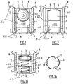
- the hollow body for example essentially cylindrical in shape, at least partially defines a chamber 100 provided with an inlet 5 and an outlet 6.
- the shutter 2 is movable relative to the hollow body 1 between a rest position for example illustrated in figures 1, 2, 3a , 4 , 6a, 6b, 7a (dotted line), 8a, 8e, 9b and 10a, and an extreme position for example illustrated in figures 6c, 7b , 8b, 8c , 9a and 10c , which is distant from the rest position.
- the shutter 2 is biased towards its rest position by a return force, and biased towards its extreme position, during the application of a differential pressure between the inlet 5 of the chamber and the outlet 6 of this chamber, by the fluid circulating from the upstream space E1 to the downstream space E2, the upstream space E1 extending at least outside the chamber 100 on the side of its inlet 5, and the downstream space E2 s' extending at least outside the device and the chamber 100 on the side of its outlet 6.
- the container or bottle 8 In its conventional rest position, the container or bottle 8 is placed vertically so that its neck 80 faces downwards, the fluid to be dispensed therefore having a spontaneous tendency to flow out by gravity from the space. upstream E1 to the downstream space E2, and from the inlet 5 of the chamber 100 to the outlet 6 of this chamber.
- the shutter 2 isolates the upstream space E1 and the downstream space E2 from each other in its extreme position, and only in this position.
- outlet 6 of the chamber 100 communicates with the upstream space E1 for any position of the shutter 2 other than its extreme position.
- the shutter 2 can for example fulfill its function by cooperating with a sealing seat 30 which surrounds a fluid passage arranged between the upstream space E1 and the downstream space E2, and on which this shutter 2 rests in its extreme position.
- the device of the invention may comprise a plug 3 inserted into the hollow body 1, this plug being pierced with a flow orifice forming the outlet 6 of the chamber 100.
- the figures 1 to 5b illustrate embodiments in which the shutter 2 has an average density lower than that of the fluid to be distributed, and typically a density lower than one.
- the shutter 2 when it is bathed in the fluid to be distributed, behaves like a float, so that the return force which urges this shutter towards its rest position is at least partially constituted by the force d 'Archimedes exercising on him.
- container or flask 8 will be considered to be oriented so that its neck 80 faces downward.
- the hollow body for example of cylindrical shape and made of plastic material, contains, as shutter 2, a hollow and spherical float.
- This hollow body 1 is forcibly inserted into the neck 80 of the container 8 containing the fluid to be dosed until a stop 9 of this body 1 comes into contact against this neck.
- a plug 3 is forcibly inserted into the lower part of the hollow body 1 until a stop 7 of this plug 3 comes into contact against this body 1.
- the inlet 5 of the chamber 100 takes the form of an orifice formed in the hollow body 1, and the outlet 6 of the chamber 100 takes the form of an orifice formed in the stopper 3.
- the size and / or the shape of the outlet of the fluid chamber 6 can thus be modified at will by replacing the stopper 3 inserted in the neck 80 by another stopper 3 having a flow orifice 6 of size and / or different shape.
- Two grooves 4, for example U-shaped and arranged at 90 ° to each other, are made in the upper part of the hollow body 1 in order to prevent the float 2 from sealing the inlet opening 5. of the chamber 100, which is located in the upper part of the hollow body 1.
- the edge of the recessed portion of the plug 3 forms a sealing seat 30 allowing the float 2, when it comes to bear on this seat 30 in its extreme position under the effect of an increase in the pressure of the fluid in the 'upstream space E1, to isolate this upstream space E1 from the downstream space E2, and to interrupt the flow of fluid through the calibrated orifice 6 of the outlet of the chamber 100.
- the annular clearance between the hollow body 1 and the float 2 is dimensioned so as to allow a flow by gravity of the fluid under the float 2.
- the differential pressure necessary for the displacement of the float 2 provision should be made for the passage section of the outlet orifice 6 of the chamber 100 to be greater than the passage section offered by the annular clearance between the float 2 and the hollow body 1.
- the flexible bottle 8 can thus return to its rest position, and the fluid, which flows by gravity in the hollow body 1, gradually rises the float 2 in the high position towards its rest position, by the action of the thrust. of Archimedes.
- the figure 2 illustrates an embodiment which does not differ from the embodiment of the figure 1 that by the fact that the shutter 2 takes the form of a cylindrical float 2 provided with a frustoconical upper part instead of taking the form of a spherical float.
- this cylindrical float with a frustoconical head has a larger volume than the spherical float, the embodiment of the figure 2 is more particularly suitable for the dosage of fluids of low density.
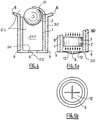
- a helical spring 10 prestressed in compression is arranged between the bottom of the plug 3 and the float 2, this float 2 thus being urged towards its rest position, in abutment against the upper wall of the hollow body 1 at the level of the orifice d 'input 5, by a return force comprising both the Archimedean force exerted on the float 2 by the fluid, and the elastic force exerted on the float 2 by the spring 10.
- the elastic force exerted by the spring 10 on the float 2 is dimensioned to compensate only for the weight of the float 2, the spring 10 serving only to promote the rise of the float 2 when the fluid flows in the lower part of the hollow body 1.
- This arrangement which easily allows to overcome viscous friction, is more particularly suited to the case where the fluid to be distributed has a high viscosity.
- the figure 3b illustrates a variant of the embodiment of the figure 3a , likely to be implemented in the case illustrated in figure 3a and in which the float 2 has an upper part of frustoconical shape.
- the upper part of the float 2 comprises several circular notches 13 cut over the entire cylindrical height of the float 2, so that the fluid can flow from the bottle 8 to the chamber 100 when the float 2 is in its position. rest.
- these notches 13 are dimensioned in such a way that the float 2 remains capable of closing off the sealing seat 30 as soon as it reaches its extreme position.
- the minimum diameter of the cylindrical surface of the float 2, at the places most hollowed out by the notches 13, is greater than the diameter of the internal surface of the plug 3.
- the area of the annular section defined between the float 2 and the inside of the hollow body 1 remains less than the area of the outlet orifice 6 of the chamber 100, made in the plug 3.
- the figure 4 shows an embodiment of a metering device without a stopper and in which the hollow body 1 is forcibly inserted into the neck 80 of the flexible bottle containing the fluid until a stop 9 of the hollow body rests on the neck 80. Due to the absence of a plug, the outlet orifice 6 of the chamber 100 is directly formed in the base of the hollow body 1. The sealing seat 30 is then directly formed by the edge of the orifice 6, on which the shutter 2 is applied in a sealed manner in its extreme position. The upper part of the cylindrical hollow body 1 is fully open.
- the insertion of the float 2 under the semi-rigid tongue 11, or the withdrawal of this float can only be obtained by applying to the tongue 11 a deformation greater than that which this tongue undergoes in the normal use of the dosing device.
- a pressure exerted on the bottle 8 drives the fluid contained in the latter towards the neck 80.
- the moving fluid exerts a pressure on the float 2, which moves downwards by expelling, through the outlet orifice 6, the fluid. contained in the chamber 100.
- this orifice is closed and the flow of fluid out of the chamber 100 and towards the downstream space E2 is interrupted.
- Releasing the pressure on the surface of the bottle 8 produces a vacuum which has the effect of bringing air into the hollow body 1, returning the bottle to its resting state.
- the semi-rigid material constituting the tongue 11 is chosen sufficiently flexible to be able to undergo without breaking the deformation necessary for the forceful insertion of the float 2 into the hollow body 1, but sufficiently rigid not to be subjected, under the effect of the Archimedean force exerted on the float 2, deformation which would allow this float to escape from the hollow body from its rest position in which it rests on this tongue.
- the embodiment of the figure 4 makes it possible to manufacture the metering device in two molded parts, namely the main body 1 and the tongue 11 on the one hand, and the float 2 on the other hand.
- the figures 5a and 5b illustrate an alternative embodiment particularly applicable to the embodiment of the figure 4 and particularly suitable for the case where the fluid to be dosed has a relatively low viscosity.
- the outlet of the chamber 6 is pierced in an elastically deformable wall and has a passage section that reversibly increases under the effect of the pressure of the fluid.
- the bottom 12 of the hollow body, in which the flow orifice 6 constituting the outlet of the chamber 100 is formed, is made of an elastically deformable material having a cruciform cutout, and the shutter 2 has a cylindrical shape.
- the float 2 closes the outlet 6 and prevents any flow of fluid. Without external pressure, the only force generated by the height of the fluid in the bottle cannot overcome the elasticity of the flexible strips formed at the corners of the cruciform outlet 6 of the chamber 100, the fluid therefore being retained in the metering device.
- the passage section of the bottom 12 in the rest state does not allow the flow of fluid from the bottle but allows, after release of the pressure on the bottle, to bring the air into the latter to allow the bottle to regain its initial position.
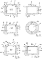
- the figures 6a to 10d illustrate other possible embodiments in which the shutter 2 has a density that is a priori arbitrary and in any case not necessarily less than that of the fluid, this shutter being urged towards its rest position by a return force of only elastic nature .
- the shutter 2 is constituted by a diaphragm movable in translation relative to the hollow body 1, this diaphragm being connected to the hollow body 1 by two elastic tongues 21 diametrically opposed to each other, and the elastic restoring force of the shutter being exerted by these tongues 21.
- the hollow body 1, the shutter 2 and each of the elastic tongues 21 are preferably made in one piece from an elastic material.
- the sealing seat 30, on which the shutter 2 rests in its extreme position, is formed on the upper part of the hollow body 1 and surrounds a fluid passage arranged between the upstream space E1 and the downstream space E2 and forming the entrance 5 of the chamber 100.
- shutter 2 occupies the position shown in figures 6a and 6b .
- the fluid which passes through the hollow body 1 under the effect of an increase in the pressure at the inlet 5 of the chamber 100 drives the shutter 2 from its rest position ( figure 6a ) up to its extreme position ( figure 6c ), and the volume of fluid distributed between the moment when the shutter 2 leaves its rest position and the moment when this shutter 2 reaches its extreme position is equal to the volume of fluid whose flow is necessary to effect this displacement shutter 2.
- FIG. 7a and 7b differs from the embodiment of figures 6a to 6d that by the fact that the shutter 2 is attached to the hollow body 1 by a single elastic tongue 21, this shutter being shown in its rest position in dotted lines on the figure 7a and in its extreme position on the figure 7b .
- FIG. 8a to 8f illustrates the invention and uses the same shutter 2 as the embodiment of figures 6a to 6d , as well as a plug 3 inserted in the hollow body 1 and carrying the outlet orifice 6, as is the case in the embodiments of figures 1, 2 and 3a especially.
- the embodiment of figures 8a to 8f further comprises a piston 14 and a spring 15.
- the piston 14 is slidably mounted in the hollow body 1 and the shutter 2 is carried by the piston 14 by means of two resilient tongues 21 in the same way that it was carried by the hollow body 1 in the embodiment of figures 6a to 6d .
- the piston 14 has an essentially annular shape ( figure 8f ) defining a sealing seat 30 around a fluid passage which constitutes the inlet 5 of the chamber 100 and which allows selective communication between the upstream space E1 and the downstream space E2.
- the spring 15 is for its part prestressed in compression and disposed between the stopper 3 and the piston 14, so that it tends to give the chamber 100 a maximum volume.
- a stop 140 is formed on the internal periphery of the hollow body 1 to limit the stroke of the piston 14 upwards by defining a maximum high position of this piston in the hollow body 1.
- the figure 8a illustrates this device in its stable rest configuration, in which the outlet 6 of the chamber 100 communicates with the inlet 5 of this chamber.
- the increase in the pressure in the bottle 8 causes the displacement of the shutter 2 towards its extreme position illustrated on figure 8b , and in which this shutter closes the inlet 5 of the chamber 100 by pressing on the seat of the valve 30.
- the embodiment of figures 8a to 8f therefore makes it possible to distribute a volume of fluid comprising, in addition to the volume of fluid dispensed while the shutter passes from its rest position to its extreme position, an additional volume of fluid very exactly equal to the difference between the maximum volume of the room 100, shown in figures 8a and 8e , and the minimum volume of this chamber, shown in figure 8c .
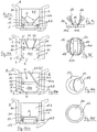
- the chamber is partially delimited by a plug 3 inserted in the hollow body 1, and the latter comprises an internal peripheral stop 140 making it possible to limit the stroke of the piston 14 upwards.
- the piston 14 essentially comprises two mutually transverse beams 141 and 142, in particular visible on the figure 9d , and the shutter 2 is formed of two flaps 22 articulated on the beam 142 by means of respective elastic tongues 21 forming hinges, these flaps 22 being symmetrical to one another with respect to the median plane of the beam 142 and of the hollow cylindrical body 1.
- the piston 14, each of the flaps 22 forming the shutter 2, and each of the elastic tabs 21 forming the hinges are made in one piece from an elastic material.
- FIG. 9a differs from all of the other embodiments presented by the fact that the shutter 2, in its extreme position as shown in figure 9a , isolates the upstream E1 and downstream E2 spaces from one another not by resting in a fixed manner on a sealing seat, but thanks to a sliding support of the edge of each of the flaps 22 on the internal cylindrical wall of the hollow body 1.
- the shutter 2 is formed of a single flap 23, articulated on the piston 14 by means of a single elastic tongue 21.
- the embodiment of figures 10a to 10d differs essentially from the embodiment of figures 8a to 8f in that the shutter 2 is constituted by a flap 23 movable in rotation and not by a diaphragm movable in translation.
- the piston 14, the flap 23 forming the shutter 2, and the elastic tongue 21 forming a hinge are made in one piece from an elastic material.
- the piston 14 of the embodiment of figures 10a to 10d has an essentially annular shape defining a sealing seat 30 around a fluid passage which constitutes the inlet 5 of the chamber 100 and which allows selective communication between the upstream space E1 and the downstream space E2.
Landscapes
- Physics & Mathematics (AREA)
- Fluid Mechanics (AREA)
- General Physics & Mathematics (AREA)
- Engineering & Computer Science (AREA)
- Mechanical Engineering (AREA)
- Containers And Packaging Bodies Having A Special Means To Remove Contents (AREA)
- Closures For Containers (AREA)
- Self-Closing Valves And Venting Or Aerating Valves (AREA)
- Feeding, Discharge, Calcimining, Fusing, And Gas-Generation Devices (AREA)
- Measuring Fluid Pressure (AREA)
Claims (3)
- Dosiervorrichtung zum Übertragen eines vorbestimmten Volumens eines flüssigen oder pastösen Fluids von einem stromaufwärtigen Raum (E1) zu einem stromabwärtigen Raum (E2), in Reaktion auf einen Druckanstieg des Fluids im stromaufwärtigen Raum (E1),
wobei die Vorrichtung wenigstens einen Hohlkörper (1), einen Verschluss (2) und einen Dichtungssitz (30) umfasst, der an einem ringförmigen Element (14) definiert ist und einen Fluid-Durchgang umgibt, der zwischen dem stromaufwärtigen Raum (E1) und dem stromabwärtigen Raum (E2) angeordnet ist,
wobei der Hohlkörper zumindest teilweise eine Kammer (100) begrenzt, die mit einem Einlass (5) und einem Auslass (6) versehen ist,
wobei der Verschluss (2) in Bezug auf das ringförmige Element (14) beweglich ist zwischen einer Ruheposition, zu welcher der Verschluss (2) durch eine Rückstellkraft gedrängt wird, die zumindest teilweise durch eine elastische Rückstellkraft gebildet ist, und einer Extremposition, die von der Ruheposition entfernt ist, zu welcher der Verschluss (2) selektiv durch das Fluid gedrängt wird, das vom stromaufwärtigen Raum (E1) zum stromabwärtigen Raum (E2) fließt, wobei sich der Verschluss in der Extremposition an dem Dichtungssitz abstützt,
wobei sich der stromaufwärtige Raum (E1) wenigstens außerhalb der Kammer (100) auf der Seite ihres Einlasses (5) erstreckt, und wobei der stromabwärtige Raum (E2), sich wenigstens außerhalb der Vorrichtung und der Kammer (100) auf der Seite ihres Auslasses (6) erstreckt,
wobei der Verschluss (2) in seiner Extremposition und nur in dieser Position den stromaufwärtigen Raum (E1) und den stromabwärtigen Raum (E2) voneinander isoliert, und wobei der Auslass (6) der Kammer (100) mit dem stromaufwärtigen Raum (E1) für jede Position des Verschlusses (2) außer seiner Extremposition in Verbindung steht,
wobei der Verschluss (2) eine Membran aufweist, die relativ zum ringförmigen Element (14) durch Translation beweglich ist, und wenigstens eine elastische Zunge (21), die den Verschluss (2) mit dem ringförmigen Element (14) verbindet, wobei das ringförmige Element (14), der Verschluss (2) und jede elastische Zunge (21) einstückig aus einem elastischen Material hergestellt sind, und wobei die Rückstellkraft von jeder elastischen Zunge (21) ausgeübt wird,
dadurch gekennzeichnet, dass sie weiter einen Stopfen (3) umfasst, der in den Hohlkörper (1) eingesetzt ist, wobei der Stopfen von einer Strömungsöffnung durchbohrt ist, die den Auslass (6) der Kammer (100) bildet,
und dadurch, dass sie ferner einen Kolben (14) und eine Feder (15) umfasst, dass der Kolben (14) verschiebbar in dem Hohlkörper (1) montiert ist und den Verschluss (2) trägt, und dass die Feder (15) unter Druck vorgespannt und zwischen dem Stopfen (3) und dem Kolben (14) angeordnet ist, und dass das ringförmige Element durch den Kolben (14) gebildet ist. - Dosiervorrichtung nach Anspruch 1, dadurch gekennzeichnet, dass sie zwei diametral einander gegenüberliegende elastische Zungen (21) umfasst.
- Dosiervorrichtung nach einem der vorhergehenden Ansprüche, dadurch gekennzeichnet, dass sie ferner einen Behälter (8) umfasst, der mit einem Hals (80) versehen ist, wobei der Behälter dazu geeignet ist, das Fluid aufzunehmen, und er einen stromaufwärtigen Raum (E1) mit variablem Volumen abgrenzt, wobei der Druckanstieg des Fluids durch Verringerung des Volumens des stromaufwärtigen Raums (E1) erhalten wird, und dadurch, dass der Hohlkörper (1) in dichter Weise im Hals (80) des Behälters (8) angeordnet ist.
Priority Applications (1)
| Application Number | Priority Date | Filing Date | Title |
|---|---|---|---|
| EP14157367.5A EP2746733B1 (de) | 2008-11-05 | 2009-11-04 | Dosiervorrichtung mit Differenzialdruck |
Applications Claiming Priority (2)
| Application Number | Priority Date | Filing Date | Title |
|---|---|---|---|
| FR0806164A FR2938057B1 (fr) | 2008-11-05 | 2008-11-05 | Doseur a delta de pression |
| PCT/FR2009/001277 WO2010052390A1 (fr) | 2008-11-05 | 2009-11-04 | Dispositif doseur a pression differentielle |
Related Child Applications (2)
| Application Number | Title | Priority Date | Filing Date |
|---|---|---|---|
| EP14157367.5A Division EP2746733B1 (de) | 2008-11-05 | 2009-11-04 | Dosiervorrichtung mit Differenzialdruck |
| EP14157367.5A Division-Into EP2746733B1 (de) | 2008-11-05 | 2009-11-04 | Dosiervorrichtung mit Differenzialdruck |
Publications (2)
| Publication Number | Publication Date |
|---|---|
| EP2342542A1 EP2342542A1 (de) | 2011-07-13 |
| EP2342542B1 true EP2342542B1 (de) | 2020-09-16 |
Family
ID=40852651
Family Applications (2)
| Application Number | Title | Priority Date | Filing Date |
|---|---|---|---|
| EP14157367.5A Active EP2746733B1 (de) | 2008-11-05 | 2009-11-04 | Dosiervorrichtung mit Differenzialdruck |
| EP09784338.7A Active EP2342542B1 (de) | 2008-11-05 | 2009-11-04 | Differenzdruck-dosiereinrichtung |
Family Applications Before (1)
| Application Number | Title | Priority Date | Filing Date |
|---|---|---|---|
| EP14157367.5A Active EP2746733B1 (de) | 2008-11-05 | 2009-11-04 | Dosiervorrichtung mit Differenzialdruck |
Country Status (8)
| Country | Link |
|---|---|
| US (3) | US8997788B2 (de) |
| EP (2) | EP2746733B1 (de) |
| JP (2) | JP2012507451A (de) |
| CA (2) | CA2909853C (de) |
| DE (1) | DE202009019069U1 (de) |
| ES (1) | ES2743053T3 (de) |
| FR (1) | FR2938057B1 (de) |
| WO (1) | WO2010052390A1 (de) |
Families Citing this family (22)
| Publication number | Priority date | Publication date | Assignee | Title |
|---|---|---|---|---|
| FR2938057B1 (fr) | 2008-11-05 | 2013-05-17 | Patrick Wozna | Doseur a delta de pression |
| EP2390009A1 (de) * | 2010-05-31 | 2011-11-30 | Scandinavian Amenities A/S | Messvorrichtung zur Ausgabe von abgemessenen Flüssigkeitsmengen aus einem verformbaren Behälter |
| WO2012171708A1 (en) * | 2011-06-17 | 2012-12-20 | Unilever Plc | Dispenser cap |
| EP2850660A1 (de) | 2012-05-17 | 2015-03-25 | General Electric Company | Halbleiterbauelement mit verbindungsabschlusserweiterung |
| US11185562B2 (en) | 2013-02-04 | 2021-11-30 | Seres Therapeutics, Inc. | Compositions and methods for inhibition of pathogenic bacterial growth |
| GB201403942D0 (en) * | 2014-03-06 | 2014-04-23 | Obrist Closures Switzerland | A dosing device |
| DE102014206568A1 (de) * | 2014-04-04 | 2015-10-08 | Aptar Radolfzell Gmbh | Dosiereinrichtung für einen Flüssigkeitsspender und Flüssigkeitsspender mit einer solchen |
| US10071836B2 (en) * | 2014-04-16 | 2018-09-11 | Reckitt Benckiser (Brands) Limited | Dosing dispensing closure |
| EP3088851A1 (de) | 2015-04-28 | 2016-11-02 | Aptar Freyung GmbH | Flüssigkeitsdosiervorrichtung |
| MX2017002769A (es) * | 2014-09-04 | 2017-09-28 | Aptar Freyung Gmbh | Dispositivo dosificador de liquido. |
| EP2993447A1 (de) | 2014-09-04 | 2016-03-09 | Aptar Freyung GmbH | Flüssigkeitsdosiervorrichtung |
| JP6478564B2 (ja) * | 2014-11-06 | 2019-03-06 | 東京ライト工業株式会社 | 注出栓 |
| EP3023752A1 (de) | 2014-11-18 | 2016-05-25 | Aptar Radolfzell GmbH | Flüssigkeitsspender und Austragkopf hierfür |
| EP3035009A1 (de) | 2014-12-18 | 2016-06-22 | Aptar Radolfzell GmbH | Flüssigkeitsspender und Indikatoreinrichtung |
| NL2014031B1 (en) * | 2014-12-22 | 2016-10-12 | Plasticum Netherlands B V | Dosing cap. |
| US10365140B2 (en) * | 2015-06-29 | 2019-07-30 | Silgan Dispensing Systems Netherlands B.V. | Measured dose dispensers and methods of using same |
| WO2017182972A1 (en) | 2016-04-19 | 2017-10-26 | Flexidose | Dosing dispenser |
| WO2018200926A1 (en) * | 2017-04-27 | 2018-11-01 | Illinois Tool Works Inc. | Flexible ball valve for liquid metering and dispensing |
| WO2022236219A1 (en) * | 2021-04-20 | 2022-11-10 | Flexpenser Ab | Dosing applicator for medical and non-medical containers |
| FR3130770B1 (fr) | 2021-12-17 | 2023-12-08 | Aptar France Sas | Dispositif doseur de fluide |
| US11904330B2 (en) * | 2022-02-28 | 2024-02-20 | L'oreal | Cosmetic dispenser with accordion bladder valve system |
| US11860017B2 (en) | 2022-02-28 | 2024-01-02 | L'oreal | Cosmetic dispenser with bladder valve system |
Citations (1)
| Publication number | Priority date | Publication date | Assignee | Title |
|---|---|---|---|---|
| JPS5041946U (de) * | 1973-08-08 | 1975-04-28 |
Family Cites Families (39)
| Publication number | Priority date | Publication date | Assignee | Title |
|---|---|---|---|---|
| US2970722A (en) * | 1958-07-07 | 1961-02-07 | Gadget Of The Month Club Inc | Pressure seal for pressurized liquid container |
| US3567079A (en) | 1968-08-08 | 1971-03-02 | Cleone H Weigand | Dispenser container with metering neck |
| SE381336B (sv) | 1972-12-15 | 1975-12-01 | B Nilson | Doseringsanordning for fluider |
| JPS5727122B2 (de) | 1973-08-20 | 1982-06-09 | ||
| JPS5274164U (de) * | 1975-11-29 | 1977-06-02 | ||
| JPS5274164A (en) | 1975-12-16 | 1977-06-21 | Nippon Steel Corp | Screening by vibrating strainers |
| US4049162A (en) | 1976-03-05 | 1977-09-20 | Yule Lance S | Metering valve |
| SE413623B (sv) | 1978-03-22 | 1980-06-16 | Kenova Ab | Anordning for portionsvis utmatning av vetska fran en behallare |
| US4215724A (en) * | 1978-03-17 | 1980-08-05 | The Logsdon Foundation | Backflow preventer for sewer system |
| DE3308013A1 (de) | 1983-03-07 | 1984-09-13 | Henkel KGaA, 4000 Düsseldorf | Dosiervorrichtung |
| US5078305A (en) | 1989-11-24 | 1992-01-07 | Delta Dispensing, Inc. | Simultaneous fill-dispense invert dispenser container |
| US5046526A (en) | 1990-11-28 | 1991-09-10 | Morley Longmore | One-way check valve |
| SE501000C2 (sv) * | 1992-02-03 | 1994-10-17 | Jana System Ab | Utportioneringsanordning för flytande substanser |
| DE4305390C1 (de) | 1993-02-22 | 1994-01-27 | Design Udo Suffa Gmbh S | Flüssigkeitsbehälter mit aufgesetzter Dosierkammer |
| DE19700607A1 (de) | 1996-11-19 | 1998-05-20 | Elvira Ahrens | Variabler Dosierkopf |
| NL1009549C2 (nl) | 1997-08-01 | 1999-02-02 | Sara Lee De Nv | Samenstel voorzien van een flexibele houder met een doseerinrichting en een doseerinrichting van een dergelijk samenstel. |
| US6068165A (en) | 1998-09-02 | 2000-05-30 | Minihane; Denis A. | Premeasured dispensing bottle cap |
| FR2784968B1 (fr) | 1998-10-23 | 2000-12-01 | Oreal | Embout doseur et recipient equipe d'un embout doseur selon l'invention |
| NL1010749C2 (nl) | 1998-12-07 | 2000-06-08 | V O F Pharmasept | Houder voor het gedoseerd en in hoofdzaak kiemvrij afgeven van een vloeistof. |
| JP3068076U (ja) | 1999-10-08 | 2000-04-21 | 健一 若林 | 滴下容器 |
| WO2003025520A1 (en) | 2001-09-12 | 2003-03-27 | Anthony Charles Lammond Wass | Improved liquid dosing device |
| US6662973B1 (en) * | 2002-07-02 | 2003-12-16 | Stephen P. Velliquette | Fluid flow control valve/seal for fluid dispensers |
| US7494028B2 (en) | 2003-10-15 | 2009-02-24 | Zavida Coffee Company Inc. | Fluid dispensing system suitable for dispensing liquid flavorings |
| JP2005138900A (ja) | 2003-10-16 | 2005-06-02 | Daipura Kk | 液体充填用容器 |
| JP2006334537A (ja) * | 2005-06-03 | 2006-12-14 | Nitto Denko Corp | 通気部材および通気部材キットならびにこれらを用いた通気筐体および通気タンク |
| JP2007069931A (ja) | 2005-09-06 | 2007-03-22 | Nisshin Kagaku Kk | 内容物の収納容器 |
| US7726520B2 (en) | 2005-12-22 | 2010-06-01 | Innopak Inc. | Metered dispenser with feed-containing piston drive mechanism |
| ES2738048T3 (es) | 2007-06-08 | 2020-01-20 | Diversey Inc | Aparato y método de dispensación de fluidos |
| US8136701B2 (en) | 2008-09-23 | 2012-03-20 | Prince Castle, LLC | Fixed-volume liquid dispenser |
| FR2938057B1 (fr) | 2008-11-05 | 2013-05-17 | Patrick Wozna | Doseur a delta de pression |
| US8464904B2 (en) | 2009-04-17 | 2013-06-18 | James M. Woodruff | Methods and containers for reducing spillage and residual liquid when pouring liquid out of a container |
| US8434647B2 (en) | 2009-08-08 | 2013-05-07 | Riad Aamar | Device for measuring and dispensing a prescribed amount of liquid |
| US8356731B2 (en) * | 2009-09-09 | 2013-01-22 | Mtn Products Inc | Energy saving baffle for water cooler |
| BR112012005984A2 (pt) | 2009-09-18 | 2016-03-15 | Procter & Gamble | aparelho para dispensar dose unitária |
| JP5847796B2 (ja) | 2010-03-17 | 2016-01-27 | アイピーエヌ アイピー ビー.ブイ. | ディスペンサ装置付き容器 |
| EP2390009A1 (de) | 2010-05-31 | 2011-11-30 | Scandinavian Amenities A/S | Messvorrichtung zur Ausgabe von abgemessenen Flüssigkeitsmengen aus einem verformbaren Behälter |
| BR112013002780A2 (pt) | 2010-08-06 | 2016-06-07 | Unilever Nv | tampa de distribuição e recipiente para conter um líquido |
| EP2637800B1 (de) | 2010-11-09 | 2015-08-26 | Unilever N.V. | Dosierkappe für behälter |
| WO2012171708A1 (en) | 2011-06-17 | 2012-12-20 | Unilever Plc | Dispenser cap |
-
2008
- 2008-11-05 FR FR0806164A patent/FR2938057B1/fr active Active
-
2009
- 2009-11-04 ES ES14157367T patent/ES2743053T3/es active Active
- 2009-11-04 US US13/127,972 patent/US8997788B2/en active Active
- 2009-11-04 CA CA2909853A patent/CA2909853C/fr active Active
- 2009-11-04 CA CA2742898A patent/CA2742898C/fr active Active
- 2009-11-04 WO PCT/FR2009/001277 patent/WO2010052390A1/fr active Application Filing
- 2009-11-04 EP EP14157367.5A patent/EP2746733B1/de active Active
- 2009-11-04 EP EP09784338.7A patent/EP2342542B1/de active Active
- 2009-11-04 JP JP2011533786A patent/JP2012507451A/ja active Pending
- 2009-11-04 DE DE202009019069.2U patent/DE202009019069U1/de not_active Expired - Lifetime
-
2013
- 2013-12-06 JP JP2013253642A patent/JP2014111476A/ja active Pending
-
2014
- 2014-02-25 US US14/189,605 patent/US9446886B2/en active Active
-
2016
- 2016-01-19 US US15/000,804 patent/US20160138954A1/en not_active Abandoned
Patent Citations (1)
| Publication number | Priority date | Publication date | Assignee | Title |
|---|---|---|---|---|
| JPS5041946U (de) * | 1973-08-08 | 1975-04-28 |
Also Published As
| Publication number | Publication date |
|---|---|
| US20140183230A1 (en) | 2014-07-03 |
| EP2342542A1 (de) | 2011-07-13 |
| EP2746733B1 (de) | 2019-05-29 |
| US9446886B2 (en) | 2016-09-20 |
| CA2909853A1 (fr) | 2010-05-14 |
| JP2012507451A (ja) | 2012-03-29 |
| JP2014111476A (ja) | 2014-06-19 |
| WO2010052390A1 (fr) | 2010-05-14 |
| CA2742898A1 (fr) | 2010-05-14 |
| DE202009019069U1 (de) | 2016-03-10 |
| US20110277857A1 (en) | 2011-11-17 |
| EP2746733A1 (de) | 2014-06-25 |
| US8997788B2 (en) | 2015-04-07 |
| FR2938057B1 (fr) | 2013-05-17 |
| US20160138954A1 (en) | 2016-05-19 |
| CA2909853C (fr) | 2016-12-06 |
| FR2938057A1 (fr) | 2010-05-07 |
| ES2743053T3 (es) | 2020-02-18 |
| CA2742898C (fr) | 2016-01-19 |
Similar Documents
| Publication | Publication Date | Title |
|---|---|---|
| EP2342542B1 (de) | Differenzdruck-dosiereinrichtung | |
| EP0954485B1 (de) | Vorrichtung zur abgabe vom fliessfähigen produkt mit verschlussvorrichtung | |
| EP0307310B1 (de) | Zerstaüber mit Vordruck-Handpumpe für die Benutzung mit einem Treibgas | |
| EP1185376B1 (de) | Abgabevorrichtung für medien | |
| EP1572375B1 (de) | Manuell betätigte dosierpumpe | |
| WO1995025945A1 (fr) | Dispositif doseur destine a delivrer des doses unitaires constantes | |
| EP3417947B1 (de) | Dosiervorrichtung zur ausstattung eines behälters, und behälter, der eine solche vorrichtung umfasst | |
| EP2906484B1 (de) | Dosierventil zur abgabe eines aerosols | |
| EP2229239A1 (de) | Pumpe zur ausgabe eines flüssigen oder zähflüssigen produkts | |
| EP0821775B1 (de) | Konstruktion eines einlassventils | |
| EP1914006A2 (de) | Pumpe mit Entlüftungsmitteln | |
| FR2817244A1 (fr) | Dispositif ameliore pour le conditionnement et la distribution dosee d'un produit liquide | |
| FR2746676A1 (fr) | Dispositif de distribution d'une dose unique de produit fluide | |
| EP0312474A1 (de) | Automatischer Spender für pastöse Massen | |
| FR2528122A1 (fr) | Pompe pour vaporisateur toutes positions | |
| EP0377536A1 (de) | Rückschlagventil zum Zuführen einer Spritzflüssigkeit zu einer Pumpkammer und dessen Verwendung | |
| EP1328351B1 (de) | Ausgabepumpe für medien | |
| EP0270409B1 (de) | Behälter zum Dosieren von Behandlungsflüssigkeit | |
| FR2767311A1 (fr) | Systeme d'obturation et dispositif de distribution de produit fluide comportant un tel systeme | |
| EP3271580A1 (de) | Manuelle pumpe | |
| EP3352913B1 (de) | Airless spender mit einer pumpe | |
| FR2594419A1 (fr) | Procede pour distribuer une substance visqueuse par doses successives et conditionnement pour sa mise en oeuvre | |
| FR2786467A1 (fr) | Dispositif de distribution de produits liquides, fluides ou pateux | |
| EP2874757B1 (de) | Flüssigproduktspender | |
| EP3634883B1 (de) | Dosierventil und fluidproduktabgabevorrichtung mit solch einem ventil |
Legal Events
| Date | Code | Title | Description |
|---|---|---|---|
| PUAI | Public reference made under article 153(3) epc to a published international application that has entered the european phase |
Free format text: ORIGINAL CODE: 0009012 |
|
| 17P | Request for examination filed |
Effective date: 20110420 |
|
| AK | Designated contracting states |
Kind code of ref document: A1 Designated state(s): AT BE BG CH CY CZ DE DK EE ES FI FR GB GR HR HU IE IS IT LI LT LU LV MC MK MT NL NO PL PT RO SE SI SK SM TR |
|
| AX | Request for extension of the european patent |
Extension state: AL BA RS |
|
| DAX | Request for extension of the european patent (deleted) | ||
| RAP1 | Party data changed (applicant data changed or rights of an application transferred) |
Owner name: FLEXIDOSE |
|
| RIN1 | Information on inventor provided before grant (corrected) |
Inventor name: WOZNA, PATRICK |
|
| 17Q | First examination report despatched |
Effective date: 20140917 |
|
| 17Q | First examination report despatched |
Effective date: 20141105 |
|
| STAA | Information on the status of an ep patent application or granted ep patent |
Free format text: STATUS: EXAMINATION IS IN PROGRESS |
|
| REG | Reference to a national code |
Ref country code: DE Ref legal event code: R079 Ref document number: 602009062775 Country of ref document: DE Free format text: PREVIOUS MAIN CLASS: G01F0011280000 Ipc: G01F0011040000 |
|
| RIC1 | Information provided on ipc code assigned before grant |
Ipc: B05B 11/02 20060101ALN20200302BHEP Ipc: B05B 11/04 20060101ALI20200302BHEP Ipc: G01F 11/04 20060101AFI20200302BHEP Ipc: G01F 11/28 20060101ALI20200302BHEP |
|
| GRAP | Despatch of communication of intention to grant a patent |
Free format text: ORIGINAL CODE: EPIDOSNIGR1 |
|
| STAA | Information on the status of an ep patent application or granted ep patent |
Free format text: STATUS: GRANT OF PATENT IS INTENDED |
|
| INTG | Intention to grant announced |
Effective date: 20200416 |
|
| GRAS | Grant fee paid |
Free format text: ORIGINAL CODE: EPIDOSNIGR3 |
|
| GRAA | (expected) grant |
Free format text: ORIGINAL CODE: 0009210 |
|
| STAA | Information on the status of an ep patent application or granted ep patent |
Free format text: STATUS: THE PATENT HAS BEEN GRANTED |
|
| AK | Designated contracting states |
Kind code of ref document: B1 Designated state(s): AT BE BG CH CY CZ DE DK EE ES FI FR GB GR HR HU IE IS IT LI LT LU LV MC MK MT NL NO PL PT RO SE SI SK SM TR |
|
| REG | Reference to a national code |
Ref country code: GB Ref legal event code: FG4D Free format text: NOT ENGLISH |
|
| REG | Reference to a national code |
Ref country code: CH Ref legal event code: EP |
|
| REG | Reference to a national code |
Ref country code: DE Ref legal event code: R096 Ref document number: 602009062775 Country of ref document: DE |
|
| REG | Reference to a national code |
Ref country code: IE Ref legal event code: FG4D Free format text: LANGUAGE OF EP DOCUMENT: FRENCH |
|
| REG | Reference to a national code |
Ref country code: AT Ref legal event code: REF Ref document number: 1314564 Country of ref document: AT Kind code of ref document: T Effective date: 20201015 |
|
| PG25 | Lapsed in a contracting state [announced via postgrant information from national office to epo] |
Ref country code: GR Free format text: LAPSE BECAUSE OF FAILURE TO SUBMIT A TRANSLATION OF THE DESCRIPTION OR TO PAY THE FEE WITHIN THE PRESCRIBED TIME-LIMIT Effective date: 20201217 Ref country code: NO Free format text: LAPSE BECAUSE OF FAILURE TO SUBMIT A TRANSLATION OF THE DESCRIPTION OR TO PAY THE FEE WITHIN THE PRESCRIBED TIME-LIMIT Effective date: 20201216 Ref country code: FI Free format text: LAPSE BECAUSE OF FAILURE TO SUBMIT A TRANSLATION OF THE DESCRIPTION OR TO PAY THE FEE WITHIN THE PRESCRIBED TIME-LIMIT Effective date: 20200916 Ref country code: HR Free format text: LAPSE BECAUSE OF FAILURE TO SUBMIT A TRANSLATION OF THE DESCRIPTION OR TO PAY THE FEE WITHIN THE PRESCRIBED TIME-LIMIT Effective date: 20200916 Ref country code: SE Free format text: LAPSE BECAUSE OF FAILURE TO SUBMIT A TRANSLATION OF THE DESCRIPTION OR TO PAY THE FEE WITHIN THE PRESCRIBED TIME-LIMIT Effective date: 20200916 Ref country code: BG Free format text: LAPSE BECAUSE OF FAILURE TO SUBMIT A TRANSLATION OF THE DESCRIPTION OR TO PAY THE FEE WITHIN THE PRESCRIBED TIME-LIMIT Effective date: 20201216 |
|
| REG | Reference to a national code |
Ref country code: AT Ref legal event code: MK05 Ref document number: 1314564 Country of ref document: AT Kind code of ref document: T Effective date: 20200916 |
|
| REG | Reference to a national code |
Ref country code: NL Ref legal event code: MP Effective date: 20200916 |
|
| PG25 | Lapsed in a contracting state [announced via postgrant information from national office to epo] |
Ref country code: LV Free format text: LAPSE BECAUSE OF FAILURE TO SUBMIT A TRANSLATION OF THE DESCRIPTION OR TO PAY THE FEE WITHIN THE PRESCRIBED TIME-LIMIT Effective date: 20200916 |
|
| REG | Reference to a national code |
Ref country code: LT Ref legal event code: MG4D |
|
| PG25 | Lapsed in a contracting state [announced via postgrant information from national office to epo] |
Ref country code: CZ Free format text: LAPSE BECAUSE OF FAILURE TO SUBMIT A TRANSLATION OF THE DESCRIPTION OR TO PAY THE FEE WITHIN THE PRESCRIBED TIME-LIMIT Effective date: 20200916 Ref country code: EE Free format text: LAPSE BECAUSE OF FAILURE TO SUBMIT A TRANSLATION OF THE DESCRIPTION OR TO PAY THE FEE WITHIN THE PRESCRIBED TIME-LIMIT Effective date: 20200916 Ref country code: RO Free format text: LAPSE BECAUSE OF FAILURE TO SUBMIT A TRANSLATION OF THE DESCRIPTION OR TO PAY THE FEE WITHIN THE PRESCRIBED TIME-LIMIT Effective date: 20200916 Ref country code: SM Free format text: LAPSE BECAUSE OF FAILURE TO SUBMIT A TRANSLATION OF THE DESCRIPTION OR TO PAY THE FEE WITHIN THE PRESCRIBED TIME-LIMIT Effective date: 20200916 Ref country code: NL Free format text: LAPSE BECAUSE OF FAILURE TO SUBMIT A TRANSLATION OF THE DESCRIPTION OR TO PAY THE FEE WITHIN THE PRESCRIBED TIME-LIMIT Effective date: 20200916 Ref country code: LT Free format text: LAPSE BECAUSE OF FAILURE TO SUBMIT A TRANSLATION OF THE DESCRIPTION OR TO PAY THE FEE WITHIN THE PRESCRIBED TIME-LIMIT Effective date: 20200916 Ref country code: PT Free format text: LAPSE BECAUSE OF FAILURE TO SUBMIT A TRANSLATION OF THE DESCRIPTION OR TO PAY THE FEE WITHIN THE PRESCRIBED TIME-LIMIT Effective date: 20210118 |
|
| PG25 | Lapsed in a contracting state [announced via postgrant information from national office to epo] |
Ref country code: PL Free format text: LAPSE BECAUSE OF FAILURE TO SUBMIT A TRANSLATION OF THE DESCRIPTION OR TO PAY THE FEE WITHIN THE PRESCRIBED TIME-LIMIT Effective date: 20200916 Ref country code: AT Free format text: LAPSE BECAUSE OF FAILURE TO SUBMIT A TRANSLATION OF THE DESCRIPTION OR TO PAY THE FEE WITHIN THE PRESCRIBED TIME-LIMIT Effective date: 20200916 Ref country code: IS Free format text: LAPSE BECAUSE OF FAILURE TO SUBMIT A TRANSLATION OF THE DESCRIPTION OR TO PAY THE FEE WITHIN THE PRESCRIBED TIME-LIMIT Effective date: 20210116 Ref country code: ES Free format text: LAPSE BECAUSE OF FAILURE TO SUBMIT A TRANSLATION OF THE DESCRIPTION OR TO PAY THE FEE WITHIN THE PRESCRIBED TIME-LIMIT Effective date: 20200916 |
|
| REG | Reference to a national code |
Ref country code: DE Ref legal event code: R097 Ref document number: 602009062775 Country of ref document: DE |
|
| PG25 | Lapsed in a contracting state [announced via postgrant information from national office to epo] |
Ref country code: MC Free format text: LAPSE BECAUSE OF FAILURE TO SUBMIT A TRANSLATION OF THE DESCRIPTION OR TO PAY THE FEE WITHIN THE PRESCRIBED TIME-LIMIT Effective date: 20200916 Ref country code: SK Free format text: LAPSE BECAUSE OF FAILURE TO SUBMIT A TRANSLATION OF THE DESCRIPTION OR TO PAY THE FEE WITHIN THE PRESCRIBED TIME-LIMIT Effective date: 20200916 |
|
| REG | Reference to a national code |
Ref country code: CH Ref legal event code: PL |
|
| PLBE | No opposition filed within time limit |
Free format text: ORIGINAL CODE: 0009261 |
|
| STAA | Information on the status of an ep patent application or granted ep patent |
Free format text: STATUS: NO OPPOSITION FILED WITHIN TIME LIMIT |
|
| PG25 | Lapsed in a contracting state [announced via postgrant information from national office to epo] |
Ref country code: LU Free format text: LAPSE BECAUSE OF NON-PAYMENT OF DUE FEES Effective date: 20201104 |
|
| REG | Reference to a national code |
Ref country code: BE Ref legal event code: MM Effective date: 20201130 |
|
| 26N | No opposition filed |
Effective date: 20210617 |
|
| PG25 | Lapsed in a contracting state [announced via postgrant information from national office to epo] |
Ref country code: CH Free format text: LAPSE BECAUSE OF NON-PAYMENT OF DUE FEES Effective date: 20201130 Ref country code: DK Free format text: LAPSE BECAUSE OF FAILURE TO SUBMIT A TRANSLATION OF THE DESCRIPTION OR TO PAY THE FEE WITHIN THE PRESCRIBED TIME-LIMIT Effective date: 20200916 Ref country code: LI Free format text: LAPSE BECAUSE OF NON-PAYMENT OF DUE FEES Effective date: 20201130 Ref country code: SI Free format text: LAPSE BECAUSE OF FAILURE TO SUBMIT A TRANSLATION OF THE DESCRIPTION OR TO PAY THE FEE WITHIN THE PRESCRIBED TIME-LIMIT Effective date: 20200916 |
|
| PG25 | Lapsed in a contracting state [announced via postgrant information from national office to epo] |
Ref country code: IT Free format text: LAPSE BECAUSE OF FAILURE TO SUBMIT A TRANSLATION OF THE DESCRIPTION OR TO PAY THE FEE WITHIN THE PRESCRIBED TIME-LIMIT Effective date: 20200916 Ref country code: IE Free format text: LAPSE BECAUSE OF NON-PAYMENT OF DUE FEES Effective date: 20201104 |
|
| PG25 | Lapsed in a contracting state [announced via postgrant information from national office to epo] |
Ref country code: TR Free format text: LAPSE BECAUSE OF FAILURE TO SUBMIT A TRANSLATION OF THE DESCRIPTION OR TO PAY THE FEE WITHIN THE PRESCRIBED TIME-LIMIT Effective date: 20200916 Ref country code: MT Free format text: LAPSE BECAUSE OF FAILURE TO SUBMIT A TRANSLATION OF THE DESCRIPTION OR TO PAY THE FEE WITHIN THE PRESCRIBED TIME-LIMIT Effective date: 20200916 Ref country code: CY Free format text: LAPSE BECAUSE OF FAILURE TO SUBMIT A TRANSLATION OF THE DESCRIPTION OR TO PAY THE FEE WITHIN THE PRESCRIBED TIME-LIMIT Effective date: 20200916 |
|
| PG25 | Lapsed in a contracting state [announced via postgrant information from national office to epo] |
Ref country code: MK Free format text: LAPSE BECAUSE OF FAILURE TO SUBMIT A TRANSLATION OF THE DESCRIPTION OR TO PAY THE FEE WITHIN THE PRESCRIBED TIME-LIMIT Effective date: 20200916 |
|
| PG25 | Lapsed in a contracting state [announced via postgrant information from national office to epo] |
Ref country code: BE Free format text: LAPSE BECAUSE OF NON-PAYMENT OF DUE FEES Effective date: 20201130 |
|
| PGFP | Annual fee paid to national office [announced via postgrant information from national office to epo] |
Ref country code: GB Payment date: 20231128 Year of fee payment: 15 |
|
| PGFP | Annual fee paid to national office [announced via postgrant information from national office to epo] |
Ref country code: FR Payment date: 20231123 Year of fee payment: 15 Ref country code: DE Payment date: 20231122 Year of fee payment: 15 |