EP2342542B1 - Differential pressure dosing device - Google Patents
Differential pressure dosing device Download PDFInfo
- Publication number
- EP2342542B1 EP2342542B1 EP09784338.7A EP09784338A EP2342542B1 EP 2342542 B1 EP2342542 B1 EP 2342542B1 EP 09784338 A EP09784338 A EP 09784338A EP 2342542 B1 EP2342542 B1 EP 2342542B1
- Authority
- EP
- European Patent Office
- Prior art keywords
- fluid
- chamber
- shutter
- stopper
- hollow body
- Prior art date
- Legal status (The legal status is an assumption and is not a legal conclusion. Google has not performed a legal analysis and makes no representation as to the accuracy of the status listed.)
- Active
Links
- 239000012530 fluid Substances 0.000 claims description 88
- 238000011144 upstream manufacturing Methods 0.000 claims description 40
- 238000007789 sealing Methods 0.000 claims description 13
- 239000007788 liquid Substances 0.000 claims description 8
- 239000013013 elastic material Substances 0.000 claims description 5
- 230000006835 compression Effects 0.000 claims description 4
- 238000007906 compression Methods 0.000 claims description 4
- 235000011837 pasties Nutrition 0.000 claims description 4
- 210000002105 tongue Anatomy 0.000 description 21
- 230000000694 effects Effects 0.000 description 10
- 230000005484 gravity Effects 0.000 description 7
- 230000001052 transient effect Effects 0.000 description 5
- 238000006073 displacement reaction Methods 0.000 description 4
- 238000004519 manufacturing process Methods 0.000 description 4
- 230000000284 resting effect Effects 0.000 description 4
- 239000000463 material Substances 0.000 description 3
- 238000013519 translation Methods 0.000 description 3
- 238000004891 communication Methods 0.000 description 2
- 238000003780 insertion Methods 0.000 description 2
- 230000037431 insertion Effects 0.000 description 2
- 241001644893 Entandrophragma utile Species 0.000 description 1
- 240000008042 Zea mays Species 0.000 description 1
- 238000004140 cleaning Methods 0.000 description 1
- 239000002537 cosmetic Substances 0.000 description 1
- 230000007547 defect Effects 0.000 description 1
- 238000013461 design Methods 0.000 description 1
- 235000013305 food Nutrition 0.000 description 1
- 230000002093 peripheral effect Effects 0.000 description 1
- 230000000717 retained effect Effects 0.000 description 1
- 230000002269 spontaneous effect Effects 0.000 description 1
- 238000012546 transfer Methods 0.000 description 1
Images

Classifications
-
- B—PERFORMING OPERATIONS; TRANSPORTING
- B65—CONVEYING; PACKING; STORING; HANDLING THIN OR FILAMENTARY MATERIAL
- B65D—CONTAINERS FOR STORAGE OR TRANSPORT OF ARTICLES OR MATERIALS, e.g. BAGS, BARRELS, BOTTLES, BOXES, CANS, CARTONS, CRATES, DRUMS, JARS, TANKS, HOPPERS, FORWARDING CONTAINERS; ACCESSORIES, CLOSURES, OR FITTINGS THEREFOR; PACKAGING ELEMENTS; PACKAGES
- B65D47/00—Closures with filling and discharging, or with discharging, devices
- B65D47/04—Closures with discharging devices other than pumps
-
- B—PERFORMING OPERATIONS; TRANSPORTING
- B05—SPRAYING OR ATOMISING IN GENERAL; APPLYING FLUENT MATERIALS TO SURFACES, IN GENERAL
- B05B—SPRAYING APPARATUS; ATOMISING APPARATUS; NOZZLES
- B05B11/00—Single-unit hand-held apparatus in which flow of contents is produced by the muscular force of the operator at the moment of use
- B05B11/01—Single-unit hand-held apparatus in which flow of contents is produced by the muscular force of the operator at the moment of use characterised by the means producing the flow
- B05B11/04—Deformable containers producing the flow, e.g. squeeze bottles
- B05B11/047—Deformable containers producing the flow, e.g. squeeze bottles characterised by the outlet or venting means
-
- G—PHYSICS
- G01—MEASURING; TESTING
- G01F—MEASURING VOLUME, VOLUME FLOW, MASS FLOW OR LIQUID LEVEL; METERING BY VOLUME
- G01F11/00—Apparatus requiring external operation adapted at each repeated and identical operation to measure and separate a predetermined volume of fluid or fluent solid material from a supply or container, without regard to weight, and to deliver it
- G01F11/02—Apparatus requiring external operation adapted at each repeated and identical operation to measure and separate a predetermined volume of fluid or fluent solid material from a supply or container, without regard to weight, and to deliver it with measuring chambers which expand or contract during measurement
- G01F11/04—Apparatus requiring external operation adapted at each repeated and identical operation to measure and separate a predetermined volume of fluid or fluent solid material from a supply or container, without regard to weight, and to deliver it with measuring chambers which expand or contract during measurement of the free-piston type
-
- G—PHYSICS
- G01—MEASURING; TESTING
- G01F—MEASURING VOLUME, VOLUME FLOW, MASS FLOW OR LIQUID LEVEL; METERING BY VOLUME
- G01F11/00—Apparatus requiring external operation adapted at each repeated and identical operation to measure and separate a predetermined volume of fluid or fluent solid material from a supply or container, without regard to weight, and to deliver it
- G01F11/28—Apparatus requiring external operation adapted at each repeated and identical operation to measure and separate a predetermined volume of fluid or fluent solid material from a supply or container, without regard to weight, and to deliver it with stationary measuring chambers having constant volume during measurement
- G01F11/286—Apparatus requiring external operation adapted at each repeated and identical operation to measure and separate a predetermined volume of fluid or fluent solid material from a supply or container, without regard to weight, and to deliver it with stationary measuring chambers having constant volume during measurement where filling of the measuring chamber is effected by squeezing a supply container that is in fluid connection with the measuring chamber and excess fluid is sucked back from the measuring chamber during relaxation of the supply container
-
- G—PHYSICS
- G01—MEASURING; TESTING
- G01F—MEASURING VOLUME, VOLUME FLOW, MASS FLOW OR LIQUID LEVEL; METERING BY VOLUME
- G01F11/00—Apparatus requiring external operation adapted at each repeated and identical operation to measure and separate a predetermined volume of fluid or fluent solid material from a supply or container, without regard to weight, and to deliver it
- G01F11/28—Apparatus requiring external operation adapted at each repeated and identical operation to measure and separate a predetermined volume of fluid or fluent solid material from a supply or container, without regard to weight, and to deliver it with stationary measuring chambers having constant volume during measurement
- G01F11/30—Apparatus requiring external operation adapted at each repeated and identical operation to measure and separate a predetermined volume of fluid or fluent solid material from a supply or container, without regard to weight, and to deliver it with stationary measuring chambers having constant volume during measurement with supply and discharge valves of the lift or plug-lift type
- G01F11/32—Apparatus requiring external operation adapted at each repeated and identical operation to measure and separate a predetermined volume of fluid or fluent solid material from a supply or container, without regard to weight, and to deliver it with stationary measuring chambers having constant volume during measurement with supply and discharge valves of the lift or plug-lift type for liquid or semiliquid
-
- B—PERFORMING OPERATIONS; TRANSPORTING
- B05—SPRAYING OR ATOMISING IN GENERAL; APPLYING FLUENT MATERIALS TO SURFACES, IN GENERAL
- B05B—SPRAYING APPARATUS; ATOMISING APPARATUS; NOZZLES
- B05B11/00—Single-unit hand-held apparatus in which flow of contents is produced by the muscular force of the operator at the moment of use
- B05B11/01—Single-unit hand-held apparatus in which flow of contents is produced by the muscular force of the operator at the moment of use characterised by the means producing the flow
- B05B11/02—Membranes or pistons acting on the contents inside the container, e.g. follower pistons
- B05B11/025—Membranes or pistons acting on the contents inside the container, e.g. follower pistons with stepwise advancement of the piston, e.g. for spraying a predetermined quantity of content
-
- F—MECHANICAL ENGINEERING; LIGHTING; HEATING; WEAPONS; BLASTING
- F16—ENGINEERING ELEMENTS AND UNITS; GENERAL MEASURES FOR PRODUCING AND MAINTAINING EFFECTIVE FUNCTIONING OF MACHINES OR INSTALLATIONS; THERMAL INSULATION IN GENERAL
- F16K—VALVES; TAPS; COCKS; ACTUATING-FLOATS; DEVICES FOR VENTING OR AERATING
- F16K24/00—Devices, e.g. valves, for venting or aerating enclosures
- F16K24/04—Devices, e.g. valves, for venting or aerating enclosures for venting only
- F16K24/042—Devices, e.g. valves, for venting or aerating enclosures for venting only actuated by a float
-
- Y—GENERAL TAGGING OF NEW TECHNOLOGICAL DEVELOPMENTS; GENERAL TAGGING OF CROSS-SECTIONAL TECHNOLOGIES SPANNING OVER SEVERAL SECTIONS OF THE IPC; TECHNICAL SUBJECTS COVERED BY FORMER USPC CROSS-REFERENCE ART COLLECTIONS [XRACs] AND DIGESTS
- Y10—TECHNICAL SUBJECTS COVERED BY FORMER USPC
- Y10T—TECHNICAL SUBJECTS COVERED BY FORMER US CLASSIFICATION
- Y10T137/00—Fluid handling
- Y10T137/7722—Line condition change responsive valves
- Y10T137/7837—Direct response valves [i.e., check valve type]
- Y10T137/7879—Resilient material valve
- Y10T137/7888—With valve member flexing about securement
-
- Y—GENERAL TAGGING OF NEW TECHNOLOGICAL DEVELOPMENTS; GENERAL TAGGING OF CROSS-SECTIONAL TECHNOLOGIES SPANNING OVER SEVERAL SECTIONS OF THE IPC; TECHNICAL SUBJECTS COVERED BY FORMER USPC CROSS-REFERENCE ART COLLECTIONS [XRACs] AND DIGESTS
- Y10—TECHNICAL SUBJECTS COVERED BY FORMER USPC
- Y10T—TECHNICAL SUBJECTS COVERED BY FORMER US CLASSIFICATION
- Y10T137/00—Fluid handling
- Y10T137/8158—With indicator, register, recorder, alarm or inspection means
- Y10T137/8326—Fluid pressure responsive indicator, recorder or alarm
Definitions
- the present invention relates to the production of devices allowing the metering of liquid or pasty fluids, such as in particular cosmetic, food or cleaning fluids, these fluids being most often contained in a flexible bottle and delivered in calibrated doses each time a user squeezes this vial.
- liquid or pasty fluids such as in particular cosmetic, food or cleaning fluids
- the invention relates to a metering device for transferring, from an upstream space to a downstream space, a predetermined volume of liquid or pasty fluid in response to a rise in pressure of this fluid in the upstream space, this device comprising at the same time minus a hollow body and a shutter, the hollow body at least partially delimiting a chamber provided with an inlet and an outlet, the shutter being movable relative to the hollow body between a rest position, towards which this shutter is biased by a return force, and an extreme position, which is distant from the rest position and towards which this shutter is selectively urged by the fluid flowing from the upstream space to the downstream space, the upstream space extending to the less outside the chamber on the side of its inlet, and the downstream space extending at least outside the device and the chamber on the side of its outlet.
- a device of this type is for example known from the patent document EP 0 995 976 entitled "Metering tip and container equipped with a metering tip according to the invention".
- the device described in this document has a large number of molded or blown parts, the manufacturing and assembly tolerances of which are very low.
- the design of this device requires a guide of the shutter, called “metering piston”, both on its inside diameter and on its outside diameter, which has the effect of generating high friction forces.
- the patent US 4,582,230 entitled “Metering Device”, also describes a fluid metering device, this metering device implementing an airlock with a volume corresponding to the unit dose.
- the outlet opening of the metering device is selectively blocked by a piston connected by a cylindrical rod to a ball controlling the opening of the lock, on the side of the upstream space delimited by a bottle.
- the piston closes the dispenser spout.
- the piston continues to keep the pourer closed, while the liquid enters the airlock.
- the ball closes the entrance to the airlock, while the piston is lowered, opening the pourer and releasing the liquid contained in the airlock.
- the object of the present invention is to provide a metering device free from at least one of the aforementioned defects.
- the device of the invention is defined by claim 1.
- the shutter isolates one from the other. the upstream space and the downstream space in its extreme position and only in this position, and in that the outlet of the chamber communicates with the upstream space for any position of the shutter other than its extreme position.
- the fluid which passes through the hollow body under the effect of an increase in the pressure at the inlet of the chamber drives the shutter from its rest position to its extreme position, and the volume of fluid distributed between the instant when the shutter leaves its rest position and the instant when this shutter reaches its extreme position is equal to the volume of fluid whose flow is necessary to effect this displacement of the shutter.
- the shutter comprises at least one diaphragm movable in translation with respect to a piston, and the restoring force is at least partially constituted by an elastic restoring force.
- the device of the invention comprises at least one resilient tongue attaching the shutter to the piston; the piston, the obturator, and each elastic tab are made in one piece, preferably of an elastic material, and the restoring force is exerted by each elastic tongue.
- the shutter comprises at least one articulated flap, movable in rotation with respect to the hollow body, the return force always being able to be at least partially constituted by a return force. elastic.
- the device of the invention comprises a sealing seat which surrounds a fluid passage arranged between the upstream space and the downstream space, and on which the shutter rests in its extreme position.
- the manufacture of the device of the invention can be facilitated by providing this device with a plug inserted in the hollow body, this plug being pierced with a flow orifice forming the outlet of the chamber.
- the metering device comprises said piston and a spring, the piston is slidably mounted in the hollow body and carries said shutter, and the spring is prestressed in compression and disposed between the stopper and the piston.
- the outlet of the chamber is pierced in an elastically deformable wall and has a passage section that reversibly increases under the effect of the pressure. fluid.
- the shutter has a density less than one in order to be able to float in the fluid, the restoring force urging this shutter towards its rest position then being at least partially formed by an Archimedean force acting on this shutter bathed, in operation, in the fluid to be distributed.
- the metering device of the invention can constitute a complete functional unit, in which case it further comprises a container provided with a neck, this container being suitable for containing the fluid and delimiting an upstream space of variable volume, the rise in pressure fluid being obtained by reducing the volume of the upstream space, for example by deformation of the container if it is flexible, and the hollow body being disposed in a sealed manner in the neck of this container.
- the invention relates to a metering device making it possible to transfer, from an upstream space E1 to a downstream space E2, a predetermined volume of liquid or pasty fluid in response to a rise in pressure of this fluid in the upstream space E1. .
- this device comprises at least one hollow body 1 and a shutter 2.
- the device of the invention further comprises a container 8 (shown only partially in the figures) suitable for containing the fluid to be dispensed, and provided with a neck 80 constituting the only outlet for the fluid. .
- the internal volume delimited by this container which at least partially constitutes the upstream space E1, has a variable capacity.
- the container may for example comprise a flexible and elastically deformable wall, so that a pressure exerted on this wall by a user causes a transient reduction in the volume of the upstream space E1 and a concomitant increase in the pressure of the fluid contained in the container.
- the container may be formed only of rigid walls, but include a piston actuable by the user to cause a transient reduction in the volume of the upstream space E1 and a concomitant increase in the pressure of the fluid contained in this container. .
- the hollow body 1 is disposed in a sealed manner in the neck 80 of this container 8.
- the hollow body 1 can be inserted by force into the neck 80 until a stop 9 of the hollow body comes to rest on this bottleneck.
- the hollow body for example essentially cylindrical in shape, at least partially defines a chamber 100 provided with an inlet 5 and an outlet 6.
- the shutter 2 is movable relative to the hollow body 1 between a rest position for example illustrated in figures 1, 2, 3a , 4 , 6a, 6b, 7a (dotted line), 8a, 8e, 9b and 10a, and an extreme position for example illustrated in figures 6c, 7b , 8b, 8c , 9a and 10c , which is distant from the rest position.
- the shutter 2 is biased towards its rest position by a return force, and biased towards its extreme position, during the application of a differential pressure between the inlet 5 of the chamber and the outlet 6 of this chamber, by the fluid circulating from the upstream space E1 to the downstream space E2, the upstream space E1 extending at least outside the chamber 100 on the side of its inlet 5, and the downstream space E2 s' extending at least outside the device and the chamber 100 on the side of its outlet 6.
- the container or bottle 8 In its conventional rest position, the container or bottle 8 is placed vertically so that its neck 80 faces downwards, the fluid to be dispensed therefore having a spontaneous tendency to flow out by gravity from the space. upstream E1 to the downstream space E2, and from the inlet 5 of the chamber 100 to the outlet 6 of this chamber.
- the shutter 2 isolates the upstream space E1 and the downstream space E2 from each other in its extreme position, and only in this position.
- outlet 6 of the chamber 100 communicates with the upstream space E1 for any position of the shutter 2 other than its extreme position.
- the shutter 2 can for example fulfill its function by cooperating with a sealing seat 30 which surrounds a fluid passage arranged between the upstream space E1 and the downstream space E2, and on which this shutter 2 rests in its extreme position.
- the device of the invention may comprise a plug 3 inserted into the hollow body 1, this plug being pierced with a flow orifice forming the outlet 6 of the chamber 100.
- the figures 1 to 5b illustrate embodiments in which the shutter 2 has an average density lower than that of the fluid to be distributed, and typically a density lower than one.
- the shutter 2 when it is bathed in the fluid to be distributed, behaves like a float, so that the return force which urges this shutter towards its rest position is at least partially constituted by the force d 'Archimedes exercising on him.
- container or flask 8 will be considered to be oriented so that its neck 80 faces downward.
- the hollow body for example of cylindrical shape and made of plastic material, contains, as shutter 2, a hollow and spherical float.
- This hollow body 1 is forcibly inserted into the neck 80 of the container 8 containing the fluid to be dosed until a stop 9 of this body 1 comes into contact against this neck.
- a plug 3 is forcibly inserted into the lower part of the hollow body 1 until a stop 7 of this plug 3 comes into contact against this body 1.
- the inlet 5 of the chamber 100 takes the form of an orifice formed in the hollow body 1, and the outlet 6 of the chamber 100 takes the form of an orifice formed in the stopper 3.
- the size and / or the shape of the outlet of the fluid chamber 6 can thus be modified at will by replacing the stopper 3 inserted in the neck 80 by another stopper 3 having a flow orifice 6 of size and / or different shape.
- Two grooves 4, for example U-shaped and arranged at 90 ° to each other, are made in the upper part of the hollow body 1 in order to prevent the float 2 from sealing the inlet opening 5. of the chamber 100, which is located in the upper part of the hollow body 1.
- the edge of the recessed portion of the plug 3 forms a sealing seat 30 allowing the float 2, when it comes to bear on this seat 30 in its extreme position under the effect of an increase in the pressure of the fluid in the 'upstream space E1, to isolate this upstream space E1 from the downstream space E2, and to interrupt the flow of fluid through the calibrated orifice 6 of the outlet of the chamber 100.
- the annular clearance between the hollow body 1 and the float 2 is dimensioned so as to allow a flow by gravity of the fluid under the float 2.
- the differential pressure necessary for the displacement of the float 2 provision should be made for the passage section of the outlet orifice 6 of the chamber 100 to be greater than the passage section offered by the annular clearance between the float 2 and the hollow body 1.
- the flexible bottle 8 can thus return to its rest position, and the fluid, which flows by gravity in the hollow body 1, gradually rises the float 2 in the high position towards its rest position, by the action of the thrust. of Archimedes.
- the figure 2 illustrates an embodiment which does not differ from the embodiment of the figure 1 that by the fact that the shutter 2 takes the form of a cylindrical float 2 provided with a frustoconical upper part instead of taking the form of a spherical float.
- this cylindrical float with a frustoconical head has a larger volume than the spherical float, the embodiment of the figure 2 is more particularly suitable for the dosage of fluids of low density.
- a helical spring 10 prestressed in compression is arranged between the bottom of the plug 3 and the float 2, this float 2 thus being urged towards its rest position, in abutment against the upper wall of the hollow body 1 at the level of the orifice d 'input 5, by a return force comprising both the Archimedean force exerted on the float 2 by the fluid, and the elastic force exerted on the float 2 by the spring 10.
- the elastic force exerted by the spring 10 on the float 2 is dimensioned to compensate only for the weight of the float 2, the spring 10 serving only to promote the rise of the float 2 when the fluid flows in the lower part of the hollow body 1.
- This arrangement which easily allows to overcome viscous friction, is more particularly suited to the case where the fluid to be distributed has a high viscosity.
- the figure 3b illustrates a variant of the embodiment of the figure 3a , likely to be implemented in the case illustrated in figure 3a and in which the float 2 has an upper part of frustoconical shape.
- the upper part of the float 2 comprises several circular notches 13 cut over the entire cylindrical height of the float 2, so that the fluid can flow from the bottle 8 to the chamber 100 when the float 2 is in its position. rest.
- these notches 13 are dimensioned in such a way that the float 2 remains capable of closing off the sealing seat 30 as soon as it reaches its extreme position.
- the minimum diameter of the cylindrical surface of the float 2, at the places most hollowed out by the notches 13, is greater than the diameter of the internal surface of the plug 3.
- the area of the annular section defined between the float 2 and the inside of the hollow body 1 remains less than the area of the outlet orifice 6 of the chamber 100, made in the plug 3.
- the figure 4 shows an embodiment of a metering device without a stopper and in which the hollow body 1 is forcibly inserted into the neck 80 of the flexible bottle containing the fluid until a stop 9 of the hollow body rests on the neck 80. Due to the absence of a plug, the outlet orifice 6 of the chamber 100 is directly formed in the base of the hollow body 1. The sealing seat 30 is then directly formed by the edge of the orifice 6, on which the shutter 2 is applied in a sealed manner in its extreme position. The upper part of the cylindrical hollow body 1 is fully open.
- the insertion of the float 2 under the semi-rigid tongue 11, or the withdrawal of this float can only be obtained by applying to the tongue 11 a deformation greater than that which this tongue undergoes in the normal use of the dosing device.
- a pressure exerted on the bottle 8 drives the fluid contained in the latter towards the neck 80.
- the moving fluid exerts a pressure on the float 2, which moves downwards by expelling, through the outlet orifice 6, the fluid. contained in the chamber 100.
- this orifice is closed and the flow of fluid out of the chamber 100 and towards the downstream space E2 is interrupted.
- Releasing the pressure on the surface of the bottle 8 produces a vacuum which has the effect of bringing air into the hollow body 1, returning the bottle to its resting state.
- the semi-rigid material constituting the tongue 11 is chosen sufficiently flexible to be able to undergo without breaking the deformation necessary for the forceful insertion of the float 2 into the hollow body 1, but sufficiently rigid not to be subjected, under the effect of the Archimedean force exerted on the float 2, deformation which would allow this float to escape from the hollow body from its rest position in which it rests on this tongue.
- the embodiment of the figure 4 makes it possible to manufacture the metering device in two molded parts, namely the main body 1 and the tongue 11 on the one hand, and the float 2 on the other hand.
- the figures 5a and 5b illustrate an alternative embodiment particularly applicable to the embodiment of the figure 4 and particularly suitable for the case where the fluid to be dosed has a relatively low viscosity.
- the outlet of the chamber 6 is pierced in an elastically deformable wall and has a passage section that reversibly increases under the effect of the pressure of the fluid.
- the bottom 12 of the hollow body, in which the flow orifice 6 constituting the outlet of the chamber 100 is formed, is made of an elastically deformable material having a cruciform cutout, and the shutter 2 has a cylindrical shape.
- the float 2 closes the outlet 6 and prevents any flow of fluid. Without external pressure, the only force generated by the height of the fluid in the bottle cannot overcome the elasticity of the flexible strips formed at the corners of the cruciform outlet 6 of the chamber 100, the fluid therefore being retained in the metering device.
- the passage section of the bottom 12 in the rest state does not allow the flow of fluid from the bottle but allows, after release of the pressure on the bottle, to bring the air into the latter to allow the bottle to regain its initial position.
- the figures 6a to 10d illustrate other possible embodiments in which the shutter 2 has a density that is a priori arbitrary and in any case not necessarily less than that of the fluid, this shutter being urged towards its rest position by a return force of only elastic nature .
- the shutter 2 is constituted by a diaphragm movable in translation relative to the hollow body 1, this diaphragm being connected to the hollow body 1 by two elastic tongues 21 diametrically opposed to each other, and the elastic restoring force of the shutter being exerted by these tongues 21.
- the hollow body 1, the shutter 2 and each of the elastic tongues 21 are preferably made in one piece from an elastic material.
- the sealing seat 30, on which the shutter 2 rests in its extreme position, is formed on the upper part of the hollow body 1 and surrounds a fluid passage arranged between the upstream space E1 and the downstream space E2 and forming the entrance 5 of the chamber 100.
- shutter 2 occupies the position shown in figures 6a and 6b .
- the fluid which passes through the hollow body 1 under the effect of an increase in the pressure at the inlet 5 of the chamber 100 drives the shutter 2 from its rest position ( figure 6a ) up to its extreme position ( figure 6c ), and the volume of fluid distributed between the moment when the shutter 2 leaves its rest position and the moment when this shutter 2 reaches its extreme position is equal to the volume of fluid whose flow is necessary to effect this displacement shutter 2.
- FIG. 7a and 7b differs from the embodiment of figures 6a to 6d that by the fact that the shutter 2 is attached to the hollow body 1 by a single elastic tongue 21, this shutter being shown in its rest position in dotted lines on the figure 7a and in its extreme position on the figure 7b .
- FIG. 8a to 8f illustrates the invention and uses the same shutter 2 as the embodiment of figures 6a to 6d , as well as a plug 3 inserted in the hollow body 1 and carrying the outlet orifice 6, as is the case in the embodiments of figures 1, 2 and 3a especially.
- the embodiment of figures 8a to 8f further comprises a piston 14 and a spring 15.
- the piston 14 is slidably mounted in the hollow body 1 and the shutter 2 is carried by the piston 14 by means of two resilient tongues 21 in the same way that it was carried by the hollow body 1 in the embodiment of figures 6a to 6d .
- the piston 14 has an essentially annular shape ( figure 8f ) defining a sealing seat 30 around a fluid passage which constitutes the inlet 5 of the chamber 100 and which allows selective communication between the upstream space E1 and the downstream space E2.
- the spring 15 is for its part prestressed in compression and disposed between the stopper 3 and the piston 14, so that it tends to give the chamber 100 a maximum volume.
- a stop 140 is formed on the internal periphery of the hollow body 1 to limit the stroke of the piston 14 upwards by defining a maximum high position of this piston in the hollow body 1.
- the figure 8a illustrates this device in its stable rest configuration, in which the outlet 6 of the chamber 100 communicates with the inlet 5 of this chamber.
- the increase in the pressure in the bottle 8 causes the displacement of the shutter 2 towards its extreme position illustrated on figure 8b , and in which this shutter closes the inlet 5 of the chamber 100 by pressing on the seat of the valve 30.
- the embodiment of figures 8a to 8f therefore makes it possible to distribute a volume of fluid comprising, in addition to the volume of fluid dispensed while the shutter passes from its rest position to its extreme position, an additional volume of fluid very exactly equal to the difference between the maximum volume of the room 100, shown in figures 8a and 8e , and the minimum volume of this chamber, shown in figure 8c .
- the chamber is partially delimited by a plug 3 inserted in the hollow body 1, and the latter comprises an internal peripheral stop 140 making it possible to limit the stroke of the piston 14 upwards.
- the piston 14 essentially comprises two mutually transverse beams 141 and 142, in particular visible on the figure 9d , and the shutter 2 is formed of two flaps 22 articulated on the beam 142 by means of respective elastic tongues 21 forming hinges, these flaps 22 being symmetrical to one another with respect to the median plane of the beam 142 and of the hollow cylindrical body 1.
- the piston 14, each of the flaps 22 forming the shutter 2, and each of the elastic tabs 21 forming the hinges are made in one piece from an elastic material.
- FIG. 9a differs from all of the other embodiments presented by the fact that the shutter 2, in its extreme position as shown in figure 9a , isolates the upstream E1 and downstream E2 spaces from one another not by resting in a fixed manner on a sealing seat, but thanks to a sliding support of the edge of each of the flaps 22 on the internal cylindrical wall of the hollow body 1.
- the shutter 2 is formed of a single flap 23, articulated on the piston 14 by means of a single elastic tongue 21.
- the embodiment of figures 10a to 10d differs essentially from the embodiment of figures 8a to 8f in that the shutter 2 is constituted by a flap 23 movable in rotation and not by a diaphragm movable in translation.
- the piston 14, the flap 23 forming the shutter 2, and the elastic tongue 21 forming a hinge are made in one piece from an elastic material.
- the piston 14 of the embodiment of figures 10a to 10d has an essentially annular shape defining a sealing seat 30 around a fluid passage which constitutes the inlet 5 of the chamber 100 and which allows selective communication between the upstream space E1 and the downstream space E2.
Description
La présente invention concerne la réalisation des dispositifs permettant le dosage de fluides liquides ou pâteux, tels notamment que les fluides cosmétiques, alimentaires ou de nettoyage, ces fluides étant le plus souvent contenus dans un flacon souple et délivrés en doses calibrées chaque fois qu'un utilisateur presse ce flacon.The present invention relates to the production of devices allowing the metering of liquid or pasty fluids, such as in particular cosmetic, food or cleaning fluids, these fluids being most often contained in a flexible bottle and delivered in calibrated doses each time a user squeezes this vial.
Plus précisément, l'invention concerne un dispositif doseur pour transférer, depuis un espace amont vers un espace aval, un volume prédéterminé de fluide liquide ou pâteux en réponse à une élévation de pression de ce fluide dans l'espace amont, ce dispositif comprenant au moins un corps creux et un obturateur, le corps creux délimitant au moins partiellement une chambre dotée d'une entrée et d'une sortie, l'obturateur étant mobile par rapport au corps creux entre une position de repos, vers laquelle cet obturateur est sollicité par une force de rappel, et une position extrême, qui est distante de la position de repos et vers laquelle cet obturateur est sélectivement sollicité par le fluide circulant de l'espace amont vers l'espace aval, l'espace amont s'étendant au moins à l'extérieur de la chambre du côté de son entrée, et l'espace aval s'étendant au moins à l'extérieur du dispositif et de la chambre du côté de sa sortie.More specifically, the invention relates to a metering device for transferring, from an upstream space to a downstream space, a predetermined volume of liquid or pasty fluid in response to a rise in pressure of this fluid in the upstream space, this device comprising at the same time minus a hollow body and a shutter, the hollow body at least partially delimiting a chamber provided with an inlet and an outlet, the shutter being movable relative to the hollow body between a rest position, towards which this shutter is biased by a return force, and an extreme position, which is distant from the rest position and towards which this shutter is selectively urged by the fluid flowing from the upstream space to the downstream space, the upstream space extending to the less outside the chamber on the side of its inlet, and the downstream space extending at least outside the device and the chamber on the side of its outlet.
Le document
Un dispositif de ce type est par exemple connu du document de brevet
Le brevet
Outre le fait que cette solution requiert également la mise en oeuvre de nombreuses pièces, le résultat recherché ne peut être obtenu que par un lent retournement de la bouteille, afin que le réservoir se remplisse avant que la boule ne vienne fermer l'entrée du liquide dans le réservoir, et avant que le piston ne libère le liquide contenu dans le réservoir. Par ailleurs un tel dispositif n'est pas adapté au dosage des fluides visqueux.In addition to the fact that this solution also requires the implementation of many parts, the desired result can only be obtained by slowly turning the bottle over, so that the reservoir fills up before the ball closes the liquid inlet. in the reservoir, and before the piston releases the liquid contained in the reservoir. Furthermore, such a device is not suitable for dosing viscous fluids.
Dans ce contexte, la présente invention a pour but de proposer un dispositif de dosage exempt de l'un au moins des défauts précités.In this context, the object of the present invention is to provide a metering device free from at least one of the aforementioned defects.
A cette fin, le dispositif de l'invention, par ailleurs conforme à la définition générique qu'en donne l'introduction ci-dessus, est défini par la revendication 1. En particulier, l'obturateur isole l'un de l'autre l'espace amont et l'espace aval dans sa position extrême et seulement dans cette position, et en ce que la sortie de la chambre communique avec l'espace amont pour toute position de l'obturateur autre que sa position extrême.To this end, the device of the invention, moreover in accordance with the generic definition given in the introduction above, is defined by
Grâce à cet agencement, le fluide qui traverse le corps creux sous l'effet d'une augmentation de la pression à l'entrée de la chambre entraîne l'obturateur de sa position de repos jusque dans sa position extrême, et le volume de fluide distribué entre l'instant où l'obturateur quitte sa position de repos et l'instant où cet obturateur atteint sa position extrême est égal au volume de fluide dont l'écoulement est nécessaire pour opérer ce déplacement de l'obturateur.Thanks to this arrangement, the fluid which passes through the hollow body under the effect of an increase in the pressure at the inlet of the chamber drives the shutter from its rest position to its extreme position, and the volume of fluid distributed between the instant when the shutter leaves its rest position and the instant when this shutter reaches its extreme position is equal to the volume of fluid whose flow is necessary to effect this displacement of the shutter.
En outre, l'obturateur comprend au moins un diaphragme mobile en translation par rapport à un piston, et la force de rappel est au moins partiellement constituée par une force de rappel élastique. Le dispositif de l'invention comprend au moins une languette élastique rattachant l'obturateur au piston; le piston, l'obturateur, et chaque languette élastique sont réalisés d'une seule pièce, de préférence en un matériau élastique, et la force de rappel est exercée par chaque languette élastique.In addition, the shutter comprises at least one diaphragm movable in translation with respect to a piston, and the restoring force is at least partially constituted by an elastic restoring force. The device of the invention comprises at least one resilient tongue attaching the shutter to the piston; the piston, the obturator, and each elastic tab are made in one piece, preferably of an elastic material, and the restoring force is exerted by each elastic tongue.
Dans un autre mode de réalisation ne faisant pas partie de l'invention, l'obturateur comprend au moins un volet articulé, mobile en rotation par rapport au corps creux, la force de rappel pouvant toujours être au moins partiellement constituée par une force de rappel élastique.In another embodiment not forming part of the invention, the shutter comprises at least one articulated flap, movable in rotation with respect to the hollow body, the return force always being able to be at least partially constituted by a return force. elastic.
Le dispositif de l'invention comprend un siège d'étanchéité qui entoure un passage de fluide disposé entre l'espace amont et l'espace aval, et sur lequel s'appuie l'obturateur dans sa position extrême.The device of the invention comprises a sealing seat which surrounds a fluid passage arranged between the upstream space and the downstream space, and on which the shutter rests in its extreme position.
La fabrication du dispositif de l'invention peut être facilitée en dotant ce dispositif d'un bouchon inséré dans le corps creux, ce bouchon étant percé d'un orifice d'écoulement formant la sortie de la chambre.The manufacture of the device of the invention can be facilitated by providing this device with a plug inserted in the hollow body, this plug being pierced with a flow orifice forming the outlet of the chamber.
Le dispositif doseur selon l'invention comprend ledit piston et un ressort, le piston est monté coulissant dans le corps creux et porte ledit obturateur, et le ressort est précontraint en compression et disposé entre le bouchon et le piston.The metering device according to the invention comprises said piston and a spring, the piston is slidably mounted in the hollow body and carries said shutter, and the spring is prestressed in compression and disposed between the stopper and the piston.
Dans le cas où le fluide à distribuer présente une viscosité relativement faible, il peut être judicieux de prévoir que la sortie de la chambre soit percée dans une paroi élastiquement déformable et présente une section de passage croissant de façon réversible sous l'effet de la pression du fluide.In the case where the fluid to be distributed has a relatively low viscosity, it may be judicious to provide that the outlet of the chamber is pierced in an elastically deformable wall and has a passage section that reversibly increases under the effect of the pressure. fluid.
Dans d'autres modes de réalisation ne faisant pas partie de de l'invention, l'obturateur présente une densité inférieure à un pour pouvoir flotter dans le fluide, la force de rappel sollicitant cet obturateur vers sa position de repos étant alors au moins partiellement constituée par une force d'Archimède s'exerçant sur cet obturateur baignant, en fonctionnement, dans le fluide à distribuer.In other embodiments not forming part of the invention, the shutter has a density less than one in order to be able to float in the fluid, the restoring force urging this shutter towards its rest position then being at least partially formed by an Archimedean force acting on this shutter bathed, in operation, in the fluid to be distributed.
Le dispositif doseur de l'invention peut constituer une entité fonctionnelle complète, auquel cas il comprend en outre un récipient doté d'un goulot, ce récipient étant propre à contenir le fluide et délimitant un espace amont de volume variable, l'élévation de pression du fluide étant obtenue par réduction du volume de l'espace amont, par exemple par déformation du récipient s'il est souple, et le corps creux étant disposé de façon étanche dans le goulot de ce récipient.The metering device of the invention can constitute a complete functional unit, in which case it further comprises a container provided with a neck, this container being suitable for containing the fluid and delimiting an upstream space of variable volume, the rise in pressure fluid being obtained by reducing the volume of the upstream space, for example by deformation of the container if it is flexible, and the hollow body being disposed in a sealed manner in the neck of this container.
D'autres caractéristiques et avantages de l'invention ressortiront clairement de la description qui en est faite ci-après, à titre indicatif et nullement limitatif, en référence à plusieurs modes de réalisation illustrés aux dessins annexés, dans lesquels :
- la
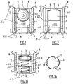
figure 1 est une vue en coupe axiale représentant un mode de réalisation ne faisant pas partie de l'invention dans lequel l'obturateur est constitué par un flotteur sphérique; - la
figure 2 est une vue en coupe axiale représentant un mode de réalisation ne faisant pas partie de l'invention dans lequel l'obturateur est constitué par un flotteur cylindrique à tête tronconique; - la
figure 3a est une vue en coupe axiale représentant un mode de réalisation ne faisant pas partie de l'invention dans lequel l'obturateur est constitué par un flotteur sollicité vers sa position de repos par un ressort; - la
figure 3b une vue du dessus d'un obturateur utilisable dans le mode de réalisation particulier constituant une variante de lafigure 3a ; - la
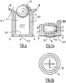
figure 4 est une vue en coupe axiale représentant un mode de réalisation ne faisant pas partie de l'invention dans lequel l'obturateur est constitué par un flotteur maintenu dans sa position de repos par une languette semi-rigide; - la
figure 5a est une vue en coupe axiale représentant un mode de réalisation ne faisant pas partie de l'invention dans lequel la sortie de la chambre est constituée par un orifice d'écoulement cruciforme; - la
figure 5b est une vue de face de la sortie de la chambre cruciforme illustrée à lafigure 5a ; - la
figure 6a est une vue en coupe axiale représentant un mode de réalisation utile à la compréhension mais ne faisant pas partie de l'invention dans lequel l'obturateur est constitué par un diaphragme illustré dans sa position de repos; - la
figure 6b est une vue latérale en élévation du mode de réalisation illustré à lafigure 6a ; - la
figure 6c est une autre vue en coupe axiale du mode de réalisation illustré à lafigure 6a , dans lequel l'obturateur est représenté dans sa position extrême; - la
figure 6d est une vue de dessus du mode de réalisation illustré à lafigure 6b ; - la
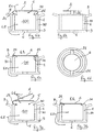
figure 7a est une vue en coupe axiale représentant un mode de réalisation ne faisant pas partie de l'invention dans lequel l'obturateur est constitué par un volet simple illustré en pointillés dans sa position de repos et en trait plein dans une position intermédiaire; - la
figure 7b est une vue en coupe axiale du mode de réalisation illustré à lafigure 7a , dans lequel l'obturateur est représenté dans sa position extrême; - la
figure 8a est une vue en coupe axiale représentant le mode de réalisation de l'invention dans lequel l'obturateur est constitué par un diaphragme illustré dans sa position de repos, et dans lequel la chambre est fermée par le diaphragme associé à un piston et présente un volume variable, cette chambre étant représentée avec son volume maximal; - la
figure 8b est une vue en coupe axiale du mode de réalisation de l'invention illustré à lafigure 8a et observé dans un état transitoire postérieur à celui qu'illustre lafigure 8a , l'obturateur étant représenté dans sa position extrême et la chambre étant toujours représentée avec son volume maximal; - la
figure 8c est une vue en coupe axiale du mode de réalisation de l'invention illustré auxfigures 8a et 8b et observé dans un état transitoire postérieur à celui qu'illustre lafigure 8b , l'obturateur étant toujours représenté dans sa position extrême, et la chambre étant représentée avec son volume minimal; - la
figure 8d est une vue en coupe axiale du mode de réalisation de l'invention illustré auxfigures 8a à 8c et observé dans un état transitoire postérieur à celui qu'illustre lafigure 8c , l'obturateur étant à nouveau représenté dans sa position de repos, alors que la chambre est toujours représentée avec son volume minimal; - la
figure 8e est une vue en coupe axiale du mode de réalisation de l'invention illustré auxfigures 8a à 8d et observé dans un état stable postérieur à celui qu'illustre lafigure 8d et identique à l'état initial illustré à lafigure 8a , l'obturateur étant retourné à sa position de repos, et la chambre ayant repris son volume maximal; - la
figure 8f est une vue de dessus du mode de réalisation de l'invention illustré à lafigure 8e ; - la
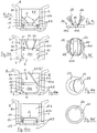
figure 9a est une vue en coupe axiale représentant un mode de réalisation ne faisant pas partie de l'invention dans lequel l'obturateur est constitué par un double volet illustré dans sa position extrême, et dans lequel la chambre est fermée par ce double volet associé à un piston, cette chambre présentant un volume variable et étant représentée avec son volume minimal; - la
figure 9b est une vue en coupe axiale du mode de réalisation illustré à lafigure 9a et observé dans un état initial stable, l'obturateur étant représenté dans sa position de repos, et la chambre étant représentée avec son volume maximal; - la
figure 9c est une vue latérale du piston et de l'obturateur du mode de réalisation illustré auxfigures 9a et 9b , l'obturateur étant représenté en trait plein dans sa position de repos, et, en pointillés, dans une position intermédiaire et dans sa position extrême; - la
figure 9d est une vue de dessus du piston et de l'obturateur du mode de réalisation illustré auxfigures 9a à 9c , le piston et l'obturateur étant représentés dans deux des positions qu'ils occupent sur lafigure 9c ; - la
figure 10a est une vue en coupe axiale représentant un mode de réalisation ne faisant pas partie de l'invention dans lequel l'obturateur est constitué par un volet simple illustré dans sa position de repos, et dans lequel la chambre est fermée par ce volet associé à un piston, cette chambre présentant un volume variable et étant représentée avec son volume maximal; - la
figure 10b est une vue de dessus du piston et de l'obturateur du mode de réalisation illustré à lafigure 10a , le piston et l'obturateur étant représentés dans la position qu'ils occupent sur cettefigure 10a ; - la
figure 10c est une vue en coupe axiale du mode de réalisation illustré auxfigures 10a et 10b , l'obturateur étant représenté dans sa position extrême, et la chambre étant représentée avec son volume minimal; et - la
figure 10d est une vue de dessus du piston et de l'obturateur du mode de réalisation illustré auxfigures 10a à 10c , le piston et l'obturateur étant représentés dans la position qu'ils occupent sur lafigure 10c .
- the
figure 1 is an axial sectional view showing an embodiment not forming part of the invention in which the shutter is constituted by a spherical float; - the
figure 2 is an axial sectional view showing an embodiment not forming part of the invention in which the shutter is constituted by a cylindrical float with a frustoconical head; - the
figure 3a is an axial sectional view showing an embodiment not forming part of the invention in which the shutter is constituted by a float urged towards its rest position by a spring; - the
figure 3b a top view of a shutter that can be used in the particular embodiment constituting a variant of thefigure 3a ; - the
figure 4 is an axial sectional view showing an embodiment not forming part of the invention in which the shutter is constituted by a float held in its rest position by a semi-rigid tongue; - the
figure 5a is an axial sectional view showing an embodiment not forming part of the invention in which the outlet of the chamber is constituted by a cruciform flow orifice; - the
figure 5b is a front view of the exit of the cruciform chamber shown infigure 5a ; - the
figure 6a is an axial sectional view showing an embodiment useful for understanding but not forming part of the invention in which the shutter is constituted by a diaphragm shown in its rest position; - the
figure 6b is a side elevational view of the embodiment illustrated infigure 6a ; - the
figure 6c is another view in axial section of the embodiment illustrated infigure 6a , in which the shutter is shown in its extreme position; - the
figure 6d is a top view of the embodiment illustrated onfigure 6b ; - the
figure 7a is an axial sectional view showing a mode of embodiment not forming part of the invention in which the shutter consists of a single shutter illustrated in dotted lines in its rest position and in solid lines in an intermediate position; - the
figure 7b is an axial sectional view of the embodiment illustrated infigure 7a , in which the shutter is shown in its extreme position; - the
figure 8a is an axial sectional view showing the embodiment of the invention in which the shutter is constituted by a diaphragm shown in its rest position, and in which the chamber is closed by the diaphragm associated with a piston and has a volume variable, this chamber being represented with its maximum volume; - the
figure 8b is an axial sectional view of the embodiment of the invention illustrated infigure 8a and observed in a transient state subsequent to that illustrated byfigure 8a , the shutter being shown in its extreme position and the chamber still being shown with its maximum volume; - the
figure 8c is an axial sectional view of the embodiment of the invention illustrated infigures 8a and 8b and observed in a transient state subsequent to that illustrated byfigure 8b , the shutter still being shown in its extreme position, and the chamber being shown with its minimum volume; - the
figure 8d is an axial sectional view of the embodiment of the invention illustrated infigures 8a to 8c and observed in a transient state subsequent to that illustrated byfigure 8c , the shutter being again shown in its rest position, while the chamber is still shown with its minimum volume; - the
figure 8e is an axial sectional view of the embodiment of the invention illustrated infigures 8a to 8d and observed in a stable state subsequent to that illustrated byfigure 8d and identical to the initial state shown infigure 8a , the shutter being returned to its rest position, and the chamber having returned to its maximum volume; - the
figure 8f is a top view of the embodiment of the invention illustrated infigure 8e ; - the
figure 9a is an axial sectional view showing an embodiment not forming part of the invention in which the shutter is constituted by a double shutter illustrated in its extreme position, and in which the chamber is closed by this double flap associated with a piston, this chamber having a variable volume and being shown with its minimum volume; - the
figure 9b is an axial sectional view of the embodiment illustrated infigure 9a and observed in a stable initial state, the shutter being shown in its rest position, and the chamber being shown with its maximum volume; - the
figure 9c is a side view of the piston and shutter of the embodiment illustrated infigures 9a and 9b , the shutter being shown in solid lines in its rest position, and, in dotted lines, in an intermediate position and in its extreme position; - the
figure 9d is a top view of the piston and the shutter of the embodiment illustrated infigures 9a to 9c , the piston and the shutter being shown in two of the positions they occupy on thefigure 9c ; - the
figure 10a is an axial sectional view showing an embodiment not forming part of the invention in which the shutter consists of a single shutter shown in its rest position, and in which the chamber is closed by this shutter associated with a piston, this chamber having a variable volume and being shown with its maximum volume; - the
figure 10b is a top view of the piston and the shutter of the embodiment illustrated infigure 10a , the piston and the shutter being shown in the position they occupy on thisfigure 10a ; - the
figure 10c is an axial sectional view of the embodiment illustrated infigures 10a and 10b , the shutter being shown in its extreme position, and the chamber being shown with its minimum volume; and - the
figure 10d is a top view of the piston and the shutter of the embodiment illustrated infigures 10a to 10c , the piston and the shutter being shown in the position they occupy on thefigure 10c .
Comme annoncé précédemment, l'invention concerne un dispositif doseur permettant de transférer, depuis un espace amont E1 vers un espace aval E2, un volume prédéterminé de fluide liquide ou pâteux en réponse à une élévation de pression de ce fluide dans l'espace amont E1.As previously announced, the invention relates to a metering device making it possible to transfer, from an upstream space E1 to a downstream space E2, a predetermined volume of liquid or pasty fluid in response to a rise in pressure of this fluid in the upstream space E1. .
Comme le montrent notamment les
Dans sa forme la plus complète, le dispositif de l'invention comprend en outre un récipient 8 (représenté de façon seulement partielle sur les figures) propre à contenir le fluide à distribuer, et doté d'un goulot 80 constituant le seul exutoire du fluide.In its most complete form, the device of the invention further comprises a container 8 (shown only partially in the figures) suitable for containing the fluid to be dispensed, and provided with a
Le volume interne délimité par ce récipient, qui constitue au moins partiellement l'espace amont E1, présente une capacité variable.The internal volume delimited by this container, which at least partially constitutes the upstream space E1, has a variable capacity.
A cette fin, le récipient peut par exemple comporter une paroi souple et élastiquement déformable, de sorte qu'une pression exercée sur cette paroi par un utilisateur provoque une réduction transitoire du volume de l'espace amont E1 et une élévation concomitante de la pression du fluide contenu dans le récipient.To this end, the container may for example comprise a flexible and elastically deformable wall, so that a pressure exerted on this wall by a user causes a transient reduction in the volume of the upstream space E1 and a concomitant increase in the pressure of the fluid contained in the container.
En variante, le récipient peut n'être formé que de parois rigides, mais comporter un piston actionnable par l'utilisateur pour provoquer une réduction transitoire du volume de l'espace amont E1 et une élévation concomitante de la pression du fluide contenu dans ce récipient.As a variant, the container may be formed only of rigid walls, but include a piston actuable by the user to cause a transient reduction in the volume of the upstream space E1 and a concomitant increase in the pressure of the fluid contained in this container. .
Le corps creux 1 est disposé de façon étanche dans le goulot 80 de ce récipient 8. En particulier, le corps creux 1 peut être inséré à force dans le goulot 80 jusqu'à ce qu'une butée 9 du corps creux vienne en appui sur ce goulot.The
Le corps creux 1, de forme par exemple essentiellement cylindrique, délimite au moins partiellement une chambre 100 dotée d'une entrée 5 et d'une sortie 6.The
L'obturateur 2 est mobile par rapport au corps creux 1 entre une position de repos par exemple illustrée aux
L'obturateur 2 est sollicité vers sa position de repos par une force de rappel, et sollicité vers sa position extrême, lors de l'application d'une pression différentielle entre l'entrée 5 de la chambre et la sortie 6 de cette chambre, par le fluide circulant de l'espace amont E1 vers l'espace aval E2, l'espace amont E1 s'étendant au moins à l'extérieur de la chambre 100 du côté de son entrée 5, et l'espace aval E2 s'étendant au moins à l'extérieur du dispositif et de la chambre 100 du côté de sa sortie 6.The
Dans sa position classique de repos, le récipient ou flacon 8 est posé verticalement de manière que son goulot 80 soit tourné vers le bas, le fluide à distribuer ayant donc spontanément tendance à s'écouler par gravité de l'espace amont E1 vers l'espace aval E2, et de l'entrée 5 de la chambre 100 vers la sortie 6 de cette chambre.In its conventional rest position, the container or
Selon l'invention, l'obturateur 2 isole l'un de l'autre l'espace amont E1 et l'espace aval E2 dans sa position extrême, et seulement dans cette position.According to the invention, the
Par ailleurs, la sortie 6 de la chambre 100 communique avec l'espace amont E1 pour toute position de l'obturateur 2 autre que sa position extrême.Furthermore, the
Comme le montrent notamment les
En outre, comme le montrent les
Les
Dans ce cas, l'obturateur 2, lorsqu'il baigne dans le fluide à distribuer, se comporte comme un flotteur, de sorte que la force de rappel qui sollicite cet obturateur vers sa position de repos est au moins partiellement constituée par la force d'Archimède qui s'exerce sur lui.In this case, the
Dans la suite de la présente description des modes de réalisation des
En outre, le récipient ou flacon 8 sera considéré comme étant orienté de façon que son goulot 80 soit tourné vers le bas.In addition, the container or
Dans le premier mode de réalisation détaillé illustré à la
Ce corps creux 1 est inséré à force dans le goulot 80 du récipient 8 contenant le fluide à doser jusqu'à ce qu'une butée 9 de ce corps 1 vienne en contact contre ce goulot.This
Par ailleurs, un bouchon 3 est inséré à force dans la partie basse du corps creux 1 jusqu'à ce qu'une butée 7 de ce bouchon 3 vienne en contact contre ce corps 1.Furthermore, a
L'entrée 5 de la chambre 100 prend la forme d'un orifice ménagé dans le corps creux 1, et la sortie 6 de la chambre 100 prend la forme d'un orifice ménagé dans le bouchon 3.The
La taille et / ou la forme de la sortie de la chambre 6 du fluide peuvent ainsi être modifiées à volonté en remplaçant le bouchon 3 inséré dans le goulot 80 par un autre bouchon 3 possédant un orifice d'écoulement 6 de taille et / ou de forme différente.The size and / or the shape of the outlet of the
Deux rainures 4, par exemple conformées en U à et disposées à 90° les unes des autres, sont pratiquées dans la partie haute du corps creux 1 afin d'éviter au flotteur 2 d'obturer de manière étanche l'orifice 5 d'entrée de la chambre 100, qui est situé dans la partie supérieure du corps creux 1.Two
Le bord de la partie évidée du bouchon 3 forme un siège d'étanchéité 30 permettant au flotteur 2, lorsqu'il vient en appui sur ce siège 30 dans sa position extrême sous l'effet d'une élévation de la pression du fluide dans l'espace amont E1, d'isoler cet espace amont E1 de l'espace aval E2, et d'interrompre l'écoulement du fluide à travers l'orifice calibré 6 de sortie de la chambre 100.The edge of the recessed portion of the
Le jeu annulaire entre le corps creux 1 et le flotteur 2 est dimensionné de manière à permettre un écoulement par gravité du fluide sous le flotteur 2. Ainsi, dès que la pression du fluide dans l'espace amont E1 est relâchée, autorisant le fluide à s'écouler à nouveau sous le flotteur 2, ce flotteur est soumis, en raison de sa masse volumique inférieure à celle du fluide, à une force d'Archimède qui rappelle le flotteur 2 au contact de la partie haute du corps creux 1, c'est-à-dire dans sa position de repos illustrée à la
Pour faire apparaître, au sein du fluide à distribuer, la pression différentielle nécessaire du déplacement du flotteur 2, il convient de prévoir que la section de passage de l'orifice 6 de sortie de la chambre 100 soit supérieure à la section de passage offerte par le jeu annulaire entre le flotteur 2 et le corps creux 1.To reveal, within the fluid to be distributed, the differential pressure necessary for the displacement of the
Lorsqu'une pression est exercée sur le flacon souple 8 pour expulser le fluide contenu dans l'espace amont E1, le flotteur 2 est sollicité par le fluide en mouvement vers le bas du corps creux 1, pendant que la majorité du fluide contenu dans la chambre 100 entre le flotteur 2 et le bouchon 3 traverse l'orifice 6 de sortie de la chambre. Puis, le flotteur 2 vient en butée contre le bouchon sur le siège d'étanchéité 30 qu'il obture, interdisant l'expulsion supplémentaire de fluide. Le relâchement ultérieur de la pression sur le flacon 8 et donc dans l'espace amont E1 crée une dépression qui, par un léger soulèvement du flotteur, fait rentrer de l'air dans la chambre 100.When pressure is exerted on the
Le flacon souple 8 peut ainsi revenir à sa position de repos, et le fluide, qui s'écoule par gravité dans le corps creux 1, remonte progressivement le flotteur 2 en position haute vers sa position de repos, par l'action de la poussée d'Archimède.The
La
Dans le troisième mode de réalisation illustré à la
De préférence, la force élastique exercée par le ressort 10 sur le flotteur 2 est dimensionnée pour compenser seulement le poids du flotteur 2, le ressort 10 servant uniquement à favoriser la remontée du flotteur 2 lorsque le fluide coule en partie basse du corps creux 1. Cet agencement, qui permet aisément de vaincre les frottements visqueux, est plus particulièrement adapté au cas où le fluide à distribuer présente une viscosité élevée.Preferably, the elastic force exerted by the
La
La
Lorsque le flacon 8 est en position de repos, goulot 80 vers le bas, le fluide contenu dans ce flacon 8 coule par gravité jusqu'à remplir la chambre 100 délimitée par le corps creux 1, de sorte que le flotteur est ramené dans sa position de repos, par la poussée d'Archimède, en butée contre la languette 11.When the
Une pression exercée sur le flacon 8 entraîne le fluide contenu dans ce dernier vers le goulot 80. Le fluide en mouvement exerce une pression sur le flotteur 2, qui se déplace vers le bas en chassant, par l'orifice de sortie 6, le fluide contenu dans la chambre 100. Une fois que le flotteur 2 est en appui sur le siège 30 entourant l'orifice de sortie 6, cet orifice est obturé et l'écoulement de fluide hors de la chambre 100 et vers l'espace aval E2 est interrompu. Le relâchement de la pression sur la surface du flacon 8 produit une dépression qui a pour effet de faire rentrer de l'air dans le corps creux 1, ramenant le flacon à son état de repos. Grâce au jeu annulaire entre le flotteur 2 et la paroi intérieure du corps creux cylindrique 1, le fluide s'écoule à nouveau dans la chambre 100 par gravité et passe sous le flotteur 2, de sorte que la force d'Archimède exercée sur ce flotteur 2 le ramène progressivement dans sa position de repos, en butée sur la languette semi-rigide 11.A pressure exerted on the
Le matériau semi-rigide constitutif de la languette 11 est choisi suffisamment souple pour pouvoir subir sans casser la déformation nécessaire à l'insertion en force du flotteur 2 dans le corps creux 1, mais suffisamment rigide pour ne pas subir, sous l'effet de la force d'Archimède exercée sur le flotteur 2, de déformation qui permettrait à ce flotteur de s'échapper du corps creux à partir de sa position de repos dans laquelle il s'appuie sur cette languette. Le mode de réalisation de la
Les
Selon cette variante, la sortie de la chambre 6 est percée dans une paroi élastiquement déformable et présente une section de passage croissant de façon réversible sous l'effet de la pression du fluide.According to this variant, the outlet of the
En l'occurrence, le fond 12 du corps creux, dans lequel est formé l'orifice d'écoulement 6 constituant la sortie de la chambre 100, est réalisé dans un matériau élastiquement déformable présentant une découpe cruciforme, et l'obturateur 2 présente une forme cylindrique.In this case, the bottom 12 of the hollow body, in which the
Lorsque la pression exercée sur le flacon souple 8 fait descendre le flotteur 2 en butée vers sa position basse extrême sur le siège 30, la poussée exercée par le fluide mis en mouvement en même temps que le flotteur 2 exerce sur le fond 12 une pression qui déforme chacune des parties de la découpe cruciforme, de sorte que l'aire de la sortie 6 de la chambre 100 augmente de façon réversible selon une fonction croissante de cette pression.When the pressure exerted on the
Une fois arrivé en butée en partie basse dans sa position extrême, le flotteur 2 obture la sortie 6 et empêche tout écoulement de fluide. Sans pression extérieure, la seule force engendrée par la hauteur de fluide dans le flacon ne peut vaincre l'élasticité des lamelles souples formées aux coins de la sortie cruciforme 6 de la chambre 100, le fluide étant donc retenu dans le dispositif doseur.Once it has come to a stop at the bottom in its extreme position, the
La section de passage du fond 12 à l'état repos ne permet pas l'écoulement de fluide venant du flacon mais permet, après relâchement de la pression sur le flacon, de faire rentrer l'air dans celui-ci pour permettre au flacon de retrouver sa position initiale.The passage section of the bottom 12 in the rest state does not allow the flow of fluid from the bottle but allows, after release of the pressure on the bottle, to bring the air into the latter to allow the bottle to regain its initial position.
Les
Dans le mode de réalisation des
Dans ce mode de réalisation, le corps creux 1, l'obturateur 2 et chacune des languettes élastiques 21 sont de préférence réalisés d'une seule pièce en un matériau élastique.In this embodiment, the
Le siège d'étanchéité 30, sur lequel s'appuie l'obturateur 2 dans sa position extrême, est formé sur la partie haute du corps creux 1 et entoure un passage de fluide disposé entre l'espace amont E1 et l'espace aval E2 et formant l'entrée 5 de la chambre 100.The sealing
Au repos, l'obturateur 2 occupe la position illustrée aux
Lorsque le fluide dans l'espace amont E1 subit une pression qui le pousse vers la sortie 6, l'énergie cinétique communiquée au fluide exerce sur l'obturateur 2 une force de traînée qui le sollicite vers sa position extrême illustrée à la ![]()
- où p représente la densité du fluide;
- où S représente le maître-couple de l'obturateur 2;
- où V est la vitesse du fluide; et
- où Cx représente le coefficient de traînée, lié à la forme de l'obturateur.
- where p represents the density of the fluid;
- where S represents the master torque of
shutter 2; - where V is the speed of the fluid; and
- where Cx represents the drag coefficient, related to the shape of the shutter.
Comme dans les modes de réalisation précédents, le fluide qui traverse le corps creux 1 sous l'effet d'une augmentation de la pression à l'entrée 5 de la chambre 100 entraîne l'obturateur 2 de sa position de repos (
Le mode de réalisation des
Le mode de réalisation des
En revanche, le mode de réalisation des
Le piston 14 est monté coulissant dans le corps creux 1 et l'obturateur 2 est porté par le piston 14 au moyen de deux languettes élastiques 21 de la même manière qu'il était porté par le corps creux 1 dans le mode de réalisation des
Le piston 14 présente une forme essentiellement annulaire (
Le ressort 15 est quant à lui précontraint en compression et disposé entre le bouchon 3 et le piston 14, de sorte qu'il tend à donner à la chambre 100 un volume maximal.The
Une butée 140 est formée sur la périphérie interne du corps creux 1 pour limiter la course du piston 14 vers le haut en définissant une position haute maximale de ce piston dans le corps creux 1.A
Le fonctionnement du dispositif doseur selon ce mode de réalisation est illustré de façon séquentielle et chronologique sur les
La
L'élévation de la pression dans le flacon 8 provoque le déplacement de l'obturateur 2 vers sa position extrême illustrée à la
Dans la mesure où la pression du fluide s'exerce alors sur toute la surface du piston 14 fermé par l'obturateur 2, ce piston se déplace vers le bas en réduisant le volume de la chambre 100, en provoquant l'expulsion, à travers la sortie 6, du fluide contenu dans cette chambre, et en comprimant corrélativement le ressort 15, ce mouvement étant interrompu lorsque le piston 14 vient en appui sur le bouchon 3 (
Après relâchement de la pression du fluide dans le flacon 8, la force élastique de rappel exercée par les languettes 21 ramène l'obturateur 2 dans sa position de repos (
Grâce au ressort 15, qui sollicite le piston 14 vers le haut, et au fluide qui s'écoule dans la chambre 100, cette dernière reprend son volume maximal initial (
Grâce à son agencement, le mode de réalisation des
Les
En outre, dans ces deux cas, la chambre est partiellement délimitée par un bouchon 3 inséré dans le corps creux 1, et ce dernier comporte une butée périphérique interne 140 permettant de limiter la course du piston 14 vers le haut.In addition, in these two cases, the chamber is partially delimited by a
Dans le mode de réalisation des
De préférence, le piston 14, chacun des volets 22 formant l'obturateur 2, et chacune des languettes élastiques 21 formant charnières sont réalisés d'une seule pièce en un matériau élastique.Preferably, the
Le mode de réalisation des
Dans le mode de réalisation des
En fait, le mode de réalisation des
De préférence, le piston 14, le volet 23 formant l'obturateur 2, et la languette élastique 21 formant charnière sont réalisés d'une seule pièce en un matériau élastique.Preferably, the
Comme dans le mode de réalisation des
Claims (3)
- A metering device for transferring, from an upstream space (E1) to a downstream space (E2), a predetermined volume of liquid or pasty fluid in response to a pressure rise in this fluid in the upstream space (E1), this device comprising at least one hollow body (1), a stopper (2), and a sealing seat (30) defined on an annular element (14) and surrounding a fluid passageway disposed between the upstream space (E1) and downstream space (E2), the hollow body at least partially delimiting a chamber (100) provided with an inlet (5) and outlet (6), the stopper (2) being movable with respect to the annular element (14) between a rest position, to which this stopper (2) is biased by a return force at least partially consisting of an elastic return force, and an end position, which is remote from the rest position, to which this stopper (2) is selectively biased by the fluid circulating from the upstream space (E1) to downstream space (E2), the stopper bearing against said sealing seat in said end position, the upstream space (E1) extending at least outside the chamber (100) on the side of its inlet (5), the downstream space (E2) extending at least outside the device and the chamber (100) on the side of its outlet (6), the stopper (2) isolating the upstream space (E1) and downstream space (E2) from each other in its end position and only in this position, and the outlet (6) of the chamber (100) communicating with the upstream space (E1) for any position of the stopper (2) other than its end position, wherein the stopper (2) comprises a diaphragm translationally movable with respect to the annular element (14) and at least one elastic tab (21) attaching the stopper (2) to the annular element (14), wherein this annular element (14), the stopper (2), and each elastic tab (21) are made as a single piece of an elastic material, and wherein the return force is exerted by each elastic tab (21), characterised in that it further comprises a plug (3) inserted into the hollow body (1), this plug being pierced with a flowing hole forming the outlet (6) of the chamber (100), in that it further comprises a piston (14) and a spring (15), in that the piston (14) is slidably mounted in the hollow body (1) and carries said stopper (2), and in that the spring (15) is prestressed in compression and disposed between the plug (3) and piston (14), and in that said annular element consists of said piston (14).
- The metering device according to claim 1, characterised in that it comprises two elastic tabs (21) diametrically opposite to each other.
- The metering device according to any of the previous claims, characterised in that it further comprises a container (8) provided with a spout (80), this container being capable of containing the fluid and delimiting a variable-volume upstream space (E1), the pressure rise in the fluid being achieved by reducing the volume of the upstream space (E1), and in that the hollow body (1) is sealingly disposed in the spout (80) of this container (8).
Priority Applications (1)
| Application Number | Priority Date | Filing Date | Title |
|---|---|---|---|
| EP14157367.5A EP2746733B1 (en) | 2008-11-05 | 2009-11-04 | Metering device with differential pressure |
Applications Claiming Priority (2)
| Application Number | Priority Date | Filing Date | Title |
|---|---|---|---|
| FR0806164A FR2938057B1 (en) | 2008-11-05 | 2008-11-05 | PRESSURE DELTA DOSER |
| PCT/FR2009/001277 WO2010052390A1 (en) | 2008-11-05 | 2009-11-04 | Differential pressure metering device |
Related Child Applications (2)
| Application Number | Title | Priority Date | Filing Date |
|---|---|---|---|
| EP14157367.5A Division-Into EP2746733B1 (en) | 2008-11-05 | 2009-11-04 | Metering device with differential pressure |
| EP14157367.5A Division EP2746733B1 (en) | 2008-11-05 | 2009-11-04 | Metering device with differential pressure |
Publications (2)
| Publication Number | Publication Date |
|---|---|
| EP2342542A1 EP2342542A1 (en) | 2011-07-13 |
| EP2342542B1 true EP2342542B1 (en) | 2020-09-16 |
Family
ID=40852651
Family Applications (2)
| Application Number | Title | Priority Date | Filing Date |
|---|---|---|---|
| EP14157367.5A Active EP2746733B1 (en) | 2008-11-05 | 2009-11-04 | Metering device with differential pressure |
| EP09784338.7A Active EP2342542B1 (en) | 2008-11-05 | 2009-11-04 | Differential pressure dosing device |
Family Applications Before (1)
| Application Number | Title | Priority Date | Filing Date |
|---|---|---|---|
| EP14157367.5A Active EP2746733B1 (en) | 2008-11-05 | 2009-11-04 | Metering device with differential pressure |
Country Status (8)
| Country | Link |
|---|---|
| US (3) | US8997788B2 (en) |
| EP (2) | EP2746733B1 (en) |
| JP (2) | JP2012507451A (en) |
| CA (2) | CA2909853C (en) |
| DE (1) | DE202009019069U1 (en) |
| ES (1) | ES2743053T3 (en) |
| FR (1) | FR2938057B1 (en) |
| WO (1) | WO2010052390A1 (en) |
Families Citing this family (22)
| Publication number | Priority date | Publication date | Assignee | Title |
|---|---|---|---|---|
| FR2938057B1 (en) | 2008-11-05 | 2013-05-17 | Patrick Wozna | PRESSURE DELTA DOSER |
| EP2390009A1 (en) * | 2010-05-31 | 2011-11-30 | Scandinavian Amenities A/S | Metering arrangement for dispensing metered quantities of liquid from a deformable container |
| WO2012171708A1 (en) * | 2011-06-17 | 2012-12-20 | Unilever Plc | Dispenser cap |
| EP2850660A1 (en) | 2012-05-17 | 2015-03-25 | General Electric Company | Semiconductor device with junction termination extension |
| EP3584308A3 (en) | 2013-02-04 | 2020-03-04 | Seres Therapeutics, Inc. | Compositions and methods |
| GB201403942D0 (en) * | 2014-03-06 | 2014-04-23 | Obrist Closures Switzerland | A dosing device |
| DE102014206568A1 (en) * | 2014-04-04 | 2015-10-08 | Aptar Radolfzell Gmbh | Dosing device for a liquid dispenser and liquid dispenser with such |
| US10071836B2 (en) * | 2014-04-16 | 2018-09-11 | Reckitt Benckiser (Brands) Limited | Dosing dispensing closure |
| EP3088851A1 (en) | 2015-04-28 | 2016-11-02 | Aptar Freyung GmbH | Liquid dosing device |
| EP2993447A1 (en) | 2014-09-04 | 2016-03-09 | Aptar Freyung GmbH | Liquid dosing device |
| CN106687219A (en) * | 2014-09-04 | 2017-05-17 | 阿帕达弗赖翁有限公司 | Liquid dosing device |
| JP6478564B2 (en) * | 2014-11-06 | 2019-03-06 | 東京ライト工業株式会社 | Pouring spout |
| EP3023752A1 (en) * | 2014-11-18 | 2016-05-25 | Aptar Radolfzell GmbH | Liquid dispenser and applicator head for the same |
| EP3035009A1 (en) | 2014-12-18 | 2016-06-22 | Aptar Radolfzell GmbH | Liquid dispenser and indicator device |
| NL2014031B1 (en) * | 2014-12-22 | 2016-10-12 | Plasticum Netherlands B V | Dosing cap. |
| WO2017001954A1 (en) * | 2015-06-29 | 2017-01-05 | Meadwestvaco Calmar Netherlands, B.V. | Measured dose dispensers and methods of using same |
| WO2017182972A1 (en) | 2016-04-19 | 2017-10-26 | Flexidose | Dosing dispenser |
| CN110891874B (en) * | 2017-04-27 | 2022-03-18 | 伊利诺斯工具制品有限公司 | Flexible ball valve for metering and dispensing liquids |
| WO2022236219A1 (en) * | 2021-04-20 | 2022-11-10 | Flexpenser Ab | Dosing applicator for medical and non-medical containers |
| FR3130770B1 (en) | 2021-12-17 | 2023-12-08 | Aptar France Sas | Fluid dosing device |
| US11904330B2 (en) * | 2022-02-28 | 2024-02-20 | L'oreal | Cosmetic dispenser with accordion bladder valve system |
| US11860017B2 (en) | 2022-02-28 | 2024-01-02 | L'oreal | Cosmetic dispenser with bladder valve system |
Citations (1)
| Publication number | Priority date | Publication date | Assignee | Title |
|---|---|---|---|---|
| JPS5041946U (en) * | 1973-08-08 | 1975-04-28 |
Family Cites Families (39)
| Publication number | Priority date | Publication date | Assignee | Title |
|---|---|---|---|---|
| US2970722A (en) * | 1958-07-07 | 1961-02-07 | Gadget Of The Month Club Inc | Pressure seal for pressurized liquid container |
| US3567079A (en) | 1968-08-08 | 1971-03-02 | Cleone H Weigand | Dispenser container with metering neck |
| SE381336B (en) | 1972-12-15 | 1975-12-01 | B Nilson | FLUIDING DOSAGE DEVICE |
| JPS5727122B2 (en) | 1973-08-20 | 1982-06-09 | ||
| JPS5274164U (en) * | 1975-11-29 | 1977-06-02 | ||
| JPS5274164A (en) | 1975-12-16 | 1977-06-21 | Nippon Steel Corp | Screening by vibrating strainers |
| US4049162A (en) | 1976-03-05 | 1977-09-20 | Yule Lance S | Metering valve |
| SE413623B (en) | 1978-03-22 | 1980-06-16 | Kenova Ab | DEVICE FOR PORTION EXPENSION OF LIQUID FROM A CONTAINER |
| US4215724A (en) * | 1978-03-17 | 1980-08-05 | The Logsdon Foundation | Backflow preventer for sewer system |
| DE3308013A1 (en) | 1983-03-07 | 1984-09-13 | Henkel KGaA, 4000 Düsseldorf | DOSING DEVICE |
| US5078305A (en) | 1989-11-24 | 1992-01-07 | Delta Dispensing, Inc. | Simultaneous fill-dispense invert dispenser container |
| US5046526A (en) | 1990-11-28 | 1991-09-10 | Morley Longmore | One-way check valve |
| SE501000C2 (en) * | 1992-02-03 | 1994-10-17 | Jana System Ab | Liquid substance dispensing device |
| DE4305390C1 (en) | 1993-02-22 | 1994-01-27 | Design Udo Suffa Gmbh S | Fluid container with controlled feed chamber - incorporates rise pipe, overflow connection and freely movable rod connected to float and closure piston |
| DE19700607A1 (en) | 1996-11-19 | 1998-05-20 | Elvira Ahrens | Adjustable dispensing head for pressurised bottle containing weed killer, flower fertiliser, etc. |
| NL1009549C2 (en) | 1997-08-01 | 1999-02-02 | Sara Lee De Nv | Assembly provided with a flexible holder with a dosing device and a dosing device of such an assembly. |
| US6068165A (en) | 1998-09-02 | 2000-05-30 | Minihane; Denis A. | Premeasured dispensing bottle cap |
| FR2784968B1 (en) | 1998-10-23 | 2000-12-01 | Oreal | METERING CAP AND CONTAINER PROVIDED WITH A METERING CAP according to the invention |
| NL1010749C2 (en) | 1998-12-07 | 2000-06-08 | V O F Pharmasept | Holder for dosed and substantially germ-free dispensing of a liquid. |
| JP3068076U (en) | 1999-10-08 | 2000-04-21 | 健一 若林 | Dripping container |
| US6997358B2 (en) | 2001-09-12 | 2006-02-14 | Anthony Charles Lammond Wass | Liquid dosing device |
| US6662973B1 (en) * | 2002-07-02 | 2003-12-16 | Stephen P. Velliquette | Fluid flow control valve/seal for fluid dispensers |
| US7494028B2 (en) | 2003-10-15 | 2009-02-24 | Zavida Coffee Company Inc. | Fluid dispensing system suitable for dispensing liquid flavorings |
| JP2005138900A (en) | 2003-10-16 | 2005-06-02 | Daipura Kk | Liquid packaging container |
| JP2006334537A (en) * | 2005-06-03 | 2006-12-14 | Nitto Denko Corp | Aeration member, aeration member kit, ventilation basket using these, and ventilation tank |
| JP2007069931A (en) | 2005-09-06 | 2007-03-22 | Nisshin Kagaku Kk | Storing container for content |
| US7726520B2 (en) | 2005-12-22 | 2010-06-01 | Innopak Inc. | Metered dispenser with feed-containing piston drive mechanism |
| AU2008261763B2 (en) | 2007-06-08 | 2013-01-17 | Diversey, Inc. | Fluid dispensing apparatus and method |
| US8136701B2 (en) | 2008-09-23 | 2012-03-20 | Prince Castle, LLC | Fixed-volume liquid dispenser |
| FR2938057B1 (en) | 2008-11-05 | 2013-05-17 | Patrick Wozna | PRESSURE DELTA DOSER |
| US8464904B2 (en) | 2009-04-17 | 2013-06-18 | James M. Woodruff | Methods and containers for reducing spillage and residual liquid when pouring liquid out of a container |
| US8434647B2 (en) | 2009-08-08 | 2013-05-07 | Riad Aamar | Device for measuring and dispensing a prescribed amount of liquid |
| US8356731B2 (en) * | 2009-09-09 | 2013-01-22 | Mtn Products Inc | Energy saving baffle for water cooler |
| WO2011035096A2 (en) | 2009-09-18 | 2011-03-24 | The Procter & Gamble Company | Unit dose dispensing apparatus |
| EP2547455B1 (en) | 2010-03-17 | 2015-10-21 | Ipn Ip B.V. | Container with a portion dispensing device |
| EP2390009A1 (en) | 2010-05-31 | 2011-11-30 | Scandinavian Amenities A/S | Metering arrangement for dispensing metered quantities of liquid from a deformable container |
| CN103025438A (en) | 2010-08-06 | 2013-04-03 | 荷兰联合利华有限公司 | Dosing cap for container |
| US8851333B2 (en) | 2010-11-09 | 2014-10-07 | Conopco, Inc. | Dosing cap for container |
| WO2012171708A1 (en) | 2011-06-17 | 2012-12-20 | Unilever Plc | Dispenser cap |
-
2008
- 2008-11-05 FR FR0806164A patent/FR2938057B1/en active Active
-
2009
- 2009-11-04 US US13/127,972 patent/US8997788B2/en active Active
- 2009-11-04 EP EP14157367.5A patent/EP2746733B1/en active Active
- 2009-11-04 DE DE202009019069.2U patent/DE202009019069U1/en not_active Expired - Lifetime
- 2009-11-04 JP JP2011533786A patent/JP2012507451A/en active Pending
- 2009-11-04 CA CA2909853A patent/CA2909853C/en active Active
- 2009-11-04 ES ES14157367T patent/ES2743053T3/en active Active
- 2009-11-04 CA CA2742898A patent/CA2742898C/en active Active
- 2009-11-04 WO PCT/FR2009/001277 patent/WO2010052390A1/en active Application Filing
- 2009-11-04 EP EP09784338.7A patent/EP2342542B1/en active Active
-
2013
- 2013-12-06 JP JP2013253642A patent/JP2014111476A/en active Pending
-
2014
- 2014-02-25 US US14/189,605 patent/US9446886B2/en active Active
-
2016
- 2016-01-19 US US15/000,804 patent/US20160138954A1/en not_active Abandoned
Patent Citations (1)
| Publication number | Priority date | Publication date | Assignee | Title |
|---|---|---|---|---|
| JPS5041946U (en) * | 1973-08-08 | 1975-04-28 |
Also Published As
| Publication number | Publication date |
|---|---|
| CA2909853A1 (en) | 2010-05-14 |
| FR2938057B1 (en) | 2013-05-17 |
| DE202009019069U1 (en) | 2016-03-10 |
| WO2010052390A1 (en) | 2010-05-14 |
| JP2012507451A (en) | 2012-03-29 |
| ES2743053T3 (en) | 2020-02-18 |
| JP2014111476A (en) | 2014-06-19 |
| CA2742898C (en) | 2016-01-19 |
| US20110277857A1 (en) | 2011-11-17 |
| US20140183230A1 (en) | 2014-07-03 |
| FR2938057A1 (en) | 2010-05-07 |
| US8997788B2 (en) | 2015-04-07 |
| EP2342542A1 (en) | 2011-07-13 |
| EP2746733B1 (en) | 2019-05-29 |
| US20160138954A1 (en) | 2016-05-19 |
| CA2909853C (en) | 2016-12-06 |
| EP2746733A1 (en) | 2014-06-25 |
| US9446886B2 (en) | 2016-09-20 |
| CA2742898A1 (en) | 2010-05-14 |
Similar Documents
| Publication | Publication Date | Title |
|---|---|---|
| EP2342542B1 (en) | Differential pressure dosing device | |
| EP0954485B1 (en) | Device for dispensing a fluid with sealing system | |
| EP0307310B1 (en) | Spray device of the precompression hand pump type for use with a propelling gas | |
| EP1185376B1 (en) | Fluid product dispenser | |
| EP1572375B1 (en) | Manually-actuated metering pump | |
| WO1995025945A1 (en) | Metering device for dispensing constant unit doses | |
| EP3417947B1 (en) | Metering device for equipping a container and container comprising such a device | |
| EP2906484B1 (en) | Metering valve for dispensing an aerosol | |
| EP2229239A1 (en) | Pump for a liquid or viscous product | |
| EP0821775B1 (en) | Inlet valve assembly | |
| EP1914006A2 (en) | Pump comprising air venting means | |
| FR2817244A1 (en) | IMPROVED DEVICE FOR PACKAGING AND DOSED DISPENSING OF A LIQUID PRODUCT | |
| FR2746676A1 (en) | DEVICE FOR DISPENSING A SINGLE DOSE OF FLUID PRODUCT | |
| EP0312474A1 (en) | Automatic dispenser for viscous products | |
| FR2528122A1 (en) | Atomiser operable in all positions - has compression chamber with gravity operated valve | |
| EP0377536A1 (en) | Check valve for introducing a liquid to be sprayed to a pump chamber, and its use | |
| EP1328351B1 (en) | Fluid product dispensing pump | |
| EP0270409B1 (en) | Container for dispensing doses of a treatment liquid | |
| FR2767311A1 (en) | Sealing system for outlet of fluid product | |
| EP3271580A1 (en) | Manual pump | |
| EP3352913B1 (en) | Airless dispensing system with a pump | |
| FR2594419A1 (en) | Method of dispensing a viscous substance in successive doses and package implementing it | |
| FR2786467A1 (en) | Dispenser for liquid fluid or paste products comprises support and push button arranged on container with elastically deformable intermediate piece arranged in between. | |
| EP2874757B1 (en) | Fluid product dispenser | |
| EP3634883B1 (en) | Metering valve and fluid product dispensing device comprising such a valve |
Legal Events
| Date | Code | Title | Description |
|---|---|---|---|
| PUAI | Public reference made under article 153(3) epc to a published international application that has entered the european phase |
Free format text: ORIGINAL CODE: 0009012 |
|
| 17P | Request for examination filed |
Effective date: 20110420 |
|
| AK | Designated contracting states |
Kind code of ref document: A1 Designated state(s): AT BE BG CH CY CZ DE DK EE ES FI FR GB GR HR HU IE IS IT LI LT LU LV MC MK MT NL NO PL PT RO SE SI SK SM TR |
|
| AX | Request for extension of the european patent |
Extension state: AL BA RS |
|
| DAX | Request for extension of the european patent (deleted) | ||
| RAP1 | Party data changed (applicant data changed or rights of an application transferred) |
Owner name: FLEXIDOSE |
|
| RIN1 | Information on inventor provided before grant (corrected) |
Inventor name: WOZNA, PATRICK |
|
| 17Q | First examination report despatched |
Effective date: 20140917 |
|
| 17Q | First examination report despatched |
Effective date: 20141105 |
|
| STAA | Information on the status of an ep patent application or granted ep patent |
Free format text: STATUS: EXAMINATION IS IN PROGRESS |
|
| REG | Reference to a national code |
Ref country code: DE Ref legal event code: R079 Ref document number: 602009062775 Country of ref document: DE Free format text: PREVIOUS MAIN CLASS: G01F0011280000 Ipc: G01F0011040000 |
|
| RIC1 | Information provided on ipc code assigned before grant |
Ipc: B05B 11/02 20060101ALN20200302BHEP Ipc: B05B 11/04 20060101ALI20200302BHEP Ipc: G01F 11/04 20060101AFI20200302BHEP Ipc: G01F 11/28 20060101ALI20200302BHEP |
|
| GRAP | Despatch of communication of intention to grant a patent |
Free format text: ORIGINAL CODE: EPIDOSNIGR1 |
|
| STAA | Information on the status of an ep patent application or granted ep patent |
Free format text: STATUS: GRANT OF PATENT IS INTENDED |
|
| INTG | Intention to grant announced |
Effective date: 20200416 |
|
| GRAS | Grant fee paid |
Free format text: ORIGINAL CODE: EPIDOSNIGR3 |
|
| GRAA | (expected) grant |
Free format text: ORIGINAL CODE: 0009210 |
|
| STAA | Information on the status of an ep patent application or granted ep patent |
Free format text: STATUS: THE PATENT HAS BEEN GRANTED |
|
| AK | Designated contracting states |
Kind code of ref document: B1 Designated state(s): AT BE BG CH CY CZ DE DK EE ES FI FR GB GR HR HU IE IS IT LI LT LU LV MC MK MT NL NO PL PT RO SE SI SK SM TR |
|
| REG | Reference to a national code |
Ref country code: GB Ref legal event code: FG4D Free format text: NOT ENGLISH |
|
| REG | Reference to a national code |
Ref country code: CH Ref legal event code: EP |
|
| REG | Reference to a national code |
Ref country code: DE Ref legal event code: R096 Ref document number: 602009062775 Country of ref document: DE |
|
| REG | Reference to a national code |
Ref country code: IE Ref legal event code: FG4D Free format text: LANGUAGE OF EP DOCUMENT: FRENCH |
|
| REG | Reference to a national code |
Ref country code: AT Ref legal event code: REF Ref document number: 1314564 Country of ref document: AT Kind code of ref document: T Effective date: 20201015 |
|
| PG25 | Lapsed in a contracting state [announced via postgrant information from national office to epo] |
Ref country code: GR Free format text: LAPSE BECAUSE OF FAILURE TO SUBMIT A TRANSLATION OF THE DESCRIPTION OR TO PAY THE FEE WITHIN THE PRESCRIBED TIME-LIMIT Effective date: 20201217 Ref country code: NO Free format text: LAPSE BECAUSE OF FAILURE TO SUBMIT A TRANSLATION OF THE DESCRIPTION OR TO PAY THE FEE WITHIN THE PRESCRIBED TIME-LIMIT Effective date: 20201216 Ref country code: FI Free format text: LAPSE BECAUSE OF FAILURE TO SUBMIT A TRANSLATION OF THE DESCRIPTION OR TO PAY THE FEE WITHIN THE PRESCRIBED TIME-LIMIT Effective date: 20200916 Ref country code: HR Free format text: LAPSE BECAUSE OF FAILURE TO SUBMIT A TRANSLATION OF THE DESCRIPTION OR TO PAY THE FEE WITHIN THE PRESCRIBED TIME-LIMIT Effective date: 20200916 Ref country code: SE Free format text: LAPSE BECAUSE OF FAILURE TO SUBMIT A TRANSLATION OF THE DESCRIPTION OR TO PAY THE FEE WITHIN THE PRESCRIBED TIME-LIMIT Effective date: 20200916 Ref country code: BG Free format text: LAPSE BECAUSE OF FAILURE TO SUBMIT A TRANSLATION OF THE DESCRIPTION OR TO PAY THE FEE WITHIN THE PRESCRIBED TIME-LIMIT Effective date: 20201216 |
|
| REG | Reference to a national code |
Ref country code: AT Ref legal event code: MK05 Ref document number: 1314564 Country of ref document: AT Kind code of ref document: T Effective date: 20200916 |
|
| REG | Reference to a national code |
Ref country code: NL Ref legal event code: MP Effective date: 20200916 |
|
| PG25 | Lapsed in a contracting state [announced via postgrant information from national office to epo] |
Ref country code: LV Free format text: LAPSE BECAUSE OF FAILURE TO SUBMIT A TRANSLATION OF THE DESCRIPTION OR TO PAY THE FEE WITHIN THE PRESCRIBED TIME-LIMIT Effective date: 20200916 |
|
| REG | Reference to a national code |
Ref country code: LT Ref legal event code: MG4D |
|
| PG25 | Lapsed in a contracting state [announced via postgrant information from national office to epo] |
Ref country code: CZ Free format text: LAPSE BECAUSE OF FAILURE TO SUBMIT A TRANSLATION OF THE DESCRIPTION OR TO PAY THE FEE WITHIN THE PRESCRIBED TIME-LIMIT Effective date: 20200916 Ref country code: EE Free format text: LAPSE BECAUSE OF FAILURE TO SUBMIT A TRANSLATION OF THE DESCRIPTION OR TO PAY THE FEE WITHIN THE PRESCRIBED TIME-LIMIT Effective date: 20200916 Ref country code: RO Free format text: LAPSE BECAUSE OF FAILURE TO SUBMIT A TRANSLATION OF THE DESCRIPTION OR TO PAY THE FEE WITHIN THE PRESCRIBED TIME-LIMIT Effective date: 20200916 Ref country code: SM Free format text: LAPSE BECAUSE OF FAILURE TO SUBMIT A TRANSLATION OF THE DESCRIPTION OR TO PAY THE FEE WITHIN THE PRESCRIBED TIME-LIMIT Effective date: 20200916 Ref country code: NL Free format text: LAPSE BECAUSE OF FAILURE TO SUBMIT A TRANSLATION OF THE DESCRIPTION OR TO PAY THE FEE WITHIN THE PRESCRIBED TIME-LIMIT Effective date: 20200916 Ref country code: LT Free format text: LAPSE BECAUSE OF FAILURE TO SUBMIT A TRANSLATION OF THE DESCRIPTION OR TO PAY THE FEE WITHIN THE PRESCRIBED TIME-LIMIT Effective date: 20200916 Ref country code: PT Free format text: LAPSE BECAUSE OF FAILURE TO SUBMIT A TRANSLATION OF THE DESCRIPTION OR TO PAY THE FEE WITHIN THE PRESCRIBED TIME-LIMIT Effective date: 20210118 |
|
| PG25 | Lapsed in a contracting state [announced via postgrant information from national office to epo] |
Ref country code: PL Free format text: LAPSE BECAUSE OF FAILURE TO SUBMIT A TRANSLATION OF THE DESCRIPTION OR TO PAY THE FEE WITHIN THE PRESCRIBED TIME-LIMIT Effective date: 20200916 Ref country code: AT Free format text: LAPSE BECAUSE OF FAILURE TO SUBMIT A TRANSLATION OF THE DESCRIPTION OR TO PAY THE FEE WITHIN THE PRESCRIBED TIME-LIMIT Effective date: 20200916 Ref country code: IS Free format text: LAPSE BECAUSE OF FAILURE TO SUBMIT A TRANSLATION OF THE DESCRIPTION OR TO PAY THE FEE WITHIN THE PRESCRIBED TIME-LIMIT Effective date: 20210116 Ref country code: ES Free format text: LAPSE BECAUSE OF FAILURE TO SUBMIT A TRANSLATION OF THE DESCRIPTION OR TO PAY THE FEE WITHIN THE PRESCRIBED TIME-LIMIT Effective date: 20200916 |
|
| REG | Reference to a national code |
Ref country code: DE Ref legal event code: R097 Ref document number: 602009062775 Country of ref document: DE |
|
| PG25 | Lapsed in a contracting state [announced via postgrant information from national office to epo] |
Ref country code: MC Free format text: LAPSE BECAUSE OF FAILURE TO SUBMIT A TRANSLATION OF THE DESCRIPTION OR TO PAY THE FEE WITHIN THE PRESCRIBED TIME-LIMIT Effective date: 20200916 Ref country code: SK Free format text: LAPSE BECAUSE OF FAILURE TO SUBMIT A TRANSLATION OF THE DESCRIPTION OR TO PAY THE FEE WITHIN THE PRESCRIBED TIME-LIMIT Effective date: 20200916 |
|
| REG | Reference to a national code |
Ref country code: CH Ref legal event code: PL |
|
| PLBE | No opposition filed within time limit |
Free format text: ORIGINAL CODE: 0009261 |
|
| STAA | Information on the status of an ep patent application or granted ep patent |
Free format text: STATUS: NO OPPOSITION FILED WITHIN TIME LIMIT |
|
| PG25 | Lapsed in a contracting state [announced via postgrant information from national office to epo] |
Ref country code: LU Free format text: LAPSE BECAUSE OF NON-PAYMENT OF DUE FEES Effective date: 20201104 |
|
| REG | Reference to a national code |
Ref country code: BE Ref legal event code: MM Effective date: 20201130 |
|
| 26N | No opposition filed |
Effective date: 20210617 |
|
| PG25 | Lapsed in a contracting state [announced via postgrant information from national office to epo] |
Ref country code: CH Free format text: LAPSE BECAUSE OF NON-PAYMENT OF DUE FEES Effective date: 20201130 Ref country code: DK Free format text: LAPSE BECAUSE OF FAILURE TO SUBMIT A TRANSLATION OF THE DESCRIPTION OR TO PAY THE FEE WITHIN THE PRESCRIBED TIME-LIMIT Effective date: 20200916 Ref country code: LI Free format text: LAPSE BECAUSE OF NON-PAYMENT OF DUE FEES Effective date: 20201130 Ref country code: SI Free format text: LAPSE BECAUSE OF FAILURE TO SUBMIT A TRANSLATION OF THE DESCRIPTION OR TO PAY THE FEE WITHIN THE PRESCRIBED TIME-LIMIT Effective date: 20200916 |
|
| PG25 | Lapsed in a contracting state [announced via postgrant information from national office to epo] |
Ref country code: IT Free format text: LAPSE BECAUSE OF FAILURE TO SUBMIT A TRANSLATION OF THE DESCRIPTION OR TO PAY THE FEE WITHIN THE PRESCRIBED TIME-LIMIT Effective date: 20200916 Ref country code: IE Free format text: LAPSE BECAUSE OF NON-PAYMENT OF DUE FEES Effective date: 20201104 |
|
| PG25 | Lapsed in a contracting state [announced via postgrant information from national office to epo] |
Ref country code: TR Free format text: LAPSE BECAUSE OF FAILURE TO SUBMIT A TRANSLATION OF THE DESCRIPTION OR TO PAY THE FEE WITHIN THE PRESCRIBED TIME-LIMIT Effective date: 20200916 Ref country code: MT Free format text: LAPSE BECAUSE OF FAILURE TO SUBMIT A TRANSLATION OF THE DESCRIPTION OR TO PAY THE FEE WITHIN THE PRESCRIBED TIME-LIMIT Effective date: 20200916 Ref country code: CY Free format text: LAPSE BECAUSE OF FAILURE TO SUBMIT A TRANSLATION OF THE DESCRIPTION OR TO PAY THE FEE WITHIN THE PRESCRIBED TIME-LIMIT Effective date: 20200916 |
|
| PG25 | Lapsed in a contracting state [announced via postgrant information from national office to epo] |
Ref country code: MK Free format text: LAPSE BECAUSE OF FAILURE TO SUBMIT A TRANSLATION OF THE DESCRIPTION OR TO PAY THE FEE WITHIN THE PRESCRIBED TIME-LIMIT Effective date: 20200916 |
|
| PG25 | Lapsed in a contracting state [announced via postgrant information from national office to epo] |
Ref country code: BE Free format text: LAPSE BECAUSE OF NON-PAYMENT OF DUE FEES Effective date: 20201130 |
|
| PGFP | Annual fee paid to national office [announced via postgrant information from national office to epo] |
Ref country code: GB Payment date: 20231128 Year of fee payment: 15 |
|
| PGFP | Annual fee paid to national office [announced via postgrant information from national office to epo] |
Ref country code: FR Payment date: 20231123 Year of fee payment: 15 Ref country code: DE Payment date: 20231122 Year of fee payment: 15 |