EP2341192A1 - Construction machine with device for acoustically insulating cabin - Google Patents
Construction machine with device for acoustically insulating cabin Download PDFInfo
- Publication number
- EP2341192A1 EP2341192A1 EP09817622A EP09817622A EP2341192A1 EP 2341192 A1 EP2341192 A1 EP 2341192A1 EP 09817622 A EP09817622 A EP 09817622A EP 09817622 A EP09817622 A EP 09817622A EP 2341192 A1 EP2341192 A1 EP 2341192A1
- Authority
- EP
- European Patent Office
- Prior art keywords
- cab
- under
- construction machine
- resonator
- space
- Prior art date
- Legal status (The legal status is an assumption and is not a legal conclusion. Google has not performed a legal analysis and makes no representation as to the accuracy of the status listed.)
- Granted
Links
Images


Classifications
-
- E—FIXED CONSTRUCTIONS
- E02—HYDRAULIC ENGINEERING; FOUNDATIONS; SOIL SHIFTING
- E02F—DREDGING; SOIL-SHIFTING
- E02F9/00—Component parts of dredgers or soil-shifting machines, not restricted to one of the kinds covered by groups E02F3/00 - E02F7/00
- E02F9/16—Cabins, platforms, or the like, for drivers
- E02F9/163—Structures to protect drivers, e.g. cabins, doors for cabins; Falling object protection structure [FOPS]; Roll over protection structure [ROPS]
-
- B—PERFORMING OPERATIONS; TRANSPORTING
- B62—LAND VEHICLES FOR TRAVELLING OTHERWISE THAN ON RAILS
- B62D—MOTOR VEHICLES; TRAILERS
- B62D33/00—Superstructures for load-carrying vehicles
- B62D33/06—Drivers' cabs
-
- B—PERFORMING OPERATIONS; TRANSPORTING
- B62—LAND VEHICLES FOR TRAVELLING OTHERWISE THAN ON RAILS
- B62D—MOTOR VEHICLES; TRAILERS
- B62D33/00—Superstructures for load-carrying vehicles
- B62D33/06—Drivers' cabs
- B62D33/0604—Cabs insulated against vibrations or noise, e.g. with elastic suspension
-
- E—FIXED CONSTRUCTIONS
- E02—HYDRAULIC ENGINEERING; FOUNDATIONS; SOIL SHIFTING
- E02F—DREDGING; SOIL-SHIFTING
- E02F9/00—Component parts of dredgers or soil-shifting machines, not restricted to one of the kinds covered by groups E02F3/00 - E02F7/00
- E02F9/08—Superstructures; Supports for superstructures
- E02F9/0858—Arrangement of component parts installed on superstructures not otherwise provided for, e.g. electric components, fenders, air-conditioning units
-
- G—PHYSICS
- G10—MUSICAL INSTRUMENTS; ACOUSTICS
- G10K—SOUND-PRODUCING DEVICES; METHODS OR DEVICES FOR PROTECTING AGAINST, OR FOR DAMPING, NOISE OR OTHER ACOUSTIC WAVES IN GENERAL; ACOUSTICS NOT OTHERWISE PROVIDED FOR
- G10K11/00—Methods or devices for transmitting, conducting or directing sound in general; Methods or devices for protecting against, or for damping, noise or other acoustic waves in general
- G10K11/16—Methods or devices for protecting against, or for damping, noise or other acoustic waves in general
- G10K11/172—Methods or devices for protecting against, or for damping, noise or other acoustic waves in general using resonance effects
-
- B—PERFORMING OPERATIONS; TRANSPORTING
- B60—VEHICLES IN GENERAL
- B60R—VEHICLES, VEHICLE FITTINGS, OR VEHICLE PARTS, NOT OTHERWISE PROVIDED FOR
- B60R13/00—Elements for body-finishing, identifying, or decorating; Arrangements or adaptations for advertising purposes
- B60R13/08—Insulating elements, e.g. for sound insulation
- B60R13/0815—Acoustic or thermal insulation of passenger compartments
Definitions
- the present invention relates to a construction machine, such as a hydraulic shovel, which comprises a cab and a cab noise reduction device for suppressing the intrusion of noise into the cab.
- FIG. 14 shows a hydraulic shovel which is a conventional construction machine.
- This hydraulic shovel comprises a crawler type lower propelling body 1, an upper slewing body 2 mounted on the lower propelling body 1 slewably about a vertical axis thereof, and an attachment 6 attached to the upper slewing body 2, wherein the attachment 6 includes a boom 3, an arm 4 and a bucket 5.
- the upper slewing body 2 includes an upper frame 7 as a base, which has a rear portion on which an engine room 9 for accommodating an engine 8 therein is provided, and a front portion on which a cab 10 is installed to allow an operator to perform various operations thereinside.
- each of the terms “front (frontward)”, “rear (rearward)”, “left (leftward)” and “right (rightward)” means a direction as viewed from an operator seated in the cab 10.
- FIGS. 15 to 17 show an arrangement around the upper frame 7 and the cab 10.
- the upper frame 7 includes a cab deck 11, on which the cab 10 is installed.
- the cab deck 11 has a front frame 12 extending widthwise of the hydraulic shovel, a left frame 12 and a right frame 13 connected to respective ones of left and right ends of the front frame 12, and two transverse frame 15, 16 disposed rearward of the front frame 12 while being offset with respect to each other in a frontward-rearward direction so as to couple the left and right frames 13, 14 together, the cab deck 11 being formed in a generally ladder structure as a whole.
- the cab deck 11 has right and left corners on opposite sides of front and rear ends, i.e., four corners, which have respective inner surfaces to which four mounting seats 17,--- are attached respectively. Onto the mounting seats 17,--- are attached non-illustrated four cab mounting members respectively.
- the cab 10 is supported on the cab mounting members.
- the cab deck 11 has a lower surface, to which front and rear undercovers 18 shown in FIG. 17 are attached so as to close an opening defined between the front frame 12 and the front transverse frame 15 and an opening defined between the front and rear transverse frames 15, 16, from lower side thereof, respectively.
- the cab 10 includes a floor plate 19 constituting a floor of the cab 10, the floor plate 19 closing the openings from thereabove.
- the cab 10 is provided with a cab seat 20 shown in FIG. 17 therein.
- the cab deck 11 and the undercovers 18 and 18 are thus disposed under the floor plate 19 of the cab 10, surrounding two under-cab spaces S and S located on front and rear sides of the longitudinal frame 15 respectively.
- Each of the under-cab spaces S and S is a closed space whose periphery is substantially closed, allowing a hydraulic pipe, a wiring and the like to be passed through the under-cab spaces S and S.
- the cab deck 11 including the mounting seats 17, and the undercovers 18 and 18, constitute an "under-cab member" disposed under the cab 10.
- each of the under-cab spaces S and S is fundamentally a closed space whose periphery is closed
- each of the floor plate 19, the cab deck 11 and the undercovers 18 and 18 are, strictly, provided with a through-hole for draining water and a through-hole for passing the hydraulic pipe.
- These holes allow the under-cab spaces S and S to communicate with an outside of the hydraulic shovel and an inside of the cab 10, and therefore permit operating noise, such as engine noise, pump noise and fan noise, to intrude into the cab 10 from the outside via the under-cab spaces S and S, thus causing an operator to feel uncomfortable.
- Patent Documents 1 and 2 As means for preventing the intrusion of noise into a cab, there have been known techniques disclosed in the following Patent Documents 1 and 2.
- the technique disclosed in the Patent Document 1 includes providing a space isolation layer inside a cab with respect to each of a floor and a roof thereof.
- Each of the space isolation layers reduces a real height of the internal space of the cab to thereby heighten a resonance frequency of the internal space of the cab, while functioning as a noise-absorbing air layer interposed between the space isolation layer and an outer panel.
- the technique disclosed in the Patent Document 2 includes providing a sound release hole in a peripheral wall (e.g., a pillar) of a cab to let a back-pressure inside a cab therethrough.
- a peripheral wall e.g., a pillar
- Patent Document 3 a technique for suppressing noise not intruding into a cab but released outside a machine.
- This technique includes a box-shaped member which constitutes an upper frame, the box-shaped member provided with an opening and a neck portion to thereby form a resonator.
- This resonator has a resonance effect which can reduce low-frequency noise particularly.
- the above publicly known techniques have the following problems.
- the technique described in the Patent Document 1 involves a reduction in the real height of the internal space of the cab, which deteriorates ride quality and comfort of the cab.
- the technique described in the Patent Document 2 involves that the sound release hole for positively communicating between an inside and an outside of the cab would lower air-conditioning efficiency.
- the technique described in the Patent Document 3 is incapable of suppressing the intrusion of noise into a cab.
- This construction machine comprises: a lower propelling body; an upper slewing body including an upper frame and slewably mounted on the lower propelling body; a cab including a floor plate and being installed on the upper frame; and a cab noise reduction device.
- the cab noise reduction device comprises: the floor plate; an under-cab member which includes a cab deck supporting the cab and is provided under the cab to thereby define a closed-form under-cab space whose periphery is substantially closed, in cooperation with the floor plate; and a resonator which is provided in the under-cab space and reduces noise intruding into the under-cab space, by a resonance effect.
- FIGS. 1 to 13 there will be described various embodiments according to the present invention.
- the following embodiments are examples where the present invention is applied to the aforementioned type of hydraulic shovel shown in FIG. 14 .
- the specific structure of the hydraulic shovel according to each of the following embodiments is common to the conventional structure shown in FIGS. 15 to 17 , in the following points A to D.
- the upper frame 7 shown in FIG. 14 includes a cab deck 11, on which a cab 10 is installed.
- the cab deck 11 includes a front frame 12, a left frame 13 and a right frame 14 which frames are assembled together to form a box structure, and front and rear transverse frames 15 and 16, the entire cab deck 11 being formed into a generally ladder structure.
- the cab deck 11 has four corners on right and left sides of front and rear ends, the ends having respective inner surfaces to which four mounting seats 17, --- are provided respectively. Onto each of the mounting seats 17, ---, there are attached non-illustrated respective four cab mounting members, on which the cab 10 is supported.
- the cab deck 11 has a lower surface, to which two undercovers 18 and 18 are so attached as to close an opening between the front frame 12 and the front transverse frame 15, and an opening between the two transverse frames 15 and 16, from lower side thereof, respectively.
- the cab 10 shown in FIG. 14 includes a floor plate 19 constituting a floor of the cab 10 and closing the openings from upper side thereof.
- the cab deck 11, the undercovers 18 and 18 and the floor plate 19 define two under-cab spaces S and S under the cab 10.
- Each of the under-cab spaces S and S is a substantially closed space in a frontward-rearward direction, a rightward-leftward (widthwise) direction and an upward-downward direction, and a hydraulic pipe, through which spaces a wiring and the like are passed.
- the first embodiment will be described while assigning the same reference number or code as that in FIGS. 14 to 17 to the same element or component as that shown in FIGS. 14 to 17 , as well as those described in the A to D, and omitting its duplicated description.
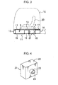
- FIGS. 1 to 7 show a construction machine according to a first embodiment, which machine comprises a cab noise reduction device including a resonator (also called "Helmholtz-type sound absorber") 21 as shown in FIG. 4 .
- the resonator 21 has a body portion 22, which is a hollow, rectangular parallelepiped-shaped box-like member, and a tubular-shaped neck portion 23.
- the body portion 22 has a sidewall surrounding an internal space, the sidewall formed with a through-hole at an appropriate position thereof.
- the neck portion 23 is fixed to the sidewall in such a manner as to surround the through-hole provided in the sidewall of the body portion 22 and protrude outwardly from the sidewall.
- the resonator 21 in the first embodiment having a resonance frequency of 400 Hz or less, for example, 200 Hz, is operable to reduce noise entering into the internal space of the body portion 22 through an opening 24 surrounded by the neck portion 23, by a resonance effect.
- the frequency of the sound that the resonator 21 can absorb depends on a sound velocity, a cross-sectional area and a length of the neck portion 23, and a volume of the body portion 22. Accordingly, designing dimensions of the respective portions of the resonator 21 section so as to make the frequency equal to a frequency of target noise can provide a sound-absorbing effect on the target noise to the resonator 21.
- the body portion 22 of the resonator 21 is not limited to the rectangular parallelepiped shape, but may be, for example, a circular cylindrical shape. Besides, it is also permitted that the resonator 21 would not have the neck portion 23 but simply have an opening provided in the sidewall of the body portion 22.
- the resonator 21 is disposed at an appropriate position within the under-cab space S.
- the resonator 21 is installed in at least one of (in the illustrated embodiment, each of) right and left opposite ends of opposed wall surfaces of the front and rear transverse frames 15 and 16 constituting the cab deck 11, i.e., four corners of the under-cab space S defined between the two transverse frames 15 and 16, in such a manner that the opening 24 is located in a vicinity of the wall surface and oriented toward the under-cab space S.
- the resonator 21 thus installed within the under-cab space S can reduce noise which would intrude from the outside into the cab through the aforementioned through-holes for a hydraulic pipe and others via the under-cab space S, in the under-cab space S. Furthermore, depending on the installation position, the resonator 21 can exert a high noise reduction effect.
- FIGS. 5A and 5B show respective sound pressure distributions at primary resonance in the widthwise direction and in the frontward-rearward direction of the cab in the under-cab space S between the front and rear transverse frames 15 and 16;
- FIGS. 6A and 6B show respective sound pressure distributions at secondary resonance in the widthwise direction and in the frontward-rearward direction of the cab in the under-cab space S.
- the four resonators 21 which are disposed in the respective four corners as in the first embodiment can exert a higher noise reduction effect.
- the resonator 21 may be installed on a wall surface of each of the left and right frame 13 and 14, instead of each of the front and rear transverse frames 15 and 16.
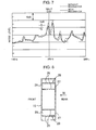
- FIG. 7 shows in result of a test carried out by the inventor to check the noise reduction effect in the first embodiment.
- the thick line indicates a noise level in the first embodiment
- the dashed line indicates a noise level in a hydraulic shovel devoid of the resonator 21.
- the body portion 22 of the resonator 21 has a size of 150 mm ⁇ 150 mm ⁇ 40 mm
- the neck portion 23 of the resonator 21 has a size of 40 mm in either of a diameter and a length.
- FIGS. 8 and 9 show a second embodiment of the present invention. This embodiment, focusing on a point that each of the front and rear transverse frames 15 and 16 of the cab deck 11 has a widthwisely-long, hollow, box-shaped structure whose periphery is substantially closed, includes forming a resonator by utilization of each of the transverse frames 15 and 16.
- FIGS. 8 and 9 shown is only the front transverse frame 15 representatively, in the two transverse frames 15 and 16.
- FIG. 8 is a horizontal sectional view of the front transverse frame 15
- FIG. 9 is a diagram (rear view) of the front transverse frame 15, when viewed from the arrowed line IX in FIG. 8 .
- the transverse frame 15 since the transverse frame 15 has a volume too large to form a resonator, there are provided a plurality of (in the illustrated embodiment, four) partition plates 25, --- inside the transverse frame 15 in side-by-side relation in a longitudinal direction thereof, to thereby define two independent closed spaces 26 and 26 in opposite end regions of an internal space of the transverse frame 15, respectively.
- the transverse frame 15 has a sidewall formed with two openings 27 to let each of the closed spaces 26 and 26 communicate with a space outside the transverse frame 15, i.e., the under-cab space S shown in FIGS. 1 to 3 .
- each of the resonators 28 and 28 is formed by a combination of the sidewall of the transverse frame 15 and the partition plates 25, ---.
- each of the openings 27 and 27 has a shape of including a semi-arc or generally semi-arc (e.g., semi-elliptical) shaped upper peripheral edge and a linear lower peripheral edge aligned with a lower edge of the transverse frame 15 as shown in FIG. 9 : this offers an advantage of avoiding significant deterioration in the strength of the transverse frame 15, despite the formation of the openings 27 and 27, facilitating machining of the openings 27 and 27, and preventing accumulation of rainwater inside the transverse frame 15.
- the opening 27 may, however, be formed in any other suitable shape, for example, a polygonal shape such as a quadrilateral shape, or a vertically-long or horizontally-long elliptical shape.
- FIG. 10 shows a third embodiment of the present invention.
- This embodiment includes a vertical partition plate 29, in addition to the partition plates 25, ---: the vertical partition plate 29 is so provided as to extend in the longitudinal direction of the transverse frame 15, i.e., the rightward-leftward direction of the hydraulic shovel, in a vertical posture, while intersecting with the partition plates 25, --- at a right angle, thereby further partitioning each of the closed spaces 26 and 26 into a front space 26a and a rear space 26b.
- a plurality of openings 27 each opened in the frontward-rearward direction are provided; thus a plurality of resonators 30, --- are formed.
- These resonators 30, --- are capable of lowering sound pressures in both of the two under-cab spaces S and S defined on the front and rear sides of the transverse frame 15 as shown in FIGS. 1 to 3 .
- FIG. 11 shows a fourth embodiment of the present invention.
- This embodiment includes a horizontal partition plate 29, in addition to the partition plates 25, ---: the horizontal partition plate 29 is so provided as to extend in the longitudinal direction of the transverse frame 15, i.e., the rightward-leftward direction of the hydraulic shovel, in a horizontal posture, while intersecting with the partition plates 25, --- at a right angle, thereby further partitioning each of the closed spaces 26 and 26 into an upper space 26c and a lower space 26d.
- a plurality of openings 27 each opened in the frontward-rearward direction are provided; thus a plurality of resonators 32, --- are formed.
- FIG. 12 shows a fifth embodiment of the present invention.
- This embodiment includes, in the longitudinal frame 15 shown in FIG. 8 , forming an opening 27' which continuously extends over an entire or approximately entire region in the longitudinal direction thereof, in place of the opening 27 consisting of a locally-formed through-hole in the longitudinal frame 15.
- the thus shaped opening 27' also allows the longitudinal frame 15 to be utilized as a body portion of a resonator.
- FIG. 13 shows a sixth embodiment of the present invention.
- This embodiment includes a resonator 33, which has a body portion formed by utilization of at least one of the mounting seats 17, --- shown in FIG. 2 (in the embodiment shown in FIG. 13 , the right and left front mounting seats 17 and 17), in place of or in addition to the resonator 21 in the cab deck 11 shown in FIG. 2 .
- the mounting seat 17 is formed in a hollow box-like shape having a top wall and a sidewall extending downwardly from the top wall to face the under-cab space S; the sidewall is provided with an opening 27 at its appropriate position so as to let an inside and an outside of the sidewall communicate with each other.
- the top wall of the mounting seat 17 constituting the resonator 33 is provided with a through-hole for attaching the cab mounting member so as to be also opened outside via the through-hole; however, the mounting seat 17 can sufficiently carry out a function as the body portion of the resonator 33, because the through-hole of the top wall will be closed by the cab mounting member attached to the top wall so as to allow the entire mounting seat to be finally a box-shaped structure whose periphery is substantially closed.
- the resonators 33 shown in FIG. 13 is constituted by only the right and left front mounting seats 17 and 17, the resonator 33 may also be constituted by each of the right and left rear mounting seat 17 and 17, or each of all of the mounting seats 17, ---.
- the cab noise reduction device in each of the second to sixth embodiments can exert the same effects as those of the cab noise reduction device in the first embodiment.
- the present invention provides a construction machine capable of effectively reducing noise which would intrude into a cab, without involving deterioration in ride quality, comfort and air-conditioning efficiency in the cab.
- the construction machine comprises a lower propelling body, an upper slewing body including an upper frame and slewably mounted on the lower propelling body, a cab including a floor plate and installed on the upper frame, and a cab noise reduction device.
- the cab noise reduction device comprises: the floor plate; an under-cab member including a cab deck supporting the cab and provided under the cab to define a closed-form under-cab space whose periphery is substantially closed, in cooperation with the floor plate; and a resonator provided in the under-cab space to reduce noise intruding into the under-cab space by a resonance effect.
- the resonator is preferably formed so as to have a resonance frequency equal to or less than 400 Hz. This resonance frequency provides a high actual advantage in reducing noise in the cab.
- the resonator preferably includes: a hollow body portion having a sidewall; and an opening provided in the sidewall of the body portion to let an internal space of the body portion and the under-cab space outside the body portion communicate with each other.
- the position of the resonator is determined by taking into account of a resonance state in the under-cab space, which enables a sound-absorbing effect based on the resonance effect of the resonator to be enhanced.
- a resonance phenomenon specific to dimensions of a space occurs, and a sound pressure becomes higher by the resonance; this resonance mode includes an anti-node having a high sound pressure and a node having a low sound pressure.
- the resonator under the following condition, can weaken the resonance phenomenon to efficiently lower a sound pressure in the entire under-cab space and thus lower a sound pressure around operator's ears in the cab;
- the condition is that the resonator is disposed at a position corresponding to the anti-node of the sound pressure (for example, a position adjacent to at least one of two or more wall surfaces partially surrounding the under-cab space and facing the position corresponding to the anti-node of the sound pressure, more preferably, a position of at least one of a plurality of corners of the under-cab space at respective ends of the wall surfaces).
- the under-cab member has a hollow box-shaped portion whose periphery is substantially closed, it is possible to form a resonator including the hollow box-shaped portion as the body portion thereof by providing an opening in the hollow box-shaped portion.
- the under-cab member may include a hollow box-shaped frame extending in a rightward-leftward direction or a frontward-rearward direction of the construction machine, and a partition plate which partitions an internal space of the box-shaped frame into a plurality of spaces to form the body portion in cooperation with the box-shaped frame.
- the under-cab member may include a plurality of mounting seats each having a cab mounting member attached thereonto to support the cab from lower side thereof, at least one of the mounting seats being formed into a hollow box shape whose periphery is substantially closed, to form the body portion.
Landscapes
- Engineering & Computer Science (AREA)
- Civil Engineering (AREA)
- Combustion & Propulsion (AREA)
- Transportation (AREA)
- Mechanical Engineering (AREA)
- Mining & Mineral Resources (AREA)
- Chemical & Material Sciences (AREA)
- General Engineering & Computer Science (AREA)
- Structural Engineering (AREA)
- Physics & Mathematics (AREA)
- Acoustics & Sound (AREA)
- Multimedia (AREA)
- Component Parts Of Construction Machinery (AREA)
- Body Structure For Vehicles (AREA)
Abstract
Description
- The present invention relates to a construction machine, such as a hydraulic shovel, which comprises a cab and a cab noise reduction device for suppressing the intrusion of noise into the cab.
- The background art of the present invention will be described by taking a hydraulic shovel as an example.
-
FIG. 14 shows a hydraulic shovel which is a conventional construction machine. This hydraulic shovel comprises a crawler type lower propelling body 1, anupper slewing body 2 mounted on the lower propelling body 1 slewably about a vertical axis thereof, and anattachment 6 attached to theupper slewing body 2, wherein theattachment 6 includes aboom 3, an arm 4 and abucket 5. - The
upper slewing body 2 includes anupper frame 7 as a base, which has a rear portion on which an engine room 9 for accommodating an engine 8 therein is provided, and a front portion on which acab 10 is installed to allow an operator to perform various operations thereinside. In this specification, each of the terms "front (frontward)", "rear (rearward)", "left (leftward)" and "right (rightward)" means a direction as viewed from an operator seated in thecab 10. -
FIGS. 15 to 17 show an arrangement around theupper frame 7 and thecab 10. - The
upper frame 7 includes acab deck 11, on which thecab 10 is installed. Thecab deck 11 has afront frame 12 extending widthwise of the hydraulic shovel, aleft frame 12 and aright frame 13 connected to respective ones of left and right ends of thefront frame 12, and twotransverse frame front frame 12 while being offset with respect to each other in a frontward-rearward direction so as to couple the left andright frames cab deck 11 being formed in a generally ladder structure as a whole. Thecab deck 11 has right and left corners on opposite sides of front and rear ends, i.e., four corners, which have respective inner surfaces to which fourmounting seats 17,--- are attached respectively. Onto themounting seats 17,--- are attached non-illustrated four cab mounting members respectively. Thecab 10 is supported on the cab mounting members. - The
cab deck 11 has a lower surface, to which front and rear undercovers 18 shown inFIG. 17 are attached so as to close an opening defined between thefront frame 12 and the fronttransverse frame 15 and an opening defined between the front and reartransverse frames cab 10 includes afloor plate 19 constituting a floor of thecab 10, thefloor plate 19 closing the openings from thereabove. Thecab 10 is provided with acab seat 20 shown inFIG. 17 therein. - The
cab deck 11 and theundercovers floor plate 19 of thecab 10, surrounding two under-cab spaces S and S located on front and rear sides of thelongitudinal frame 15 respectively. Each of the under-cab spaces S and S is a closed space whose periphery is substantially closed, allowing a hydraulic pipe, a wiring and the like to be passed through the under-cab spaces S and S. Thecab deck 11 including themounting seats 17, and the undercovers 18 and 18, constitute an "under-cab member" disposed under thecab 10. - While, as mentioned above, each of the under-cab spaces S and S is fundamentally a closed space whose periphery is closed, each of the
floor plate 19, thecab deck 11 and theundercovers cab 10, and therefore permit operating noise, such as engine noise, pump noise and fan noise, to intrude into thecab 10 from the outside via the under-cab spaces S and S, thus causing an operator to feel uncomfortable. - As means for preventing the intrusion of noise into a cab, there have been known techniques disclosed in the following
Patent Documents 1 and 2. - The technique disclosed in the Patent Document 1 includes providing a space isolation layer inside a cab with respect to each of a floor and a roof thereof. Each of the space isolation layers reduces a real height of the internal space of the cab to thereby heighten a resonance frequency of the internal space of the cab, while functioning as a noise-absorbing air layer interposed between the space isolation layer and an outer panel.
- On the other hand, the technique disclosed in the
Patent Document 2 includes providing a sound release hole in a peripheral wall (e.g., a pillar) of a cab to let a back-pressure inside a cab therethrough. - In addition, there has been known a technique disclosed in the following
Patent Document 3, as a publicly known technique for suppressing noise not intruding into a cab but released outside a machine. This technique includes a box-shaped member which constitutes an upper frame, the box-shaped member provided with an opening and a neck portion to thereby form a resonator. This resonator has a resonance effect which can reduce low-frequency noise particularly. - The above publicly known techniques, however, have the following problems. The technique described in the Patent Document 1 involves a reduction in the real height of the internal space of the cab, which deteriorates ride quality and comfort of the cab. The technique described in the
Patent Document 2 involves that the sound release hole for positively communicating between an inside and an outside of the cab would lower air-conditioning efficiency. The technique described in thePatent Document 3 is incapable of suppressing the intrusion of noise into a cab. -
- Patent Document 1:
JP 8-81976A - Patent Document 2:
JP 2003-268805A - Patent Document 3:
JP-U 3-59223A - It is an object of the present invention to provide a construction machine comprising a cab noise reduction device capable of effectively reducing noise intruding into a cab, without involving deterioration in ride quality, comfort and air-conditioning efficiency in the cab. This construction machine comprises: a lower propelling body; an upper slewing body including an upper frame and slewably mounted on the lower propelling body; a cab including a floor plate and being installed on the upper frame; and a cab noise reduction device. The cab noise reduction device comprises: the floor plate; an under-cab member which includes a cab deck supporting the cab and is provided under the cab to thereby define a closed-form under-cab space whose periphery is substantially closed, in cooperation with the floor plate; and a resonator which is provided in the under-cab space and reduces noise intruding into the under-cab space, by a resonance effect.
-
-
FIG. 1 is a top plan view showing a cab noise reduction device provided in a construction machine according to a first embodiment of the present invention. -
FIG. 2 is a perspective view of the cab noise reduction device. -
FIG. 3 is a side sectional view of the cab noise reduction device. -
FIG. 4 is a perspective view of a resonator constituting the cab noise reduction device. -
FIG. 5A is a diagram showing a sound pressure distribution at primary resonance in a widthwise direction in an under-cab space of the cab noise reduction device. -
FIG. 5B is a diagram showing a sound pressure distribution at primary resonance in a frontward-rearward direction in the under-cab space. -
FIG. 6A is a diagram showing a sound pressure distribution at secondary resonance in the under-cab space of the cab noise reduction device. -
FIG. 6B is a diagram showing a sound pressure distribution at secondary resonance in the frontward-rearward direction in the under-cab space. -
FIG. 7 is a chart showing a test result on a noise reduction effect of the cab noise reduction device. -
FIG. 8 is a horizontal sectional view of a transverse frame of a cab deck in a second embodiment of the present invention. -
FIG. 9 is a diagram of the transverse frame of the cab deck, when viewed from the arrowed line IX inFIG. 8 . -
FIG. 10 is a horizontal sectional view of a transverse frame of a cab deck in a third embodiment of the present invention. -
FIG. 11 is a horizontal sectional view of a transverse frame of a cab deck in a fourth embodiment of the present invention. -
FIG. 12 is a horizontal sectional view of a transverse frame of a cab deck in a fifth embodiment of the present invention. -
FIG. 13 is a perspective view of a cab noise reduction device in a sixth embodiment of the present invention. -
FIG. 14 is a schematic side view of a hydraulic shovel which is one example of a subject matter of the present invention. -
FIG. 15 is a fragmentary top plan view of a conventional upper frame constituting the hydraulic shovel and including a cab deck. -
FIG. 16 is a perspective view of the cab deck shown inFIG. 15 . -
FIG. 17 is a sectional side view of an under-cab member including the cab deck shown inFIG. 15 . - With reference to
FIGS. 1 to 13 , there will be described various embodiments according to the present invention. The following embodiments are examples where the present invention is applied to the aforementioned type of hydraulic shovel shown inFIG. 14 . The specific structure of the hydraulic shovel according to each of the following embodiments is common to the conventional structure shown inFIGS. 15 to 17 , in the following points A to D. - A. The
upper frame 7 shown inFIG. 14 includes acab deck 11, on which acab 10 is installed. - B. The
cab deck 11 includes afront frame 12, aleft frame 13 and aright frame 14 which frames are assembled together to form a box structure, and front and reartransverse frames entire cab deck 11 being formed into a generally ladder structure. Thecab deck 11 has four corners on right and left sides of front and rear ends, the ends having respective inner surfaces to which four mountingseats 17, --- are provided respectively. Onto each of the mountingseats 17, ---, there are attached non-illustrated respective four cab mounting members, on which thecab 10 is supported. - C. The
cab deck 11 has a lower surface, to which twoundercovers front frame 12 and the fronttransverse frame 15, and an opening between the twotransverse frames cab 10 shown inFIG. 14 includes afloor plate 19 constituting a floor of thecab 10 and closing the openings from upper side thereof. - D. The
cab deck 11, theundercovers floor plate 19 define two under-cab spaces S and S under thecab 10. Each of the under-cab spaces S and S is a substantially closed space in a frontward-rearward direction, a rightward-leftward (widthwise) direction and an upward-downward direction, and a hydraulic pipe, through which spaces a wiring and the like are passed. - The first embodiment will be described while assigning the same reference number or code as that in
FIGS. 14 to 17 to the same element or component as that shown inFIGS. 14 to 17 , as well as those described in the A to D, and omitting its duplicated description. -
FIGS. 1 to 7 show a construction machine according to a first embodiment, which machine comprises a cab noise reduction device including a resonator (also called "Helmholtz-type sound absorber") 21 as shown inFIG. 4 . Theresonator 21 has abody portion 22, which is a hollow, rectangular parallelepiped-shaped box-like member, and a tubular-shapedneck portion 23. Thebody portion 22 has a sidewall surrounding an internal space, the sidewall formed with a through-hole at an appropriate position thereof. Theneck portion 23 is fixed to the sidewall in such a manner as to surround the through-hole provided in the sidewall of thebody portion 22 and protrude outwardly from the sidewall. - The
resonator 21 in the first embodiment, having a resonance frequency of 400 Hz or less, for example, 200 Hz, is operable to reduce noise entering into the internal space of thebody portion 22 through anopening 24 surrounded by theneck portion 23, by a resonance effect. The frequency of the sound that theresonator 21 can absorb depends on a sound velocity, a cross-sectional area and a length of theneck portion 23, and a volume of thebody portion 22. Accordingly, designing dimensions of the respective portions of theresonator 21 section so as to make the frequency equal to a frequency of target noise can provide a sound-absorbing effect on the target noise to theresonator 21. Thebody portion 22 of theresonator 21 is not limited to the rectangular parallelepiped shape, but may be, for example, a circular cylindrical shape. Besides, it is also permitted that theresonator 21 would not have theneck portion 23 but simply have an opening provided in the sidewall of thebody portion 22. - The
resonator 21 is disposed at an appropriate position within the under-cab space S. In the first embodiment, as shown inFIGS. 1 to 3 , theresonator 21 is installed in at least one of (in the illustrated embodiment, each of) right and left opposite ends of opposed wall surfaces of the front and reartransverse frames cab deck 11, i.e., four corners of the under-cab space S defined between the twotransverse frames opening 24 is located in a vicinity of the wall surface and oriented toward the under-cab space S. - The
resonator 21 thus installed within the under-cab space S can reduce noise which would intrude from the outside into the cab through the aforementioned through-holes for a hydraulic pipe and others via the under-cab space S, in the under-cab space S. Furthermore, depending on the installation position, theresonator 21 can exert a high noise reduction effect. - This point will be specifically described.
FIGS. 5A and 5B show respective sound pressure distributions at primary resonance in the widthwise direction and in the frontward-rearward direction of the cab in the under-cab space S between the front and reartransverse frames FIGS. 6A and 6B show respective sound pressure distributions at secondary resonance in the widthwise direction and in the frontward-rearward direction of the cab in the under-cab space S. These figures show that, in the under-cab space S defined between the front and reartransverse frames transverse frames resonators 21 will be able to effectively suppress a resonance in the under-cab space S to significantly lower the sound pressure, thus reducing noise around operator's ears, when disposed so as to position theopening 24 thereof in the corner corresponding to the position of the anti-node of the sound pressure. Particularly, the fourresonators 21 which are disposed in the respective four corners as in the first embodiment can exert a higher noise reduction effect. Theresonator 21 may be installed on a wall surface of each of the left andright frame transverse frames -
FIG. 7 shows in result of a test carried out by the inventor to check the noise reduction effect in the first embodiment. InFIG. 7 , the thick line indicates a noise level in the first embodiment, while the dashed line indicates a noise level in a hydraulic shovel devoid of theresonator 21. In either case, thebody portion 22 of theresonator 21 has a size of 150 mm × 150 mm × 40 mm, and theneck portion 23 of theresonator 21 has a size of 40 mm in either of a diameter and a length. The test result shown inFIG. 7 indicates that installing four of theresonators 21 in the respective four corners enables a noise level around an operator's right ear during no load to be reduced by about 5 db, on the target frequency of 200 Hz. This noise reduction effect can also be obtained to some extent in the case where theresonator 21 is installed in each of only two of the four corners or installed at a position closer to a center of the transverse frame than to the corner. - Furthermore, as for another frequency of noise, it is possible to obtain a similar noise reduction effect fundamentally, when the dimensions of the
body portion 22 and theneck portion 23 are set based on the frequency. However, in the case of hydraulic shovels, it is desirable to set the target frequency to a value of 400 Hz or less, in which frequency the resonance in the cab can perform a great influence. -
FIGS. 8 and9 show a second embodiment of the present invention. This embodiment, focusing on a point that each of the front and reartransverse frames cab deck 11 has a widthwisely-long, hollow, box-shaped structure whose periphery is substantially closed, includes forming a resonator by utilization of each of thetransverse frames - In
FIGS. 8 and9 , shown is only the fronttransverse frame 15 representatively, in the twotransverse frames FIG. 8 is a horizontal sectional view of the fronttransverse frame 15, andFIG. 9 is a diagram (rear view) of the fronttransverse frame 15, when viewed from the arrowed line IX inFIG. 8 . - In the second embodiment, since the
transverse frame 15 has a volume too large to form a resonator, there are provided a plurality of (in the illustrated embodiment, four)partition plates 25, --- inside thetransverse frame 15 in side-by-side relation in a longitudinal direction thereof, to thereby define two independentclosed spaces transverse frame 15, respectively. Besides, thetransverse frame 15 has a sidewall formed with twoopenings 27 to let each of theclosed spaces transverse frame 15, i.e., the under-cab space S shown inFIGS. 1 to 3 . Thus easily formed are tworesonators closed spaces transverse frame 15. In short, the body portion of each of theresonators transverse frame 15 and thepartition plates 25, ---. - In the second embodiment, each of the
partition plates 25, --- additionally functioning as a reinforcing member for increasing rigidity and strength of thetransverse frame 15, suppresses vibration of thetransverse frame 15 itself. In this case, it is preferable that each of theopenings transverse frame 15 as shown inFIG. 9 : this offers an advantage of avoiding significant deterioration in the strength of thetransverse frame 15, despite the formation of theopenings openings transverse frame 15. - The
opening 27 may, however, be formed in any other suitable shape, for example, a polygonal shape such as a quadrilateral shape, or a vertically-long or horizontally-long elliptical shape. -
FIG. 10 shows a third embodiment of the present invention. This embodiment includes avertical partition plate 29, in addition to thepartition plates 25, ---: thevertical partition plate 29 is so provided as to extend in the longitudinal direction of thetransverse frame 15, i.e., the rightward-leftward direction of the hydraulic shovel, in a vertical posture, while intersecting with thepartition plates 25, --- at a right angle, thereby further partitioning each of theclosed spaces front space 26a and arear space 26b. In association with the respective partitioned spaces, a plurality ofopenings 27 each opened in the frontward-rearward direction are provided; thus a plurality ofresonators 30, --- are formed. Theseresonators 30, --- are capable of lowering sound pressures in both of the two under-cab spaces S and S defined on the front and rear sides of thetransverse frame 15 as shown inFIGS. 1 to 3 . -
FIG. 11 shows a fourth embodiment of the present invention. This embodiment includes ahorizontal partition plate 29, in addition to thepartition plates 25, ---: thehorizontal partition plate 29 is so provided as to extend in the longitudinal direction of thetransverse frame 15, i.e., the rightward-leftward direction of the hydraulic shovel, in a horizontal posture, while intersecting with thepartition plates 25, --- at a right angle, thereby further partitioning each of theclosed spaces upper space 26c and alower space 26d. In association with the respective partitioned spaces, a plurality ofopenings 27 each opened in the frontward-rearward direction are provided; thus a plurality ofresonators 32, --- are formed. -
FIG. 12 shows a fifth embodiment of the present invention. This embodiment includes, in thelongitudinal frame 15 shown inFIG. 8 , forming an opening 27' which continuously extends over an entire or approximately entire region in the longitudinal direction thereof, in place of theopening 27 consisting of a locally-formed through-hole in thelongitudinal frame 15. The thus shaped opening 27' also allows thelongitudinal frame 15 to be utilized as a body portion of a resonator. -
FIG. 13 shows a sixth embodiment of the present invention. This embodiment includes aresonator 33, which has a body portion formed by utilization of at least one of the mountingseats 17, --- shown inFIG. 2 (in the embodiment shown inFIG. 13 , the right and leftfront mounting seats 17 and 17), in place of or in addition to theresonator 21 in thecab deck 11 shown inFIG. 2 . Specifically, the mountingseat 17 is formed in a hollow box-like shape having a top wall and a sidewall extending downwardly from the top wall to face the under-cab space S; the sidewall is provided with anopening 27 at its appropriate position so as to let an inside and an outside of the sidewall communicate with each other. - In the embodiment shown in
FIG. 13 , the top wall of the mountingseat 17 constituting theresonator 33 is provided with a through-hole for attaching the cab mounting member so as to be also opened outside via the through-hole; however, the mountingseat 17 can sufficiently carry out a function as the body portion of theresonator 33, because the through-hole of the top wall will be closed by the cab mounting member attached to the top wall so as to allow the entire mounting seat to be finally a box-shaped structure whose periphery is substantially closed. - While the
resonators 33 shown inFIG. 13 is constituted by only the right and leftfront mounting seats resonator 33 may also be constituted by each of the right and leftrear mounting seat seats 17, ---. - Fundamentally, the cab noise reduction device in each of the second to sixth embodiments can exert the same effects as those of the cab noise reduction device in the first embodiment.
- As above, the present invention provides a construction machine capable of effectively reducing noise which would intrude into a cab, without involving deterioration in ride quality, comfort and air-conditioning efficiency in the cab. The construction machine comprises a lower propelling body, an upper slewing body including an upper frame and slewably mounted on the lower propelling body, a cab including a floor plate and installed on the upper frame, and a cab noise reduction device. The cab noise reduction device comprises: the floor plate; an under-cab member including a cab deck supporting the cab and provided under the cab to define a closed-form under-cab space whose periphery is substantially closed, in cooperation with the floor plate; and a resonator provided in the under-cab space to reduce noise intruding into the under-cab space by a resonance effect.
- In this construction machine, defining the under-cab space under the cab and providing the resonator utilizing the resonance effect in the under-cab space makes it possible to lower a sound pressure in the under-cab space and consequently lower a sound pressure in the cab, without influencing ride quality, comfort and air-conditioning efficiency in the cab.
- The resonator is preferably formed so as to have a resonance frequency equal to or less than 400 Hz. This resonance frequency provides a high actual advantage in reducing noise in the cab.
- The resonator preferably includes: a hollow body portion having a sidewall; and an opening provided in the sidewall of the body portion to let an internal space of the body portion and the under-cab space outside the body portion communicate with each other.
- More preferably, the position of the resonator is determined by taking into account of a resonance state in the under-cab space, which enables a sound-absorbing effect based on the resonance effect of the resonator to be enhanced. Specifically, in the under-cab space, a resonance phenomenon specific to dimensions of a space occurs, and a sound pressure becomes higher by the resonance; this resonance mode includes an anti-node having a high sound pressure and a node having a low sound pressure. In the case where the under-cab space is defined between two opposed wall surfaces, there will be occurred a resonance mode in which an anti-node where the sound pressure is maximized exists at a position adjacent to each of the wall surfaces (particularly, in a vicinity of each of opposite ends of the wall surface, i.e., each of four corners of the under-cab space), and several nodes exist at respective positions between the anti-nodes. In this case, the resonator, under the following condition, can weaken the resonance phenomenon to efficiently lower a sound pressure in the entire under-cab space and thus lower a sound pressure around operator's ears in the cab; the condition is that the resonator is disposed at a position corresponding to the anti-node of the sound pressure (for example, a position adjacent to at least one of two or more wall surfaces partially surrounding the under-cab space and facing the position corresponding to the anti-node of the sound pressure, more preferably, a position of at least one of a plurality of corners of the under-cab space at respective ends of the wall surfaces).
- In the case where the under-cab member has a hollow box-shaped portion whose periphery is substantially closed, it is possible to form a resonator including the hollow box-shaped portion as the body portion thereof by providing an opening in the hollow box-shaped portion. For example, the under-cab member may include a hollow box-shaped frame extending in a rightward-leftward direction or a frontward-rearward direction of the construction machine, and a partition plate which partitions an internal space of the box-shaped frame into a plurality of spaces to form the body portion in cooperation with the box-shaped frame. The addition of the partition plate makes it possible to easily establish a resonator with a body portion having an optimal volume for obtaining a noise reduction effect at a desired frequency, irrespective of a size of the box-shaped frame. Alternatively, the under-cab member may include a plurality of mounting seats each having a cab mounting member attached thereonto to support the cab from lower side thereof, at least one of the mounting seats being formed into a hollow box shape whose periphery is substantially closed, to form the body portion.
Claims (10)
- A construction machine which comprises:a lower propelling body;an upper slewing body including an upper frame and slewably mounted on the lower propelling body;a cab including a floor plate and being installed on the upper frame;and a cab noise reduction device, the cab noise reduction device comprising:the floor plate;an under-cab member including a cab deck supporting the cab and being provided under the cab to define a closed-form under-cab space whose periphery is substantially closed, in cooperation with the floor plate; anda resonator provided in the under-cab space to reduce noise intruding into the under-cab space by a resonance effect.
- The construction machine as defined in claim 1, wherein the resonator includes: a hollow body portion having a sidewall; and an opening provided in the sidewall of the body portion to let an internal space of the body portion and the under-cab space outside the body portion communicate with each other through the opening.
- The construction machine as defined in claim 2, wherein the resonator is disposed so as to locate the opening thereof in at least one of a plurality of positions corresponding to respective anti-nodes of a sound pressure at resonance in the under-cab space.
- The construction machine as defined in claim 3, wherein the resonator is disposed so as to locate the opening thereof adjacent to at least one of two or more wall surfaces partially defining the under-cab space and facing the anti-nodes of the sound pressure.
- The construction machine as defined in claim 4, wherein the resonator is disposed so as to locate the opening thereof in at least one of a plurality of corners of the under-cab space at respective ends of the wall surfaces.
- The construction machine as defined in claim 5, wherein the resonator is disposed at each of a plurality of positions so as to locate the opening in each of all the corners of the under-cab space at the ends of the wall surfaces.
- The construction machine as defined in claim 2, wherein the under-cab member has a hollow box-shaped portion whose periphery is substantially closed, and wherein an opening is provided in the hollow box-shaped portion to form the resonator including the hollow box-shaped portion as the body portion.
- The construction machine as defined in claim 7, wherein the under-cab member includes: a box-shaped frame extending in a rightward-leftward direction or a frontward-rearward direction of the construction machine; and a partition plate which partitions an internal space of the box-shaped frame into a plurality of spaces to form the body portion in cooperation with the box-shaped frame.
- The construction machine as defined in claim 7, wherein the under-cab member includes a plurality of mounting seats each having a cab mounting member attached thereonto to support the cab from lower side thereof, and wherein at least one of the mounting seats is formed into a hollow box shape whose periphery is substantially closed, to form the body portion.
- The construction machine as defined in any one of claims 1 to 9, wherein the resonator is formed so as to have a resonance frequency equal to or less than 400 Hz.
Applications Claiming Priority (2)
| Application Number | Priority Date | Filing Date | Title |
|---|---|---|---|
| JP2008254626A JP5108709B2 (en) | 2008-09-30 | 2008-09-30 | Cabin soundproofing equipment for construction machinery |
| PCT/JP2009/065630 WO2010038585A1 (en) | 2008-09-30 | 2009-09-08 | Construction machine with device for acoustically insulating cabin |
Publications (3)
| Publication Number | Publication Date |
|---|---|
| EP2341192A1 true EP2341192A1 (en) | 2011-07-06 |
| EP2341192A4 EP2341192A4 (en) | 2014-01-15 |
| EP2341192B1 EP2341192B1 (en) | 2015-03-11 |
Family
ID=42073356
Family Applications (1)
| Application Number | Title | Priority Date | Filing Date |
|---|---|---|---|
| EP09817622.5A Not-in-force EP2341192B1 (en) | 2008-09-30 | 2009-09-08 | Construction machine with device for acoustically insulating cabin |
Country Status (5)
| Country | Link |
|---|---|
| US (1) | US8590668B2 (en) |
| EP (1) | EP2341192B1 (en) |
| JP (1) | JP5108709B2 (en) |
| CN (1) | CN102171396B (en) |
| WO (1) | WO2010038585A1 (en) |
Cited By (1)
| Publication number | Priority date | Publication date | Assignee | Title |
|---|---|---|---|---|
| EP2551411A3 (en) * | 2011-07-27 | 2017-01-04 | Kobelco Construction Machinery Co., Ltd. | Method and apparatus for mounting device in construction machine |
Families Citing this family (10)
| Publication number | Priority date | Publication date | Assignee | Title |
|---|---|---|---|---|
| FR2959056B1 (en) * | 2010-04-16 | 2015-05-29 | Hutchinson | ACOUSTIC INSULATION DEVICE AND METHOD FOR MANUFACTURING THE SAME |
| JP5706110B2 (en) * | 2010-07-29 | 2015-04-22 | プレス工業株式会社 | Cab frame structure of construction machinery |
| JP5866172B2 (en) * | 2011-10-14 | 2016-02-17 | 株式会社神戸製鋼所 | Translucent sound absorbing panel |
| JP6174969B2 (en) * | 2013-10-29 | 2017-08-02 | キャタピラー エス エー アール エル | Construction machinery cab support structure |
| CN104859728B (en) * | 2015-06-10 | 2017-03-01 | 湘电重型装备有限公司 | A kind of electric power wheel self-discharging vehicle driver's cabin with mute function |
| JP6311733B2 (en) * | 2016-02-23 | 2018-04-18 | コベルコ建機株式会社 | Deck under cabin |
| US20180174566A1 (en) * | 2016-12-19 | 2018-06-21 | Caterpillar Inc. | Compact acoustic resonator for enclosed systems |
| JP7310120B2 (en) * | 2018-11-05 | 2023-07-19 | ヤマハ株式会社 | sound absorbing structure |
| KR102575186B1 (en) * | 2018-12-07 | 2023-09-05 | 현대자동차 주식회사 | Device for reducing vibratie of sound meta sturcutre |
| CN113205791A (en) * | 2021-04-21 | 2021-08-03 | 中车株洲电力机车有限公司 | Rail transit vehicle, cab and noise control method of cab |
Citations (5)
| Publication number | Priority date | Publication date | Assignee | Title |
|---|---|---|---|---|
| US3954150A (en) * | 1975-01-29 | 1976-05-04 | Caterpillar Tractor Co. | Vehicle roll protective structure |
| JP2003082705A (en) * | 2001-09-10 | 2003-03-19 | Hitachi Constr Mach Co Ltd | Turning frame of construction machine and its of manufacturing method |
| US20040217630A1 (en) * | 2003-04-10 | 2004-11-04 | Yasuhiko Takeuchi | Operator's room for work machine |
| US20050098379A1 (en) * | 2003-10-09 | 2005-05-12 | Takahiko Sato | Noise absorbing structure and noise absorbing/insulating structure |
| EP1800955A2 (en) * | 2005-12-22 | 2007-06-27 | Deere & Company | Vehicle cab noise suppressing system |
Family Cites Families (19)
| Publication number | Priority date | Publication date | Assignee | Title |
|---|---|---|---|---|
| US4445584A (en) * | 1978-04-12 | 1984-05-01 | Nissan Motor Co., Ltd. | Motor vehicle equipped with engine noise emission preventing device |
| US4496188A (en) * | 1983-01-13 | 1985-01-29 | A G Motor Corp. | Floating cab |
| JPS61188660A (en) | 1985-02-18 | 1986-08-22 | Mitsubishi Electric Corp | Voice producing device for pos terminal |
| JPH0519397Y2 (en) * | 1985-05-16 | 1993-05-21 | ||
| JPH0359223A (en) | 1989-07-25 | 1991-03-14 | Kazuhiko Yamazaki | Foundation constructing method for reinforced concrete building |
| JPH0359223U (en) * | 1989-10-17 | 1991-06-11 | ||
| JPH0881976A (en) | 1994-09-09 | 1996-03-26 | Shin Caterpillar Mitsubishi Ltd | Cab for construction equipment |
| JP3510081B2 (en) * | 1996-05-09 | 2004-03-22 | コベルコ建機株式会社 | Hydraulic working machine |
| KR100294480B1 (en) * | 1996-06-04 | 2001-09-17 | 세구치 류이치 | Operator attachment machine |
| US5906411A (en) * | 1997-06-20 | 1999-05-25 | New Holland North America, Inc. | Combine harvester cab layout for visibility, serviceability and space |
| US5911624A (en) * | 1998-06-17 | 1999-06-15 | New Holland North America, Inc. | Combine harvester cab environment system |
| JP4215329B2 (en) * | 1999-01-29 | 2009-01-28 | 株式会社小松製作所 | Construction machine noise reduction device |
| JP4026985B2 (en) * | 1999-06-17 | 2007-12-26 | 株式会社小松製作所 | Noise reduction structure for work vehicle cab |
| JP2003268805A (en) | 2002-03-18 | 2003-09-25 | Kobelco Contstruction Machinery Ltd | Driver's cab structure of construction machinery |
| US7559601B2 (en) * | 2003-03-04 | 2009-07-14 | Hitachi Construction Machinery Co., Ltd. | Construction machine |
| DE602004017208D1 (en) | 2003-10-31 | 2008-11-27 | Dow Global Technologies Inc | SILENCING SYSTEM |
| JP2006077640A (en) * | 2004-09-08 | 2006-03-23 | Hitachi Constr Mach Co Ltd | Noise reduction device for construction machine |
| ATE417968T1 (en) * | 2005-05-27 | 2009-01-15 | Volvo Compact Equipment Sas | HYDRAULIC CIRCUIT FOR A PUBLIC WORKS VEHICLE AND VEHICLE COMPRISING SUCH A CIRCUIT. |
| KR100689293B1 (en) * | 2005-07-25 | 2007-03-02 | 볼보 컨스트럭션 이키프먼트 홀딩 스웨덴 에이비 | Cab support vehicle frame structure for construction machinery |
-
2008
- 2008-09-30 JP JP2008254626A patent/JP5108709B2/en not_active Expired - Fee Related
-
2009
- 2009-09-08 WO PCT/JP2009/065630 patent/WO2010038585A1/en active Application Filing
- 2009-09-08 EP EP09817622.5A patent/EP2341192B1/en not_active Not-in-force
- 2009-09-08 CN CN200980139606.0A patent/CN102171396B/en not_active Expired - Fee Related
- 2009-09-08 US US13/062,871 patent/US8590668B2/en not_active Expired - Fee Related
Patent Citations (5)
| Publication number | Priority date | Publication date | Assignee | Title |
|---|---|---|---|---|
| US3954150A (en) * | 1975-01-29 | 1976-05-04 | Caterpillar Tractor Co. | Vehicle roll protective structure |
| JP2003082705A (en) * | 2001-09-10 | 2003-03-19 | Hitachi Constr Mach Co Ltd | Turning frame of construction machine and its of manufacturing method |
| US20040217630A1 (en) * | 2003-04-10 | 2004-11-04 | Yasuhiko Takeuchi | Operator's room for work machine |
| US20050098379A1 (en) * | 2003-10-09 | 2005-05-12 | Takahiko Sato | Noise absorbing structure and noise absorbing/insulating structure |
| EP1800955A2 (en) * | 2005-12-22 | 2007-06-27 | Deere & Company | Vehicle cab noise suppressing system |
Non-Patent Citations (1)
| Title |
|---|
| See also references of WO2010038585A1 * |
Cited By (1)
| Publication number | Priority date | Publication date | Assignee | Title |
|---|---|---|---|---|
| EP2551411A3 (en) * | 2011-07-27 | 2017-01-04 | Kobelco Construction Machinery Co., Ltd. | Method and apparatus for mounting device in construction machine |
Also Published As
| Publication number | Publication date |
|---|---|
| EP2341192A4 (en) | 2014-01-15 |
| CN102171396B (en) | 2014-04-16 |
| CN102171396A (en) | 2011-08-31 |
| JP5108709B2 (en) | 2012-12-26 |
| US8590668B2 (en) | 2013-11-26 |
| US20110162908A1 (en) | 2011-07-07 |
| EP2341192B1 (en) | 2015-03-11 |
| WO2010038585A1 (en) | 2010-04-08 |
| JP2010084428A (en) | 2010-04-15 |
Similar Documents
| Publication | Publication Date | Title |
|---|---|---|
| EP2341192B1 (en) | Construction machine with device for acoustically insulating cabin | |
| BRPI0618190A2 (en) | vehicle body bottom structure | |
| US8733824B2 (en) | Construction machine with upper slewing body | |
| KR100689937B1 (en) | Rotating frame structure for construction machinery | |
| JP4888746B2 (en) | Oil pan structure | |
| JP5582167B2 (en) | Construction machinery | |
| EP1531115B1 (en) | Automotive floor panel structure | |
| JP2003211978A (en) | Shock absorbing structure of car body engine mounting part | |
| US10494038B2 (en) | Upper slewing body | |
| KR100412829B1 (en) | an engine mounting structure on a front side member of vehicles | |
| JP2011111103A (en) | Vibration control cabin type working vehicle | |
| EP2664716B1 (en) | Cab for a construction machine | |
| JP6922960B2 (en) | Construction machinery | |
| JP2014122008A (en) | Vehicle body front structure | |
| JP4146675B2 (en) | Car floor structure | |
| JP2003268805A (en) | Driver's cab structure of construction machinery | |
| WO2013179755A1 (en) | Construction machine | |
| JP2000233881A (en) | Elevator car | |
| JPH06136787A (en) | Working machine with operation room | |
| JP5225613B2 (en) | Work machine counterweight | |
| JP5929236B2 (en) | Work machine | |
| KR20040016256A (en) | Structure for preventing vibration of package tray center panel | |
| JP2021160509A (en) | Lower structure of electric vehicle | |
| JPH1134931A (en) | Vibration control structure of back panel for automobile | |
| JP5083904B2 (en) | Door equipment |
Legal Events
| Date | Code | Title | Description |
|---|---|---|---|
| PUAI | Public reference made under article 153(3) epc to a published international application that has entered the european phase |
Free format text: ORIGINAL CODE: 0009012 |
|
| 17P | Request for examination filed |
Effective date: 20110308 |
|
| AK | Designated contracting states |
Kind code of ref document: A1 Designated state(s): AT BE BG CH CY CZ DE DK EE ES FI FR GB GR HR HU IE IS IT LI LT LU LV MC MK MT NL NO PL PT RO SE SI SK SM TR |
|
| AX | Request for extension of the european patent |
Extension state: AL BA RS |
|
| DAX | Request for extension of the european patent (deleted) | ||
| A4 | Supplementary search report drawn up and despatched |
Effective date: 20131216 |
|
| RIC1 | Information provided on ipc code assigned before grant |
Ipc: G10K 11/16 20060101ALI20131210BHEP Ipc: E02F 9/16 20060101AFI20131210BHEP Ipc: B60R 13/08 20060101ALI20131210BHEP |
|
| GRAP | Despatch of communication of intention to grant a patent |
Free format text: ORIGINAL CODE: EPIDOSNIGR1 |
|
| INTG | Intention to grant announced |
Effective date: 20140922 |
|
| GRAS | Grant fee paid |
Free format text: ORIGINAL CODE: EPIDOSNIGR3 |
|
| GRAA | (expected) grant |
Free format text: ORIGINAL CODE: 0009210 |
|
| AK | Designated contracting states |
Kind code of ref document: B1 Designated state(s): AT BE BG CH CY CZ DE DK EE ES FI FR GB GR HR HU IE IS IT LI LT LU LV MC MK MT NL NO PL PT RO SE SI SK SM TR |
|
| REG | Reference to a national code |
Ref country code: GB Ref legal event code: FG4D |
|
| REG | Reference to a national code |
Ref country code: CH Ref legal event code: EP |
|
| REG | Reference to a national code |
Ref country code: IE Ref legal event code: FG4D |
|
| REG | Reference to a national code |
Ref country code: AT Ref legal event code: REF Ref document number: 715439 Country of ref document: AT Kind code of ref document: T Effective date: 20150415 |
|
| REG | Reference to a national code |
Ref country code: DE Ref legal event code: R096 Ref document number: 602009029974 Country of ref document: DE Effective date: 20150423 |
|
| REG | Reference to a national code |
Ref country code: NL Ref legal event code: VDEP Effective date: 20150311 |
|
| REG | Reference to a national code |
Ref country code: NL Ref legal event code: VDEP Effective date: 20150311 |
|
| PG25 | Lapsed in a contracting state [announced via postgrant information from national office to epo] |
Ref country code: HR Free format text: LAPSE BECAUSE OF FAILURE TO SUBMIT A TRANSLATION OF THE DESCRIPTION OR TO PAY THE FEE WITHIN THE PRESCRIBED TIME-LIMIT Effective date: 20150311 Ref country code: ES Free format text: LAPSE BECAUSE OF FAILURE TO SUBMIT A TRANSLATION OF THE DESCRIPTION OR TO PAY THE FEE WITHIN THE PRESCRIBED TIME-LIMIT Effective date: 20150311 Ref country code: LT Free format text: LAPSE BECAUSE OF FAILURE TO SUBMIT A TRANSLATION OF THE DESCRIPTION OR TO PAY THE FEE WITHIN THE PRESCRIBED TIME-LIMIT Effective date: 20150311 Ref country code: SE Free format text: LAPSE BECAUSE OF FAILURE TO SUBMIT A TRANSLATION OF THE DESCRIPTION OR TO PAY THE FEE WITHIN THE PRESCRIBED TIME-LIMIT Effective date: 20150311 Ref country code: FI Free format text: LAPSE BECAUSE OF FAILURE TO SUBMIT A TRANSLATION OF THE DESCRIPTION OR TO PAY THE FEE WITHIN THE PRESCRIBED TIME-LIMIT Effective date: 20150311 Ref country code: NO Free format text: LAPSE BECAUSE OF FAILURE TO SUBMIT A TRANSLATION OF THE DESCRIPTION OR TO PAY THE FEE WITHIN THE PRESCRIBED TIME-LIMIT Effective date: 20150611 |
|
| REG | Reference to a national code |
Ref country code: AT Ref legal event code: MK05 Ref document number: 715439 Country of ref document: AT Kind code of ref document: T Effective date: 20150311 |
|
| REG | Reference to a national code |
Ref country code: LT Ref legal event code: MG4D |
|
| PG25 | Lapsed in a contracting state [announced via postgrant information from national office to epo] |
Ref country code: GR Free format text: LAPSE BECAUSE OF FAILURE TO SUBMIT A TRANSLATION OF THE DESCRIPTION OR TO PAY THE FEE WITHIN THE PRESCRIBED TIME-LIMIT Effective date: 20150612 Ref country code: LV Free format text: LAPSE BECAUSE OF FAILURE TO SUBMIT A TRANSLATION OF THE DESCRIPTION OR TO PAY THE FEE WITHIN THE PRESCRIBED TIME-LIMIT Effective date: 20150311 |
|
| PG25 | Lapsed in a contracting state [announced via postgrant information from national office to epo] |
Ref country code: NL Free format text: LAPSE BECAUSE OF FAILURE TO SUBMIT A TRANSLATION OF THE DESCRIPTION OR TO PAY THE FEE WITHIN THE PRESCRIBED TIME-LIMIT Effective date: 20150311 |
|
| PG25 | Lapsed in a contracting state [announced via postgrant information from national office to epo] |
Ref country code: EE Free format text: LAPSE BECAUSE OF FAILURE TO SUBMIT A TRANSLATION OF THE DESCRIPTION OR TO PAY THE FEE WITHIN THE PRESCRIBED TIME-LIMIT Effective date: 20150311 Ref country code: PT Free format text: LAPSE BECAUSE OF FAILURE TO SUBMIT A TRANSLATION OF THE DESCRIPTION OR TO PAY THE FEE WITHIN THE PRESCRIBED TIME-LIMIT Effective date: 20150713 Ref country code: SK Free format text: LAPSE BECAUSE OF FAILURE TO SUBMIT A TRANSLATION OF THE DESCRIPTION OR TO PAY THE FEE WITHIN THE PRESCRIBED TIME-LIMIT Effective date: 20150311 Ref country code: CZ Free format text: LAPSE BECAUSE OF FAILURE TO SUBMIT A TRANSLATION OF THE DESCRIPTION OR TO PAY THE FEE WITHIN THE PRESCRIBED TIME-LIMIT Effective date: 20150311 Ref country code: RO Free format text: LAPSE BECAUSE OF FAILURE TO SUBMIT A TRANSLATION OF THE DESCRIPTION OR TO PAY THE FEE WITHIN THE PRESCRIBED TIME-LIMIT Effective date: 20150311 |
|
| PG25 | Lapsed in a contracting state [announced via postgrant information from national office to epo] |
Ref country code: AT Free format text: LAPSE BECAUSE OF FAILURE TO SUBMIT A TRANSLATION OF THE DESCRIPTION OR TO PAY THE FEE WITHIN THE PRESCRIBED TIME-LIMIT Effective date: 20150311 Ref country code: IS Free format text: LAPSE BECAUSE OF FAILURE TO SUBMIT A TRANSLATION OF THE DESCRIPTION OR TO PAY THE FEE WITHIN THE PRESCRIBED TIME-LIMIT Effective date: 20150711 Ref country code: PL Free format text: LAPSE BECAUSE OF FAILURE TO SUBMIT A TRANSLATION OF THE DESCRIPTION OR TO PAY THE FEE WITHIN THE PRESCRIBED TIME-LIMIT Effective date: 20150311 |
|
| REG | Reference to a national code |
Ref country code: DE Ref legal event code: R097 Ref document number: 602009029974 Country of ref document: DE |
|
| PLBE | No opposition filed within time limit |
Free format text: ORIGINAL CODE: 0009261 |
|
| STAA | Information on the status of an ep patent application or granted ep patent |
Free format text: STATUS: NO OPPOSITION FILED WITHIN TIME LIMIT |
|
| PG25 | Lapsed in a contracting state [announced via postgrant information from national office to epo] |
Ref country code: DK Free format text: LAPSE BECAUSE OF FAILURE TO SUBMIT A TRANSLATION OF THE DESCRIPTION OR TO PAY THE FEE WITHIN THE PRESCRIBED TIME-LIMIT Effective date: 20150311 |
|
| 26N | No opposition filed |
Effective date: 20151214 |
|
| PG25 | Lapsed in a contracting state [announced via postgrant information from national office to epo] |
Ref country code: SI Free format text: LAPSE BECAUSE OF FAILURE TO SUBMIT A TRANSLATION OF THE DESCRIPTION OR TO PAY THE FEE WITHIN THE PRESCRIBED TIME-LIMIT Effective date: 20150311 |
|
| PG25 | Lapsed in a contracting state [announced via postgrant information from national office to epo] |
Ref country code: MC Free format text: LAPSE BECAUSE OF FAILURE TO SUBMIT A TRANSLATION OF THE DESCRIPTION OR TO PAY THE FEE WITHIN THE PRESCRIBED TIME-LIMIT Effective date: 20150311 Ref country code: LU Free format text: LAPSE BECAUSE OF FAILURE TO SUBMIT A TRANSLATION OF THE DESCRIPTION OR TO PAY THE FEE WITHIN THE PRESCRIBED TIME-LIMIT Effective date: 20150908 |
|
| REG | Reference to a national code |
Ref country code: CH Ref legal event code: PL |
|
| REG | Reference to a national code |
Ref country code: IE Ref legal event code: MM4A |
|
| PG25 | Lapsed in a contracting state [announced via postgrant information from national office to epo] |
Ref country code: IE Free format text: LAPSE BECAUSE OF NON-PAYMENT OF DUE FEES Effective date: 20150908 Ref country code: LI Free format text: LAPSE BECAUSE OF NON-PAYMENT OF DUE FEES Effective date: 20150930 Ref country code: CH Free format text: LAPSE BECAUSE OF NON-PAYMENT OF DUE FEES Effective date: 20150930 |
|
| REG | Reference to a national code |
Ref country code: FR Ref legal event code: PLFP Year of fee payment: 8 |
|
| PG25 | Lapsed in a contracting state [announced via postgrant information from national office to epo] |
Ref country code: BE Free format text: LAPSE BECAUSE OF FAILURE TO SUBMIT A TRANSLATION OF THE DESCRIPTION OR TO PAY THE FEE WITHIN THE PRESCRIBED TIME-LIMIT Effective date: 20150311 |
|
| PGFP | Annual fee paid to national office [announced via postgrant information from national office to epo] |
Ref country code: IT Payment date: 20160921 Year of fee payment: 8 Ref country code: DE Payment date: 20160831 Year of fee payment: 8 Ref country code: GB Payment date: 20160907 Year of fee payment: 8 |
|
| PGFP | Annual fee paid to national office [announced via postgrant information from national office to epo] |
Ref country code: FR Payment date: 20160816 Year of fee payment: 8 |
|
| PG25 | Lapsed in a contracting state [announced via postgrant information from national office to epo] |
Ref country code: MT Free format text: LAPSE BECAUSE OF FAILURE TO SUBMIT A TRANSLATION OF THE DESCRIPTION OR TO PAY THE FEE WITHIN THE PRESCRIBED TIME-LIMIT Effective date: 20150311 |
|
| PG25 | Lapsed in a contracting state [announced via postgrant information from national office to epo] |
Ref country code: HU Free format text: LAPSE BECAUSE OF FAILURE TO SUBMIT A TRANSLATION OF THE DESCRIPTION OR TO PAY THE FEE WITHIN THE PRESCRIBED TIME-LIMIT; INVALID AB INITIO Effective date: 20090908 Ref country code: BG Free format text: LAPSE BECAUSE OF FAILURE TO SUBMIT A TRANSLATION OF THE DESCRIPTION OR TO PAY THE FEE WITHIN THE PRESCRIBED TIME-LIMIT Effective date: 20150311 Ref country code: SM Free format text: LAPSE BECAUSE OF FAILURE TO SUBMIT A TRANSLATION OF THE DESCRIPTION OR TO PAY THE FEE WITHIN THE PRESCRIBED TIME-LIMIT Effective date: 20150311 |
|
| PG25 | Lapsed in a contracting state [announced via postgrant information from national office to epo] |
Ref country code: CY Free format text: LAPSE BECAUSE OF FAILURE TO SUBMIT A TRANSLATION OF THE DESCRIPTION OR TO PAY THE FEE WITHIN THE PRESCRIBED TIME-LIMIT Effective date: 20150311 |
|
| PG25 | Lapsed in a contracting state [announced via postgrant information from national office to epo] |
Ref country code: TR Free format text: LAPSE BECAUSE OF FAILURE TO SUBMIT A TRANSLATION OF THE DESCRIPTION OR TO PAY THE FEE WITHIN THE PRESCRIBED TIME-LIMIT Effective date: 20150311 |
|
| REG | Reference to a national code |
Ref country code: DE Ref legal event code: R119 Ref document number: 602009029974 Country of ref document: DE |
|
| GBPC | Gb: european patent ceased through non-payment of renewal fee |
Effective date: 20170908 |
|
| PG25 | Lapsed in a contracting state [announced via postgrant information from national office to epo] |
Ref country code: MK Free format text: LAPSE BECAUSE OF FAILURE TO SUBMIT A TRANSLATION OF THE DESCRIPTION OR TO PAY THE FEE WITHIN THE PRESCRIBED TIME-LIMIT Effective date: 20150311 |
|
| REG | Reference to a national code |
Ref country code: FR Ref legal event code: ST Effective date: 20180531 |
|
| PG25 | Lapsed in a contracting state [announced via postgrant information from national office to epo] |
Ref country code: DE Free format text: LAPSE BECAUSE OF NON-PAYMENT OF DUE FEES Effective date: 20180404 Ref country code: GB Free format text: LAPSE BECAUSE OF NON-PAYMENT OF DUE FEES Effective date: 20170908 |
|
| PG25 | Lapsed in a contracting state [announced via postgrant information from national office to epo] |
Ref country code: IT Free format text: LAPSE BECAUSE OF NON-PAYMENT OF DUE FEES Effective date: 20170908 Ref country code: FR Free format text: LAPSE BECAUSE OF NON-PAYMENT OF DUE FEES Effective date: 20171002 |