EP2339355A2 - Sample processing apparatus and sample rack transporting method - Google Patents
Sample processing apparatus and sample rack transporting method Download PDFInfo
- Publication number
- EP2339355A2 EP2339355A2 EP10196450A EP10196450A EP2339355A2 EP 2339355 A2 EP2339355 A2 EP 2339355A2 EP 10196450 A EP10196450 A EP 10196450A EP 10196450 A EP10196450 A EP 10196450A EP 2339355 A2 EP2339355 A2 EP 2339355A2
- Authority
- EP
- European Patent Office
- Prior art keywords
- sample
- rack
- transport
- processing unit
- sample processing
- Prior art date
- Legal status (The legal status is an assumption and is not a legal conclusion. Google has not performed a legal analysis and makes no representation as to the accuracy of the status listed.)
- Granted
Links
Images





Classifications
-
- G—PHYSICS
- G01—MEASURING; TESTING
- G01N—INVESTIGATING OR ANALYSING MATERIALS BY DETERMINING THEIR CHEMICAL OR PHYSICAL PROPERTIES
- G01N35/00—Automatic analysis not limited to methods or materials provided for in any single one of groups G01N1/00 - G01N33/00; Handling materials therefor
- G01N35/00584—Control arrangements for automatic analysers
- G01N35/0092—Scheduling
-
- G—PHYSICS
- G01—MEASURING; TESTING
- G01N—INVESTIGATING OR ANALYSING MATERIALS BY DETERMINING THEIR CHEMICAL OR PHYSICAL PROPERTIES
- G01N35/00—Automatic analysis not limited to methods or materials provided for in any single one of groups G01N1/00 - G01N33/00; Handling materials therefor
- G01N35/02—Automatic analysis not limited to methods or materials provided for in any single one of groups G01N1/00 - G01N33/00; Handling materials therefor using a plurality of sample containers moved by a conveyor system past one or more treatment or analysis stations
- G01N35/04—Details of the conveyor system
-
- G—PHYSICS
- G01—MEASURING; TESTING
- G01N—INVESTIGATING OR ANALYSING MATERIALS BY DETERMINING THEIR CHEMICAL OR PHYSICAL PROPERTIES
- G01N35/00—Automatic analysis not limited to methods or materials provided for in any single one of groups G01N1/00 - G01N33/00; Handling materials therefor
- G01N35/00584—Control arrangements for automatic analysers
- G01N35/00722—Communications; Identification
- G01N35/00732—Identification of carriers, materials or components in automatic analysers
- G01N2035/00742—Type of codes
- G01N2035/00752—Type of codes bar codes
-
- G—PHYSICS
- G01—MEASURING; TESTING
- G01N—INVESTIGATING OR ANALYSING MATERIALS BY DETERMINING THEIR CHEMICAL OR PHYSICAL PROPERTIES
- G01N35/00—Automatic analysis not limited to methods or materials provided for in any single one of groups G01N1/00 - G01N33/00; Handling materials therefor
- G01N35/00584—Control arrangements for automatic analysers
- G01N35/0092—Scheduling
- G01N2035/0094—Scheduling optimisation; experiment design
-
- G—PHYSICS
- G01—MEASURING; TESTING
- G01N—INVESTIGATING OR ANALYSING MATERIALS BY DETERMINING THEIR CHEMICAL OR PHYSICAL PROPERTIES
- G01N35/00—Automatic analysis not limited to methods or materials provided for in any single one of groups G01N1/00 - G01N33/00; Handling materials therefor
- G01N35/02—Automatic analysis not limited to methods or materials provided for in any single one of groups G01N1/00 - G01N33/00; Handling materials therefor using a plurality of sample containers moved by a conveyor system past one or more treatment or analysis stations
- G01N35/04—Details of the conveyor system
- G01N2035/046—General conveyor features
- G01N2035/0465—Loading or unloading the conveyor
-
- G—PHYSICS
- G01—MEASURING; TESTING
- G01N—INVESTIGATING OR ANALYSING MATERIALS BY DETERMINING THEIR CHEMICAL OR PHYSICAL PROPERTIES
- G01N35/00—Automatic analysis not limited to methods or materials provided for in any single one of groups G01N1/00 - G01N33/00; Handling materials therefor
- G01N35/02—Automatic analysis not limited to methods or materials provided for in any single one of groups G01N1/00 - G01N33/00; Handling materials therefor using a plurality of sample containers moved by a conveyor system past one or more treatment or analysis stations
- G01N35/04—Details of the conveyor system
- G01N2035/046—General conveyor features
- G01N2035/0467—Switching points ("aiguillages")
- G01N2035/047—Switching points ("aiguillages") diverging, e.g. sending carriers to different analysers
-
- Y—GENERAL TAGGING OF NEW TECHNOLOGICAL DEVELOPMENTS; GENERAL TAGGING OF CROSS-SECTIONAL TECHNOLOGIES SPANNING OVER SEVERAL SECTIONS OF THE IPC; TECHNICAL SUBJECTS COVERED BY FORMER USPC CROSS-REFERENCE ART COLLECTIONS [XRACs] AND DIGESTS
- Y10—TECHNICAL SUBJECTS COVERED BY FORMER USPC
- Y10T—TECHNICAL SUBJECTS COVERED BY FORMER US CLASSIFICATION
- Y10T436/00—Chemistry: analytical and immunological testing
- Y10T436/11—Automated chemical analysis
-
- Y—GENERAL TAGGING OF NEW TECHNOLOGICAL DEVELOPMENTS; GENERAL TAGGING OF CROSS-SECTIONAL TECHNOLOGIES SPANNING OVER SEVERAL SECTIONS OF THE IPC; TECHNICAL SUBJECTS COVERED BY FORMER USPC CROSS-REFERENCE ART COLLECTIONS [XRACs] AND DIGESTS
- Y10—TECHNICAL SUBJECTS COVERED BY FORMER USPC
- Y10T—TECHNICAL SUBJECTS COVERED BY FORMER US CLASSIFICATION
- Y10T436/00—Chemistry: analytical and immunological testing
- Y10T436/11—Automated chemical analysis
- Y10T436/113332—Automated chemical analysis with conveyance of sample along a test line in a container or rack
Definitions
- the present invention relates to a sample processing apparatus having a plurality of sample processing units and a sample rack transporting method for transporting sample racks to the plurality of processing units.
- sample analysis apparatuses for processing clinical samples are used in medical institutions, such as hospitals.
- Some of such sample analysis apparatuses are configured to include a plurality of measuring units and a transport apparatus for transporting sample racks to the plurality of measuring units in order to improve processing capabilities.
- a transport operation for equalizing the loads on the measuring units is uniformly performed regardless of the number of samples which have been received as measurement targets by the sample analysis apparatus.
- the sample analysis apparatus receives a great number of samples which are measurement targets or when the congestion of the measurement is predicted, it is desirable that speediness of measurement is given higher priority than equalization of loads on the measuring units.
- This embodiment is a sample analysis system for examination and analysis related to blood, to which the present invention is applied.
- a sample analysis system according to this embodiment includes three measuring units and one smear preparation apparatus. In the three measuring units, blood analysis is performed in parallel, and when it is necessary to prepare a smear based on the analysis result thereof, the smear preparation apparatus prepares a smear.
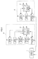
- Fig. 1 is a plan view showing the configuration when a sample analysis system 1 is viewed from the upper side.
- the sample analysis system 1 according to this embodiment is configured to include a sample recovery unit 21, a sample insertion unit 22, a sample output unit 23, three sample transport units 3, a blood cell analysis apparatus 4, a sample transport unit 5, a smear preparation apparatus 6 and a transport controller 7.
- the sample analysis system 1 of this embodiment is connected to a host computer 8 via a communication network so as to communicate therewith.
- the sample recovery unit 21, the sample insertion unit 22 and the sample transport unit 23 are configured so that a plurality of sample racks can be placed therein.
- Fig. 2 is a diagram showing the configurations of a sample container T and a sample rack L.
- Fig. 2A is a perspective view showing the appearance of a sample container T and
- Fig. 2B is a front view of a sample rack L.
- a sample container T is a tubular container made of glass or a synthetic resin having translucency and the upper end thereof is opened.
- a blood sample collected from a patient is contained and the opening of the upper end is sealed by a cap section CP.
- a bar-code label BL1 is adhered to a side surface of the sample container T.
- a bar-code showing a sample ID is printed on the bar-code label BL1.
- a bar-code label BL2 is adhered to the front side of the sample rack L.
- a bar-code showing a rack ID is printed on the bar-code label BL2.
- the sample recovery unit 21 stores sample racks L in which analysis has ended.
- the sample insertion unit 22 stores sample racks L which are inserted by an operator, and outputs the stored sample racks L to the sample output unit 23.
- the sample recovery unit 21 and the sample insertion unit 22 are connected to the transport controller 7 so as to communicate therewith.
- sample output unit 23 a rack ID of the sample rack L which is output from the sample insertion unit 22 and a sample ID of the sample container T which is associated with a holding position in the sample rack L are read.
- the sample output unit 23 outputs to the sample transport unit 3 the sample rack L, the bar-code of which has been read.
- the sample output unit 23 is connected to the transport controller 7 so as to communicate therewith, and the rack ID and the sample ID read by the sample output unit 23 are transmitted to the transport controller 7.
- the configurations of the sample insertion unit 22 and the sample output unit 23 will be described later with reference to Fig. 3 .
- the three sample transport units 3 are disposed in front of three measuring units 41, respectively.
- the neighboring two sample transport units 3 are connected to each other so as to deliver sample racks L.
- the right end of the sample transport unit 3 on the right side is connected to the sample output unit 23 so as to deliver sample racks L
- the left end of the sample transport unit 3 on the left side is connected to the sample transport unit 5 so as to deliver sample racks L.
- the three sample transport units 3 are connected to an information processing unit 42 and the transport controller 7 so as to communicate therewith.
- two transport lines L1 and L2 for transporting sample racks L are set by dividing cases into the case in which the measurement of a sample is performed in the respective corresponding measuring units 41 and the case in which the measurement is not performed. That is, when the measurement of a sample is performed by the measuring unit 41, a sample rack L is transported along the transport line L1 shown by the rear arrow. When the measurement of a sample is not performed by the measuring unit 41, a sample rack L is transported along the transport line L2 shown by the intermediate left-pointing arrow so as to skip the measuring unit 41.
- a transport line L3 for transporting sample racks L to the sample recovery unit 21 is set. That is, a sample rack L, for which measurement or preparation of a smear has ended, is transported along the transport line L3 shown by the front right-pointing arrow and is recovered by the sample recovery unit 21.
- the configuration of the sample transport unit 3 will be described later with reference to Fig. 4 .
- the blood cell analysis apparatus 4 is an optical flow cytometry type multiple blood cell analysis apparatus and includes the three measuring units 41 and the information processing apparatus 42.
- the information processing unit 42 is connected to the three measuring units 41 so as to communicate therewith, and controls the operations of the three measuring units 41.
- the information processing unit 42 is also connected to the three sample transport units 3 so as to communicate therewith.
- the three measuring units 41 measure a blood sample which is contained in a sample container T. That is, each of the three measuring units 41 takes the sample container T from the sample rack L at a predetermined position on the transport line L1 of the sample transport unit 3 disposed in front of the measuring unit. The blood sample contained in the sample container T is measured in the measuring unit 41. When the measurement in the measuring unit 41 is completed, the sample container T returns to the original holding position in the sample rack L again.
- the configuration of the measuring unit 41 will be described later with reference to Fig. 5 .
- the sample transport unit 5 is disposed in front of the smear preparation apparatus 6. As in the sample transport unit 3, transport lines L1, L2 and L3 are set in the sample transport unit 5. In addition, the sample transport unit 5 is connected to the transport controller 7 so as to communicate therewith. Further, the sample transport unit 5 is connected to the smear preparation apparatus 6, and the smear preparation apparatus 6 is driven in response to an instruction from the sample transport unit 5.
- a smear of a blood sample is prepared. That is, first, the smear preparation apparatus 6 suctions a blood sample contained in a sample container T at a predetermined position on the transport line L1 of the sample transport unit 5. Next, the suctioned blood sample is dropped onto a glass slide, thinly extended on the glass slide and then is dried. After that, a liquid dye is supplied to the glass slide to dye the blood on the glass slide and a smear is prepared.
- Whether the preparation of a smear is required is determined by the transport controller 7 on the basis of the analysis result of the three measuring units 41. As described later, the analysis result of each measuring unit 41 is transmitted to the transport controller 7 via the sample transport unit 3. When the transport controller 7 determines that the preparation of a smear is required, the sample rack L storing a target sample is transported along the transport line L1 of the sample transport unit 5 and a smear is prepared in the smear preparation apparatus 6.
- the transport controller 7 is connected to the sample recovery unit 21, the sample insertion unit 22, the sample output unit 23, the three sample transport units 3 and the sample transport unit 5 so as to communicate therewith and controls the driving of each unit.
- the transport controller 7 for example, a separate personal computer or a computer incorporated in the system is used.
- the transport controller 7 inquires of the host computer 8 for a measurement order.
- the transport controller 7 stores the measurement order in association with the rack ID, the sample ID and the holding position.
- the transport controller 7 decides whether the sample rack L which is output from the sample output unit 23 is transported to any of the three measuring units 41.
- the transport controller 7 transmits the stored measurement order to the sample transport unit 3 in front of the measuring unit 41 decided as a transport destination.
- the transport controller 7 controls each sample transport unit 3 so as to transport the sample rack L to the measuring unit 41 decided as the transport destination. Such decision of the transport destination will be described later with reference to Figs. 9 to 11 .
- the host computer 8 is connected to the communication network and can communicate with the transport controller 7. In a storage section of the host computer 8, measurement orders are stored. When the transport controller 7 requests a measurement order including a sample ID, the host computer 8 reads out the measurement order corresponding to the sample ID from the storage section and transmits the measurement order to the transport controller 7.
- Fig. 3 is a plan view showing the configuration when the sample insertion unit 22 and the sample output unit 23 are viewed from the upper side.
- Fig. 3 for the sake of convenience, the transportation of a sample rack L in the right direction along the transport line L3 is omitted in the drawing.
- a rack input mechanism 222 moves backward while engaging with the front ends of the sample rack L and thus the sample rack L is sent to the rear position (hereinafter, referred to as "position P1") of the transport passage 221.
- position P1 the position of the transport passage 221.
- a rack output mechanism 223 is driven in the left direction. In this manner, the sample rack L is output to the rear position (hereinafter, referred to as "position P2") of a transport passage 231 of the rack output unit 23 from the position P1.
- a reflective sensor 232 can detect whether the sample rack L is positioned at the position P2.
- a bar-code reading section 233 reads the rack ID of the sample rack L positioned at the position P2 and a sample ID of a sample container T in association with the holding position in the sample rack L.
- a rack input mechanism 234 the sample rack L in which the reading of the bar-codes has been completed at the position P2 is sent to a position (hereinafter, referred to as "position P3") which is moved forward by a width in the front-back direction of the sample rack L from the position 2. In this manner, even when a subsequent sample rack L is positioned at the position P1, this sample rack L can be rapidly output to the position P2.
- the sample rack L which is positioned at the position P3 is sent toward the forward position (hereinafter, referred to as "position P4") of the transport passage 231 when a rack input mechanism 235 moves forward while engaging with the rear ends of the sample rack L.
- a contact sensor 236 is disposed on the front wall of the transport passage 231.
- the sample rack L which is positioned at the position P4 is output in the left direction (to the sample transport unit 3) by a rack output mechanism 237.
- a bar-code reading section 238 reads a bar-code label BL2 of the sample rack L.
- a stepping motor (not shown) is disposed for driving the rack input mechanisms 222, 234 and 235 and the rack output mechanisms 223 and 237.
- a sensor (not shown) for detecting the position of a sample rack L on the transport passage 221 is disposed at a corresponding position.
- Fig. 4 is a plan view showing the configuration when the sample transport unit 3 is viewed from the upper side.
- the sample transport unit 3 includes a pre-analysis rack holding section 310, a rack transport section 320, a post-analysis rack holding section 330 and rack transport sections 340 and 350.
- the sample rack L is linearly sent to the left end from the right end of the rack transport section 340 along the transport line L2 by belts 341a and 341b of the rack transport section 340.
- the sample rack L is sent to the right end position of the rack transport section 340, which is shown by the broken line in the right lower portion of Fig. 4 . That is, a reflective sensor 342 shown in Fig. 4 detects that the sample rack L has been transported to the position shown by the broken line in the right lower portion of Fig. 4 . At this timing, the belt 341a is stopped. Then, when a rack pushing mechanism 343 moves backward, the sample rack L is pushed to the front end of a transport passage 311 of the pre-analysis rack holding section 310.
- optical sensors 312a and 312b including a light-emitting section and a light-receiving section detect the sample rack L on the transport passage 311, a rack input mechanism 313 moves backward while engaging with the front ends of the sample rack L and the sample rack L is sent to the back. In this manner, when the sample rack L is sent up to the right end position of the rack transport section 320, the belts 321a and 321b are driven and the sample rack L is sent in the left direction.
- the sample container sensor 322 is a contact sensor.
- a detection target sample container T which is held in the sample rack L, passes through the position under the sample container sensor 322, the contact piece of the sample container sensor 322 is bent by the sample container T and thus the presence of the sample container T is detected.
- a hand section of the measuring unit 41 which will be described later grips the sample container T and takes the sample container T from the sample rack L.
- the removed sample container T returns to the sample rack L again after used in the measurement in the measuring unit 41. While the sample container T returns to the sample rack L, the transportation of the sample rack L is on standby.
- the sample rack L is sent up to the left end position of the rack transport section 320 shown by the broken line in Fig. 4 by the belts 321a and 321b and the driving of the belts 321a and 321b is stopped. Then, the sample rack L is sent to the rear end of a transport passage 331 of the post-analysis rack holding section 330 by a rack pushing mechanism 323.
- optical sensors 332a and 332b including a light-emitting section and a light-receiving section detect the sample rack L on the transport passage 331, a rack input mechanism 333 moves forward while engaging with the rear ends of the sample rack L and the sample rack L is sent to the front.
- a partition section 360 which is in front of the post-analysis rack holding section 330 and is between the rack transport sections 340 and 350 is controlled to be opened and closed and the sample rack L is positioned in either of the rack transport sections 340 or 350.
- the sample rack L moves up to the left end position of the rack transport section 340 by the rack input mechanism 333 in a state in which the rack transport sections 340 and 350 are partitioned by the partition section 360. Then, the sample rack L is output to the sample transport unit on the downstream side by the belt 341b of the rack transport section 340.
- the upper side of the partition section 360 is dropped to be disposed at the same height as the upper side of the belt 341b of the rack transport section 340 and the sample rack L is moved up to the left end position of the rack transport section 350 by the rack input mechanism 333.
- the rack input mechanism 333 the sample rack L is moved across the rack transport section 340 from the post-analysis rack holding section 330 up to the left end position of the rack transport section 350, which is shown by the broken line in the left lower portion of the same drawing.
- the sample rack L is moved in the right direction along the transport line L3 by a belt 351 of the rack transport section 350. In this manner, the sample rack L which is transported along the transport line L3 is stored in the sample recovery unit 21.
- a stepping motor (not shown) for driving the rack pushing mechanisms 343 and 323, the rack input mechanisms 313 and 333, the belts 321a, 321b, 341a, 341b and 351 and the partition section 360 is disposed.
- a sensor (not shown) for detecting the position of a sample rack L on the transport passage is disposed at a corresponding position.
- Fig. 5 is a schematic diagram showing the configuration when the measuring unit 41 is viewed from the upper side.
- the measuring unit 41 includes a sample container transport section 411, a bar-code reading section 412, a sample suction section 413, a specimen adjustment section 414 and a detecting section 415.
- the sample container transport section 411 includes a hand section 411a and a sample container setting section 411b.
- the hand section 411a grips a sample container T positioned at the sample supply position and takes the sample container T upward from the sample rack L.
- the removed sample container T is stirred by the hand section 411a and then set in the sample container setting section 411b.
- the bar-code reading section 412 reads a bar-code label BL1 adhered to the sample container T at a bar-code reading position.
- the sample container setting section 411b is moved backward, the sample container T is positioned at the sample suction position under the sample suction section 413.
- the sample suction section 413 suctions the sample in the sample container T which is positioned at the sample suction position. After that, the sample container T returns to the original holding position in the original sample rack along the original path.
- the specimen adjustment section 414 includes a plurality of reaction chambers (not shown).
- the specimen adjustment section 414 is connected to reagent containers 414a to 414c and can supply a dye reagent of the reagent container 414a, a hemolytic agent of the reagent container 414b and a diluent of the reagent container 414c to the reaction chambers.
- the specimen adjustment section 414 is also connected to the sample suction section 413 and can supply the blood sample which is suctioned by the sample suction section 413 to the reaction chambers. Further, the specimen adjustment section 414 mixes and stirs the sample and the reagent together in the reaction chamber and prepares a specimen for measurement of the detecting section 415.
- the detecting section 415 measures a specimen which is prepared by the specimen adjustment section 414.
- the measurement data which is obtained by such measurement is analyzed by the information processing unit 42.
- Fig. 6 is a diagram showing the outline of the circuit configurations of the sample insertion unit 22 and the sample output unit 23.
- the sample insertion unit 22 includes a communication section 220, a control section 224, a sensor section 225 and a driving section 226.
- the communication section 220 performs data communication with the transport controller 7.
- the control section 224 includes a CPU 224a and a storage section 224b.
- the CPU 224a executes computer programs which are stored in the storage section 224b and controls the sections in accordance with the control section of the transport controller 7.
- the storage section 224b includes storage means such as a ROM, a RAM and a hard disk.
- the sensor section 225 includes a sensor for detecting the position of a sample rack L on the transport passage 221.
- the driving section 226 includes the above-described rack input mechanism 222, rack output mechanism 223 and a stepping motor which drives these mechanisms.
- the sample output unit 23 includes a communication section 230, the bar-code reading sections 233 and 238, a control section 240, a sensor section 241 and a driving section 242.
- the communication section 230 performs data communication with the transport controller 7.
- the control section 240 includes a CPU 240a and a storage section 240b.
- the CPU 240a executes computer programs which are stored in the storage section 240b and controls the sections in accordance with the control section of the transport controller 7.
- the storage section 240b includes storage means such as a ROM, a RAM and a hard disk.
- the rack ID of a sample rack L which is read by the bar-code reading section 233 and the sample ID of a sample container T which is associated with the holding position in the sample rack L are transmitted to the transport controller 7 via the control section 240.
- the rack ID of a sample rack L which is read by the bar-code reading section 238 is also transmitted to the transport controller 7 via the control section 240.
- the sensor section 241 includes the above-described sensors 232 and 236 and a detection signal of the sensor section 241 is output to the control section 240.
- the driving section 242 includes the above-described rack input mechanisms 234 and 235, rack output mechanism 237 and a stepping motor which drives these mechanisms.
- Fig. 7 is a diagram showing the outline of the circuit configurations of the sample transport unit 3, the measuring unit 41, the information processing unit 42 and the transport controller 7.
- the same drawing for the sake of convenience, only one sample transport unit 3 and one measuring unit 41 are shown, but the other sample transport units 3 and measuring units 41 also have the same configuration.
- the sample transport unit 3 includes communication sections 301 and 305, a control section 302, sensor sections 303 and 306 and driving sections 304 and 307.
- the driving section 307 performs the transportation of a sample rack L in a zone from when the sample rack L is forced into the pre-analysis rack holding section 310 to when the sample rack L is pushed to the post-analysis rack holding section 330. Sensors which are disposed in this zone are included in the sensor section 306 and the output of these sensors is supplied to the information processing unit 42.
- the driving section 304 performs the transportation of a sample rack L in a zone other than the transport zone of the driving section 307. Sensors which are disposed in this zone are included in the sensor section 303 and the output of these sensors is supplied to the transport controller 7.
- the communication section 301 performs data communication between the transport controller 7 and the information processing unit 42.
- the control section 302 includes a CPU 302a and a storage section 302b.
- the CPU 302a executes computer programs which are stored in the storage section 302b and controls the driving section 304 in accordance with a control section 702a of the transport controller 7.
- the storage section 302b includes storage means such as a ROM and a RAM.
- the storage section 302b stores the number of measurements which has been performed by the measuring unit 41 corresponding to the present sample transport unit 3.
- the storage section 302b is also used as a work area of the CPU 302a.
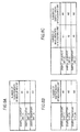
- Fig. 8A is a diagram showing the number of measurements of the measuring unit 41, which is stored in the storage section 302b of the sample transport unit 3.
- sample transport units (1) to (3) indicate the left, central and right sample transport units 3 among the three sample transport units 3.
- N1, N2 and N3 are stored respectively as the number of measurements of the corresponding measuring unit 41.
- This number of measurements is updated at the timing when the measurement of a sample is completed by the corresponding measuring unit 41. That is, when the measurement of a sample is completed by the measuring unit 41 and the measurement result of the sample is received, the information processing unit 42 issues a notice to the corresponding sample transport unit 3.
- the CPU 302a of the sample transport unit 3 adds 1 to the number of measurements which is stored in the storage section 302b.
- the sensor section 303 includes the above-described sensors 342, 332a and 332b and a detection signal of the sensor section 303 is output to the control section 302.
- the driving section 304 includes a lifting and lowering mechanism which lifts and lowers the above-described rack pushing mechanism 343, rack input mechanism 333, belts 341a, 341b and 351 and partition section 360, and a stepping motor which drives these mechanisms.
- the communication section 305 performs data communication with the information processing unit 42.
- the sensor section 306 includes the above-described sensors 312a and 312b and sample container sensor 322, and a detection signal of the sensor section 306 is transmitted to the information processing unit 42 via the communication section 305.
- the driving section 307 includes the rack pushing mechanism 323, the rack input mechanism 313, the belts 321a and 321b and a stepping motor which drives these mechanisms.
- a control section 422 of the information processing unit 42 directly controls each of the sections of the driving section 307.
- the information processing unit 42 transmits the detection signals to the control section 302 via the communication section 301 of the corresponding sample transport unit 3. Accordingly, when the CPU 702a of the transport controller 7 inquires of each sample transport unit 3 for whether there is the detection by the sensors 312a and 312b, the control section 302 of each of the sample transport unit 3 transmits whether there is the detection by the sensors 312a and 312b to the transport controller 7 on the basis of the detection signals transmitted from the information processing unit 42.
- the measuring unit 41 includes a communication section 410, the sample container transport section 411, the bar-code reading section 412, the sample suction section 413, the specimen adjustment section 414 and the detecting section 415.
- the control section 422 of the information processing unit 42 directly controls each of the sections of the measuring unit 41.
- the information processing unit 42 includes a communication section 421 and a control section 422.
- the information processing unit 42 includes an interface for performing video outputs, an interface for performing an input operation from a keyboard or the like and a read-out device such as a CD drive or a DVD drive.
- a read-out device such as a CD drive or a DVD drive.
- the communication section 421 performs data communication between the communication sections 301 and 305 of the sample transport unit 3 and the communication section 410 of the measuring unit 41.
- the control section 422 includes a CPU 422a and a storage section 422b.
- the CPU 422a executes computer programs which are stored in the storage section 422b.
- the storage section 422b includes storage means such as a ROM, a RAM and a hard disk.
- the CPU 422a analyzes the blood on the basis of the measurement result (particle data) received from the measuring unit 41 and displays the analysis result on a display section (not shown). In addition, the CPU 422a transmits the analysis result to the transport controller 7 via the sample transport unit 3.
- the transport controller 7 includes a communication section 701 and a control section 702.
- the transport controller 7 includes an interface for performing video output, an interface for performing an input operation from a keyboard or the like and a read-out device such as a CD drive or a DVD drive.
- the communication section 701 performs data communication among the sample insertion unit 22, the sample output unit 23 and the three sample transport units 3.
- the control section 702 includes a CPU 702a and a storage section 702b.
- the CPU 702a executes computer programs which are stored in the storage section 702b.
- the storage section 702b includes storage means such as a ROM, a RAM and a hard disk.
- the CPU 702a controls the driving of the sample insertion unit 22, the sample output unit 23 and the three sample transport units 3 in accordance with a computer program. In addition, the CPU 702a receives the number of measurements of each measuring unit 41 from the storage section 302b of the corresponding sample transport unit 3. The received number of measurements of each measuring unit 41 is stored for each measuring unit 41 in the storage section 702b.
- the CPU 702a controls the driving section 226 of the sample insertion unit 22 and the driving section 242 of the sample output unit 23 on the basis of detection signals from the sensor section 225 of the sample insertion unit 22 and the sensor section 241 of the sample output unit 23.
- the CPU 702a controls the driving section 304 of the sample transport unit 3 on the basis of a detection signal from the sensor section 303 of the sample transport unit 3.
- the CPU 702a determines whether the preparation of a smear is required on the basis of the sample analysis result received from the information processing unit 42 via the sample transport unit 3.
- the sample transport unit 5 (not shown) has the same configuration as the sample transport unit 3.
- the sample transport unit 5 controls a driving section of the sample transport unit 5 in accordance with an instruction of the transport controller 7, and the smear preparation apparatus 6 (not shown) is driven in response to an instruction of the sample transport unit 5.
- Figs. 9 to 12 are flowcharts showing that a sample rack L which is positioned at the position P1 of Fig. 3 is controlled to be output toward the sample transport unit 3.
- the CPU 702a of the transport controller 7 performs the following control operation.
- P2 to P4 flags which are used in the following flowcharts, show whether a sample rack L is positioned at the positions P2 to P4 of Fig. 3 , respectively. That is, the case in which values of the P2 to P4 flags are 0 show that the sample rack L is not positioned at position P2 to P4, and the case in which values of the P2 to P4 flags are 1 show that the sample rack L is positioned at the positions P2 to P4.
- the initial values of the P2 to P4 flags are 0, and the P2 to P4 flags are stored in the storage section 702b of the transport controller 7.
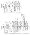
- Fig. 9A is a flowchart showing that a sample rack L which is positioned at the position P1 is controlled to be output to the position P2.
- the CPU 702a of the transport controller 7 When it is determined that a sample rack L is positioned at the position P1 (S101: YES) and when it is determined that a value of the P2 flag is 0 (S102: YES), the CPU 702a of the transport controller 7 outputs the sample rack L positioned at the position P1 to the position P2 by driving the rack output mechanism 223 (S103). At this time, the CPU 702a obtains a time when the output of the sample rack L toward the position P2 from the position P1 is started (S104) and stores it in the storage section 702b.
- the CPU 702a obtains a difference (hereinafter, referred to as "output interval") between the time obtained at this time in S104 and a time when the output of a directly previous sample rack L toward the position P2 from the position P1 is started (S105), and determines whether this output interval is greater than Tmin (S106).
- Tmin indicates an output interval when there is no sample rack L on the transport passage 231 of the sample output unit 23, sample racks L are continuously output toward the position P2 from the position P1. That is, Tmin is a value when the output interval is minimum.
- a state in which the output interval is greater than Tmin a case in which a time interval during which a sample rack L is inserted into the sample insertion unit 22 is long, or a case in which the moving of a sample rack L on the transport passage 231 of the sample output unit 23 is interrupted and a waiting time is generated for a sample rack L which is to be output toward the position P2 from the position P1 is exemplified.
- the bar-code reading section 233 reads a rack ID of the sample rack L and a sample ID of the sample container T which is associated with a holding position in the sample rack L (S109) and 1 is set to the P2 flag (S110).
- the process of S109 is completed, the process returns to S101.
- Fig. 9B is a flowchart showing that a sample rack L which is positioned at the position P2 is controlled to be sent to the position P3.
- the CPU 702a of the transport controller 7 moves a sample rack L, which is positioned at the position P2, to the position P3 by driving the rack input mechanism 234 (S203). Further, the CPU 702a sets 0 to the P2 flag (S204) and sets 1 to the P3 flag (S205). When the process of S205 is completed, the process returns to S201.
- Fig. 10 is a flowchart showing that a sample rack L which is positioned at the position P3 is controlled to be sent in the direction of the position P4.
- the CPU 702a of the transport controller 7 moves a sample rack L, which is positioned at the position P3, in the direction of the position P4 by driving the rack input mechanism 235 (S303). At this time, 0 is set to the P3 flag (S304).
- the sensor 236 detects that the front side surface of the sample rack L positioned at the position P4 has been brought into contact with the sensor 236 (S305: YES), 1 is set to the P4 flag (S306).
- the sample rack L which is sent forward is positioned at the position P4 when there are no sample racks L between the sample rack L and the position P4, and in addition, the sample rack L is positioned behind the rearmost sample rack L when there are one or more sample racks L between the sample rack L and the position P4.
- the case in which the counted number of pulses is equal to or less than Pc shows that there is a plurality of sample racks L behind the position P4 on the transport passage 231 and the rearmost sample rack L is positioned nearer to the position P3 than the predetermined position between the position P3 and the position P4.
- the case in which the counted number of pulses is greater than Pc shows that even when there is a plurality of sample racks L behind the position P4 on the transport passage 231, the rearmost sample rack L is positioned nearer to the position P4 than the predetermined position between the position P3 and the position P4. That is, when it is determined whether the counted number of pulses is equal to or less than Pc, the extent of the number of sample racks L which are arranged on the transport passage 231 is found.
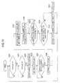
- Fig. 11 is a flowchart showing that a sample rack L which is positioned at the position P4 is controlled to be output toward the sample transport unit 3.
- the CPU 702a of the transport controller 7 determines whether an output interval flag is 0 (S402). When it is determined that the output interval flag is 0 (S402: YES), the CPU 702a determines whether the fullness flag is 0 (S403).
- the CPU 702a obtains the measuring unit 41 having the minimum number of measurements on the basis of the numbers of measurements which are stored in the memory 702b shown in Fig. 7 (S404). Next, the CPU 702a determines whether the measuring unit 41 having the minimum number of measurements, which is obtained in S404, can accept a sample rack L (S405). In this embodiment, when there are no sample racks L in the pre-analysis rack holding section 310 of the sample transport unit 3 corresponding to the measuring unit 41, it is determined that this measuring unit 41 can accept a sample rack L. In addition, as described above, such confirmation is carried out when the CPU 702a inquires of each sample transport unit 3 for whether there is the detection by the sensors 312a and 312b.
- the process stands by until it is determined that the measuring unit 41 can accept a sample rack L.
- the CPU 702a decides this measuring unit 41 as a transport destination (S406).
- the measuring unit 41 on the downstream side (left side) among the measuring units 41 is decided as a transport destination.
- the CPU 702a confirms an acceptance state of a sample rack L for each measuring unit 41 (S407). When it is determined that all the measuring units 41 cannot accept a sample rack L (S408 : NO), the process returns to S407. When it is determined that any of the measuring units 41 can accept a sample rack L (S408: YES), the CPU 702a decides as a transport destination the measuring unit 41 which is confirmed as being capable of accepting a sample rack L in S407. (S409). In addition, when the number of the measuring units 41 which can accept a sample rack L is more than one, the measuring unit 41 on the downstream side (left side) among the measuring units 41 is decided as a transport destination.
- the CPU 702a transports a sample rack L to the measuring unit 41 which is determined as a transport destination in S406 or S409 (S410). That is, first, a sample rack L which is positioned at the position P4 is output in the left direction from the sample output unit 23 by the rack output mechanism 237. In addition, in order to perform the measurement by the measuring unit 41 which is determined as a transport destination in S406 or S409, the sample rack L is transported to the pre-analysis rack holding section 310 of the sample transport unit 3 corresponding to this measuring unit 41.
- the sample racks L which are measurement targets are determined not to be crowded, and a sample rack L which is output from the sample output unit 23 is transported to the measuring unit 41 having a low measurement load, that is, to the measuring unit 41 having the minimum number of measurements.
- the measurement loads on the measuring units 41 can be equalized. Accordingly, since components and the like of the measuring units 41 are consumed at the same degree, maintenance of the measuring units 41 can be performed around the same time, so the workload for maintenance can be reduced.
- the sample racks L which are measurement targets are determined to be crowded, and a sample rack L which is output from the sample output unit 23 is transported to the measuring unit 41 which is determined to be capable of accepting a sample rack L. Accordingly, even when the sample analysis system 1 receives a number of sample racks L, the sample measurement process is conducted smoothly.
- the measuring unit which transports a sample rack L is decided on the basis of the output interval flag and the fullness flag. However, in this embodiment, statistics on a crowded state of sample racks L are further considered.
- Fig. 12 is a flowchart showing that a sample rack L which is positioned at the position P4 is controlled to be output toward the sample transport unit 3.
- S421 and S422 are added to the flowchart of Fig. 11 .
- the added processes S421 and S422 will be described only.
- the CPU 702a of the transport controller 7 obtains current time and date (S421). Next, the CPU 702a determines whether the current time and date which are obtained in S421 are in a time slot in which sample racks L are not crowded on the basis of statistics on the crowded state (S422). When it is determined that the current time and date are in a time slot in which sample racks are not crowded (S422: YES), the process proceeds to S404, and when it is determined that the current time and date are in a time slot in which sample racks are crowded (S422: NO), the process proceeds to S407.
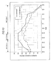
- Fig. 13 is a diagram showing statistics on the crowded state of sample racks L.
- the horizontal axis indicates a time
- the vertical axis indicates the number of measurements per hour which is performed by the three measuring units 41.
- the statistics of Monday and Wednesday are shown.
- the transport controller 7 obtains the number of measurements of each of the three measuring units 41 for every 30 minutes in the use time range (in Fig. 13 , 19:00 to 5:00) of the sample analysis system 1, and thus calculates the number of measurements per hour.
- the number of measurements per hour is stored in the storage section 702b of the transport controller 7.
- the maximum value (hereinafter, referred to as maximum number of measurements") of the number of measurements per hour which is performed by the three measuring units 41 is 300.
- the transport controller 7 stores the transition of the number of measurements per hour in the storage section 702b for every day of week and equalizes the transition of the every day of week stored over a predetermined number of dates for every day of week. In this manner, the transport controller 7 obtains the statistics on the crowded state as shown in Fig. 13 .
- the number of measurements is smaller than the maximum number of measurements per hour. Accordingly, it is found that the three measuring units 41 are not in a state to always perform the measurement (the state in which sample racks L are crowded) in the sections A and C. On the other hand, between 21:30 to 23:00 (section B in Fig. 13 ), the number of measurements per hour is the maximum number of measurements. Accordingly, it is found that the tree measuring units 41 are in a state to always perform the measurement (the state in which sample racks L are crowded) in the section B.
- the time slot (section A in Fig. 13 ) in which the number of measurements per hour reaches the maximum number of measurements is also a time slot in which the three measuring units 41 can be in a state to always perform the measurement (the state in which sample racks L are crowded).
- the reason for including the section A as well as the section B as a time slot in which sample racks L can be easily crowded on Monday is as follows.
- the three measuring units 41 are not in a state to always perform the measurement in the section A, the three measuring units 41 have a very high possibility to be in a state to always perform the measurement when the current time enters the section B. Accordingly, in the section A as a time slot in which sample racks L are crowded, when the measuring unit 41 as a transport destination is decided as shown in S407 to S409 of Fig. 12 , the measurement can be more smoothly performed when the current time enters the section B.
- S422 it is determined whether the current day of week and the current time slot are related to the time slot in which sample racks L are not crowded as described in Fig. 13 .
- the determination result is YES in S422 in the case in which the current time is included in the section A or B.
- the determination result is NO in S422 in the case in which the current time is included in the section C.
- the determination result is YES in S422 regardless of the section including the current time.
- the sample rack L is transported to the measuring unit 41 which can accept the sample rack L regardless of the number of measurements. Accordingly, a more smooth and efficient transport operation of the sample rack L can be realized.
- blood is exemplified as a measurement target.
- urine also can be a measurement target. That is, the present invention can also be applied to a sample processing apparatus which examines urine, and further, can be applied to a clinical sample examination apparatus which examines other clinical samples.
- sample racks are sorted into the three measuring units 41 of the blood cell analysis apparatus 4.
- the present invention is not limited thereto.
- a plurality of the smear preparation apparatuses 6 may be connected to sort sample racks into these smear preparation apparatuses 6.
- a sample rack L is transported to the measuring unit 41 having the minimum number of measurements.
- a sample rack L may be transported to the measuring unit 41 having the smaller number of measurements than any other measuring units 41.
- a sample rack L is transported to the measuring unit 41 having the minimum number of measurements.
- a sample rack L may be transported to the measuring unit 41 having the minimum number of sample racks L transported to the measuring unit 41.
- Fig. 8B is a diagram showing the number of sample racks L which are transported to the measuring unit 41. This number is stored in the storage section 302b of each of the sample transport units 3 and the storage section 702b of the transport controller 7. In addition, in this case, a sample rack L may be transported to the measuring unit 41 having the smaller number of sample racks L transported to the measuring unit 41 than any other measuring units 41.
- the number of measurements of the measuring unit 41 and the number of sample racks L transported to the measuring unit 41 may be stored.
- a sample rack L is transported to the measuring unit 41 having a small number of measurements of the measuring unit 41, and when the measuring units 41 have the same number of measurements, a sample rack L may be transported to the measuring unit 41 having a small number of sample racks L transported to the measuring unit 41.
- a sample rack L is transported to the measuring unit 41 having a small number of sample racks L transported to the measuring unit 41, and when the measuring units 41 have the same number of sample racks L transported to the measuring unit 41, a sample rack L may be transported to the measuring unit 41 having a small number of measurements of the measuring unit 41. Otherwise, a weighting ⁇ by which the number of measurements of the measuring unit 41 is multiplied and a weighting ⁇ by which the number of sample racks L transported to the measuring unit 41 is multiplied will be used. Accordingly, in the measuring units (1) to (3), the measuring unit 41 having the minimum value among ( ⁇ N1+ ⁇ M1), ( ⁇ N2+ ⁇ M2) and ( ⁇ N3+ ⁇ M3) may be decided as a transport destination.
- the measuring unit 41 which is a transport destination is decided on the basis of the output interval flag and the fullness flag.
- a sensor may be disposed in the sample insertion unit 22 to decide the measuring unit 41 which is a transport destination on the basis of the time interval of a sample rack L which is inserted into the sample insertion unit 22. That is, when the time interval of a sample rack L which is inserted into the sample insertion unit 22 is greater than a predetermined value, the three measuring units 41 may be determined to be in a state in which there is no need to always perform the measurement, that is, in a state in which sample racks L are not crowded, and the processes of S404 to S406 may be performed.
- the three measuring units 41 may be determined to be in a state in which it is necessary to always perform the measurement, that is, in a state in which sample racks L are crowded, and the processes S407 to S409 may be performed.
- how much the sample rack L is interrupted behind the position P4 on the transport passage 231 of the sample output unit 23 is determined by the number of pulses which are applied to the stepping motor of the rack input mechanism 235.
- a sensor may be disposed in the sample output unit 23 to detect the number of sample racks L which are on the transport passage 231 to thereby determine how much the sample rack L is interrupted.
- an output interval of a sample rack L is used as an output interval.
- an output interval of a sample rack L caused by the rack output mechanism 237 of the sample output unit 23, may be used.
- a reading interval of a bar-code label BL2 of a sample rack L caused by the bar-code reading section 233 or 238, also may be used.
- the sample rack L is transported to the measuring unit 41 on the downstream side.
- the sample rack L may be transported to the measuring unit 41 which can accept the sample rack L as rapidly as possible.
- a sample rack L can be accepted more rapidly.
- the measuring unit 41 in which the suction of all the sample containers T held in a sample rack L is most rapidly completed by the sample suction section 413 can accept the sample rack L more rapidly. Whether the suction of all the sample containers T is most rapidly completed is judged by, for example, the number of sample containers T yet to be measured.
- the measuring unit 41 in which the uptake of all the sample containers T held in the sample rack L is most rapidly completed by the hand section 411a of the measuring unit 41 can accept the sample rack L more rapidly. At this time, the sample rack L may be transported to the measuring unit 41 which can accept the sample rack L more rapidly than any other measuring units 41.
- the section B in which the number of processed samples per hour is maximum and the section A in which the number of processed samples reaches the section B are a time slot in which sample racks L are crowded.
- the section B and a predetermined duration before and after the section B may be a time slot in which sample racks L are crowded.
- sections between these sections also may be a time slot in which sample racks L are crowded.
- an operator may set a time slot in which sample racks L are crowded.
- the measuring unit 41 mixes a sample which is contained in a sample container T and reagents which are contained in the reagent containers 441 to 443 during the measurement. Accordingly, the number of measurements of the measuring unit 41 and the amount of reagents consumed by the measuring unit 41 have a proportional relationship. Accordingly, determining the measurement load on the measuring unit 41 by the number of measurements of the measuring unit 41 and determining measurement load on the measuring unit 41 by the amount of reagents consumed by the measuring unit 41 have an equivalence relationship. Accordingly, the number of measurements of the claim 6 can be said to be substantially the same as the amount of reagents consumed, and includes other parameters having an equivalence relationship with the number of measurements and the amount of reagents consumed.
- the transport controller 7 when receiving the rack ID of a sample rack L, the sample ID of a sample container T and the holding position of the sample container T from the sample output unit 23, the transport controller 7 inquires of the host computer 8 for a measurement order.
- Measurement data corresponding to sample IDs may be stored in the storage section 702b of the transport controller 7, and when the transport controller 7 receives the above-described data from the sample output unit 23, the transport controller 7 may read out measurement data corresponding to the received sample ID from the storage section 702b and transmit it to the sample output unit 23.
- the sample recovery unit 21 is disposed on the right side of the sample insertion unit 22. However, it may be disposed on the left side of the sample transport unit 5. In this case, a sample rack L in which analysis or preparation of a smear has been completed is output to the left side of the sample transport unit 5 along the transport line L2 and recovered by the sample recovery unit 21.
- the transport controller 7 decides whether to transport a sample rack L to the measuring unit 41 having the minimum number of measurements or the measuring unit 41 capable of accepting a sample rack on the basis of the output interval flag and the fullness flag.
- the transport controller 7 may include a display section to display a reception screen for receiving the selection of whether to transport the sample rack to the measuring unit 41 having the minimum number of measurements or the measuring unit 41 capable of accepting the sample rack on the display section, and an operator may select a transport method of the sample rack L via the reception screen.
- the reception screen also may be a screen for selecting and setting one of a mode which gives priority to a reduction in the measurement load on the measuring unit and a mode which gives priority to rapidity of the measurement of the sample.
Landscapes
- Physics & Mathematics (AREA)
- Health & Medical Sciences (AREA)
- Life Sciences & Earth Sciences (AREA)
- Chemical & Material Sciences (AREA)
- Analytical Chemistry (AREA)
- Biochemistry (AREA)
- General Health & Medical Sciences (AREA)
- General Physics & Mathematics (AREA)
- Immunology (AREA)
- Pathology (AREA)
- Automatic Analysis And Handling Materials Therefor (AREA)
Abstract
Description
- The present invention relates to a sample processing apparatus having a plurality of sample processing units and a sample rack transporting method for transporting sample racks to the plurality of processing units.
- Currently, sample analysis apparatuses for processing clinical samples, such as blood or urine, are used in medical institutions, such as hospitals. Some of such sample analysis apparatuses are configured to include a plurality of measuring units and a transport apparatus for transporting sample racks to the plurality of measuring units in order to improve processing capabilities.
- In such sample analysis apparatuses, a measurement load tends to become overly concentrated on one measuring unit. When the measurement load becomes concentrated on one measurement unit, breakdowns or malfunctions easily occur in the measuring unit. Accordingly, in Japanese Laid-Open Patent Publication No.
2000-88860 2000-88860 - According to the method of Japanese Laid-Open Patent Publication No.
2000-88860 - The scope of the present invention is defined solely by the appended claims, and is not affected to any degree by the statements within this summary.
- (1) According to a first aspect of the present invention, a sample processing apparatus comprising:
- a plurality of sample processing units, each processing a sample contained in a sample container;
- a transport apparatus that transports a sample rack holding a sample container to at least any one of the plurality of sample processing units;
- a rack feeding section that receives a sample rack and feeds the received sample rack to a transport line of the transport apparatus; and
- a controller capable of instructing the transport apparatus to transport a sample rack fed by the rack feeding section to (a) a sample processing unit which can accept a subsequent sample rack more rapidly than any other sample processing unit and (b) a sample processing unit having a lower processing load than any other sample processing unit.
- (2) The samples processing apparatus according to (1),
wherein the controller configured to instruct the transport apparatus, according to a quantity of sample racks received by the rack feeding section, to transport the sample rack fed by the rack feeding section to either (a) the sample processing unit which can accept the subsequent sample rack more rapidly than any other sample processing unit or (b) the sample processing unit having the lower processing load than any other sample processing unit. - (3) The sample processing apparatus according to (1) or (2), comprising a rack set section on which a sample rack is set by a user and which transfers the set sample rack to the rack feeding section,
wherein when a reception interval at which the rack feeding section receives sample racks is not greater than a predetermined interval, the controller instructs the transport apparatus to transport the sample rack fed by the rack feeding section to (a) the sample processing unit which can accept the subsequent sample rack more rapidly than any other sample processing unit, and
when the reception interval is greater than the predetermined interval, the controller instructs the transport apparatus to transport the sample rack fed by the rack feeding section to (b) the sample processing unit having the lower processing load than any other sample processing unit. - (4) The sample processing apparatus according to (3),
wherein the rack feeding section includes a storage section that stores the received sample rack before feeding the sample rack to the transport line,
when the reception interval is greater than the predetermined interval and a number of sample racks stored in the storage section is not smaller than a predetermined number, the controller instructs the transport apparatus to transport the sample rack fed by the rack feeding section to (a) the sample processing unit which can accept the subsequent sample rack more rapidly than any other sample processing unit, and
when the reception interval is greater than the predetermined interval and the number of the sample racks stored in the storage section is smaller than the predetermined number, the controller instructs the transport apparatus to transport the sample rack fed by the rack feeding section to (b) the sample processing unit having the lower processing load than any other sample processing unit. - (5) The sample processing apparatus according to (3) or (4),
wherein the rack feeding section includes a detector that detects an identification information of the received sample rack, and
the reception interval is an interval of detecting by the detector. - (6) The sample processing apparatus according to any one of (3) to (5),
wherein when a current time is included in a time slot in which a crowded state of the sample racks set in the rack set section is severe, the controller instructs the transport apparatus to transport the sample rack fed by the rack feeding section to (a) the sample processing unit which can accept the subsequent sample rack more rapidly than any other sample processing unit, even when the reception interval is greater than the predetermined interval.
According to (6), even when it is determined that sample racks are not crowded, in a time slot in which a crowded state of sample racks has a possibility to be severe, a transporting operation can be realized more smoothly and efficiently because the sample rack is transported to the sample measuring unit which can accept a subsequent sample rack more rapidly than the other sample measuring units. - (7) The sample processing apparatus according to any one of (3) to (6),
wherein the transport line of the transport apparatus comprises at a respective sample processing unit:- a sample supply line configured to transport a sample rack to supply a sample in the sample rack to a corresponding sample processing unit; and
- a bypass line that separates from the sample supply line and configured to transport a sample rack to pass through the corresponding sample processing unit or to transfer the sample rack to the corresponding sample supply line, and
- when the reception interval is not greater than a predetermined interval, the controller instructs the transport apparatus to transport a subsequent sample rack to a sample processing unit corresponding to a sample supply line on which there is no sample rack fed by the rack feeding section.
- (8) The sample processing apparatus according to any one of (1) to (7),
wherein the controller obtains a number of times that each of the sample processing units had implemented a processing of a sample, and
the sample processing unit having the lower processing load than any other sample processing unit is a sample processing unit which had implemented a processing of a sample at the smallest number of times among the plurality of sample processing units. - (9) The sample processing apparatus according to any one of (1) to (7),
wherein the controller obtains a number of sample racks transported to each of the sample processing units, and
the sample processing unit having the lower processing load than any other sample processing unit is a sample processing unit to which the smallest number of sample racks had been transported among the plurality of sample processing units. - (10) The sample processing apparatus according to any one of (1) to (9), comprising:
- a receiving part which receives a selection of whether to set (i) a first transport method for transporting the sample rack fed by the rack feeding section to the sample processing unit which can accept the subsequent sample rack more rapidly than any other sample processing unit or (ii) a second transport method for transporting the sample rack fed by the rack feeding section to the sample processing unit having the lower processing load than any other sample processing unit,
- wherein the controller instructs the transport apparatus to transport the sample rack fed by the rack feeding section by a transport method received by the receiving part.
- (11) The sample processing apparatus according to (1),
wherein the controller configured to instruct the transport apparatus to transport the sample rack fed by the rack feeding section to(a) the sample processing unit which can accept the subsequent sample rack more rapidly than any other sample processing unit when a current time is included in a time slot in which a crowded state of sample racks set in the sample processing apparatus is severe, and to instruct the transport apparatus to transport the sample rack fed by the rack feeding section to (b) the sample processing unit having the lower processing load than any other sample processing unit when the current time is not included in the time slot.
According to (11), in a time slot in which a crowded state of sample racks is severe, the sample rack is transported to the sample measuring unit which can accept a subsequent sample rack more rapidly than any other sample measuring units. Accordingly, in a time slot in which the transport apparatus becomes busy, the sample measurement process can be smoothly conducted. In addition, in a time excluding the time slot in which a crowded state of sample racks is severe, the sample rack is transported to the sample measuring unit having a lower measurement load than any other sample measuring units. Accordingly, the measurement loads of the sample measuring units can be equalized. - (12) The sample processing apparatus according to (11),
wherein the transport line of the transport apparatus comprises at a respective sample processing unit:- a sample supply line configured to transport a sample rack to supply a sample in the sample rack to a corresponding sample processing unit; and
- a bypass line that separates from the sample supply line and configured to transport a sample rack to pass through the corresponding sample processing unit or to transfer the sample rack to the corresponding sample supply line, and
- when the current time is included in the time slot, the controller instructs the transport apparatus to transport a subsequent sample rack to a sample processing unit corresponding to a sample supply line on which there is no sample rack fed by the rack feeding section.
- (13) The sample processing apparatus according to (11) or (12),
wherein the controller obtains a number of times that each of the sample processing units had implemented a processing of a sample, and
when the current time is not included in the time slot, the controller instructs the transport apparatus to transport the sample rack fed by the rack feeding section to a sample processing unit which had implemented a processing of a sample at the smallest number of times. - (14) According to a second aspect of the present invention,
a sample rack transporting method for transporting a sample rack to at least one of a plurality of sample processing units, comprising:- receiving, by a rack feeding section, a sample rack holding a sample container;
- feeding the received sample rack, by the rack feeding section, to a transport line of a rack transport apparatus;
- transporting the fed sample rack, by the rack transport apparatus, to either (a) a sample processing unit which can accept a subsequent sample rack more rapidly than any other sample processing unit or (b) a sample processing unit having a lower processing load than any other sample processing unit, according to a quantity of sample racks received by the rack feeding section.
- (15) According to a third aspect of the present invention, a sample rack transporting method for transporting a sample rack to at least one of a plurality of sample processing units, comprising:
- receiving, by a rack feeding section, a sample rack holding a sample container;
- feeding the received sample rack, by the rack feeding section, to a transport line of a rack transport apparatus;
- transporting the fed sample rack, by the rack transport apparatus, to either (a) a sample processing unit which can accept a subsequent sample rack more rapidly than any other sample processing unit or (b) a sample processing unit having a lower processing load than any other sample processing unit, according to whether or not a current time is included in a time slot in which a crowded state of the sample racks set in the sample processing apparatus is severe.
-
-
Fig. 1 is a diagram showing the configuration of a sample analysis system according to a first embodiment; -
Figs. 2A and 2B are diagrams showing the configurations of a sample container and a sample rack; -
Fig. 3 is a plan view showing the configurations of a sample insertion unit and a sample output unit according to the first embodiment; -
Fig. 4 is a plan view showing the configuration of a sample transport unit according to the first embodiment; -
Fig. 5 is a schematic diagram showing the configuration of a measuring unit according to the first embodiment; -
Fig. 6 is a diagram showing the outline of the circuit configurations of the sample insertion unit and the sample output unit according to the first embodiment; -
Fig. 7 is a diagram showing the outline of the circuit configurations of the sample transport unit, the measuring unit, an information processing unit and a transport controller according to the first embodiment; -
Figs. 8A to 8C include a chart showing the number of measurements of the measuring unit according to the first embodiment and a chart showing the number of sample racks transported to the measuring unit, which is used in place of the number of measurements according to a modified example of the embodiment; -
Figs. 9A and 9B are flowcharts showing that a sample rack which is positioned at the rear position of the sample insertion unit according to the first embodiment is controlled to be output toward the sample transport unit; -
Fig. 10 is a flowchart showing that a sample rack which is positioned at the rear position of the sample insertion unit according to the first embodiment is controlled to be output toward the sample transport unit; -
Fig. 11 is a flowchart showing that a sample rack which is positioned at the rear position of the sample insertion unit according to the first embodiment is controlled to be output toward the sample transport unit; -
Fig. 12 is a flowchart showing that a sample rack which is positioned at the rear position of a sample insertion unit according to a second embodiment is controlled to be output toward a sample transport unit; and -
Fig. 13 is a diagram showing statistics on the crowded state of sample racks according to the second embodiment. - This embodiment is a sample analysis system for examination and analysis related to blood, to which the present invention is applied. A sample analysis system according to this embodiment includes three measuring units and one smear preparation apparatus. In the three measuring units, blood analysis is performed in parallel, and when it is necessary to prepare a smear based on the analysis result thereof, the smear preparation apparatus prepares a smear.
- Hereinafter, a sample analysis system according to a first embodiment will be described with reference to the drawings.
-
Fig. 1 is a plan view showing the configuration when asample analysis system 1 is viewed from the upper side. Thesample analysis system 1 according to this embodiment is configured to include asample recovery unit 21, asample insertion unit 22, asample output unit 23, threesample transport units 3, a bloodcell analysis apparatus 4, asample transport unit 5, asmear preparation apparatus 6 and atransport controller 7. In addition, thesample analysis system 1 of this embodiment is connected to ahost computer 8 via a communication network so as to communicate therewith. - The
sample recovery unit 21, thesample insertion unit 22 and thesample transport unit 23 are configured so that a plurality of sample racks can be placed therein. -
Fig. 2 is a diagram showing the configurations of a sample container T and a sample rack L.Fig. 2A is a perspective view showing the appearance of a sample container T andFig. 2B is a front view of a sample rack L. - Referring to
Fig. 2A , a sample container T is a tubular container made of glass or a synthetic resin having translucency and the upper end thereof is opened. In the sample container, a blood sample collected from a patient is contained and the opening of the upper end is sealed by a cap section CP. A bar-code label BL1 is adhered to a side surface of the sample container T. A bar-code showing a sample ID is printed on the bar-code label BL1. - Referring to
Fig. 2B , in a sample rack L, ten holding positions are formed so as to arrange and hold ten sample containers T in a vertical state (erect state). In addition, as shown in the drawing, a bar-code label BL2 is adhered to the front side of the sample rack L. A bar-code showing a rack ID is printed on the bar-code label BL2. - Returning to
Fig. 1 , thesample recovery unit 21 stores sample racks L in which analysis has ended. Thesample insertion unit 22 stores sample racks L which are inserted by an operator, and outputs the stored sample racks L to thesample output unit 23. In addition, thesample recovery unit 21 and thesample insertion unit 22 are connected to thetransport controller 7 so as to communicate therewith. - In the
sample output unit 23, a rack ID of the sample rack L which is output from thesample insertion unit 22 and a sample ID of the sample container T which is associated with a holding position in the sample rack L are read. Thesample output unit 23 outputs to thesample transport unit 3 the sample rack L, the bar-code of which has been read. In addition, thesample output unit 23 is connected to thetransport controller 7 so as to communicate therewith, and the rack ID and the sample ID read by thesample output unit 23 are transmitted to thetransport controller 7. The configurations of thesample insertion unit 22 and thesample output unit 23 will be described later with reference toFig. 3 . - As shown in the drawing, the three
sample transport units 3 are disposed in front of three measuringunits 41, respectively. The neighboring twosample transport units 3 are connected to each other so as to deliver sample racks L. The right end of thesample transport unit 3 on the right side is connected to thesample output unit 23 so as to deliver sample racks L, and the left end of thesample transport unit 3 on the left side is connected to thesample transport unit 5 so as to deliver sample racks L. In addition, the threesample transport units 3 are connected to aninformation processing unit 42 and thetransport controller 7 so as to communicate therewith. - As shown in the drawing, in these three
sample transport units 3, two transport lines L1 and L2 for transporting sample racks L are set by dividing cases into the case in which the measurement of a sample is performed in the respective corresponding measuringunits 41 and the case in which the measurement is not performed. That is, when the measurement of a sample is performed by the measuringunit 41, a sample rack L is transported along the transport line L1 shown by the rear arrow. When the measurement of a sample is not performed by the measuringunit 41, a sample rack L is transported along the transport line L2 shown by the intermediate left-pointing arrow so as to skip the measuringunit 41. - Further, as shown in the drawing, in the three
sample transport units 3, a transport line L3 for transporting sample racks L to thesample recovery unit 21 is set. That is, a sample rack L, for which measurement or preparation of a smear has ended, is transported along the transport line L3 shown by the front right-pointing arrow and is recovered by thesample recovery unit 21. The configuration of thesample transport unit 3 will be described later with reference toFig. 4 . - The blood
cell analysis apparatus 4 is an optical flow cytometry type multiple blood cell analysis apparatus and includes the three measuringunits 41 and theinformation processing apparatus 42. Theinformation processing unit 42 is connected to the three measuringunits 41 so as to communicate therewith, and controls the operations of the three measuringunits 41. In addition, theinformation processing unit 42 is also connected to the threesample transport units 3 so as to communicate therewith. - The three measuring
units 41 measure a blood sample which is contained in a sample container T. That is, each of the three measuringunits 41 takes the sample container T from the sample rack L at a predetermined position on the transport line L1 of thesample transport unit 3 disposed in front of the measuring unit. The blood sample contained in the sample container T is measured in the measuringunit 41. When the measurement in the measuringunit 41 is completed, the sample container T returns to the original holding position in the sample rack L again. The configuration of the measuringunit 41 will be described later with reference toFig. 5 . - The
sample transport unit 5 is disposed in front of thesmear preparation apparatus 6. As in thesample transport unit 3, transport lines L1, L2 and L3 are set in thesample transport unit 5. In addition, thesample transport unit 5 is connected to thetransport controller 7 so as to communicate therewith. Further, thesample transport unit 5 is connected to thesmear preparation apparatus 6, and thesmear preparation apparatus 6 is driven in response to an instruction from thesample transport unit 5. - In the
smear preparation apparatus 6, a smear of a blood sample is prepared. That is, first, thesmear preparation apparatus 6 suctions a blood sample contained in a sample container T at a predetermined position on the transport line L1 of thesample transport unit 5. Next, the suctioned blood sample is dropped onto a glass slide, thinly extended on the glass slide and then is dried. After that, a liquid dye is supplied to the glass slide to dye the blood on the glass slide and a smear is prepared. - Whether the preparation of a smear is required is determined by the
transport controller 7 on the basis of the analysis result of the three measuringunits 41. As described later, the analysis result of each measuringunit 41 is transmitted to thetransport controller 7 via thesample transport unit 3. When thetransport controller 7 determines that the preparation of a smear is required, the sample rack L storing a target sample is transported along the transport line L1 of thesample transport unit 5 and a smear is prepared in thesmear preparation apparatus 6. - The
transport controller 7 is connected to thesample recovery unit 21, thesample insertion unit 22, thesample output unit 23, the threesample transport units 3 and thesample transport unit 5 so as to communicate therewith and controls the driving of each unit. As thetransport controller 7, for example, a separate personal computer or a computer incorporated in the system is used. - When receiving the rack ID of a sample rack L, the sample ID of a sample container T and the holding position of the sample container T from the
sample output unit 23, thetransport controller 7 inquires of thehost computer 8 for a measurement order. When receiving the measurement order from thehost computer 8, thetransport controller 7 stores the measurement order in association with the rack ID, the sample ID and the holding position. - In addition, on the basis of a time interval during which a sample rack L is output to the
sample output unit 23 from thesample insertion unit 22, thetransport controller 7 decides whether the sample rack L which is output from thesample output unit 23 is transported to any of the three measuringunits 41. Thetransport controller 7 transmits the stored measurement order to thesample transport unit 3 in front of the measuringunit 41 decided as a transport destination. Thetransport controller 7 controls eachsample transport unit 3 so as to transport the sample rack L to the measuringunit 41 decided as the transport destination. Such decision of the transport destination will be described later with reference toFigs. 9 to 11 . - The
host computer 8 is connected to the communication network and can communicate with thetransport controller 7. In a storage section of thehost computer 8, measurement orders are stored. When thetransport controller 7 requests a measurement order including a sample ID, thehost computer 8 reads out the measurement order corresponding to the sample ID from the storage section and transmits the measurement order to thetransport controller 7. -
Fig. 3 is a plan view showing the configuration when thesample insertion unit 22 and thesample output unit 23 are viewed from the upper side. InFig. 3 , for the sake of convenience, the transportation of a sample rack L in the right direction along the transport line L3 is omitted in the drawing. - When a sample rack L is inserted onto a
transport passage 221 of thesample insertion unit 22, arack input mechanism 222 moves backward while engaging with the front ends of the sample rack L and thus the sample rack L is sent to the rear position (hereinafter, referred to as "position P1") of thetransport passage 221. When the sample rack L1 is positioned at the position P1, arack output mechanism 223 is driven in the left direction. In this manner, the sample rack L is output to the rear position (hereinafter, referred to as "position P2") of atransport passage 231 of therack output unit 23 from the position P1. Areflective sensor 232 can detect whether the sample rack L is positioned at the position P2. - A bar-
code reading section 233 reads the rack ID of the sample rack L positioned at the position P2 and a sample ID of a sample container T in association with the holding position in the sample rack L. By arack input mechanism 234, the sample rack L in which the reading of the bar-codes has been completed at the position P2 is sent to a position (hereinafter, referred to as "position P3") which is moved forward by a width in the front-back direction of the sample rack L from theposition 2. In this manner, even when a subsequent sample rack L is positioned at the position P1, this sample rack L can be rapidly output to the position P2. - Next, the sample rack L which is positioned at the position P3 is sent toward the forward position (hereinafter, referred to as "position P4") of the
transport passage 231 when arack input mechanism 235 moves forward while engaging with the rear ends of the sample rack L. Here, acontact sensor 236 is disposed on the front wall of thetransport passage 231. When there is a plurality of sample racks L in the rear of the position P4 already, the sample rack L which is sent forward by therack input mechanism 235 is pressed against the rearmost sample rack L among the plurality of sample racks L. Accordingly, the front side surface of the sample rack L which is positioned at the position P4 is pressed against thesensor 236 and it is determined that the delivery of therack input mechanism 235 is completed. Therack input mechanism 235 which has completed the delivery is returned to the rear of the position at which the delivery has been completed. - The sample rack L which is positioned at the position P4 is output in the left direction (to the sample transport unit 3) by a
rack output mechanism 237. At this time, a bar-code reading section 238 reads a bar-code label BL2 of the sample rack L. - In the
sample insertion unit 22 and thesample output unit 23, a stepping motor (not shown) is disposed for driving therack input mechanisms rack output mechanisms sample insertion unit 22, a sensor (not shown) for detecting the position of a sample rack L on thetransport passage 221 is disposed at a corresponding position. -
Fig. 4 is a plan view showing the configuration when thesample transport unit 3 is viewed from the upper side. Thesample transport unit 3 includes a pre-analysisrack holding section 310, arack transport section 320, a post-analysisrack holding section 330 andrack transport sections - When the measurement of a sample rack L is not performed, the sample rack L is linearly sent to the left end from the right end of the
rack transport section 340 along the transport line L2 bybelts rack transport section 340. - When the measurement of a sample rack L is performed, the sample rack L is sent to the right end position of the
rack transport section 340, which is shown by the broken line in the right lower portion ofFig. 4 . That is, areflective sensor 342 shown inFig. 4 detects that the sample rack L has been transported to the position shown by the broken line in the right lower portion ofFig. 4 . At this timing, thebelt 341a is stopped. Then, when arack pushing mechanism 343 moves backward, the sample rack L is pushed to the front end of atransport passage 311 of the pre-analysisrack holding section 310. Whenoptical sensors transport passage 311, arack input mechanism 313 moves backward while engaging with the front ends of the sample rack L and the sample rack L is sent to the back. In this manner, when the sample rack L is sent up to the right end position of therack transport section 320, thebelts - After that, the sample rack L arrives at the position of a
sample container sensor 322. Thesample container sensor 322 is a contact sensor. When a detection target sample container T, which is held in the sample rack L, passes through the position under thesample container sensor 322, the contact piece of thesample container sensor 322 is bent by the sample container T and thus the presence of the sample container T is detected. - At a sample supply position positioned on the left side of the position, at which the sample container T has been detected by the
sample container sensor 322, by a distance corresponding to two sample containers, a hand section of the measuringunit 41 which will be described later grips the sample container T and takes the sample container T from the sample rack L. The removed sample container T returns to the sample rack L again after used in the measurement in the measuringunit 41. While the sample container T returns to the sample rack L, the transportation of the sample rack L is on standby. - In this manner, when the measurement of the samples in all of the sample containers T held in the sample rack L is completed, the sample rack L is sent up to the left end position of the
rack transport section 320 shown by the broken line inFig. 4 by thebelts belts transport passage 331 of the post-analysisrack holding section 330 by arack pushing mechanism 323. Whenoptical sensors transport passage 331, arack input mechanism 333 moves forward while engaging with the rear ends of the sample rack L and the sample rack L is sent to the front. At this time, apartition section 360 which is in front of the post-analysisrack holding section 330 and is between therack transport sections rack transport sections - As a result of the measurement by the measuring
unit 41, when it is determined that thesmear preparation apparatus 6 on the downstream side needs to prepare smears related to sample containers T which are held in the sample rack L, the sample rack L moves up to the left end position of therack transport section 340 by therack input mechanism 333 in a state in which therack transport sections partition section 360. Then, the sample rack L is output to the sample transport unit on the downstream side by thebelt 341b of therack transport section 340. - On the other hand, as a result of the measurement by the measuring
unit 41, when it is determined that thesmear preparation apparatus 6 on the downstream side does not need to prepare smears related to the sample containers T which are held in the sample rack L, the upper side of thepartition section 360 is dropped to be disposed at the same height as the upper side of thebelt 341b of therack transport section 340 and the sample rack L is moved up to the left end position of therack transport section 350 by therack input mechanism 333. In this manner, by therack input mechanism 333, the sample rack L is moved across therack transport section 340 from the post-analysisrack holding section 330 up to the left end position of therack transport section 350, which is shown by the broken line in the left lower portion of the same drawing. Then, the sample rack L is moved in the right direction along the transport line L3 by abelt 351 of therack transport section 350. In this manner, the sample rack L which is transported along the transport line L3 is stored in thesample recovery unit 21. - In the
sample transport unit 3, a stepping motor (not shown) for driving therack pushing mechanisms rack input mechanisms belts partition section 360 is disposed. In addition, in thesample transport unit 3, in addition to thesensors sample container sensor 322, a sensor (not shown) for detecting the position of a sample rack L on the transport passage is disposed at a corresponding position. -
Fig. 5 is a schematic diagram showing the configuration when the measuringunit 41 is viewed from the upper side. The measuringunit 41 includes a samplecontainer transport section 411, a bar-code reading section 412, asample suction section 413, aspecimen adjustment section 414 and a detectingsection 415. - The sample
container transport section 411 includes ahand section 411a and a samplecontainer setting section 411b. Thehand section 411a grips a sample container T positioned at the sample supply position and takes the sample container T upward from the sample rack L. The removed sample container T is stirred by thehand section 411a and then set in the samplecontainer setting section 411b. Regarding the sample container T which is set in the samplecontainer setting section 411b, the bar-code reading section 412 reads a bar-code label BL1 adhered to the sample container T at a bar-code reading position. Then, when the samplecontainer setting section 411b is moved backward, the sample container T is positioned at the sample suction position under thesample suction section 413. Thesample suction section 413 suctions the sample in the sample container T which is positioned at the sample suction position. After that, the sample container T returns to the original holding position in the original sample rack along the original path. - The
specimen adjustment section 414 includes a plurality of reaction chambers (not shown). Thespecimen adjustment section 414 is connected toreagent containers 414a to 414c and can supply a dye reagent of thereagent container 414a, a hemolytic agent of thereagent container 414b and a diluent of thereagent container 414c to the reaction chambers. In addition, thespecimen adjustment section 414 is also connected to thesample suction section 413 and can supply the blood sample which is suctioned by thesample suction section 413 to the reaction chambers. Further, thespecimen adjustment section 414 mixes and stirs the sample and the reagent together in the reaction chamber and prepares a specimen for measurement of the detectingsection 415. - The detecting
section 415 measures a specimen which is prepared by thespecimen adjustment section 414. The measurement data which is obtained by such measurement is analyzed by theinformation processing unit 42. -
Fig. 6 is a diagram showing the outline of the circuit configurations of thesample insertion unit 22 and thesample output unit 23. - The
sample insertion unit 22 includes acommunication section 220, acontrol section 224, asensor section 225 and adriving section 226. Thecommunication section 220 performs data communication with thetransport controller 7. Thecontrol section 224 includes aCPU 224a and astorage section 224b. TheCPU 224a executes computer programs which are stored in thestorage section 224b and controls the sections in accordance with the control section of thetransport controller 7. Thestorage section 224b includes storage means such as a ROM, a RAM and a hard disk. - The
sensor section 225 includes a sensor for detecting the position of a sample rack L on thetransport passage 221. Thedriving section 226 includes the above-describedrack input mechanism 222,rack output mechanism 223 and a stepping motor which drives these mechanisms. - The
sample output unit 23 includes acommunication section 230, the bar-code reading sections control section 240, asensor section 241 and adriving section 242. Thecommunication section 230 performs data communication with thetransport controller 7. Thecontrol section 240 includes aCPU 240a and astorage section 240b. TheCPU 240a executes computer programs which are stored in thestorage section 240b and controls the sections in accordance with the control section of thetransport controller 7. Thestorage section 240b includes storage means such as a ROM, a RAM and a hard disk. - The rack ID of a sample rack L which is read by the bar-
code reading section 233 and the sample ID of a sample container T which is associated with the holding position in the sample rack L are transmitted to thetransport controller 7 via thecontrol section 240. In addition, the rack ID of a sample rack L which is read by the bar-code reading section 238 is also transmitted to thetransport controller 7 via thecontrol section 240. - The
sensor section 241 includes the above-describedsensors sensor section 241 is output to thecontrol section 240. Thedriving section 242 includes the above-describedrack input mechanisms rack output mechanism 237 and a stepping motor which drives these mechanisms. -
Fig. 7 is a diagram showing the outline of the circuit configurations of thesample transport unit 3, the measuringunit 41, theinformation processing unit 42 and thetransport controller 7. In the same drawing, for the sake of convenience, only onesample transport unit 3 and one measuringunit 41 are shown, but the othersample transport units 3 and measuringunits 41 also have the same configuration. - The
sample transport unit 3 includescommunication sections control section 302,sensor sections sections - The
driving section 307 performs the transportation of a sample rack L in a zone from when the sample rack L is forced into the pre-analysisrack holding section 310 to when the sample rack L is pushed to the post-analysisrack holding section 330. Sensors which are disposed in this zone are included in thesensor section 306 and the output of these sensors is supplied to theinformation processing unit 42. In addition, thedriving section 304 performs the transportation of a sample rack L in a zone other than the transport zone of thedriving section 307. Sensors which are disposed in this zone are included in thesensor section 303 and the output of these sensors is supplied to thetransport controller 7. - The
communication section 301 performs data communication between thetransport controller 7 and theinformation processing unit 42. Thecontrol section 302 includes aCPU 302a and astorage section 302b. TheCPU 302a executes computer programs which are stored in thestorage section 302b and controls thedriving section 304 in accordance with acontrol section 702a of thetransport controller 7. Thestorage section 302b includes storage means such as a ROM and a RAM. Thestorage section 302b stores the number of measurements which has been performed by the measuringunit 41 corresponding to the presentsample transport unit 3. In addition, thestorage section 302b is also used as a work area of theCPU 302a. - Here, the number of measurements which is stored in the
storage section 302b will be described. -
Fig. 8A is a diagram showing the number of measurements of the measuringunit 41, which is stored in thestorage section 302b of thesample transport unit 3. InFig. 8A , sample transport units (1) to (3) indicate the left, central and rightsample transport units 3 among the threesample transport units 3. - As shown in the drawing, in the
storage sections 302b of the sample transport units (1) to (3), N1, N2 and N3 are stored respectively as the number of measurements of the corresponding measuringunit 41. This number of measurements is updated at the timing when the measurement of a sample is completed by the corresponding measuringunit 41. That is, when the measurement of a sample is completed by the measuringunit 41 and the measurement result of the sample is received, theinformation processing unit 42 issues a notice to the correspondingsample transport unit 3. When receiving the notice, theCPU 302a of thesample transport unit 3 adds 1 to the number of measurements which is stored in thestorage section 302b. - Returning to
Fig. 7 , thesensor section 303 includes the above-describedsensors sensor section 303 is output to thecontrol section 302. Thedriving section 304 includes a lifting and lowering mechanism which lifts and lowers the above-describedrack pushing mechanism 343,rack input mechanism 333,belts partition section 360, and a stepping motor which drives these mechanisms. - The
communication section 305 performs data communication with theinformation processing unit 42. Thesensor section 306 includes the above-describedsensors sample container sensor 322, and a detection signal of thesensor section 306 is transmitted to theinformation processing unit 42 via thecommunication section 305. Thedriving section 307 includes therack pushing mechanism 323, therack input mechanism 313, thebelts control section 422 of theinformation processing unit 42 directly controls each of the sections of thedriving section 307. - When detection signals of the
sensors sensor section 306 are transmitted to theinformation processing unit 42, theinformation processing unit 42 transmits the detection signals to thecontrol section 302 via thecommunication section 301 of the correspondingsample transport unit 3. Accordingly, when theCPU 702a of thetransport controller 7 inquires of eachsample transport unit 3 for whether there is the detection by thesensors control section 302 of each of thesample transport unit 3 transmits whether there is the detection by thesensors transport controller 7 on the basis of the detection signals transmitted from theinformation processing unit 42. - The measuring
unit 41 includes acommunication section 410, the samplecontainer transport section 411, the bar-code reading section 412, thesample suction section 413, thespecimen adjustment section 414 and the detectingsection 415. Thecontrol section 422 of theinformation processing unit 42 directly controls each of the sections of the measuringunit 41. - The
information processing unit 42 includes acommunication section 421 and acontrol section 422. In addition, theinformation processing unit 42 includes an interface for performing video outputs, an interface for performing an input operation from a keyboard or the like and a read-out device such as a CD drive or a DVD drive. However, here, the description thereof will be omitted. - The
communication section 421 performs data communication between thecommunication sections sample transport unit 3 and thecommunication section 410 of the measuringunit 41. Thecontrol section 422 includes aCPU 422a and a storage section 422b. TheCPU 422a executes computer programs which are stored in the storage section 422b. The storage section 422b includes storage means such as a ROM, a RAM and a hard disk. - The
CPU 422a analyzes the blood on the basis of the measurement result (particle data) received from the measuringunit 41 and displays the analysis result on a display section (not shown). In addition, theCPU 422a transmits the analysis result to thetransport controller 7 via thesample transport unit 3. - The
transport controller 7 includes acommunication section 701 and acontrol section 702. In addition, thetransport controller 7 includes an interface for performing video output, an interface for performing an input operation from a keyboard or the like and a read-out device such as a CD drive or a DVD drive. - The
communication section 701 performs data communication among thesample insertion unit 22, thesample output unit 23 and the threesample transport units 3. Thecontrol section 702 includes aCPU 702a and astorage section 702b. TheCPU 702a executes computer programs which are stored in thestorage section 702b. Thestorage section 702b includes storage means such as a ROM, a RAM and a hard disk. - The
CPU 702a controls the driving of thesample insertion unit 22, thesample output unit 23 and the threesample transport units 3 in accordance with a computer program. In addition, theCPU 702a receives the number of measurements of each measuringunit 41 from thestorage section 302b of the correspondingsample transport unit 3. The received number of measurements of each measuringunit 41 is stored for each measuringunit 41 in thestorage section 702b. - In addition, the
CPU 702a controls thedriving section 226 of thesample insertion unit 22 and thedriving section 242 of thesample output unit 23 on the basis of detection signals from thesensor section 225 of thesample insertion unit 22 and thesensor section 241 of thesample output unit 23. TheCPU 702a controls thedriving section 304 of thesample transport unit 3 on the basis of a detection signal from thesensor section 303 of thesample transport unit 3. TheCPU 702a determines whether the preparation of a smear is required on the basis of the sample analysis result received from theinformation processing unit 42 via thesample transport unit 3. - The sample transport unit 5 (not shown) has the same configuration as the
sample transport unit 3. Thesample transport unit 5 controls a driving section of thesample transport unit 5 in accordance with an instruction of thetransport controller 7, and the smear preparation apparatus 6 (not shown) is driven in response to an instruction of thesample transport unit 5. -
Figs. 9 to 12 are flowcharts showing that a sample rack L which is positioned at the position P1 ofFig. 3 is controlled to be output toward thesample transport unit 3. - The
CPU 702a of thetransport controller 7 performs the following control operation. In addition, P2 to P4 flags, which are used in the following flowcharts, show whether a sample rack L is positioned at the positions P2 to P4 ofFig. 3 , respectively. That is, the case in which values of the P2 to P4 flags are 0 show that the sample rack L is not positioned at position P2 to P4, and the case in which values of the P2 to P4 flags are 1 show that the sample rack L is positioned at the positions P2 to P4. The initial values of the P2 to P4 flags are 0, and the P2 to P4 flags are stored in thestorage section 702b of thetransport controller 7. -
Fig. 9A is a flowchart showing that a sample rack L which is positioned at the position P1 is controlled to be output to the position P2. - When it is determined that a sample rack L is positioned at the position P1 (S101: YES) and when it is determined that a value of the P2 flag is 0 (S102: YES), the
CPU 702a of thetransport controller 7 outputs the sample rack L positioned at the position P1 to the position P2 by driving the rack output mechanism 223 (S103). At this time, theCPU 702a obtains a time when the output of the sample rack L toward the position P2 from the position P1 is started (S104) and stores it in thestorage section 702b. - Next, the
CPU 702a obtains a difference (hereinafter, referred to as "output interval") between the time obtained at this time in S104 and a time when the output of a directly previous sample rack L toward the position P2 from the position P1 is started (S105), and determines whether this output interval is greater than Tmin (S106). Here, Tmin indicates an output interval when there is no sample rack L on thetransport passage 231 of thesample output unit 23, sample racks L are continuously output toward the position P2 from the position P1. That is, Tmin is a value when the output interval is minimum. - When it is determined that the output interval is greater than Tmin (S106: YES), 0 is set to the output interval flag (S107). When it is determined that the output interval is not greater than Tmin, that is, when it is determined that the output interval is equal to Tmin (S106: NO), 1 is set to the output interval flag. The output interval flag is stored in the
storage section 702b of thetransport controller 7 and the initial value thereof is 0. When a directly previous sample rack L does not exist, that is, when the sample rack L output at this time is a sample rack L which is initially output, the determination result is YES in S106. - Here, as a state in which the output interval is greater than Tmin, a case in which a time interval during which a sample rack L is inserted into the
sample insertion unit 22 is long, or a case in which the moving of a sample rack L on thetransport passage 231 of thesample output unit 23 is interrupted and a waiting time is generated for a sample rack L which is to be output toward the position P2 from the position P1 is exemplified. - Next, at the position P2, the bar-
code reading section 233 reads a rack ID of the sample rack L and a sample ID of the sample container T which is associated with a holding position in the sample rack L (S109) and 1 is set to the P2 flag (S110). When the process of S109 is completed, the process returns to S101. -
Fig. 9B is a flowchart showing that a sample rack L which is positioned at the position P2 is controlled to be sent to the position P3. - When it is determined that a value of the P2 flag is 1 (S201: YES) and when it is determined that a value of the P3 flag is 0 (S202: YES), the
CPU 702a of thetransport controller 7 moves a sample rack L, which is positioned at the position P2, to the position P3 by driving the rack input mechanism 234 (S203). Further, theCPU 702a sets 0 to the P2 flag (S204) and sets 1 to the P3 flag (S205). When the process of S205 is completed, the process returns to S201. -
Fig. 10 is a flowchart showing that a sample rack L which is positioned at the position P3 is controlled to be sent in the direction of the position P4. - When it is determined that the P3 flag is 1 (S301: YES) and when it is determined that a value of the P4 flag is 0 (S302: YES), the
CPU 702a of thetransport controller 7 moves a sample rack L, which is positioned at the position P3, in the direction of the position P4 by driving the rack input mechanism 235 (S303). At this time, 0 is set to the P3 flag (S304). - In the case in which by moving the sample rack L in the direction of the position P4, as described above, the
sensor 236 detects that the front side surface of the sample rack L positioned at the position P4 has been brought into contact with the sensor 236 (S305: YES), 1 is set to the P4 flag (S306). In this manner, the sample rack L which is sent forward is positioned at the position P4 when there are no sample racks L between the sample rack L and the position P4, and in addition, the sample rack L is positioned behind the rearmost sample rack L when there are one or more sample racks L between the sample rack L and the position P4. - Next, the moving of the
rack input mechanism 235, which has completed the delivery of the sample rack L, backward is started so as to return to the position P3 (S307). At this time, the number of pulses which are applied to the stepping motor driving therack input mechanism 235 is counted (S308). When it is determined that the moving of therack input mechanism 235 to the position P3 has been completed (S309: YES), it is determined whether the counted number of pulses is equal to or less than Pc (S310). Pc is set to the number of pulses which are counted when the rack input mechanism returns to P3 from a predetermined position between the position P3 and the position P4. - Here, the case in which the counted number of pulses is equal to or less than Pc (S310: YES) shows that there is a plurality of sample racks L behind the position P4 on the
transport passage 231 and the rearmost sample rack L is positioned nearer to the position P3 than the predetermined position between the position P3 and the position P4. On the other hand, the case in which the counted number of pulses is greater than Pc (S310: NO) shows that even when there is a plurality of sample racks L behind the position P4 on thetransport passage 231, the rearmost sample rack L is positioned nearer to the position P4 than the predetermined position between the position P3 and the position P4. That is, when it is determined whether the counted number of pulses is equal to or less than Pc, the extent of the number of sample racks L which are arranged on thetransport passage 231 is found. - When it is determined that the counted number of pulses is equal to or less than Pc (P310: YES), 1 is set to a fullness flag (S311) to show that the number of sample racks L which are arranged behind the position P4 is equal to or greater than a predetermined number. On the other hand, when it is determined that the counted number of pulses is greater than Pc (P310: NO), 0 is set to the fullness flag (S312) to show that the number of sample racks L which are arranged behind the position P4 is less than a predetermined number. The fullness flag is stored in the
storage section 702b of thetransport controller 7 and the initial value thereof is 0. When the process of S311 or S312 is completed, the process returns to S301. -
Fig. 11 is a flowchart showing that a sample rack L which is positioned at the position P4 is controlled to be output toward thesample transport unit 3. - When it is determined that the P4 flag is 1 (S401: YES), the
CPU 702a of thetransport controller 7 determines whether an output interval flag is 0 (S402). When it is determined that the output interval flag is 0 (S402: YES), theCPU 702a determines whether the fullness flag is 0 (S403). - When it is determined that the fullness flag is 0 (S403: YES), the
CPU 702a obtains the measuringunit 41 having the minimum number of measurements on the basis of the numbers of measurements which are stored in thememory 702b shown inFig. 7 (S404). Next, theCPU 702a determines whether the measuringunit 41 having the minimum number of measurements, which is obtained in S404, can accept a sample rack L (S405). In this embodiment, when there are no sample racks L in the pre-analysisrack holding section 310 of thesample transport unit 3 corresponding to the measuringunit 41, it is determined that this measuringunit 41 can accept a sample rack L. In addition, as described above, such confirmation is carried out when theCPU 702a inquires of eachsample transport unit 3 for whether there is the detection by thesensors - When it is determined that the measuring
unit 41 having the minimum number of measurements cannot accept a sample rack L (S405: NO), the process stands by until it is determined that the measuringunit 41 can accept a sample rack L. When it is determined that the measuringunit 41 having the minimum number of measurements can accept a sample rack L (S405: YES), theCPU 702a decides this measuringunit 41 as a transport destination (S406). In addition, when the measuringunits 41 having the same number of measurements can accept a sample rack L, the measuringunit 41 on the downstream side (left side) among the measuringunits 41 is decided as a transport destination. - On the other hand, when it is determined that the output interval flag is not 0 (S402: NO) or when it is determined that the fullness flag is not 0 (S403: NO), the
CPU 702a confirms an acceptance state of a sample rack L for each measuring unit 41 (S407). When it is determined that all the measuringunits 41 cannot accept a sample rack L (S408 : NO), the process returns to S407. When it is determined that any of the measuringunits 41 can accept a sample rack L (S408: YES), theCPU 702a decides as a transport destination the measuringunit 41 which is confirmed as being capable of accepting a sample rack L in S407. (S409). In addition, when the number of the measuringunits 41 which can accept a sample rack L is more than one, the measuringunit 41 on the downstream side (left side) among the measuringunits 41 is decided as a transport destination. - Next, the
CPU 702a transports a sample rack L to the measuringunit 41 which is determined as a transport destination in S406 or S409 (S410). That is, first, a sample rack L which is positioned at the position P4 is output in the left direction from thesample output unit 23 by therack output mechanism 237. In addition, in order to perform the measurement by the measuringunit 41 which is determined as a transport destination in S406 or S409, the sample rack L is transported to the pre-analysisrack holding section 310 of thesample transport unit 3 corresponding to this measuringunit 41. - Next, the
CPU 702a sets 0 to the P4 flag (S411). When the process of S411 is completed, the process returns to S401. - As described above, according to this embodiment, when the output interval is greater than Tmin and the number of sample racks L which are behind the position P4 of the
sample output unit 23 is less than a predetermined number, the sample racks L which are measurement targets are determined not to be crowded, and a sample rack L which is output from thesample output unit 23 is transported to the measuringunit 41 having a low measurement load, that is, to the measuringunit 41 having the minimum number of measurements. In this manner, since the three measuringunits 41 have almost the same number of measurements, the measurement loads on the measuringunits 41 can be equalized. Accordingly, since components and the like of the measuringunits 41 are consumed at the same degree, maintenance of the measuringunits 41 can be performed around the same time, so the workload for maintenance can be reduced. - In addition, according to this embodiment, in addition to the case in which the output interval is equal to Tmin, when the output interval is greater than Tmin and there is a predetermined number or more of sample racks L behind the position P4 of the
sample output unit 23, the sample racks L which are measurement targets are determined to be crowded, and a sample rack L which is output from thesample output unit 23 is transported to the measuringunit 41 which is determined to be capable of accepting a sample rack L. Accordingly, even when thesample analysis system 1 receives a number of sample racks L, the sample measurement process is conducted smoothly. - In the above-described first embodiment, the measuring unit which transports a sample rack L is decided on the basis of the output interval flag and the fullness flag. However, in this embodiment, statistics on a crowded state of sample racks L are further considered.
-
Fig. 12 is a flowchart showing that a sample rack L which is positioned at the position P4 is controlled to be output toward thesample transport unit 3. InFig. 12 , S421 and S422 are added to the flowchart ofFig. 11 . Hereinafter, the added processes S421 and S422 will be described only. - When it is determined that a fullness flag is 0 (S403: YES), the
CPU 702a of thetransport controller 7 obtains current time and date (S421). Next, theCPU 702a determines whether the current time and date which are obtained in S421 are in a time slot in which sample racks L are not crowded on the basis of statistics on the crowded state (S422). When it is determined that the current time and date are in a time slot in which sample racks are not crowded (S422: YES), the process proceeds to S404, and when it is determined that the current time and date are in a time slot in which sample racks are crowded (S422: NO), the process proceeds to S407. - Here, the statistics on the crowded state which are used in S422 will be described.
-
Fig. 13 is a diagram showing statistics on the crowded state of sample racks L. InFig. 13 , the horizontal axis indicates a time, and the vertical axis indicates the number of measurements per hour which is performed by the three measuringunits 41. In addition, inFig. 13 , for the sake of convenience, only the statistics of Monday and Wednesday are shown. - The statistics on the crowded state of sample racks L shown in
Fig. 13 are obtained in the following procedure. - First, the
transport controller 7 obtains the number of measurements of each of the three measuringunits 41 for every 30 minutes in the use time range (inFig. 13 , 19:00 to 5:00) of thesample analysis system 1, and thus calculates the number of measurements per hour. The number of measurements per hour is stored in thestorage section 702b of thetransport controller 7. In this embodiment, the maximum value (hereinafter, referred to as maximum number of measurements") of the number of measurements per hour which is performed by the three measuringunits 41 is 300. - The
transport controller 7 stores the transition of the number of measurements per hour in thestorage section 702b for every day of week and equalizes the transition of the every day of week stored over a predetermined number of dates for every day of week. In this manner, thetransport controller 7 obtains the statistics on the crowded state as shown inFig. 13 . - Referring to the statistics on the crowded state of Monday of
Fig. 13 , between 19:00 and 21:30 (section A inFig. 13 ) and between 23:00 and 5:00 (section C inFig. 13 ), the number of measurements is smaller than the maximum number of measurements per hour. Accordingly, it is found that the three measuringunits 41 are not in a state to always perform the measurement (the state in which sample racks L are crowded) in the sections A and C. On the other hand, between 21:30 to 23:00 (section B inFig. 13 ), the number of measurements per hour is the maximum number of measurements. Accordingly, it is found that thetree measuring units 41 are in a state to always perform the measurement (the state in which sample racks L are crowded) in the section B. - In this embodiment, for example, on Monday, in addition to the time slot (section B in
Fig. 13 ) in which the number of measurements per hour is the maximum number of measurements, the time slot (section A inFig. 13 ) in which the number of measurements per hour reaches the maximum number of measurements is also a time slot in which the three measuringunits 41 can be in a state to always perform the measurement (the state in which sample racks L are crowded). The reason for including the section A as well as the section B as a time slot in which sample racks L can be easily crowded on Monday is as follows. - Although the three measuring
units 41 are not in a state to always perform the measurement in the section A, the three measuringunits 41 have a very high possibility to be in a state to always perform the measurement when the current time enters the section B. Accordingly, in the section A as a time slot in which sample racks L are crowded, when the measuringunit 41 as a transport destination is decided as shown in S407 to S409 ofFig. 12 , the measurement can be more smoothly performed when the current time enters the section B. - On Wednesday, since there are no cases in which the number of measurements per hour is the maximum number of measurements, no time slot in which sample racks L are crowded is set.
- Returning to
Fig. 12 , in S422, it is determined whether the current day of week and the current time slot are related to the time slot in which sample racks L are not crowded as described inFig. 13 . For example, when the current day of week is Monday, the determination result is YES in S422 in the case in which the current time is included in the section A or B. However, the determination result is NO in S422 in the case in which the current time is included in the section C. In addition, when the current day of week is Wednesday, the determination result is YES in S422 regardless of the section including the current time. - According to this embodiment, when although the determination result is YES in S402 and S403, it is determined that the current time and date are included in the time slot in which sample racks L are crowded, the sample rack L is transported to the measuring
unit 41 which can accept the sample rack L regardless of the number of measurements. Accordingly, a more smooth and efficient transport operation of the sample rack L can be realized. - As described above, the embodiments of the present invention have been described, but are not limited thereto.
- For example, in the above-described embodiments, blood is exemplified as a measurement target. However, urine also can be a measurement target. That is, the present invention can also be applied to a sample processing apparatus which examines urine, and further, can be applied to a clinical sample examination apparatus which examines other clinical samples.
- In addition, in the above-described embodiments, an example has been described in which sample racks are sorted into the three measuring
units 41 of the bloodcell analysis apparatus 4. However, the present invention is not limited thereto. A plurality of thesmear preparation apparatuses 6 may be connected to sort sample racks into thesesmear preparation apparatuses 6. - In addition, in the above-described embodiments, a sample rack L is transported to the measuring
unit 41 having the minimum number of measurements. However, a sample rack L may be transported to the measuringunit 41 having the smaller number of measurements than any other measuringunits 41. - In addition, in the above-described embodiments, a sample rack L is transported to the measuring
unit 41 having the minimum number of measurements. However, a sample rack L may be transported to the measuringunit 41 having the minimum number of sample racks L transported to the measuringunit 41. -
Fig. 8B is a diagram showing the number of sample racks L which are transported to the measuringunit 41. This number is stored in thestorage section 302b of each of thesample transport units 3 and thestorage section 702b of thetransport controller 7. In addition, in this case, a sample rack L may be transported to the measuringunit 41 having the smaller number of sample racks L transported to the measuringunit 41 than any other measuringunits 41. - Further, in this case, as shown in
Fig. 8C , the number of measurements of the measuringunit 41 and the number of sample racks L transported to the measuringunit 41 may be stored. In this case, first, a sample rack L is transported to the measuringunit 41 having a small number of measurements of the measuringunit 41, and when the measuringunits 41 have the same number of measurements, a sample rack L may be transported to the measuringunit 41 having a small number of sample racks L transported to the measuringunit 41. Otherwise, a sample rack L is transported to the measuringunit 41 having a small number of sample racks L transported to the measuringunit 41, and when the measuringunits 41 have the same number of sample racks L transported to the measuringunit 41, a sample rack L may be transported to the measuringunit 41 having a small number of measurements of the measuringunit 41. Otherwise, a weighting α by which the number of measurements of the measuringunit 41 is multiplied and a weighting β by which the number of sample racks L transported to the measuringunit 41 is multiplied will be used. Accordingly, in the measuring units (1) to (3), the measuringunit 41 having the minimum value among (αN1+βM1), (αN2+βM2) and (αN3+βM3) may be decided as a transport destination. - In addition, in the above-described embodiments, the measuring
unit 41 which is a transport destination is decided on the basis of the output interval flag and the fullness flag. However, a sensor may be disposed in thesample insertion unit 22 to decide the measuringunit 41 which is a transport destination on the basis of the time interval of a sample rack L which is inserted into thesample insertion unit 22. That is, when the time interval of a sample rack L which is inserted into thesample insertion unit 22 is greater than a predetermined value, the three measuringunits 41 may be determined to be in a state in which there is no need to always perform the measurement, that is, in a state in which sample racks L are not crowded, and the processes of S404 to S406 may be performed. When the time interval of a sample rack L which is inserted into thesample insertion unit 22 is less than the predetermined value, the three measuringunits 41 may be determined to be in a state in which it is necessary to always perform the measurement, that is, in a state in which sample racks L are crowded, and the processes S407 to S409 may be performed. - In addition, in the above-described embodiments, how much the sample rack L is interrupted behind the position P4 on the
transport passage 231 of thesample output unit 23 is determined by the number of pulses which are applied to the stepping motor of therack input mechanism 235. However, a sensor may be disposed in thesample output unit 23 to detect the number of sample racks L which are on thetransport passage 231 to thereby determine how much the sample rack L is interrupted. - In addition, in the above-described embodiments, an output interval of a sample rack L, caused by the
rack output mechanism 223 of the sample insertion unit, is used as an output interval. However, an output interval of a sample rack L, caused by therack output mechanism 237 of thesample output unit 23, may be used. In addition, a reading interval of a bar-code label BL2 of a sample rack L, caused by the bar-code reading section - In addition, in the above-described embodiments, when the
plural measuring units 41 can accept a sample rack L in S407 to S409, the sample rack L is transported to the measuringunit 41 on the downstream side. However, the sample rack L may be transported to the measuringunit 41 which can accept the sample rack L as rapidly as possible. - In this case, for example, when it is determined whether there is a sample rack L during the measurement or yet to be measured on the
rack transport section 320 of thesample transport unit 3 and there is no sample rack L during the measurement or yet to be measured on thetransport section 320, a sample rack L can be accepted more rapidly. - Further, when there is a sample rack L during the measurement or yet to be measured on the
rack transport section 320, the measuringunit 41 in which the suction of all the sample containers T held in a sample rack L is most rapidly completed by thesample suction section 413 can accept the sample rack L more rapidly. Whether the suction of all the sample containers T is most rapidly completed is judged by, for example, the number of sample containers T yet to be measured. In addition, when there is a sample rack L during the measurement on therack transport section 320, the measuringunit 41 in which the uptake of all the sample containers T held in the sample rack L is most rapidly completed by thehand section 411a of the measuringunit 41 can accept the sample rack L more rapidly. At this time, the sample rack L may be transported to the measuringunit 41 which can accept the sample rack L more rapidly than any other measuringunits 41. - In addition, in the above-described second embodiment, as in the case of Monday of
Fig. 13 , the section B in which the number of processed samples per hour is maximum and the section A in which the number of processed samples reaches the section B are a time slot in which sample racks L are crowded. However, only the section B may be a time slot in which sample racks L are crowded. In addition, the section B and a predetermined duration before and after the section B may be a time slot in which sample racks L are crowded. In addition, when there is a plurality of sections in which the number of processed samples per hour is maximum in one day, sections between these sections also may be a time slot in which sample racks L are crowded. In addition, an operator may set a time slot in which sample racks L are crowded. - In addition, in the above-described embodiments, the measuring
unit 41 mixes a sample which is contained in a sample container T and reagents which are contained in the reagent containers 441 to 443 during the measurement. Accordingly, the number of measurements of the measuringunit 41 and the amount of reagents consumed by the measuringunit 41 have a proportional relationship. Accordingly, determining the measurement load on the measuringunit 41 by the number of measurements of the measuringunit 41 and determining measurement load on the measuringunit 41 by the amount of reagents consumed by the measuringunit 41 have an equivalence relationship. Accordingly, the number of measurements of theclaim 6 can be said to be substantially the same as the amount of reagents consumed, and includes other parameters having an equivalence relationship with the number of measurements and the amount of reagents consumed. - In addition, in the above-described embodiments, when receiving the rack ID of a sample rack L, the sample ID of a sample container T and the holding position of the sample container T from the
sample output unit 23, thetransport controller 7 inquires of thehost computer 8 for a measurement order. However, the present invention is not limited thereto. Measurement data corresponding to sample IDs may be stored in thestorage section 702b of thetransport controller 7, and when thetransport controller 7 receives the above-described data from thesample output unit 23, thetransport controller 7 may read out measurement data corresponding to the received sample ID from thestorage section 702b and transmit it to thesample output unit 23. - In addition, in the above-described embodiments, the
sample recovery unit 21 is disposed on the right side of thesample insertion unit 22. However, it may be disposed on the left side of thesample transport unit 5. In this case, a sample rack L in which analysis or preparation of a smear has been completed is output to the left side of thesample transport unit 5 along the transport line L2 and recovered by thesample recovery unit 21. - In addition, in the above-described embodiments, the
transport controller 7 decides whether to transport a sample rack L to the measuringunit 41 having the minimum number of measurements or the measuringunit 41 capable of accepting a sample rack on the basis of the output interval flag and the fullness flag. However, the present invention is not limited thereto. Thetransport controller 7 may include a display section to display a reception screen for receiving the selection of whether to transport the sample rack to the measuringunit 41 having the minimum number of measurements or the measuringunit 41 capable of accepting the sample rack on the display section, and an operator may select a transport method of the sample rack L via the reception screen. The reception screen also may be a screen for selecting and setting one of a mode which gives priority to a reduction in the measurement load on the measuring unit and a mode which gives priority to rapidity of the measurement of the sample. - Various modifications can be made in the embodiments of the present invention within the scope of the technical thoughts which are shown in the claims.
Claims (15)
- A sample processing apparatus comprising:a plurality of sample processing units, each processing a sample contained in a sample container;a transport apparatus that transports a sample rack holding a sample container to at least any one of the plurality of sample processing units;a rack feeding section that receives a sample rack and feeds the received sample rack to a transport line of the transport apparatus; anda controller capable of instructing the transport apparatus to transport a sample rack fed by the rack feeding section to (a) a sample processing unit which can accept a subsequent sample rack more rapidly than any other sample processing unit and (b) a sample processing unit having a lower processing load than any other sample processing unit.
- The sample processing apparatus according to Claim 1,
wherein the controller configured to instruct the transport apparatus, according to a quantity of sample racks received by the rack feeding section, to transport the sample rack fed by the rack feeding section to either (a) the sample processing unit which can accept the subsequent sample rack more rapidly than any other sample processing unit or (b) the sample processing unit having the lower processing load than any other sample processing unit. - The sample processing apparatus according to Claim 1 or Claim 2, comprising a rack set section on which a sample rack is set by a user and which transfers the set sample rack to the rack feeding section,
wherein when a reception interval at which the rack feeding section receives sample racks is not greater than a predetermined interval, the controller instructs the transport apparatus to transport the sample rack fed by the rack feeding section to (a) the sample processing unit which can accept the subsequent sample rack more rapidly than any other sample processing unit, and
when the reception interval is greater than the predetermined interval, the controller instructs the transport apparatus to transport the sample rack fed by the rack feeding section to (b) the sample processing unit having the lower processing load than any other sample processing unit. - The sample processing apparatus according to Claim 3,
wherein the rack feeding section includes a storage section that stores the received sample rack before feeding the sample rack to the transport line,
when the reception interval is greater than the predetermined interval and a number of sample racks stored in the storage section is not smaller than a predetermined number, the controller instructs the transport apparatus to transport the sample rack fed by the rack feeding section to (a) the sample processing unit which can accept the subsequent sample rack more rapidly than any other sample processing unit, and
when the reception interval is greater than the predetermined interval and the number of the sample racks stored in the storage section is smaller than the predetermined number, the controller instructs the transport apparatus to transport the sample rack fed by the rack feeding section to (b) the sample processing unit having the lower processing load than any other sample processing unit. - The sample processing apparatus according to Claim 3 or Claim 4,
wherein the rack feeding section includes a detector that detects an identification information of the received sample rack, and
the reception interval is an interval of detecting by the detector. - The sample processing apparatus according to any one of claims 3 to 5,
wherein when a current time is included in a time slot in which a crowded state of the sample racks set in the rack set section is severe, the controller instructs the transport apparatus to transport the sample rack fed by the rack feeding section to (a) the sample processing unit which can accept the subsequent sample rack more rapidly than any other sample processing unit, even when the reception interval is greater than the predetermined interval. - The sample processing apparatus according to any one of claims 3 to 6,
wherein the transport line of the transport apparatus comprises at a respective sample processing unit:a sample supply line configured to transport a sample rack to supply a sample in the sample rack to a corresponding sample processing unit; anda bypass line that separates from the sample supply line and configured to transport a sample rack to pass through the corresponding sample processing unit or to transfer the sample rack to the corresponding sample supply line, andwhen the reception interval is not greater than a predetermined interval, the controller instructs the transport apparatus to transport a subsequent sample rack to a sample processing unit corresponding to a sample supply line on which there is no sample rack fed by the rack feeding section. - The sample processing apparatus according to any one of claims 1 to 7,
wherein the controller obtains a number of times that each of the sample processing units had implemented a processing of a sample, and
the sample processing unit having the lower processing load than any other sample processing unit is a sample processing unit which had implemented a processing of a sample at the smallest number of times among the plurality of sample processing units. - The sample processing apparatus according to any one of claims 1 to 7,
wherein the controller obtains a number of sample racks transported to each of the sample processing units, and
the sample processing unit having the lower processing load than any other sample processing unit is a sample processing unit to which the smallest number of sample racks had been transported among the plurality of sample processing units. - The sample processing apparatus according to any one of claims 1 to 9, comprising:a receiving part which receives a selection of whether to set (i) a first transport method for transporting the sample rack fed by the rack feeding section to the sample processing unit which can accept the subsequent sample rack more rapidly than any other sample processing unit or (ii) a second transport method for transporting the sample rack fed by the rack feeding section to the sample processing unit having the lower processing load than any other sample processing unit,wherein the controller instructs the transport apparatus to transport the sample rack fed by the rack feeding section by a transport method received by the receiving part.
- The sample processing apparatus according to Claim 1,
wherein the controller configured to instruct the transport apparatus to transport the sample rack fed by the rack feeding section to(a) the sample processing unit which can accept the subsequent sample rack more rapidly than any other sample processing unit when a current time is included in a time slot in which a crowded state of sample racks set in the sample processing apparatus is severe, and to instruct the transport apparatus to transport the sample rack fed by the rack feeding section to (b) the sample processing unit having the lower processing load than any other sample processing unit when the current time is not included in the time slot. - The sample processing apparatus according to Claim 11,
wherein the transport line of the transport apparatus comprises at a respective sample processing unit:a sample supply line configured to transport a sample rack to supply a sample in the sample rack to a corresponding sample processing unit; anda bypass line that separates from the sample supply line and configured to transport a sample rack to pass through the corresponding sample processing unit or to transfer the sample rack to the corresponding sample supply line, andwhen the current time is included in the time slot, the controller instructs the transport apparatus to transport a subsequent sample rack to a sample processing unit corresponding to a sample supply line on which there is no sample rack fed by the rack feeding section. - The sample processing apparatus according to Claim 11 or Claim 12,
wherein the controller obtains a number of times that each of the sample processing units had implemented a processing of a sample, and
when the current time is not included in the time slot, the controller instructs the transport apparatus to transport the sample rack fed by the rack feeding section to a sample processing unit which had implemented a processing of a sample at the smallest number of times. - A sample rack transporting method for transporting a sample rack to at least one of a plurality of sample processing units, comprising:receiving, by a rack feeding section, a sample rack holding a sample container;feeding the received sample rack, by the rack feeding section, to a transport line of a rack transport apparatus;transporting the fed sample rack, by the rack transport apparatus, to either (a) a sample processing unit which can accept a subsequent sample rack more rapidly than any other sample processing unit or (b) a sample processing unit having a lower processing load than any other sample processing unit, according to a quantity of sample racks received by the rack feeding section.
- A sample rack transporting method for transporting a sample rack to at least one of a plurality of sample processing units, comprising:receiving, by a rack feeding section, a sample rack holding a sample container;feeding the received sample rack, by the rack feeding section, to a transport line of a rack transport apparatus;transporting the fed sample rack, by the rack transport apparatus, to either (a) a sample processing unit which can accept a subsequent sample rack more rapidly than any other sample processing unit or (b) a sample processing unit having a lower processing load than any other sample processing unit, according to whether or not a current time is included in a time slot in which a crowded state of the sample racks set in the sample processing apparatus is severe.
Applications Claiming Priority (1)
| Application Number | Priority Date | Filing Date | Title |
|---|---|---|---|
| JP2009296836A JP5372732B2 (en) | 2009-12-28 | 2009-12-28 | Sample analyzer and sample rack transport method |
Publications (3)
| Publication Number | Publication Date |
|---|---|
| EP2339355A2 true EP2339355A2 (en) | 2011-06-29 |
| EP2339355A3 EP2339355A3 (en) | 2017-08-02 |
| EP2339355B1 EP2339355B1 (en) | 2020-08-05 |
Family
ID=43828083
Family Applications (1)
| Application Number | Title | Priority Date | Filing Date |
|---|---|---|---|
| EP10196450.0A Active EP2339355B1 (en) | 2009-12-28 | 2010-12-22 | Sample processing apparatus and sample rack transporting method |
Country Status (4)
| Country | Link |
|---|---|
| US (1) | US8731709B2 (en) |
| EP (1) | EP2339355B1 (en) |
| JP (1) | JP5372732B2 (en) |
| CN (2) | CN102109530B (en) |
Cited By (2)
| Publication number | Priority date | Publication date | Assignee | Title |
|---|---|---|---|---|
| EP3570039A1 (en) * | 2018-05-11 | 2019-11-20 | Sysmex Corporation | Transport device, sample measurement system, and transport method |
| EP2990804B1 (en) * | 2014-08-29 | 2021-10-20 | Sysmex Corporation | Test system |
Families Citing this family (69)
| Publication number | Priority date | Publication date | Assignee | Title |
|---|---|---|---|---|
| US8877128B2 (en) * | 2009-09-30 | 2014-11-04 | Hitachi High-Technologies Corporation | Automated sample testing system |
| DE102010028769A1 (en) | 2010-05-07 | 2011-11-10 | Pvt Probenverteiltechnik Gmbh | System for transporting containers between different stations and container carriers |
| WO2012043261A1 (en) * | 2010-09-28 | 2012-04-05 | 株式会社日立ハイテクノロジーズ | Automated sample inspection system and method for controlling same |
| CN103748472B (en) * | 2011-09-05 | 2016-08-17 | 株式会社日立高新技术 | Automatic analysis device |
| EP2589968A1 (en) | 2011-11-04 | 2013-05-08 | Roche Diagnostics GmbH | Laboratory sample distribution system, laboratory system and method of operating |
| EP2589967A1 (en) | 2011-11-04 | 2013-05-08 | Roche Diagnostics GmbH | Laboratory sample distribution system and corresponding method of operation |
| EP2589966A1 (en) | 2011-11-04 | 2013-05-08 | Roche Diagnostics GmbH | Laboratory sample distribution system and corresponding method of operation |
| JP2014062760A (en) * | 2012-09-20 | 2014-04-10 | Abbott Japan Co Ltd | Specimen automatic conveyance system performing allocation of specimen between plural analyzers capable of simultaneously measuring multi-item, and method thereof |
| DE102014202838B3 (en) | 2014-02-17 | 2014-11-06 | Roche Pvt Gmbh | Transport device, sample distribution system and laboratory automation system |
| EP2927167B1 (en) | 2014-03-31 | 2018-04-18 | F. Hoffmann-La Roche AG | Dispatch device, sample distribution system and laboratory automation system |
| EP2927168A1 (en) | 2014-03-31 | 2015-10-07 | Roche Diagniostics GmbH | Transport device, sample distribution system and laboratory automation system |
| EP2927163B1 (en) | 2014-03-31 | 2018-02-28 | Roche Diagnostics GmbH | Vertical conveyor, sample distribution system and laboratory automation system |
| EP2927695B1 (en) | 2014-03-31 | 2018-08-22 | Roche Diagniostics GmbH | Sample distribution system and laboratory automation system |
| EP2927625A1 (en) | 2014-03-31 | 2015-10-07 | Roche Diagniostics GmbH | Sample distribution system and laboratory automation system |
| EP2957914B1 (en) | 2014-06-17 | 2018-01-03 | Roche Diagnostics GmbH | Laboratory sample distribution system and laboratory automation system |
| EP2977766A1 (en) | 2014-07-24 | 2016-01-27 | Roche Diagniostics GmbH | Laboratory sample distribution system and laboratory automation system |
| JP6389702B2 (en) * | 2014-08-29 | 2018-09-12 | シスメックス株式会社 | Transport device |
| EP2995580A1 (en) | 2014-09-09 | 2016-03-16 | Roche Diagniostics GmbH | Laboratory sample distribution system and laboratory automation system |
| EP2995960B1 (en) | 2014-09-09 | 2020-07-15 | Roche Diagniostics GmbH | Laboratory sample distribution system and method for calibrating magnetic sensors |
| US9952242B2 (en) | 2014-09-12 | 2018-04-24 | Roche Diagnostics Operations, Inc. | Laboratory sample distribution system and laboratory automation system |
| EP2995958A1 (en) | 2014-09-15 | 2016-03-16 | Roche Diagniostics GmbH | Method of operating a laboratory sample distribution system, laboratory sample distribution system and laboratory automation system |
| EP3006943B1 (en) | 2014-10-07 | 2020-04-22 | Roche Diagniostics GmbH | Module for a laboratory sample distribution system, laboratory sample distribution system and laboratory automation system |
| EP3016116A1 (en) | 2014-11-03 | 2016-05-04 | Roche Diagniostics GmbH | Printed circuit board arrangement, coil for a laboratory sample distribution system, laboratory sample distribution system and laboratory automation system |
| WO2016138157A1 (en) | 2015-02-27 | 2016-09-01 | Hycor Biomedical, Llc | Apparatuses and methods for suspending and washing the contents of a plurality of cuvettes |
| EP3070479B1 (en) | 2015-03-16 | 2019-07-03 | Roche Diagniostics GmbH | Transport carrier, laboratory cargo distribution system and laboratory automation system |
| EP3073270B1 (en) | 2015-03-23 | 2019-05-29 | Roche Diagniostics GmbH | Laboratory sample distribution system and laboratory automation system |
| EP3096146A1 (en) | 2015-05-22 | 2016-11-23 | Roche Diagniostics GmbH | Method of operating a laboratory sample distribution system, laboratory sample distribution system and laboratory automation system |
| EP3096145B1 (en) | 2015-05-22 | 2019-09-04 | Roche Diagniostics GmbH | Method of operating a laboratory automation system and laboratory automation system |
| EP3095739A1 (en) | 2015-05-22 | 2016-11-23 | Roche Diagniostics GmbH | Method of operating a laboratory sample distribution system, laboratory sample distribution system and laboratory automation system |
| EP3112874A1 (en) | 2015-07-02 | 2017-01-04 | Roche Diagnostics GmbH | Storage module, method of operating a laboratory automation system and laboratory automation system |
| EP3121603A1 (en) | 2015-07-22 | 2017-01-25 | Roche Diagnostics GmbH | Sample container carrier, laboratory sample distribution system and laboratory automation system |
| EP3139175B1 (en) | 2015-09-01 | 2021-12-15 | Roche Diagnostics GmbH | Laboratory cargo distribution system, laboratory automation system and method of operating a laboratory cargo distribution system |
| EP3349013B1 (en) * | 2015-09-11 | 2022-06-15 | Hitachi High-Tech Corporation | Automated analyzer |
| EP3153867B1 (en) | 2015-10-06 | 2018-11-14 | Roche Diagniostics GmbH | Method of configuring a laboratory automation system, laboratory sample distribution system and laboratory automation system |
| EP3153866A1 (en) | 2015-10-06 | 2017-04-12 | Roche Diagnostics GmbH | Method of determining a handover position and laboratory automation system |
| EP3156352B1 (en) | 2015-10-13 | 2019-02-27 | Roche Diagniostics GmbH | Laboratory sample distribution system and laboratory automation system |
| EP3156353B1 (en) | 2015-10-14 | 2019-04-03 | Roche Diagniostics GmbH | Method of rotating a sample container carrier, laboratory sample distribution system and laboratory automation system |
| JP6549983B2 (en) * | 2015-12-25 | 2019-07-24 | 日本電子株式会社 | Sample rack transport device and automatic analysis system |
| JP6573547B2 (en) * | 2015-12-25 | 2019-09-11 | 日本電子株式会社 | Sample rack transport apparatus, automatic analysis system, and sample rack recovery method for sample rack transport apparatus |
| EP3211428A1 (en) | 2016-02-26 | 2017-08-30 | Roche Diagnostics GmbH | Transport device unit for a laboratory sample distribution system |
| EP3211429A1 (en) | 2016-02-26 | 2017-08-30 | Roche Diagnostics GmbH | Transport device having a tiled driving surface |
| EP3211430A1 (en) | 2016-02-26 | 2017-08-30 | Roche Diagnostics GmbH | Transport device with base plate modules |
| US11625025B2 (en) | 2016-05-27 | 2023-04-11 | BIOMéRIEUX, INC. | System and method of load balancing specimen containers within detection instruments |
| CN109196363A (en) | 2016-06-03 | 2019-01-11 | 豪夫迈·罗氏有限公司 | Laboratory sample distribution system and laboratory automation system |
| EP3255519B1 (en) | 2016-06-09 | 2019-02-20 | Roche Diagniostics GmbH | Laboratory sample distribution system and method of operating a laboratory sample distribution system |
| EP3260867A1 (en) | 2016-06-21 | 2017-12-27 | Roche Diagnostics GmbH | Method of setting a handover position and laboratory automation system |
| WO2018024885A1 (en) | 2016-08-04 | 2018-02-08 | EXCEPT de AND usROCHE DIAGNOSTICS GMBH | Laboratory sample distribution system and laboratory automation system |
| JP6917702B2 (en) * | 2016-11-30 | 2021-08-11 | シスメックス株式会社 | Chip rack, sample processing device, rack body and nozzle tip mounting method |
| EP3330717B1 (en) | 2016-12-01 | 2022-04-06 | Roche Diagnostics GmbH | Laboratory sample distribution system and laboratory automation system |
| US11486887B2 (en) * | 2016-12-19 | 2022-11-01 | Hitachi High-Tech Corporation | Automated analyzer |
| EP3343232B1 (en) | 2016-12-29 | 2021-09-15 | Roche Diagnostics GmbH | Laboratory sample distribution system and laboratory automation system |
| EP3355065B1 (en) | 2017-01-31 | 2021-08-18 | Roche Diagnostics GmbH | Laboratory sample distribution system and laboratory automation system |
| EP3357842B1 (en) | 2017-02-03 | 2022-03-23 | Roche Diagnostics GmbH | Laboratory automation system |
| EP3410123B1 (en) | 2017-06-02 | 2023-09-20 | Roche Diagnostics GmbH | Method of operating a laboratory sample distribution system, laboratory sample distribution system and laboratory automation system |
| EP3428653B1 (en) | 2017-07-13 | 2021-09-15 | Roche Diagnostics GmbH | Method of operating a laboratory sample distribution system, laboratory sample distribution system and laboratory automation system |
| EP3457144B1 (en) | 2017-09-13 | 2021-10-20 | Roche Diagnostics GmbH | Sample container carrier, laboratory sample distribution system and laboratory automation system |
| EP3456415B1 (en) | 2017-09-13 | 2021-10-20 | Roche Diagnostics GmbH | Sample container carrier, laboratory sample distribution system and laboratory automation system |
| JP7044875B2 (en) | 2017-11-27 | 2022-03-30 | ライカ バイオシステムズ イメージング インコーポレイテッド | Slide rack judgment system |
| EP3537159B1 (en) | 2018-03-07 | 2022-08-31 | Roche Diagnostics GmbH | Method of operating a laboratory sample distribution system, laboratory sample distribution system and laboratory automation system |
| EP3540443B1 (en) | 2018-03-16 | 2023-08-30 | Roche Diagnostics GmbH | Laboratory system, laboratory sample distribution system and laboratory automation system |
| JP7062796B2 (en) * | 2019-02-08 | 2022-05-06 | 株式会社日立ハイテク | Automatic analyzer |
| EP3696550B1 (en) | 2019-02-15 | 2023-07-12 | F. Hoffmann-La Roche AG | Method of operating an analytical laboratory including redetermining the optimal transportation route |
| CN111948410A (en) * | 2019-05-17 | 2020-11-17 | 深圳迈瑞生物医疗电子股份有限公司 | Sample rack scheduling method and sample analysis system |
| CN112986591B (en) * | 2019-12-13 | 2024-04-02 | 深圳迈瑞生物医疗电子股份有限公司 | Sample analysis system and statistical method of analysis capability thereof |
| EP3925911B1 (en) | 2020-06-19 | 2023-05-24 | Roche Diagnostics GmbH | Laboratory sample distribution system and corresponding method of operation |
| EP3940388B1 (en) | 2020-07-15 | 2024-04-10 | Roche Diagnostics GmbH | Laboratory sample distribution system and method for operating the same |
| EP4001923B1 (en) | 2020-11-23 | 2024-06-05 | Roche Diagnostics GmbH | Laboratory sample distribution system and laboratory automation system |
| US11747356B2 (en) | 2020-12-21 | 2023-09-05 | Roche Diagnostics Operations, Inc. | Support element for a modular transport plane, modular transport plane, and laboratory distribution system |
| CN118130816A (en) * | 2022-12-01 | 2024-06-04 | 深圳迈瑞生物医疗电子股份有限公司 | Sample management device and sample processing system |
Citations (1)
| Publication number | Priority date | Publication date | Assignee | Title |
|---|---|---|---|---|
| JP2000088860A (en) | 1998-09-11 | 2000-03-31 | Aloka Co Ltd | Specimen conveying system and method |
Family Cites Families (32)
| Publication number | Priority date | Publication date | Assignee | Title |
|---|---|---|---|---|
| JPS628523Y2 (en) * | 1979-05-04 | 1987-02-27 | ||
| JPH0718884B2 (en) * | 1986-03-20 | 1995-03-06 | 株式会社ニッテク | Container transfer device in automatic analyzer |
| JPH0833400B2 (en) * | 1989-07-17 | 1996-03-29 | 株式会社日立製作所 | Sample operation device |
| JPH071278B2 (en) * | 1989-11-30 | 1995-01-11 | 株式会社島津製作所 | Automatic analyzer |
| JPH0526882A (en) * | 1991-07-16 | 1993-02-02 | Hitachi Ltd | Multi-item simultaneous processing automatic analyzer and its analytical processing method |
| EP0596205A3 (en) * | 1992-11-03 | 1996-02-21 | Hewlett Packard Co | Bench supervisor system. |
| JPH0792171A (en) * | 1993-09-22 | 1995-04-07 | Nittec Co Ltd | Container carrying system |
| JP3579516B2 (en) * | 1995-07-26 | 2004-10-20 | 株式会社エイアンドティー | Sample transport system |
| US6733728B1 (en) * | 1996-03-11 | 2004-05-11 | Hitachi, Ltd. | Analyzer system having sample rack transfer line |
| JPH09257804A (en) * | 1996-03-27 | 1997-10-03 | Hitachi Ltd | Multi-item automatic analysis method and apparatus |
| JP3496447B2 (en) * | 1997-04-10 | 2004-02-09 | 株式会社日立製作所 | Sample rack transport method and automatic analyzer |
| JPH1194841A (en) | 1997-09-22 | 1999-04-09 | Matsushita Electric Ind Co Ltd | Sample transport apparatus and method |
| JPH11108935A (en) * | 1997-09-30 | 1999-04-23 | Hitachi Ltd | Laboratory test system |
| JP2000088856A (en) * | 1998-09-11 | 2000-03-31 | Aloka Co Ltd | Specimen conveying system |
| JP3271604B2 (en) * | 1999-03-10 | 2002-04-02 | 株式会社日立製作所 | Multi-sample analysis system |
| JP2000266757A (en) * | 1999-03-18 | 2000-09-29 | Hitachi Ltd | Automatic analyzer |
| JP4136187B2 (en) * | 1999-05-14 | 2008-08-20 | シスメックス株式会社 | Sample transfer device |
| US6581012B1 (en) * | 1999-07-30 | 2003-06-17 | Coulter International Corp. | Automated laboratory software architecture |
| JP2002277477A (en) * | 2001-03-16 | 2002-09-25 | Olympus Optical Co Ltd | Automatic analysis system |
| JP2002296284A (en) * | 2001-04-02 | 2002-10-09 | Hitachi Ltd | Automatic analyzer |
| JP4733315B2 (en) * | 2001-08-23 | 2011-07-27 | シスメックス株式会社 | Specimen inspection system, transfer control device and method |
| JP4554897B2 (en) * | 2003-07-15 | 2010-09-29 | シスメックス株式会社 | Analysis system |
| US7448487B2 (en) * | 2005-03-28 | 2008-11-11 | Sysmex Corporation | Transporting apparatus |
| JP3115525U (en) * | 2005-08-05 | 2005-11-10 | 株式会社日立ハイテクノロジーズ | Automatic analyzer with maintenance time management function |
| JP2006284610A (en) * | 2006-07-31 | 2006-10-19 | Hitachi High-Technologies Corp | Automatic analyzer |
| JP5032150B2 (en) * | 2007-02-22 | 2012-09-26 | シスメックス株式会社 | Sample processing equipment |
| JP5192168B2 (en) * | 2007-03-30 | 2013-05-08 | シスメックス株式会社 | Setting information management system, setting information management method, backup program, and storage medium |
| JP2008292328A (en) * | 2007-05-25 | 2008-12-04 | Shimadzu Corp | Analyzer management system |
| JP2008298495A (en) * | 2007-05-30 | 2008-12-11 | Hitachi High-Technologies Corp | Sample rack and sample transport system |
| JP5192263B2 (en) * | 2008-03-07 | 2013-05-08 | シスメックス株式会社 | Analytical apparatus and sample transport method |
| JP5198094B2 (en) * | 2008-03-07 | 2013-05-15 | シスメックス株式会社 | Analysis equipment |
| CN101960312B (en) * | 2008-03-07 | 2014-06-11 | 希森美康株式会社 | Analysis apparatus and measurement unit |
-
2009
- 2009-12-28 JP JP2009296836A patent/JP5372732B2/en not_active Expired - Fee Related
-
2010
- 2010-12-22 EP EP10196450.0A patent/EP2339355B1/en active Active
- 2010-12-27 US US12/978,851 patent/US8731709B2/en active Active
- 2010-12-28 CN CN2010106087636A patent/CN102109530B/en not_active Expired - Fee Related
- 2010-12-28 CN CN201310258674.7A patent/CN103323613B/en not_active Expired - Fee Related
Patent Citations (1)
| Publication number | Priority date | Publication date | Assignee | Title |
|---|---|---|---|---|
| JP2000088860A (en) | 1998-09-11 | 2000-03-31 | Aloka Co Ltd | Specimen conveying system and method |
Cited By (4)
| Publication number | Priority date | Publication date | Assignee | Title |
|---|---|---|---|---|
| EP2990804B1 (en) * | 2014-08-29 | 2021-10-20 | Sysmex Corporation | Test system |
| US11397190B2 (en) | 2014-08-29 | 2022-07-26 | Sysmex Corporation | Test system |
| EP3570039A1 (en) * | 2018-05-11 | 2019-11-20 | Sysmex Corporation | Transport device, sample measurement system, and transport method |
| US11340245B2 (en) | 2018-05-11 | 2022-05-24 | Sysmex Corporation | Transport device, sample measurement system, and transport method |
Also Published As
| Publication number | Publication date |
|---|---|
| EP2339355B1 (en) | 2020-08-05 |
| CN103323613A (en) | 2013-09-25 |
| CN102109530B (en) | 2013-07-31 |
| CN103323613B (en) | 2014-12-24 |
| EP2339355A3 (en) | 2017-08-02 |
| JP2011137680A (en) | 2011-07-14 |
| JP5372732B2 (en) | 2013-12-18 |
| US20110160899A1 (en) | 2011-06-30 |
| US8731709B2 (en) | 2014-05-20 |
| CN102109530A (en) | 2011-06-29 |
Similar Documents
| Publication | Publication Date | Title |
|---|---|---|
| EP2339355B1 (en) | Sample processing apparatus and sample rack transporting method | |
| EP2299281B1 (en) | Rack collecting unit and sample processing apparatus | |
| US9377383B2 (en) | Specimen processing apparatus | |
| US9535079B2 (en) | Sample processing system and controlling method of the same | |
| US9417253B2 (en) | Specimen processing system and specimen container classifying apparatus | |
| CN103460055B (en) | Sample analysis system and device for analyzing samples | |
| US9229017B2 (en) | Sample processing apparatus, transport apparatus and non-transitory storage medium | |
| US8641969B2 (en) | Sample testing apparatus with controled sample transport mechanism capable of transport in two opposing directions | |
| US9310389B2 (en) | Sample processing apparatus with sample feeding unit | |
| JP5372460B2 (en) | Specimen processing system and specimen transport method | |
| US9103807B2 (en) | Rack collecting unit and sample processing apparatus | |
| US8939040B2 (en) | Analyzing apparatus and analyzing method | |
| US9213041B2 (en) | Rack transporting apparatus and sample processing apparatus | |
| US8347743B2 (en) | Specimen processing device and specimen processing method | |
| US9316658B2 (en) | Sample processing apparatus that responds to trouble in a transport unit | |
| EP3273249A1 (en) | Analyte measurement system and tray-identifying information search method | |
| CN102192974B (en) | Sample analyzer and sample transporting method | |
| US20110189053A1 (en) | Sample processing system | |
| EP3273252A1 (en) | Specimen measurement system, and rack loading and unloading method | |
| JP5208848B2 (en) | Sample processing equipment | |
| US20240302398A1 (en) | Specimen analyzer and specimen processing system |
Legal Events
| Date | Code | Title | Description |
|---|---|---|---|
| PUAI | Public reference made under article 153(3) epc to a published international application that has entered the european phase |
Free format text: ORIGINAL CODE: 0009012 |
|
| AK | Designated contracting states |
Kind code of ref document: A2 Designated state(s): AL AT BE BG CH CY CZ DE DK EE ES FI FR GB GR HR HU IE IS IT LI LT LU LV MC MK MT NL NO PL PT RO RS SE SI SK SM TR |
|
| AX | Request for extension of the european patent |
Extension state: BA ME |
|
| PUAL | Search report despatched |
Free format text: ORIGINAL CODE: 0009013 |
|
| AK | Designated contracting states |
Kind code of ref document: A3 Designated state(s): AL AT BE BG CH CY CZ DE DK EE ES FI FR GB GR HR HU IE IS IT LI LT LU LV MC MK MT NL NO PL PT RO RS SE SI SK SM TR |
|
| AX | Request for extension of the european patent |
Extension state: BA ME |
|
| RIC1 | Information provided on ipc code assigned before grant |
Ipc: G01N 35/04 20060101AFI20170629BHEP Ipc: G01N 35/00 20060101ALI20170629BHEP |
|
| STAA | Information on the status of an ep patent application or granted ep patent |
Free format text: STATUS: REQUEST FOR EXAMINATION WAS MADE |
|
| 17P | Request for examination filed |
Effective date: 20171018 |
|
| RBV | Designated contracting states (corrected) |
Designated state(s): AL AT BE BG CH CY CZ DE DK EE ES FI FR GB GR HR HU IE IS IT LI LT LU LV MC MK MT NL NO PL PT RO RS SE SI SK SM TR |
|
| GRAP | Despatch of communication of intention to grant a patent |
Free format text: ORIGINAL CODE: EPIDOSNIGR1 |
|
| STAA | Information on the status of an ep patent application or granted ep patent |
Free format text: STATUS: GRANT OF PATENT IS INTENDED |
|
| INTG | Intention to grant announced |
Effective date: 20200224 |
|
| GRAS | Grant fee paid |
Free format text: ORIGINAL CODE: EPIDOSNIGR3 |
|
| GRAA | (expected) grant |
Free format text: ORIGINAL CODE: 0009210 |
|
| STAA | Information on the status of an ep patent application or granted ep patent |
Free format text: STATUS: THE PATENT HAS BEEN GRANTED |
|
| AK | Designated contracting states |
Kind code of ref document: B1 Designated state(s): AL AT BE BG CH CY CZ DE DK EE ES FI FR GB GR HR HU IE IS IT LI LT LU LV MC MK MT NL NO PL PT RO RS SE SI SK SM TR |
|
| REG | Reference to a national code |
Ref country code: GB Ref legal event code: FG4D |
|
| REG | Reference to a national code |
Ref country code: CH Ref legal event code: EP |
|
| REG | Reference to a national code |
Ref country code: AT Ref legal event code: REF Ref document number: 1299441 Country of ref document: AT Kind code of ref document: T Effective date: 20200815 |
|
| REG | Reference to a national code |
Ref country code: DE Ref legal event code: R096 Ref document number: 602010065082 Country of ref document: DE |
|
| REG | Reference to a national code |
Ref country code: IE Ref legal event code: FG4D |
|
| REG | Reference to a national code |
Ref country code: LT Ref legal event code: MG4D |
|
| REG | Reference to a national code |
Ref country code: NL Ref legal event code: MP Effective date: 20200805 |
|
| REG | Reference to a national code |
Ref country code: AT Ref legal event code: MK05 Ref document number: 1299441 Country of ref document: AT Kind code of ref document: T Effective date: 20200805 |
|
| PG25 | Lapsed in a contracting state [announced via postgrant information from national office to epo] |
Ref country code: AT Free format text: LAPSE BECAUSE OF FAILURE TO SUBMIT A TRANSLATION OF THE DESCRIPTION OR TO PAY THE FEE WITHIN THE PRESCRIBED TIME-LIMIT Effective date: 20200805 Ref country code: BG Free format text: LAPSE BECAUSE OF FAILURE TO SUBMIT A TRANSLATION OF THE DESCRIPTION OR TO PAY THE FEE WITHIN THE PRESCRIBED TIME-LIMIT Effective date: 20201105 Ref country code: NO Free format text: LAPSE BECAUSE OF FAILURE TO SUBMIT A TRANSLATION OF THE DESCRIPTION OR TO PAY THE FEE WITHIN THE PRESCRIBED TIME-LIMIT Effective date: 20201105 Ref country code: ES Free format text: LAPSE BECAUSE OF FAILURE TO SUBMIT A TRANSLATION OF THE DESCRIPTION OR TO PAY THE FEE WITHIN THE PRESCRIBED TIME-LIMIT Effective date: 20200805 Ref country code: GR Free format text: LAPSE BECAUSE OF FAILURE TO SUBMIT A TRANSLATION OF THE DESCRIPTION OR TO PAY THE FEE WITHIN THE PRESCRIBED TIME-LIMIT Effective date: 20201106 Ref country code: PT Free format text: LAPSE BECAUSE OF FAILURE TO SUBMIT A TRANSLATION OF THE DESCRIPTION OR TO PAY THE FEE WITHIN THE PRESCRIBED TIME-LIMIT Effective date: 20201207 Ref country code: SE Free format text: LAPSE BECAUSE OF FAILURE TO SUBMIT A TRANSLATION OF THE DESCRIPTION OR TO PAY THE FEE WITHIN THE PRESCRIBED TIME-LIMIT Effective date: 20200805 Ref country code: LT Free format text: LAPSE BECAUSE OF FAILURE TO SUBMIT A TRANSLATION OF THE DESCRIPTION OR TO PAY THE FEE WITHIN THE PRESCRIBED TIME-LIMIT Effective date: 20200805 Ref country code: FI Free format text: LAPSE BECAUSE OF FAILURE TO SUBMIT A TRANSLATION OF THE DESCRIPTION OR TO PAY THE FEE WITHIN THE PRESCRIBED TIME-LIMIT Effective date: 20200805 Ref country code: HR Free format text: LAPSE BECAUSE OF FAILURE TO SUBMIT A TRANSLATION OF THE DESCRIPTION OR TO PAY THE FEE WITHIN THE PRESCRIBED TIME-LIMIT Effective date: 20200805 |
|
| PG25 | Lapsed in a contracting state [announced via postgrant information from national office to epo] |
Ref country code: IS Free format text: LAPSE BECAUSE OF FAILURE TO SUBMIT A TRANSLATION OF THE DESCRIPTION OR TO PAY THE FEE WITHIN THE PRESCRIBED TIME-LIMIT Effective date: 20201205 Ref country code: LV Free format text: LAPSE BECAUSE OF FAILURE TO SUBMIT A TRANSLATION OF THE DESCRIPTION OR TO PAY THE FEE WITHIN THE PRESCRIBED TIME-LIMIT Effective date: 20200805 Ref country code: NL Free format text: LAPSE BECAUSE OF FAILURE TO SUBMIT A TRANSLATION OF THE DESCRIPTION OR TO PAY THE FEE WITHIN THE PRESCRIBED TIME-LIMIT Effective date: 20200805 Ref country code: PL Free format text: LAPSE BECAUSE OF FAILURE TO SUBMIT A TRANSLATION OF THE DESCRIPTION OR TO PAY THE FEE WITHIN THE PRESCRIBED TIME-LIMIT Effective date: 20200805 Ref country code: RS Free format text: LAPSE BECAUSE OF FAILURE TO SUBMIT A TRANSLATION OF THE DESCRIPTION OR TO PAY THE FEE WITHIN THE PRESCRIBED TIME-LIMIT Effective date: 20200805 |
|
| PG25 | Lapsed in a contracting state [announced via postgrant information from national office to epo] |
Ref country code: SM Free format text: LAPSE BECAUSE OF FAILURE TO SUBMIT A TRANSLATION OF THE DESCRIPTION OR TO PAY THE FEE WITHIN THE PRESCRIBED TIME-LIMIT Effective date: 20200805 Ref country code: RO Free format text: LAPSE BECAUSE OF FAILURE TO SUBMIT A TRANSLATION OF THE DESCRIPTION OR TO PAY THE FEE WITHIN THE PRESCRIBED TIME-LIMIT Effective date: 20200805 Ref country code: EE Free format text: LAPSE BECAUSE OF FAILURE TO SUBMIT A TRANSLATION OF THE DESCRIPTION OR TO PAY THE FEE WITHIN THE PRESCRIBED TIME-LIMIT Effective date: 20200805 Ref country code: DK Free format text: LAPSE BECAUSE OF FAILURE TO SUBMIT A TRANSLATION OF THE DESCRIPTION OR TO PAY THE FEE WITHIN THE PRESCRIBED TIME-LIMIT Effective date: 20200805 Ref country code: CZ Free format text: LAPSE BECAUSE OF FAILURE TO SUBMIT A TRANSLATION OF THE DESCRIPTION OR TO PAY THE FEE WITHIN THE PRESCRIBED TIME-LIMIT Effective date: 20200805 |
|
| REG | Reference to a national code |
Ref country code: DE Ref legal event code: R097 Ref document number: 602010065082 Country of ref document: DE |
|
| PG25 | Lapsed in a contracting state [announced via postgrant information from national office to epo] |
Ref country code: AL Free format text: LAPSE BECAUSE OF FAILURE TO SUBMIT A TRANSLATION OF THE DESCRIPTION OR TO PAY THE FEE WITHIN THE PRESCRIBED TIME-LIMIT Effective date: 20200805 |
|
| PLBE | No opposition filed within time limit |
Free format text: ORIGINAL CODE: 0009261 |
|
| STAA | Information on the status of an ep patent application or granted ep patent |
Free format text: STATUS: NO OPPOSITION FILED WITHIN TIME LIMIT |
|
| PG25 | Lapsed in a contracting state [announced via postgrant information from national office to epo] |
Ref country code: SK Free format text: LAPSE BECAUSE OF FAILURE TO SUBMIT A TRANSLATION OF THE DESCRIPTION OR TO PAY THE FEE WITHIN THE PRESCRIBED TIME-LIMIT Effective date: 20200805 |
|
| 26N | No opposition filed |
Effective date: 20210507 |
|
| PG25 | Lapsed in a contracting state [announced via postgrant information from national office to epo] |
Ref country code: IT Free format text: LAPSE BECAUSE OF FAILURE TO SUBMIT A TRANSLATION OF THE DESCRIPTION OR TO PAY THE FEE WITHIN THE PRESCRIBED TIME-LIMIT Effective date: 20200805 |
|
| REG | Reference to a national code |
Ref country code: CH Ref legal event code: PL |
|
| PG25 | Lapsed in a contracting state [announced via postgrant information from national office to epo] |
Ref country code: MC Free format text: LAPSE BECAUSE OF FAILURE TO SUBMIT A TRANSLATION OF THE DESCRIPTION OR TO PAY THE FEE WITHIN THE PRESCRIBED TIME-LIMIT Effective date: 20200805 Ref country code: SI Free format text: LAPSE BECAUSE OF FAILURE TO SUBMIT A TRANSLATION OF THE DESCRIPTION OR TO PAY THE FEE WITHIN THE PRESCRIBED TIME-LIMIT Effective date: 20200805 |
|
| REG | Reference to a national code |
Ref country code: BE Ref legal event code: MM Effective date: 20201231 |
|
| PG25 | Lapsed in a contracting state [announced via postgrant information from national office to epo] |
Ref country code: LU Free format text: LAPSE BECAUSE OF NON-PAYMENT OF DUE FEES Effective date: 20201222 Ref country code: IE Free format text: LAPSE BECAUSE OF NON-PAYMENT OF DUE FEES Effective date: 20201222 |
|
| PG25 | Lapsed in a contracting state [announced via postgrant information from national office to epo] |
Ref country code: LI Free format text: LAPSE BECAUSE OF NON-PAYMENT OF DUE FEES Effective date: 20201231 Ref country code: CH Free format text: LAPSE BECAUSE OF NON-PAYMENT OF DUE FEES Effective date: 20201231 |
|
| PG25 | Lapsed in a contracting state [announced via postgrant information from national office to epo] |
Ref country code: TR Free format text: LAPSE BECAUSE OF FAILURE TO SUBMIT A TRANSLATION OF THE DESCRIPTION OR TO PAY THE FEE WITHIN THE PRESCRIBED TIME-LIMIT Effective date: 20200805 Ref country code: MT Free format text: LAPSE BECAUSE OF FAILURE TO SUBMIT A TRANSLATION OF THE DESCRIPTION OR TO PAY THE FEE WITHIN THE PRESCRIBED TIME-LIMIT Effective date: 20200805 Ref country code: CY Free format text: LAPSE BECAUSE OF FAILURE TO SUBMIT A TRANSLATION OF THE DESCRIPTION OR TO PAY THE FEE WITHIN THE PRESCRIBED TIME-LIMIT Effective date: 20200805 |
|
| PG25 | Lapsed in a contracting state [announced via postgrant information from national office to epo] |
Ref country code: MK Free format text: LAPSE BECAUSE OF FAILURE TO SUBMIT A TRANSLATION OF THE DESCRIPTION OR TO PAY THE FEE WITHIN THE PRESCRIBED TIME-LIMIT Effective date: 20200805 |
|
| PG25 | Lapsed in a contracting state [announced via postgrant information from national office to epo] |
Ref country code: BE Free format text: LAPSE BECAUSE OF NON-PAYMENT OF DUE FEES Effective date: 20201231 |
|
| PGFP | Annual fee paid to national office [announced via postgrant information from national office to epo] |
Ref country code: GB Payment date: 20231102 Year of fee payment: 14 |
|
| PGFP | Annual fee paid to national office [announced via postgrant information from national office to epo] |
Ref country code: FR Payment date: 20231108 Year of fee payment: 14 Ref country code: DE Payment date: 20231031 Year of fee payment: 14 |
|
| REG | Reference to a national code |
Ref country code: DE Ref legal event code: R119 Ref document number: 602010065082 Country of ref document: DE |
|
| GBPC | Gb: european patent ceased through non-payment of renewal fee |
Effective date: 20241222 |
|
| PG25 | Lapsed in a contracting state [announced via postgrant information from national office to epo] |
Ref country code: DE Free format text: LAPSE BECAUSE OF NON-PAYMENT OF DUE FEES Effective date: 20250701 |
|
| PG25 | Lapsed in a contracting state [announced via postgrant information from national office to epo] |
Ref country code: GB Free format text: LAPSE BECAUSE OF NON-PAYMENT OF DUE FEES Effective date: 20241222 |
|
| PG25 | Lapsed in a contracting state [announced via postgrant information from national office to epo] |
Ref country code: FR Free format text: LAPSE BECAUSE OF NON-PAYMENT OF DUE FEES Effective date: 20241231 |