US11397190B2 - Test system - Google Patents
Test system Download PDFInfo
- Publication number
- US11397190B2 US11397190B2 US14/834,782 US201514834782A US11397190B2 US 11397190 B2 US11397190 B2 US 11397190B2 US 201514834782 A US201514834782 A US 201514834782A US 11397190 B2 US11397190 B2 US 11397190B2
- Authority
- US
- United States
- Prior art keywords
- test device
- control unit
- test
- sample
- master control
- Prior art date
- Legal status (The legal status is an assumption and is not a legal conclusion. Google has not performed a legal analysis and makes no representation as to the accuracy of the status listed.)
- Active
Links
Images


Classifications
-
- G—PHYSICS
- G01—MEASURING; TESTING
- G01N—INVESTIGATING OR ANALYSING MATERIALS BY DETERMINING THEIR CHEMICAL OR PHYSICAL PROPERTIES
- G01N35/00—Automatic analysis not limited to methods or materials provided for in any single one of groups G01N1/00 - G01N33/00; Handling materials therefor
- G01N35/00584—Control arrangements for automatic analysers
- G01N35/00722—Communications; Identification
- G01N35/00732—Identification of carriers, materials or components in automatic analysers
-
- G—PHYSICS
- G01—MEASURING; TESTING
- G01N—INVESTIGATING OR ANALYSING MATERIALS BY DETERMINING THEIR CHEMICAL OR PHYSICAL PROPERTIES
- G01N35/00—Automatic analysis not limited to methods or materials provided for in any single one of groups G01N1/00 - G01N33/00; Handling materials therefor
-
- G—PHYSICS
- G01—MEASURING; TESTING
- G01N—INVESTIGATING OR ANALYSING MATERIALS BY DETERMINING THEIR CHEMICAL OR PHYSICAL PROPERTIES
- G01N21/00—Investigating or analysing materials by the use of optical means, i.e. using sub-millimetre waves, infrared, visible or ultraviolet light
- G01N21/75—Systems in which material is subjected to a chemical reaction, the progress or the result of the reaction being investigated
- G01N21/77—Systems in which material is subjected to a chemical reaction, the progress or the result of the reaction being investigated by observing the effect on a chemical indicator
- G01N21/78—Systems in which material is subjected to a chemical reaction, the progress or the result of the reaction being investigated by observing the effect on a chemical indicator producing a change of colour
-
- G—PHYSICS
- G01—MEASURING; TESTING
- G01N—INVESTIGATING OR ANALYSING MATERIALS BY DETERMINING THEIR CHEMICAL OR PHYSICAL PROPERTIES
- G01N35/00—Automatic analysis not limited to methods or materials provided for in any single one of groups G01N1/00 - G01N33/00; Handling materials therefor
- G01N35/00584—Control arrangements for automatic analysers
- G01N35/00722—Communications; Identification
- G01N35/00871—Communications between instruments or with remote terminals
-
- G—PHYSICS
- G01—MEASURING; TESTING
- G01N—INVESTIGATING OR ANALYSING MATERIALS BY DETERMINING THEIR CHEMICAL OR PHYSICAL PROPERTIES
- G01N35/00—Automatic analysis not limited to methods or materials provided for in any single one of groups G01N1/00 - G01N33/00; Handling materials therefor
- G01N35/02—Automatic analysis not limited to methods or materials provided for in any single one of groups G01N1/00 - G01N33/00; Handling materials therefor using a plurality of sample containers moved by a conveyor system past one or more treatment or analysis stations
- G01N35/026—Automatic analysis not limited to methods or materials provided for in any single one of groups G01N1/00 - G01N33/00; Handling materials therefor using a plurality of sample containers moved by a conveyor system past one or more treatment or analysis stations having blocks or racks of reaction cells or cuvettes
-
- G—PHYSICS
- G01—MEASURING; TESTING
- G01N—INVESTIGATING OR ANALYSING MATERIALS BY DETERMINING THEIR CHEMICAL OR PHYSICAL PROPERTIES
- G01N35/00—Automatic analysis not limited to methods or materials provided for in any single one of groups G01N1/00 - G01N33/00; Handling materials therefor
- G01N35/02—Automatic analysis not limited to methods or materials provided for in any single one of groups G01N1/00 - G01N33/00; Handling materials therefor using a plurality of sample containers moved by a conveyor system past one or more treatment or analysis stations
- G01N35/04—Details of the conveyor system
-
- G—PHYSICS
- G01—MEASURING; TESTING
- G01N—INVESTIGATING OR ANALYSING MATERIALS BY DETERMINING THEIR CHEMICAL OR PHYSICAL PROPERTIES
- G01N21/00—Investigating or analysing materials by the use of optical means, i.e. using sub-millimetre waves, infrared, visible or ultraviolet light
- G01N21/75—Systems in which material is subjected to a chemical reaction, the progress or the result of the reaction being investigated
- G01N21/77—Systems in which material is subjected to a chemical reaction, the progress or the result of the reaction being investigated by observing the effect on a chemical indicator
- G01N2021/7756—Sensor type
- G01N2021/7759—Dipstick; Test strip
-
- G—PHYSICS
- G01—MEASURING; TESTING
- G01N—INVESTIGATING OR ANALYSING MATERIALS BY DETERMINING THEIR CHEMICAL OR PHYSICAL PROPERTIES
- G01N35/00—Automatic analysis not limited to methods or materials provided for in any single one of groups G01N1/00 - G01N33/00; Handling materials therefor
- G01N2035/00178—Special arrangements of analysers
- G01N2035/00326—Analysers with modular structure
-
- G—PHYSICS
- G01—MEASURING; TESTING
- G01N—INVESTIGATING OR ANALYSING MATERIALS BY DETERMINING THEIR CHEMICAL OR PHYSICAL PROPERTIES
- G01N35/00—Automatic analysis not limited to methods or materials provided for in any single one of groups G01N1/00 - G01N33/00; Handling materials therefor
- G01N35/00584—Control arrangements for automatic analysers
- G01N35/00722—Communications; Identification
- G01N35/00732—Identification of carriers, materials or components in automatic analysers
- G01N2035/00821—Identification of carriers, materials or components in automatic analysers nature of coded information
- G01N2035/00831—Identification of carriers, materials or components in automatic analysers nature of coded information identification of the sample, e.g. patient identity, place of sampling
-
- G—PHYSICS
- G01—MEASURING; TESTING
- G01N—INVESTIGATING OR ANALYSING MATERIALS BY DETERMINING THEIR CHEMICAL OR PHYSICAL PROPERTIES
- G01N35/00—Automatic analysis not limited to methods or materials provided for in any single one of groups G01N1/00 - G01N33/00; Handling materials therefor
- G01N35/00584—Control arrangements for automatic analysers
- G01N35/00722—Communications; Identification
- G01N35/00732—Identification of carriers, materials or components in automatic analysers
- G01N2035/00821—Identification of carriers, materials or components in automatic analysers nature of coded information
- G01N2035/00851—Identification of carriers, materials or components in automatic analysers nature of coded information process control parameters
-
- G—PHYSICS
- G01—MEASURING; TESTING
- G01N—INVESTIGATING OR ANALYSING MATERIALS BY DETERMINING THEIR CHEMICAL OR PHYSICAL PROPERTIES
- G01N35/00—Automatic analysis not limited to methods or materials provided for in any single one of groups G01N1/00 - G01N33/00; Handling materials therefor
- G01N35/00584—Control arrangements for automatic analysers
- G01N35/00722—Communications; Identification
- G01N35/00871—Communications between instruments or with remote terminals
- G01N2035/00881—Communications between instruments or with remote terminals network configurations
-
- G—PHYSICS
- G01—MEASURING; TESTING
- G01N—INVESTIGATING OR ANALYSING MATERIALS BY DETERMINING THEIR CHEMICAL OR PHYSICAL PROPERTIES
- G01N35/00—Automatic analysis not limited to methods or materials provided for in any single one of groups G01N1/00 - G01N33/00; Handling materials therefor
- G01N35/02—Automatic analysis not limited to methods or materials provided for in any single one of groups G01N1/00 - G01N33/00; Handling materials therefor using a plurality of sample containers moved by a conveyor system past one or more treatment or analysis stations
- G01N35/04—Details of the conveyor system
- G01N2035/046—General conveyor features
- G01N2035/0465—Loading or unloading the conveyor
-
- G—PHYSICS
- G01—MEASURING; TESTING
- G01N—INVESTIGATING OR ANALYSING MATERIALS BY DETERMINING THEIR CHEMICAL OR PHYSICAL PROPERTIES
- G01N35/00—Automatic analysis not limited to methods or materials provided for in any single one of groups G01N1/00 - G01N33/00; Handling materials therefor
- G01N35/02—Automatic analysis not limited to methods or materials provided for in any single one of groups G01N1/00 - G01N33/00; Handling materials therefor using a plurality of sample containers moved by a conveyor system past one or more treatment or analysis stations
- G01N35/04—Details of the conveyor system
- G01N2035/0474—Details of actuating means for conveyors or pipettes
- G01N2035/0491—Position sensing, encoding; closed-loop control
-
- G—PHYSICS
- G01—MEASURING; TESTING
- G01N—INVESTIGATING OR ANALYSING MATERIALS BY DETERMINING THEIR CHEMICAL OR PHYSICAL PROPERTIES
- G01N2201/00—Features of devices classified in G01N21/00
- G01N2201/02—Mechanical
- G01N2201/025—Mechanical control of operations
-
- G—PHYSICS
- G01—MEASURING; TESTING
- G01N—INVESTIGATING OR ANALYSING MATERIALS BY DETERMINING THEIR CHEMICAL OR PHYSICAL PROPERTIES
- G01N2201/00—Features of devices classified in G01N21/00
- G01N2201/06—Illumination; Optics
- G01N2201/061—Sources
-
- G—PHYSICS
- G01—MEASURING; TESTING
- G01N—INVESTIGATING OR ANALYSING MATERIALS BY DETERMINING THEIR CHEMICAL OR PHYSICAL PROPERTIES
- G01N35/00—Automatic analysis not limited to methods or materials provided for in any single one of groups G01N1/00 - G01N33/00; Handling materials therefor
- G01N35/02—Automatic analysis not limited to methods or materials provided for in any single one of groups G01N1/00 - G01N33/00; Handling materials therefor using a plurality of sample containers moved by a conveyor system past one or more treatment or analysis stations
Definitions
- This disclosure relates to a test system that transports and test urine or blood contained in a rack.
- test system provided with multiple test devices is disclosed in Japanese Patent Application Publication No. 2010-91313 (Patent Document 1.)
- Each of the test devices includes a transport unit.
- Each transport unit transports a sample into and out of the corresponding test device.
- the test system includes a dedicated system control device for determining assignment of samples to the test devices.
- the system control device is disposed outside of the test devices.
- the dedicated system control device is required for determining the assignment of samples to the test devices.
- simplification of the test system is demanded.
- a test system includes a first test device, which transports and tests a sample, and a second test device, which transports and tests a sample.
- the first test device includes a master control unit, which performs assignment of samples to the first test device and the second test device, and control of an operation to transport the sample assigned to the first test device.
- the second test device includes a slave control unit, which controls an operation to transport the sample assigned to the second test device by the master control unit.
- a test system includes: a first test device, a second test device, a third test device, and a fourth test device each of which transports and tests a sample.
- the first test device and the second test device are test devices which perform a test of a first test type
- the third device and the fourth test device are test devices, which perform a test of a second test type different from the first test type.
- the first test device includes a first master control unit, which performs assignment of samples to the first test device and the second test device, and control of a transport operation of the sample assigned to the first test device.
- the second test device includes a first slave control unit, which controls a transport operation of the sample assigned to the second test device by the first master control unit.
- the third test device includes a second master control unit, which performs assignment of samples to the third test device and the fourth test device, and control of a transport operation of the sample assigned to the third test device.
- the fourth test device includes a second slave control unit which controls a transport operation of the sample assigned to the fourth test device by the second master control unit.
- a testing method is a testing method using a test system provided with a first test device and a second test device each of which transports and tests a sample.
- the method includes: causing a master control unit of the first test device to perform assignment of samples to the first test device and the second test device, and control of a transport operation of the sample assigned to the first test device; and causing a slave control unit of the second test device to perform a transport operation of the sample assigned to the second test device by the master control unit.
- a testing method is a testing method using a test system including a first test device, a second test device, a third test device, and a fourth test device each of which transports and tests a sample.
- the first test device and the second test device are test devices, which perform a test of a first test type
- the third device and the fourth test device are test devices, which perform a test of a second test type different from the first test type.
- the method includes: causing a first master control unit of the first test device to perform assignment of samples to the first test device and the second test device, and control of a transport operation of the sample assigned to the first test device; causing a first slave control unit of the second test device to control a transport operation of the sample assigned to the second test device by the first master control unit; causing a second master control unit of the third test device to perform assignment of samples to the third test device and the fourth test device, and control of a transport operation of the sample assigned to the third test device; and causing a second slave control unit of the fourth test device to control a transport operation of the sample assigned to the fourth test device by the second master control unit.
- FIG. 1 is a diagram illustrating a state where a test system according to a first embodiment is connected to another device;
- FIG. 2 is a schematic diagram illustrating a test device according to the first embodiment in a planar fashion
- FIG. 3 is a block diagram illustrating the test system according to the first embodiment
- FIG. 4 is a flowchart for explaining assignment processing by a master control unit of the test system according to the first embodiment
- FIG. 5 is a flowchart for explaining acceptance processing by the master control unit of the test system according to the first embodiment
- FIG. 6 is a flowchart for explaining acceptance processing by a slave control unit of the test system according to the first embodiment
- FIG. 7 is a flowchart for explaining processing of transport to a loading position by the master control unit and the slave control unit of the test system according to the first embodiment
- FIG. 8 is a flowchart for explaining sample aspiration processing by the test device
- FIG. 9 is a flowchart for explaining mode change processing by the master control unit and the slave control unit of the test system according to the first embodiment
- FIG. 10 is a diagram illustrating a state where a test system according to a second embodiment is connected to another device
- FIG. 11 is a block diagram illustrating the test system according to the second embodiment.
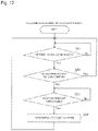
- FIG. 12 is a flowchart for explaining processing of transport to a collection system by the test system according to the second embodiment
- FIG. 13 is a block diagram illustrating a test system according to a third embodiment
- FIG. 14 is a diagram illustrating a state where a test system according to a fourth embodiment is connected to another device
- FIG. 15 is a diagram illustrating a configuration example of a test system according to a fifth embodiment
- FIG. 16 is a block diagram for explaining a measurement unit of a test device, which performs a urine qualitative test
- FIG. 17 is a block diagram for explaining a measurement unit of a test device, which performs a urinary sediment test
- FIG. 18 is a block diagram for explaining a test device, which captures a cell image in a urine sample
- FIG. 19 is a diagram for explaining signal transmission between test devices in the test system according to the fifth embodiment by using external input-output ports.
- FIG. 20 is a flowchart for explaining sample transport processing between test devices of different test types in the test system according to the fifth embodiment.
- test system 10 A configuration of test system 10 according to a first embodiment is described below with reference to FIG. 1 to FIG. 3 .
- test system 10 illustrated in FIG. 1 is a urine test system for performing a urine test.
- Test system 10 includes test device 20 and test device 30 .
- test device 20 and test device 30 are each a urine particle test device (see FIG. 17 ), which is configured to transport a urine sample held in rack 500 to a first loading position P 1 and to test urine particles.
- test system 10 further includes test device 300 .
- test device 300 is a urine qualitative test device (see FIG. 16 ), which is configured to transport the urine sample held in rack 500 and to qualitatively test elements in the urine.
- Test device 20 , test device 30 , and test device 300 are disposed adjacent to one another.
- Test device 300 is disposed on the most upstream side
- test device 20 is disposed on the downstream side thereof
- test device 30 is disposed at the most downstream side.
- Transport paths of the respective test devices are connected to one another so as to enable delivery of rack 500 .
- Test device 20 includes transport unit 20 a , measurement unit 27 , and IPU (Information Processing Unit) 220 formed from a computer.
- Test device 30 includes transport unit 30 a , measurement unit 37 , and IPU 230 .
- Each IPU analyzes measurement data obtained by measurement of the urine sample by the measurement unit, thereby creating a test result.
- IPU 220 ( 230 ) is incorporated into measurement unit 27 ( 37 ), which performs the measurement of the sample in this embodiment, measurement unit 27 ( 37 ) and IPU 220 ( 230 ) may be provided separately.
- IPUs 220 and 230 can be formed from a computer.
- IPU 220 ( 230 ) includes a CPU, a ROM (read only memory), a RAM (random access memory), a storage device such as a hard disk, an input-output interface, a communication interface, and the like.
- the computer functions as IPU 220 ( 230 ) by causing the CPU to execute a control computer program loaded in the RAM.
- the control computer program for causing the computer to function as IPU 220 ( 230 ), and data used for execution of the program are installed in the storage device.
- IPU 220 ( 230 ) An input device such as a keyboard and a mouse is connected to the input-output interface, so that IPU 220 ( 230 ) can accept an input operation from a user.
- IPU 220 ( 230 ) is connected to host computer 210 through the communication interface.
- IPU 220 ( 230 ) is equipped with a display device such as a liquid crystal display, and is able to display a control screen and test result data on the display device.
- test device 20 and test device 30 can be operated in a system measurement mode.
- rack 500 is assigned thereto by master control unit 25 (see FIG. 3 ) to be described later.
- master control unit 25 see FIG. 3
- Each test device 20 or 30 automatically accepts assigned rack 500 , transports rack 500 to each of sample loading positions P 1 and P 2 , and performs the urine test.
- each of test device 20 and test device 30 can be operated in a stand-alone measurement mode to perform the test of the sample independently.
- each test device 20 or 30 can perform the test while transporting rack 500 set manually by a user.
- rack 500 is not assigned to the test device that is set in the stand-alone measurement mode. Accordingly, even if a sample that needs to be urgently tested comes into being, it is possible to handle the sample by changing either test device 20 or test device 30 into the stand-alone measurement mode.
- Test system 10 is communicably connected to host computer 210 .
- Host computer 210 stores measurement orders of respective urine samples, and transmits a measurement order in response to a request from each test device.
- Host computer 210 receives and stores a test result, which is obtained by each test device in accordance with the measurement order.
- a configuration of transport unit 20 a of test device 20 is described with reference to FIG. 2 .
- a direction to first bypass transport unit 21 viewed from measurement unit 27 of test device 20 is referred to as forward (a Y1 direction).
- a vertically downward direction is referred to as downward (a Z2 direction).
- transport unit 20 a includes first bypass transport unit 21 , first supply transport unit 22 , first movable member 23 , and second movable member 24 .
- transport unit 20 a includes master control unit 25 and storage unit 26 (see FIG. 3 ).
- first supply transport unit 22 transport unit 20 a can transport a sample to the first loading position P 1 .
- first bypass transport unit 21 transport unit 20 a can transport the sample to transport unit 30 a connected on the downstream side in a transport direction while causing the sample to bypass the first loading position P 1 .
- First bypass transport unit 21 is disposed on the Y1 side of test device 20 .
- First bypass transport unit 21 includes a belt, which is driven by motor 21 a (see FIG. 3 ).
- First bypass transport unit 21 can transport rack 500 loaded on the belt to test device 30 while causing rack 500 to bypass the first loading position P 1 .
- First bypass transport unit 21 can transport rack 500 in an X1 direction between an X2-side end portion and an X1-side end portion.
- Stop member 21 b is disposed in the vicinity of the X1-side end portion of first bypass transport unit 21 . Stop member 21 b is movable to an interfering position on first bypass transport unit 21 and to a non-interfering position thereon.
- First supply transport unit 22 is disposed on the Y2 side of first bypass transport unit 21 .
- First supply transport unit 22 includes first holder 221 , measurement line 222 , and second holder 223 .
- First holder 221 is sandwiched between measurement line 222 and first bypass transport unit 21 .
- First holder 221 includes stopper member 221 a .
- Stopper member 221 a is disposed in the vicinity of an end portion on the Y2 side of first holder 221 .
- Stopper member 221 a can project to an upper face (a Z1 direction) of first holder 221 by driving a not-illustrated motor.
- stopper member 221 a can restrict movement of rack 500 to measurement line 222 , and retain rack 500 , which contains the sample before being tested, in first holder 221 .
- Measurement line 222 includes two belts, which are arranged in parallel. These belts are driven by motor 222 a (see FIG. 3 ). Measurement line 222 transports the sample supplied from first holder 221 toward second holder 223 via the first loading position P 1 where the sample is loaded. By using the two belts, measurement line 222 can hold two racks 500 respectively in different positions along an X axis, and transport racks 500 individually. Stop member 222 b , which stops racks 500 so as not to move to the X1 side, is provided at an X1-side end portion of measurement line 222 .
- transport unit 20 a is provided with information read unit 253 , which reads sample information attached to the samples that are transported to measurement line 222 .
- the sample information at least includes ID information, which uniquely identifies each sample, and is recorded in a bar code or two-dimensional code format, for example. Based on this sample information, it is possible to identify each sample held in rack 500 and to acquire the measurement order of the identified sample from host computer 210 .
- Information read unit 253 is a reader device, which reads a bar code or a two-dimensional code attached to each sample container, for example.
- Information read unit 253 reads the sample information from the sample located at a reading position P 3 between an upstream end portion of measurement line 222 and the first loading position P 1 .
- Test device 20 is configured to conduct a test of the sample based on the read sample information.
- the sample information may be recorded on a record medium such as an RFID tag, and information read unit 253 may be a reader device configured to read information from the record medium such as the RFID tag.
- Second holder 223 is sandwiched between measurement line 222 and first bypass transport unit 21 .
- second holder 223 includes stopper member 223 a .
- Stopper member 223 a is disposed in the vicinity of an end portion on the Y1 side of second holder 223 .
- Stopper member 223 a can project upward from an upper face of second holder 223 by driving a not-illustrated motor.
- second holder 223 is capable of storing rack 500 that stores tested samples by use of stopper member 223 a .
- test device 20 can be used in the state where stopper member 223 a is caused to constantly project upward from the upper face of second holder 223 .
- Rack 500 retained in second holder 223 can be taken out of test device 20 by a user.
- first movable member 23 is formed substantially into an L-shape.
- First movable member 23 includes first portion 231 and second portion 232 .
- First movable member 23 is movable along the Y axis by a drive force of motor 233 (see FIG. 3 ). Specifically, first movable member 23 can move along the Y axis between an origin position L 1 where first portion 231 and second portion 232 do not interfere with a portion on first bypass transport unit 21 and a backmost position L 3 where rack 500 is fed to measurement line 222 .
- first movable member 23 can be disposed at a stop position L 2 where first portion 231 interferes with the portion on first bypass transport unit 21 while second portion 232 does not interfere with the portion on first bypass transport unit 21 .
- first portion 231 interferes with the portion on first bypass transport unit 21 while second portion 232 does not interfere with the portion on first bypass transport unit 21 .
- First portion 231 is formed at an end portion in the X1 direction of second portion 232 in such a way as to extend in the Y2 direction. First portion 231 is provided for the purpose of stopping rack 500 that moves on first bypass transport unit 21 .
- a power transmission mechanism for transmitting the drive force from motor 233 to first movable member 23 includes torque limiter 233 a (see FIG. 3 ).
- the power transmission mechanism transmits the drive force from motor 233 to first movable member 23 via torque limiter 233 a .
- Torque limiter 233 a is configured to shut off the transmission of the drive force from motor 233 upon application of a load equal to or above a certain level.
- second movable member 24 is formed into a rectangular shape, which extends along the X axis. Second movable member 24 is moved along the Y axis by a drive force of motor 241 (see FIG. 3 ). Specifically, second movable member 24 can move between an origin position L 4 where second movable member 24 does not interfere with a portion on measurement line 222 and a foremost position L 5 where rack 500 is disposed in second holder 223 .
- a power transmission mechanism for transmitting the drive force from motor 241 to second movable member 24 includes torque limiter 241 a (see FIG. 3 ).
- torque limiter 241 a see FIG. 3
- configurations of motor 241 and torque limiter 241 a are respectively the same as those of motor 233 and torque limiter 233 a , and descriptions thereof are omitted.
- Master control unit 25 includes a CPU (Central Processing Unit). Preferably, master control unit 25 is built in transport unit 20 a . A program for causing the CPU to function as master control unit 25 is stored in storage unit 26 . Master control unit 25 executes program 26 a and thereby performs assignment of racks 500 to test device 20 and the test device 30 , which are set in the system measurement mode, and control of transport operations of first supply transport unit 22 and first bypass transport unit 21 .
- CPU Central Processing Unit
- Master control unit 25 is communicably connected to control unit 310 of test device 300 .
- Master control unit 25 is communicably connected to slave control unit 35 of test device 30 .
- Master control unit 25 is communicable with IPU 230 via slave control unit 35 . Accordingly, master control unit 25 can acquire information from IPU 230 as to whether or not test device 30 is operated normally.
- transport unit 30 a of test device 30 is described.
- transport unit 30 a of test device 30 includes second bypass transport unit 31 , second supply transport unit 32 , first movable member 33 , and second movable member 34 .
- the components of transport unit 30 a for transporting rack 500 are the same as those of test device 20 and descriptions thereof are omitted accordingly.
- transport unit 30 a includes slave control unit 35 and storage unit 36 (see FIG. 3 ).
- Program 36 a for causing the CPU to function as slave control unit 35 is stored in storage unit 36 .
- Slave control unit 35 executes program 36 a and thereby controls an operation to transport rack 500 assigned to test device 30 by master control unit 25 .
- Program 26 a and program 36 a may be a common program.
- the program may be designed to be capable of selecting whether the CPU executing the program is caused to function as the master control unit or the CPU is caused to function as the slave control unit.
- slave control unit 35 is built in transport unit 30 a .
- transport unit 30 a is provided with information read unit 353 .
- Information read unit 353 reads the sample information from the sample located at a reading position P 4 between an upstream end portion of measurement line 322 and a second loading position P 2 .
- the sample information acquired by information read unit 353 is transmitted to IPU 230 through slave control unit 35 .
- Test device 30 is configured to conduct a test of the sample based on the read sample information.
- step S 1 of FIG. 4 master control unit 25 determines whether or not there is an acceptance request from test device 300 . Master control unit 25 repeats this determination until there is the acceptance request from control unit 310 of test device 300 . When there is the acceptance request, master control unit 25 moves the processing to step S 2 .
- step S 2 master control unit 25 determines whether or not test device 20 is a previous transport destination of rack 500 .
- master control unit 25 performs the allocation of samples to test device 20 and test device 30 by rotation in a predetermined cycle. Specifically, master control unit 25 allocates racks 500 alternately to test device 20 and test device 30 .
- master control unit 25 moves the processing to step S 3 .
- master control unit 25 moves the processing to step S 7 .
- master control unit 25 moves the processing to step S 3 so as to assign rack 500 to test device 20 .
- step S 3 master control unit 25 checks the status of test device 20 . Specifically, master control unit 25 checks the status of test device 20 in order to determine whether or not test device 20 falls into a condition of being capable of accepting rack 500 (hereinafter referred to as an acceptability condition).
- the acceptability condition means a condition in which test device 20 satisfies three requirements, namely, that test device 20 is normally operated, that test device 20 is not set in the stand-alone measurement mode, and that first holder 221 of test device 20 is not in a full load condition.
- step S 4 master control unit 25 determines whether or not test device 20 can accept rack 500 . Specifically, when master control unit 25 determines that test device 20 satisfies the acceptability condition on the basis of the status of test device 20 checked in step S 3 , master control unit 25 determines that test device 20 can accept rack 500 and moves the processing to step S 5 . On the other hand, master control unit 25 moves the processing to step S 7 if master control unit 25 determines that test device 20 does not satisfy the acceptability condition on the basis of the status of test device 20 checked in step S 3 . In steps S 7 and S 8 , master control unit 25 checks the status of test device 30 and determines whether or not test device 30 can accept rack 500 as described later.
- master control unit 25 assigns rack 500 to test device 30 . Accordingly, master control unit 25 does not assign any samples to a test device causing an error, a test device set in the stand-alone measurement mode, or a test device of which first holder is in a full load condition. As a consequence, it is possible to inhibit the test from stopping.
- step S 5 master control unit 25 transmits a delivery request to test device 300 .
- test device 300 transports rack 500 to test device 20 .
- step S 6 master control unit 25 executes an acceptance processing flow by test device 20 . Details of step S 6 are described later with reference to FIG. 5 . Thereafter, master control unit 25 moves the processing to step S 12 .
- master control unit 25 checks the status of test device 30 . Specifically, as with step S 3 , master control unit 25 checks the status of test device 30 in order to determine whether or not test device 30 falls into the acceptability condition. To be more precise, by means of communication with slave control unit 35 , master control unit 25 checks the status of test device 30 in light of three requirements, namely, that test device 30 is normally operated, that test device 30 is not set in the stand-alone measurement mode, and that first holder 321 of test device 30 is not in a full load condition. Here, regarding the requirement that test device 30 is normally operated out of the acceptability condition of test device 30 , master control unit 25 checks the requirement on the basis of information acquired from IPU 230 through the intermediary of slave control unit 35 .
- step S 8 master control unit 25 determines whether or not test device 30 can accept rack 500 . Specifically, when master control unit 25 determines that test device 30 satisfies the acceptability condition on the basis of the status of test device 30 checked in step S 7 , master control unit 25 determines that test device 30 can accept rack 500 and moves the processing to step S 9 . On the other hand, master control unit 25 moves the processing to step S 3 if master control unit 25 determines that test device 30 does not satisfy the acceptability condition on the basis of the status of test device 30 checked in step S 7 . In steps S 3 and S 4 , master control unit 25 checks the status of test device 20 and determines whether or not test device 20 can accept rack 500 as described previously. When test device 20 can accept rack 500 , master control unit 25 assigns rack 500 to test device 20 .
- master control unit 25 determines whether or not the other test device can accept rack 500 , thereby assigning rack 500 to the test device that can accept rack 500 .
- the transport of rack 500 is not disrupted even when one of the test devices cannot accept rack 500 .
- master control unit 25 repeats the processing in steps S 3 , S 4 , S 7 , and S 8 and stands by until one of the test devices becomes capable of accepting rack 500 .
- step S 9 master control unit 25 transmits an acceptance instruction to slave control unit 35 of test device 30 .
- slave control unit 35 starts drive of a belt by second bypass transport unit 31 and locates first movable member 33 at the stop position L 2 . Details of processing conducted by slave control unit 35 after step S 9 are described later with reference to FIG. 6 .
- step S 10 master control unit 25 starts the drive of the belt by first bypass transport unit 21 .
- first movable member 23 of test device 20 is located at the origin position L 1 .
- step S 11 master control unit 25 transmits a delivery request to test device 300 .
- test device 300 transports rack 500 to test device 20 .
- rack 500 is passed through test device 20 and transported to test device 30 .
- step S 12 master control unit 25 transmits an acceptance completion signal to test device 300 .
- control unit 310 of test device 300 transmits an acceptance request for next rack 500 to master control unit 25 .
- master control unit 25 puts the processing back to step S 1 .
- master control unit 25 can be operated in the stand-alone measurement mode and in the system measurement mode as described previously, master control unit 25 executes the allocation processing of FIG. 4 regardless of which mode is applied. In other words, even when test device 20 is set in the stand-alone measurement mode, master control unit 25 can continuously execute the determination of the transport destination of the sample, and the issuance of the instructions to slave control unit 35 . In this case, master control unit 25 executes the control of the transport of the rack by test device 20 in the stand-alone measurement mode (step S 57 in FIG. 9 ) in parallel with the allocation processing of FIG. 4 . It is therefore not necessary to interrupt system measurement even in a situation where test device 20 including master control unit 25 needs to be set in the stand-alone measurement mode.
- This processing is a subroutine of step S 6 in the allocation processing (see FIG. 4 ), which is conducted by master control unit 25 .
- step S 21 master control unit 25 determines whether or not rack 500 can be supplied to measurement line 222 .
- the state where rack 500 can be supplied to measurement line 222 is a state where at least one of the two belts of measurement line 222 does not hold rack 500 , i.e., a state where the belt is empty.
- master control unit 25 determines that rack 500 cannot be supplied to measurement line 222
- master control unit 25 moves the processing to step S 22 .
- master control unit 25 determines that rack 500 can be supplied to measurement line 222
- master control unit 25 moves the processing to step S 23 .
- step S 22 master control unit 25 causes stopper member 221 a to project to first holder 221 .
- step S 23 master control unit 25 activates first bypass transport unit 21 and moves first movable member 23 to the stop position L 2 .
- rack 500 delivered from test device 300 is transported in the X1 direction by first bypass transport unit 21 , and comes into contact with first portion 231 (see FIG. 2 ) of first movable member 23 and is hence stopped.
- An arrival of rack 500 at a rack stop position by means of first movable member 23 is detected with a not-illustrated sensor.
- master control unit 25 When rack 500 arrives at the rack stop position, master control unit 25 performs feed processing by using first movable member 23 in step S 24 . Specifically, master control unit 25 drives motor 233 in such a drive amount to move first movable member 23 to the backmost position L 3 , and moves rack 500 in the Y2 direction. At this time, the arrival position of rack 500 varies depending on whether stopper member 221 a is projecting or not projecting.
- master control unit 25 puts first movable member 23 back to the origin position L 1 .
- step S 25 master control unit 25 determines whether or not first holder 221 of test device 20 is in the full load condition on the basis of the number of pulses of motor 233 when first movable member 23 returns to the origin position L 1 .
- the number of pulses generated by motor 233 when first movable member 23 returns to the origin position L 1 corresponds to the position on the Y axis of rack 500 located on the foremost side (in the Y1 direction) in first holder 221 . This corresponds to the number of racks 500 present in first holder 221 .
- master control unit 25 can calculate the number of racks 500 in first holder 221 on the basis of the number of pulses during the return to the origin position L 1 , and determine whether or not first holder 221 is in the full load condition based thereon. When master control unit 25 determines that first holder 221 is in the full load condition, master control unit 25 moves the processing to step S 26 . On the other hand, when master control unit 25 determines that first holder 221 is not in the full load condition, master control unit 25 terminates the acceptance processing and moves the processing to step S 12 (see FIG. 4 ).
- step S 26 master control unit 25 performs processing to store information, which indicates that first holder 221 of test device 20 is in the full load state, in storage unit 26 . Thereafter, master control unit 25 terminates the acceptance processing and moves the processing to step S 12 (see FIG. 4 ).
- step S 31 slave control unit 35 determines whether or not there is the acceptance instruction for rack 500 from master control unit 25 . Specifically, slave control unit 35 determines whether or not the acceptance instruction for rack 500 is received from master control unit 25 as a consequence of step S 9 in the allocation processing (see FIG. 4 ). Slave control unit 35 repeats this determination until there is the acceptance instruction for rack 500 from master control unit 25 . When there is the acceptance request, slave control unit 35 moves the processing to step S 32 .
- step S 32 slave control unit 35 determines whether or not rack 500 can be supplied to measurement line 322 .
- slave control unit 35 determines that rack 500 cannot be supplied to measurement line 322 .
- slave control unit 35 moves the processing to step S 33 .
- slave control unit 35 moves the processing to step S 34 .
- step S 33 slave control unit 35 causes stopper member 321 a to project to first holder 321 .
- step S 34 slave control unit 35 activates second bypass transport unit 31 and moves first movable member 33 to the stop position L 2 .
- rack 500 having passed through test device 20 is transported in the X1 direction by second bypass transport unit 31 , and comes into contact with first portion 331 (see FIG. 2 ) of first movable member 33 and is hence stopped.
- An arrival of rack 500 at a rack stop position by means of first movable member 33 is detected with a not-illustrated sensor.
- step S 35 slave control unit 35 performs processing to feed rack 500 into first holder 321 . Specifically, slave control unit 35 drives motor 333 in such a drive amount to move first movable member 33 to the backmost position L 3 . Thereafter, slave control unit 35 puts first movable member 33 back to the origin position L 1 .
- step S 36 slave control unit 35 determines whether or not first holder 321 of test device 30 is in the full load condition.
- slave control unit 35 determines that first holder 321 is in the full load condition based on the number of return pulses of motor 333 when first movable member 33 returns to the origin position L 1 .
- slave control unit 35 moves the processing to step S 37 .
- the slave control unit 35 terminates the acceptance processing when slave control unit 35 determines that first holder 321 is not in the full load condition.
- step S 37 slave control unit 35 performs the processing to store information, which indicates that first holder 321 of test device 30 is in the full load state, in storage unit 36 . Thereafter, slave control unit 35 terminates the acceptance processing.
- processing of transport to the loading position by test device 20 is described with reference to FIG. 2 and FIG. 7 .
- This processing is conducted by master control unit 25 .
- This processing is processing to be executed both in the system measurement mode and in the stand-alone measurement mode.
- slave control unit 35 the same transport processing as that of test device 20 is conducted by slave control unit 35 as well. For this reason, only the processing of transport to the loading position by test device 20 is described herein and the description concerning the processing of transport to the loading position by test device 30 is omitted.
- step S 41 master control unit 25 determines whether or not rack 500 remains in first holder 221 . Master control unit 25 repeats this processing until master control unit 25 determines that rack 500 remains in first holder 221 . Master control unit 25 moves the processing to step S 42 when master control unit 25 determines that rack 500 remains in first holder 221 .
- step S 42 master control unit 25 determines whether or not rack 500 can be supplied to measurement line 222 . Master control unit 25 repeats this processing until master control unit 25 determines that rack 500 can be supplied to measurement line 222 . Master control unit 25 moves the processing to step S 43 when master control unit 25 determines that rack 500 can be supplied to measurement line 222 .
- step S 43 master control unit 25 moves stopper member 221 a below first holder 221 (in the Z2 direction), and performs processing to feed rack 500 to measurement line 222 .
- master control unit 25 drives motor 233 in such a drive amount to move first movable member 23 to the backmost position L 3 .
- master control unit 25 determines that first holder 221 in test device 20 is no longer in the full load condition as a consequence of the processing in step S 43 , and deletes the information indicating the full load condition, which is stored in storage unit 26 in step S 26 (see the acceptance processing by master control unit 25 of FIG. 5 ).
- step S 44 master control unit 25 operates measurement line 222 such that the sample containers held in rack 500 are disposed in order at the reading position P 3 .
- step S 45 master control unit 25 reads the sample information with information read unit 253 .
- Information read unit 253 reads the sample information attached to the sample containers supplied to the reading position P 3 .
- Master control unit 25 acquires the read sample information from information read unit 253 and transmits the sample information to IPU 220 .
- steps S 44 and S 45 the sample information on all the sample containers held in rack 500 is transmitted to IPU 220 .
- step S 46 master control unit 25 operates measurement line 222 such that sample containers held in rack 500 are disposed in order at the first loading position P 1 .
- Measurement unit 27 sequentially aspirates the samples from the sample containers supplied to the first loading position P 1 , and performs measurement concerning urine tests.
- master control unit 25 moves measurement line 222 so as to transport rack 500 to the end portion on the X1-direction side.
- step S 47 master control unit 25 performs processing to feed rack 500 into second holder 223 .
- master control unit 25 drives motor 241 in such a drive amount to move second movable member 24 to the foremost position L 5 .
- sample aspiration processing in test device 20 and test device 30 is described with reference to FIG. 2 , FIG. 3 , and FIG. 8 .
- This processing is processing on the part of measurement units 27 and 37 to be conducted in parallel with the transport processing illustrated in FIG. 7 .
- This processing is conducted by measurement units 27 and 37 under control of IPU 220 and IPU 230 .
- the sample aspiration processing by test device 20 is described as an example. However, the same processing is executed by test device 30 as well.
- step S 141 of FIG. 9 IPU 220 determines whether or not the sample information is acquired from master control unit 25 .
- IPU 220 stands by while repeating the determination of step S 141 until the sample information is transmitted from master control unit 25 .
- IPU 220 sets the samples identified by the sample information as objects of aspiration in step S 142 . Accordingly, at the point when the sample information is read by information read unit 253 at the reading position P 3 , all the samples held in rack 500 are set as the objects of aspiration.
- step S 143 IPU 220 inquires of host computer 210 about the measurement orders of the samples identified by the sample information.
- step S 144 IPU 220 determines whether or not there is the measurement order for each of the identified samples.
- IPU 220 causes measurement unit 27 to perform an operation to aspirate the sample in step S 145 . Specifically, when the sample for which the measurement order is determined to be present is transported to the first loading position P 1 , measurement unit 27 performs aspiration of the sample. In step S 146 , measurement unit 27 performs measurement of the aspirated sample.
- IPU 220 excludes the sample without the measurement order from the objects of aspiration, thereby cancelling aspiration of this sample by measurement unit 27 in step S 147 .
- each sample whose sample information is read out at the reading position P 3 is once set as the object of aspiration, and then the setting as the object of aspiration is cancelled if the measurement order for the relevant sample is determined to be not present.
- the sample container skips the aspiration by measurement unit 27 .
- step S 146 or S 147 IPU 220 brings the processing back to step S 141 , and performs the processing of the next sample.
- mode change processing in test device 20 and test device 30 is described with reference to FIG. 2 , FIG. 3 , and FIG. 9 .
- This processing is conducted by master control unit 25 and slave control unit 35 .
- master control unit 25 a case of being conducted by master control unit 25 is described as an example. Note that the same processing is executed by slave control unit 35 as well.
- test device 25 When test device 25 is started, master control unit 25 sets test device 20 in the system measurement mode in step S 51 .
- step S 52 master control unit 25 determines whether or not mode change switch 251 (see FIG. 2 ) is pressed. Master control unit 25 repeats this processing until mode change switch 251 is operated by a user. When mode change switch 251 is operated, master control unit 25 moves the processing to step S 53 .
- step S 53 master control unit 25 sets test device 20 in the stand-alone measurement mode.
- Master control unit 25 stores information, which indicates that the measurement mode is set in the stand-alone measurement mode, in storage unit 26 (see FIG. 3 ).
- storage unit 26 see FIG. 3 .
- master control unit 25 can transport rack 500 from test device 300 to test device 30 while operating test device 20 alone.
- step S 54 master control unit 25 determines whether or not residual rack 500 remains in first holder 221 .
- master control unit 25 determines whether or not there is rack 500 , which is accepted by first holder 221 in the system measurement mode but the measurement thereof is yet to be completed.
- master control unit 25 repeats this determination until no rack 500 remains in first holder 221 .
- the transport processing flow in FIG. 7 is continued during this period as well. Accordingly, even in the case of setting in the stand-alone measurement mode, the transport to the first loading position P 1 and the measurement of the samples are continued regarding rack 500 remaining in first holder 221 .
- step S 55 master control unit 25 enables measurement start switch 252 (see FIG. 2 ) provided to test device 20 .
- Measurement start switch 252 is a switch for instructing start of the measurement of rack 500 set in first holder 221 in the stand-alone measurement mode. Accordingly, by enabling measurement start switch 252 in step S 55 , the user can set rack 500 in first holder 221 and execute the measurement in the stand-alone measurement mode.
- step S 56 master control unit 25 determines whether or not measurement start switch 252 is pressed. When measurement start switch 252 is pressed, master control unit 25 moves the processing to step S 57 . When measurement start switch 252 is not pressed, master control unit 25 moves the processing to step S 58 .
- step S 57 master control unit 25 executes a processing flow of transport to the loading position regarding rack 500 set in first holder 221 by the user. Specifically, as illustrated in FIG. 7 , master control unit 35 determines whether or not rack 500 is set in first holder 221 by the user (S 41 ). When rack 500 is set therein, master control unit 25 determines whether or not rack 500 can be supplied to measurement line 222 (S 42 ). When rack 500 can be supplied thereto, master control unit 25 feeds rack 500 to measurement line 222 , and controls transport unit 20 a in such a way as to transport rack 500 to the reading position P 3 and the first sample loading position P 1 (S 43 , S 44 , and S 46 ) in order.
- Master control unit 25 transmits the read sample information to IPU 220 (S 45 ). Measurement unit 27 loads the samples and performs the urine tests based on the sample information. When the urine tests are completed, master control unit 25 controls transport unit 20 a in such a way as to feed rack 500 into second holder 223 (S 47 ). This processing flow is the same as the processing described by using FIG. 7 and detailed descriptions are therefore omitted.
- step S 58 master control unit 25 determines whether or not mode change switch 251 is pressed. Master control unit 25 puts the processing back to step S 51 when mode change switch 251 is pressed. Master control unit 25 puts the processing back to step S 56 when mode change switch 251 is not pressed.
- the samples can be assigned to test device 20 and test device 30 by using master control unit 25 of test device 20 .
- the assignment of the samples previously performed by a dedicated computer as a transport controller can be realized by use of the control unit of transport unit 30 a .
- test system 100 A configuration of test system 100 according to a second embodiment is described below with reference to FIG. 2 , FIG. 10 , and FIG. 11 .
- This second embodiment describes test system 100 configured to collect rack 500 containing tested samples by use of collection system 400 installed on the X1 side of test device 30 , which is different from the first embodiment that is configured to retain rack 500 containing the tested samples in second holder 223 .
- the same components as those in the above-described first embodiment are denoted by the same reference numerals and descriptions thereof are omitted.
- test system 100 is communicably connected to test device 300 and to collection system 400 , respectively.
- Master control unit 125 is communicably connected to slave control unit 135 of test device 30 .
- Master control unit 125 is communicably connected to control unit 410 of collection system 400 .
- Master control unit 125 acquires information, which indicates whether or not collection holder 420 (see FIG. 10 ) of collection system 400 is in a full load condition, from control unit 410 of collection system 400 .
- test system 100 can transport rack 500 (see FIG. 2 ), which is retained in first holder 221 of test device 20 , to collection system 400 via first bypass transport unit 21 and second bypass transport unit 31 .
- Test system 100 can transport rack 500 , which is retained in first holder 321 of test device 30 , to collection system 400 via second bypass transport unit 31 .
- step S 61 master control unit 125 determines whether or not there are any racks 500 in the second holders. Specifically, master control unit 125 determines whether or not rack 500 remains in any of second holder 223 of test device 20 and second holder 323 of test device 30 . The determination as to whether or not rack 500 remains therein is performed by detecting the presence of the rack in second holder 223 with a not-illustrated sensor.
- Master control unit 125 repeats the determination in step S 61 until rack 500 is retained in any of second holder 223 of test device 20 and second holder 323 of test device 30 .
- master control unit 125 moves the processing to step S 62 .
- step S 62 master control unit 125 determines whether or not collection holder 420 (see FIG. 10 ) of collection system 400 is in the full load condition. Master control unit 125 moves the processing to step S 63 when collection holder 420 of collection system 400 is not in the full load condition.
- master control unit 125 puts the processing back to step S 61 when collection holder 420 of collection system 400 is in the full load condition. Meanwhile, when master control unit 125 determines that both of second holder 223 of test device 20 and second holder 323 of test device 30 are in the full load condition, master control unit 125 does not transmit a delivery request to test device 300 . As a consequence, the transport of next rack 500 from test device 300 is interrupted temporarily.
- step S 63 master control unit 125 determines whether or not the bypass transport units are available. Specifically, master control unit 125 determines whether or not it is in the course of performing processing to transport rack 500 , which contains samples yet to be measured, to any of first holder 221 of test device 20 and first holder 321 of test device 30 . If first bypass transport unit 21 or second bypass transport unit 31 is being used for transporting rack 500 , which contains the samples yet to be measured, to any of the test devices, then master control unit 125 repeats this determination until master control unit 125 determines that the bypass transport units are available. Master control unit 125 moves the processing to step S 64 when master control unit 125 determines that the bypass transport units are available.
- step S 64 master control unit 125 transports rack 500 to collection system 400 .
- master control unit 125 moves stopper member 223 a downward, moves stop member 21 b to such a position where stop member 21 b does not interfere with first bypass transport unit 21 , and drives first bypass transport unit 21 .
- master control unit 125 sends slave control unit 135 an instruction to allow passage of rack 500 .
- slave control unit 135 locates first movable member 31 at the origin position L 1 , moves stop member 31 b to a non-interference position, and drive second bypass transport unit 31 . In this state, master control unit 125 moves second movable member 24 in the Y1 direction.
- Rack 500 is transported from second holder 223 to collection system 400 via first bypass transport unit 21 and second bypass transport unit 31 .
- master control unit 125 sends slave control unit 135 an instruction to transport rack 500 to collection system 400 .
- slave control unit 135 moves stopper member 323 a downward, moves stop member 31 b to such a position where stop member 31 b does not interfere with second bypass transport unit 31 , and drives second bypass transport unit 31 .
- slave control unit 135 moves second movable member 34 in the Y1 direction.
- rack 500 is transported from second holder 323 of test device 30 to collection system 400 .
- master control unit 125 puts the processing back to step S 61 .
- racks 500 can be automatically collected by collection system 400 .
- test system 110 A configuration of test system 110 according to a third embodiment is described below with reference to FIG. 13 .
- This third embodiment is the same as the first embodiment, except that the test device that includes the master control unit and the test device that includes the slave control unit switch places with each other.
- the same components as those in the above-described first embodiment are denoted by the same reference numerals and descriptions thereof are omitted.
- Master control unit 225 of test device 20 on a downstream side performs the assignment of samples to test device 20 on the downstream side and test device 30 on an upstream side as well as the control of the operations to transport the sample assigned to test device 20 in accordance with the same methods as those of the first and second embodiments.
- slave control unit 235 of test device 30 on the upstream side controls the operation to transport the sample assigned to test device 30 by master control unit 225 on the downstream side.
- Master control unit 225 can communicate with control unit 310 of test device 300 through the intermediary of slave control unit 235 .
- master control unit 225 can receive the acceptance request (S 1 in FIG. 4 ) from control unit 310 through the intermediary of slave control unit 235 , and transmit the delivery request (S 5 and S 11 in FIG.
- control unit 310 may be caused to function as the master control unit.
- This configuration can also exert the functions similar to those of the first and second embodiments.
- test system 120 A configuration of test system 120 according to a fourth embodiment is described below with reference to FIG. 14 .
- configurations of test device 20 and test device 30 are different from those of the first and second embodiments.
- Test device 20 includes one transport path 250 .
- Test device 30 includes one transport path 350 .
- Transport path 250 and transport path 350 are connected in series.
- Test device 20 grips rack 500 transported onto transport path 250 by using gripper 280 and takes rack 500 out of transport path 250 , then moves rack 500 in the Y2 direction, and stows rack 500 into measurement unit 27 .
- Test device 20 aspirates the samples out of the respective sample containers in stowed rack 500 .
- Test device 30 also has the same configuration.
- Test device 20 can transport rack 500 to test device 30 located downstream via transport path 250 while test device 20 is taking rack 500 out by using gripper 280 .
- test device 20 and test device 30 can exert the same functions as those of the first and second embodiments.
- test system 120 it is possible to simplify test system 120 as with the first embodiment.
- test system 130 A configuration of test system 130 according to a fifth embodiment is described below with reference to FIG. 15 to FIG. 19 .
- the fifth embodiment describes a case in which test system 130 is configured as test lines each including multiple test devices of multiple kinds with different test types.
- test system 130 of the fifth embodiment includes test device 601 , test device 602 , test device 603 , and test device 604 each configured to transport and test samples.
- Test device 601 and test device 602 are devices, which perform tests of a first test type.
- Test device 603 and test device 604 are devices, which perform tests of a second test type different from the first test type.
- FIG. 15 illustrates a configuration example in which two test devices of the first test type and two test devices of the second test type are provided, respectively.
- Test device 601 includes master control unit 621 , which performs assignment of samples to test device 601 and test device 602 , and control of a transport operation of the sample assigned to test device 601 .
- Test device 602 includes slave control unit 622 , which controls a transport operation of the sample assigned to test device 602 by master control unit 621 .
- Test device 603 includes master control unit 623 , which performs assignment of samples to test device 603 and test device 604 , and control of a transport operation of the sample assigned to test device 603 .
- Test device 604 includes slave control unit 624 , which controls a transport operation of the sample assigned to test device 604 by master control unit 623 .
- Master control unit 621 of test device 601 assigns the samples to test device 601 and test device 602 , which perform the tests of the same first test type. Master control unit 621 does not assign any samples to test devices, which perform tests of a different test type. Master control unit 623 of test device 603 assigns the samples to test device 603 and test device 604 , which perform the tests of the same second test type. Master control unit 623 does not assign any samples to test devices, which perform tests of a different test type.
- each of master control unit 621 an master control unit 623 performs the assignment of the samples only to the test devices, which perform the tests of the common test type.
- the control unit of any one of such test devices may be configured as the master control unit while the control units of the rest of the test devices may be configured as the slave control units.
- master control unit 621 of test device 601 and master control unit 623 of test device 603 can perform the assignment of the samples to test device 602 and test device 604 , which perform the tests of the same types, respectively.
- the structure of test system. 130 can be simplified.
- test devices of different test types involve different time periods required for sample processing, different numbers of samples treated as test objects, and so forth. Accordingly, if a single master control unit performs the assignment to all the test devices in test system 130 , the control for performing the assignment is complicated. On the other hand, by adopting the above-described configuration, each of master control unit 621 and master control unit 623 only needs to perform the assignment of the samples to the test devices of the same test type. Thus, the control of the assignment processing can be simplified.
- each of the test devices is a device configured to test urine samples.
- the test types in testing urine samples include a urine qualitative test and a urinary sediment test.
- the urine qualitative test is a test to measure chemical components in urine, which are related to a clinical test.
- the urinary sediment test is a test to measure particles (sediments) in urine and to count and classify the particles.
- a test of a urine sample there may be a case in which a microscopic image of cells in urine is captured and then subjected to microscopic examination to be checked by a doctor and others.
- capture of a cell image for the microscopic examination is also included as another test type.
- the test types to be conducted by the test devices may be arbitrarily changed in accordance with the intended use of the test system.
- the first test type is the urine qualitative test.
- test device 601 and test device 602 which perform the tests of the first test type are each a test device configured to perform measurement of a urine sample by detecting colors on a test strip to which the urine sample is applied.
- the second test type is the urinary sediment test, for example.
- test device 603 and test device 604 which perform the tests of the second test type are each a test device configured to perform measurement of particles in a urine sample by flow cytometry.
- test system 130 capable of performing the urine qualitative test, which is definitely conducted in the urine test, by use of test device 601 and test device 602 , and performing the urinary sediment test, which is conducted depending on a result of the qualitative test, by use of test device 603 and test device 604 .
- the assignment of the samples to the test devices can be performed on the basis of the test type. Accordingly, it is possible to suppress complication of the configuration of test system 130 .
- Test system 130 may also include a test device of a third test type.
- the third test type is the capture of a cell image in a urine sample, for example.
- test system 130 may further include test device 605 , which is configured to receive a sample tested by test device 603 or test device 604 , and to capture a cell image in the urine sample.
- test device 605 which is configured to receive a sample tested by test device 603 or test device 604 , and to capture a cell image in the urine sample.
- FIG. 15 illustrates an example of test system 130 provided with the five test devices.
- Test system 130 may include two or more test devices of the third test type.
- test device 605 it is also possible to provide test device 605 with a master control unit and to cause the master control unit to perform assignment of the samples.
- Test device 605 includes control unit 625 . Meanwhile, each of test device 601 , test device 602 , test device 603 , test device 604 , and test device 605 includes communication unit 641 , external input-output port 642 (which is indicated as “external I/O port” in FIG. 15 ), and information read unit 643 . Other configurations of each test device are similar to those in the first embodiment. Specifically, except for configurations of measurement units, test device 601 and test device 603 each provided with the master control unit have the same configuration as that of test device 20 illustrated in FIG. 2 and FIG. 3 , while test device 602 and test device 604 each provided with the slave control unit have the same configuration as that of test device 30 illustrated in FIG. 2 and FIG. 3 . The configurations of the measurement units are to be described later.
- test devices are arranged in series so as to enable delivery of racks 500 .
- Racks 500 which hold samples are transported in order from an upstream side (test device 601 side) to a downstream side (test device 605 side).
- test system 130 may be provided with collection system 400 disposed at the lowermost stream and loading system 450 disposed at the uppermost stream.
- Collection system 400 is the same as that in the above-described second embodiment.
- Loading system 450 can install multiple racks 500 holding samples and supply racks 500 to the test devices on the downstream side.
- test device 601 and test device 603 each provided with the master control unit receive the samples earlier than test device 602 and test device 604 each provided with the slave control unit.
- test device 601 and test device 603 are disposed upstream of test device 602 and test device 604 , respectively, and are configured to receive the samples transported from the upstream side.
- rack 500 transported from the upstream side is first delivered to test device 601 or test device 603 provided with the master control unit. Accordingly, it is not necessary to monitor whether or not rack 500 is delivered from outside to test device 602 or test device 604 .
- test device 602 is disposed adjacent to the upstream side of test device 603 .
- test device 603 receives rack 500 holding the samples from test device 602 on the upstream side.
- master control unit 623 acquires a status from slave control unit 624 of test device 604 and determines a test device, which can accept rack 500 holding the samples.
- test device 603 or test device 604 can perform a test of the second test type promptly after test device 601 or test device 602 conducts a test of the first test type.
- the assignment processing (see FIG. 4 ) and the acceptance processing (see FIG. 5 and FIG. 6 ) of the samples between test device 601 and test device 602 are similar to those in the above-described first embodiment. Specifically, master control unit 621 of test device 601 acquires the number of racks 500 stored in test device 602 (step S 7 of FIG. 4 ) from slave control unit 622 of test device 602 , and determines whether or not rack 500 is acceptable (step S 8 of FIG. 4 ) based on the number of racks 500 .
- Master control unit 623 of test device 603 acquires the number of racks 500 stored in test device 604 from slave control unit 624 of test device 604 , and determines whether or not rack 500 is acceptable based on the number of racks 500 .
- the test processing can be continued by assigning rack 500 to another test device without stopping test system 130 .
- the transport of the samples between a test device on the upstream side and a test device on the downstream side can be performed by means of exchange of signals between adjacent test devices.
- master control unit 623 determines whether or not test device 603 and test device 604 can accept rack 500 , and constantly notifies test device 602 , which is located adjacent on the upstream side, of the acceptability of rack 500 .
- master control unit 623 accepts rack 500 and determines a test device out of test device 603 and test device 604 , which can accept the samples. In this case, it is not necessary to cause master control unit 621 and master control unit 623 to communicate with each other, and the sample delivery processing can thus be simplified.
- connection to establish communications among the test device it is possible to adopt a connection method common to all the test devices or to adopt multiple different communication methods.
- a communication method between master control unit 621 and slave control unit 622 or between master control unit 623 and slave control unit 624 , where the assignment processing takes place may be different from a communication between master control unit 623 and slave control unit 622 where the assignment processing does not take place.
- the communication method between the test devices having the test type in common may be different from the communication method between the test devices having the different test types.
- test device 601 is network-connected to test device 602 through communication units 641 .
- test device 603 is network-connected to test device 604 through communication units 641 .
- Test device 602 and test device 603 whose test types are different, are configured to be connectable through external input-output ports 642 , which transmit a smaller amount of information than that by means of the network connection.
- Communication units 641 perform the network communication based on the TCP/IP protocol in compliance with the Ethernet (registered trademark) standard, for example.
- External input-output ports 642 are connected to each other through a signal line, and perform signal transmission by switching on (or a high level) and off (or a low level).
- test devices with the test type in common can ensure a sufficient amount of information transmission for the sample assignment processing and the transport control by means of the network connection between communication units 641 .
- the sample delivery processing can be achieved with a minimum required amount of information transmission by exchanging on-off signals between external input-output ports 642 , for example.
- the sample delivery processing can be achieved with the minimum required communication through external input-output ports 642 in the case of providing test devices manufactured by different manufacturers depending on the test types.
- compatibility in test system 130 is easily ensured.
- connection between loading system 450 and test device 601 as well as between collection system 400 and test device 605 is also established through external input-output ports 642 .
- illustration of the external input-output ports of collection system 400 and loading system 450 is omitted.
- each sample to be assigned only needs to be uniquely identifiable within a group of the test devices of the same test type.
- master control unit 621 only needs to be able to uniquely identify each sample or rack 500 within the group composed of test device 601 and test device 602
- master control unit 623 only needs to be able to uniquely identify each sample or rack 500 within the group composed of test device 603 and test device 604 .
- the identification of each sample for achieving the sample assignment may use the sample information to be read by information read unit 643
- the sample may instead be provided with an identification number, which is valid only in the group of the test devices of the same test type.
- each of master control unit 621 and master control unit 623 is configured to provide rack 500 holding samples with an identification number upon receipt of the samples from the upstream side, and to assign the samples based on the identification number.
- the configuration of test system 130 can be further simplified.
- the identification numbers may adopt consecutive numbers starting from 1, for example.
- An upper limit of the identification numbers may be defined equal to a maximum number of racks 500 , which can exist in the group of the test devices of the same test type.
- FIG. 15 there are assumed to be test device 601 and test device 602 as the group of the first test type, and each device is assumed to be capable of locating seven racks 500 in first holder 221 ( 321 ), seven racks 500 in second holder 223 ( 323 ), and two racks 500 on measurement line 222 ( 322 ), respectively.
- thirty-two racks 500 calculated by 16 ⁇ 2 may exist at the maximum in the group. Accordingly, it is only necessary to provide thirty-two identification numbers from 1 to 32.
- FIG. 15 illustrates an example in which an identification number of 1 (see a circled number) is set to rack 500 located ahead in test device 602 and an identification number of 2 is set to rack 500 located behind.
- each test device can read the sample information attached to the samples sent to measurement line 222 ( 322 ) by using information read unit 643 , and conduct the tests of the samples based on the read sample information.
- the processing efficiency of test system 130 is not deteriorated by spending time for the read processing. Hence, the tests of the samples can be promptly conducted.
- each control unit out of master control unit 621 , master control unit 623 , slave control unit 622 , and slave control unit 624 determines whether or not to conduct the test of the sample based on the sample information read by information read unit 643 from the sample held in rack 500 transported to measurement line 222 ( 322 ). Based on the read information, each control unit determines whether or not there is the measurement order in host computer 210 , and performs aspiration of the sample when there is the measurement order.
- each test device at a destination of the assignment can determine whether or not to conduct the test of each sample based on the sample information without providing the loading system 450 with a dedicated reading device for reading the sample information in advance, for example.
- the configuration of test system 130 can be further simplified.
- host computer 210 may be a management server, which manages test information on the entire facility in which test system 130 is installed, or a management computer for managing test system 130 .
- host computer 210 is the management computer, host computer 210 is network-connected to a management server, which manages the test information on the entire facility, and mediates the exchange of inquiries about the measurement orders and delivery of the measurement orders between the management server and test system 130 .
- test device 601 and test device 602 of the first test type includes measurement unit 650 for detecting colors on a test strip.
- measurement unit 650 applies a urine sample to a test strip and measures color reactions on the test strip, thereby measuring test item elements contained in the urine.
- Measurement unit 650 sends the test strip from test strip feeder 651 storing the test strips out to a predetermined test position.
- Sample supply unit 652 supplies the urine sample, which is aspirated from the sample container either at the first loading position P 1 or at the second loading position P 2 , to the test strip.
- Measurement unit 650 irradiates the test strip with measurement light from light source unit 653 and receives the measurement light with color sensor 654 , thereby measuring the color reactions on the test strip.
- the measurement items include, for example, glucose, protein, bilirubin, ph (hydrogen ion exponent), and the like.
- test device 603 and test device 604 of the second test type includes measurement unit 660 provided with a flow cytometer.
- measurement unit 660 a measurement specimen is prepared from the urine sample, which is aspirated from the sample container either at the first loading position P 1 or at the second loading position P 2 , by using a reagent such as a staining solution.
- specimen supply unit 661 supplies the measurement specimen to flow cell 662 .
- Light source unit 663 irradiates flow cell 662 with measurement light.
- Light receiving unit 664 , light receiving unit 665 , and light receiving unit 666 measure forward scattered light, side scattered light, and fluorescence, respectively, which originate from particles in the measurement specimen flowing in flow cell 662 .
- Optical system 667 including a lens, a spectroscopic element, and the like is provided in each space between flow cell 662 and each of light source unit 663 , light receiving unit 664 , light receiving unit 665 , and light receiving unit 666 .
- IPU 220 or 230 (see FIG. 15 ) of measurement unit 660 counts and classifies the particles by analyzing light reception signals thus obtained.
- the particles include, for example, red blood cells, white blood cells, epithelial cells, casts, bacteria, and the like contained in the urine sample.
- Test device 605 of the third test type includes measurement unit 670 provided with an image capturing unit for capturing a cell image in the urine.
- sample supply unit 671 supplies the urine sample aspirated at a loading position to specimen container 673 disposed on movable stage 672 .
- Light source unit 674 irradiates specimen container 673 with illumination light.
- Image sensor 675 captures a cell image in specimen container 673 through objective lens 676 .
- IPU 240 (see FIG. 15 ) of measurement unit 670 stores the captured image acquired from image sensor 675 .
- FIG. 19 illustrates a configuration example in which master control unit 623 of test device 603 and slave control unit 622 of test device 602 , which are connected to each other through external input-output ports 642 , perform signal transmission concerning transport of a sample by use of four ports.
- each external input-output port 642 includes OPTION port 681 , ERR port 682 , READY port 683 , and MOVE port 684 .
- OPTION port 681 represents a status of a power source of the test device. For example, an ON level represents that the power source is on while an OFF level represents that the power source is off.
- ERR port 682 represents presence of an error in the test device. For example, an ON level represents that an error is not present while an OFF level represents that an error is present.
- READY port 683 represents a status whether or not the test device can accept rack 500 .
- an ON level represents a status of being acceptable while an OFF level represents a state of being not acceptable.
- MOVE port 684 represents a status of transport of rack 500 in the test device.
- an ON level represents a status of being in the course of transport while an OFF level represents a state of being not in the course of transport.
- Master control unit 623 on the downstream side constantly notifies slave control unit 622 on the upstream side of the status of the power source and the presence of an error by using OPTION port 681 and ERR port 682 .
- the transport of rack 500 is performed when the test device on the downstream side is in the state where the power source is on, an error is not present, and rack 500 is acceptable.
- slave control unit 622 on the upstream side performs the transport of rack 500 to the downstream side when OPTION port 681 , ERR port 682 , and READY port 683 of master control unit 623 on the downstream side are each at the ON level.
- slave control unit 622 on the upstream side raises MOVE port 684 from the OFF level to the ON level, and sends rack 500 out to the downstream side.
- Master control unit 623 on the downstream side starts acceptance of rack 500 based on the change of MOVE port 684 from the OFF level to the ON level. Accordingly, the raise of MOVE port 684 to the ON level corresponds to the acceptance request made to the device on the downstream side (see step S 1 of FIG. 4 ).
- master control unit 623 on the downstream side changes READY port 683 to the OFF level.
- slave control unit 622 on the upstream side understands that rack 500 is delivered. Accordingly, the change of READY port 683 to the OFF level corresponds to the acceptance completion signal sent to the device on the upstream side (see step S 12 of FIG. 4 ).
- transport processing of rack 500 between the test devices of different test types is described with reference to FIG. 15 and FIG. 20 .
- This processing is the control to be performed between the master control unit on the downstream side and the slave control unit on the upstream side, which are adjacent to each other.
- the transport between test device 602 and test device 603 in the configuration example of FIG. 15 is described as an example.
- slave control unit 622 of test device 602 on the upstream side determines whether or not to perform the transport of rack 500 out of test device 601 to the downstream side. Specifically, slave control unit 622 conducts the determination through communication units 641 as to whether or not there is an acceptance request for rack 500 from master control unit 621 of the same test type to test device 603 on its downstream side. Meanwhile, if there is no acceptance request, slave control unit 622 on the upstream side determines whether or not rack 500 is to be transported out of test device 602 to test device 603 on the downstream side in step S 72 . Slave control unit 622 on the upstream side repeats the determinations in steps S 71 and S 72 until it is determined that rack 500 is to be transported out of test device 601 or test device 602 .
- slave control unit 622 determines whether or not the downstream side can accept rack 500 in step S 73 . Specifically, slave control unit 622 determines whether or not OPTION port 681 , ERR port 682 , and READY port 683 of master control unit 623 on the downstream side are each at the ON level. If any of these three ports is not at the ON level, slave control unit 622 on the upstream side stands by until the relevant port is changed to the ON level.
- step S 74 slave control unit 622 on the upstream side transmits the acceptance request to master control unit 623 on the downstream side by raising MOVE port 684 to the ON level. Then, in step S 75 , slave control unit 622 on the upstream side transports rack 500 out of second bypass transport unit 31 (see FIG. 15 ) to the downstream side.
- slave control unit 622 on the upstream side receives rack 500 from first bypass transport unit 21 (see FIG. 15 ) with second bypass transport unit 31 , and then transports rack 500 directly out to the downstream side.
- step S 81 master control unit 623 of test device 603 on the downstream side determines whether or not there is the acceptance request from the upstream side, based on whether or not MOVE port 684 of slave control unit 622 on the upstream side is raised to the ON level. When the acceptance request is not present, master control unit 623 on the downstream side stands by until there is the acceptance request.
- step S 82 master control unit 623 on the downstream side sets an identification number to rack 500 to be transported in this time.
- step S 83 master control unit 623 performs the assignment processing and the acceptance processing of the samples regarding rack 500 to which the identification number is newly set. Each of the assignment processing and the acceptance processing of the samples is similar to the processing illustrated in FIG. 4 to FIG. 6 .
- master control unit 623 After the assignment processing and the acceptance processing of the samples, master control unit 623 transmits the acceptance completion signal to slave control unit 622 on the upstream side in step S 84 . Specifically, master control unit 623 on the downstream side changes READY port 683 to the OFF level, and brings the processing back to step S 81 . When rack 500 is acceptable again, master control unit 623 on the downstream side changes READY port 683 to the ON level and waits for transmission of another transmission request from the upstream side.
- step S 76 slave control unit 622 on the upstream side determines whether or not the acceptance completion signal is received. Slave control unit 622 stands by while repeating the determination of step S 76 until the acceptance completion signal is received.
- slave control unit 622 on the upstream side determines whether or not the outward transport of rack 500 this time is the processing of transport out of test device 601 . In other words, slave control unit 622 determines whether or not the outward transport this time is based on the reception of the acceptance request from test device 601 in step S 71 .
- slave control unit 622 on the upstream side reports completion of the outward transport to master control 621 on the upstream side through communication units 641 in step S 78 , and then brings the processing back to step S 71 .
- slave control unit 622 on the upstream side brings the processing directly back to step S 71 .
- rack 500 may be delivered just on the basis of whether or not test device 605 per se can accept rack 500 , without performing the assignment processing of rack 500 .
- the transport unit of each test device is provided with the master control unit or the slave control unit.
- the IPU may be provided with the functions of the master control unit.
- one of the IPUs may function as the master control unit and execute the assignment of samples and the control of the transport unit, while the other IPU may function as the slave control unit and control the transport by the transport unit in accordance with the instruction from the master control unit.
- Test system 100 does not have to be the urine test system.
- the sample subject to the measurement does not have to be urine, but may be blood, serum, or plasma instead.
- the embodiments are also applicable, for example, to a blood test system, a coagulation test system, an immunological test system, a biochemical test system, and the like.
- Test device 20 and test device 30 may be test devices of different test types.
- test device 20 may be a urine qualitative test device while test device 30 may be a urine particle test device.
- test device 20 may be a blood cell counter while test device 30 may be a smear preparing apparatus.
- Test system 100 does not have to be provided with test device 300 .
- the system may be configured to perform the assignment of samples by detecting that a user sets a rack at an end portion in the X2 direction of first bypass transport unit 21 of test device 20 .
- test system 100 may include a dedicated loading system having functions to store racks holding samples before being tested, and to transport the racks sequentially to test device 20 .
Abstract
Description
Claims (13)
Applications Claiming Priority (6)
| Application Number | Priority Date | Filing Date | Title |
|---|---|---|---|
| JP2014-176478 | 2014-08-29 | ||
| JPJP2014-176478 | 2014-08-29 | ||
| JP2014176478 | 2014-08-29 | ||
| JPJP2015-147424 | 2015-07-27 | ||
| JP2015-147424 | 2015-07-27 | ||
| JP2015147424A JP6110445B2 (en) | 2014-08-29 | 2015-07-27 | Inspection system and inspection method |
Publications (2)
| Publication Number | Publication Date |
|---|---|
| US20160061851A1 US20160061851A1 (en) | 2016-03-03 |
| US11397190B2 true US11397190B2 (en) | 2022-07-26 |
Family
ID=54012100
Family Applications (1)
| Application Number | Title | Priority Date | Filing Date |
|---|---|---|---|
| US14/834,782 Active US11397190B2 (en) | 2014-08-29 | 2015-08-25 | Test system |
Country Status (4)
| Country | Link |
|---|---|
| US (1) | US11397190B2 (en) |
| EP (1) | EP2990804B1 (en) |
| JP (1) | JP6110445B2 (en) |
| CN (1) | CN105388304B (en) |
Families Citing this family (13)
| Publication number | Priority date | Publication date | Assignee | Title |
|---|---|---|---|---|
| JP6389702B2 (en) * | 2014-08-29 | 2018-09-12 | シスメックス株式会社 | Transport device |
| JP6110445B2 (en) * | 2014-08-29 | 2017-04-05 | シスメックス株式会社 | Inspection system and inspection method |
| JP6657882B2 (en) * | 2015-12-07 | 2020-03-04 | 東洋紡株式会社 | Inspection system, inspection method, and inspection program |
| JP7073278B2 (en) * | 2016-05-27 | 2022-05-23 | ビオメリュー・インコーポレイテッド | Systems and methods for load balancing specimen containers in detection equipment |
| WO2017205763A1 (en) * | 2016-05-27 | 2017-11-30 | Biomerieux, Inc. | System and method for transferring specimen containers between detection instruments |
| CN110073223B (en) * | 2016-12-19 | 2024-03-01 | 株式会社日立高新技术 | Automatic analysis device |
| JP7015654B2 (en) | 2017-08-10 | 2022-02-03 | シスメックス株式会社 | Inspection system and how to start the inspection system |
| US11406981B2 (en) | 2018-08-22 | 2022-08-09 | Biomerieux, Inc. | Detection instruments with automated cell location selection for newly intaken specimen containers and related methods |
| CN112432909A (en) * | 2019-08-26 | 2021-03-02 | 中移物联网有限公司 | Cloud spectrum detection method and device and electronic equipment |
| JP2021175975A (en) * | 2020-04-28 | 2021-11-04 | キヤノンメディカルシステムズ株式会社 | Sample inspection device and sample inspection system |
| CN114578072A (en) * | 2022-05-06 | 2022-06-03 | 深圳市帝迈生物技术有限公司 | Control method of sample analysis apparatus |
| CN114578075B (en) * | 2022-05-07 | 2022-10-28 | 深圳市帝迈生物技术有限公司 | Method and system for starting sample detection system and computer readable storage device |
| CN114755433A (en) * | 2022-06-13 | 2022-07-15 | 深圳市帝迈生物技术有限公司 | Sample detection control method, system and control equipment |
Citations (8)
| Publication number | Priority date | Publication date | Assignee | Title |
|---|---|---|---|---|
| WO2003061830A1 (en) | 2002-01-25 | 2003-07-31 | Thermo Crs Ltd. | Modular robotic system for sample processing |
| WO2008012104A2 (en) | 2006-07-28 | 2008-01-31 | Qiagen Gmbh | Device for processing samples |
| US20090223308A1 (en) * | 2008-03-07 | 2009-09-10 | Daigo Fukuma | Analyzer, sample transportation method for analyzer, and computer program product |
| EP2172781A2 (en) | 2008-10-06 | 2010-04-07 | Sysmex Corporation | Specimen processing device, specimen conveyance device, and specimen conveyance method |
| EP2256476A2 (en) | 2009-05-29 | 2010-12-01 | Sysmex Corporation | Specimen processing device and specimen processing method |
| EP2339354A2 (en) | 2009-12-28 | 2011-06-29 | Sysmex Corporation | Sample processing apparatus, transport apparatus and non-transitory storage medium |
| EP2339355A2 (en) | 2009-12-28 | 2011-06-29 | Sysmex Corporation | Sample processing apparatus and sample rack transporting method |
| WO2013149117A2 (en) | 2012-03-29 | 2013-10-03 | Siemens Healthcare Diagnostics Inc. | Module transport system that can be combined into an automation system |
Family Cites Families (4)
| Publication number | Priority date | Publication date | Assignee | Title |
|---|---|---|---|---|
| EP1882948A2 (en) * | 2006-07-28 | 2008-01-30 | Qiagen GmbH | Sample processing device |
| JP5580636B2 (en) * | 2010-03-30 | 2014-08-27 | シスメックス株式会社 | Sample analyzer |
| JP5757694B2 (en) * | 2010-05-31 | 2015-07-29 | アークレイ株式会社 | Conveying device, conveying method, conveying program, analyzing device, analyzing method, and sample analyzing program |
| JP6110445B2 (en) * | 2014-08-29 | 2017-04-05 | シスメックス株式会社 | Inspection system and inspection method |
-
2015
- 2015-07-27 JP JP2015147424A patent/JP6110445B2/en active Active
- 2015-08-25 US US14/834,782 patent/US11397190B2/en active Active
- 2015-08-25 CN CN201510526025.XA patent/CN105388304B/en active Active
- 2015-08-28 EP EP15182922.3A patent/EP2990804B1/en active Active
Patent Citations (16)
| Publication number | Priority date | Publication date | Assignee | Title |
|---|---|---|---|---|
| WO2003061830A1 (en) | 2002-01-25 | 2003-07-31 | Thermo Crs Ltd. | Modular robotic system for sample processing |
| EP1469944A1 (en) | 2002-01-25 | 2004-10-27 | Thermo CRS Ltd. | Modular robotic system for sample processing |
| US20050075757A1 (en) | 2002-01-25 | 2005-04-07 | Haas Hansjoerg Werner | Modular robotic system and method for sample processing |
| US20060229763A1 (en) | 2002-01-25 | 2006-10-12 | Haas Hansjoerg W | Modular robotic system and method for sample processing |
| WO2008012104A2 (en) | 2006-07-28 | 2008-01-31 | Qiagen Gmbh | Device for processing samples |
| EP2047282A2 (en) | 2006-07-28 | 2009-04-15 | Qiagen GmbH | Device for processing samples |
| US20090223308A1 (en) * | 2008-03-07 | 2009-09-10 | Daigo Fukuma | Analyzer, sample transportation method for analyzer, and computer program product |
| US20100083772A1 (en) | 2008-10-06 | 2010-04-08 | Sysmex Corporation | Specimen processing device, specimen conveyance device, and specimen conveyance method |
| EP2172781A2 (en) | 2008-10-06 | 2010-04-07 | Sysmex Corporation | Specimen processing device, specimen conveyance device, and specimen conveyance method |
| JP2010091313A (en) | 2008-10-06 | 2010-04-22 | Sysmex Corp | Specimen treatment system and specimen feeding system |
| US20120148447A1 (en) | 2008-10-06 | 2012-06-14 | Sysmex Corporation | Specimen processing device, specimen conveyance device, and specimen conveyance method |
| EP2256476A2 (en) | 2009-05-29 | 2010-12-01 | Sysmex Corporation | Specimen processing device and specimen processing method |
| US20100300217A1 (en) | 2009-05-29 | 2010-12-02 | Toru Mizumoto | Specimen processing device and specimen processing method |
| EP2339354A2 (en) | 2009-12-28 | 2011-06-29 | Sysmex Corporation | Sample processing apparatus, transport apparatus and non-transitory storage medium |
| EP2339355A2 (en) | 2009-12-28 | 2011-06-29 | Sysmex Corporation | Sample processing apparatus and sample rack transporting method |
| WO2013149117A2 (en) | 2012-03-29 | 2013-10-03 | Siemens Healthcare Diagnostics Inc. | Module transport system that can be combined into an automation system |
Non-Patent Citations (2)
| Title |
|---|
| Communication pursuant to Article 94(3) EPC dated Nov. 5, 2019 in a counterpart European patent application. |
| Summons to attend oral proceedings pursuant to Rule 115(1) EPC issued on Oct. 29, 2020 in the counterpart European patent application. |
Also Published As
| Publication number | Publication date |
|---|---|
| JP2016050934A (en) | 2016-04-11 |
| EP2990804B1 (en) | 2021-10-20 |
| EP2990804A1 (en) | 2016-03-02 |
| JP6110445B2 (en) | 2017-04-05 |
| US20160061851A1 (en) | 2016-03-03 |
| CN105388304B (en) | 2018-06-19 |
| CN105388304A (en) | 2016-03-09 |
Similar Documents
| Publication | Publication Date | Title |
|---|---|---|
| US11397190B2 (en) | Test system | |
| JP7362713B2 (en) | Material preparation evaluation system | |
| US9310389B2 (en) | Sample processing apparatus with sample feeding unit | |
| JP5339853B2 (en) | Sample processing system | |
| US8641969B2 (en) | Sample testing apparatus with controled sample transport mechanism capable of transport in two opposing directions | |
| JP5431755B2 (en) | Sample analyzer and sample analysis method | |
| US9103807B2 (en) | Rack collecting unit and sample processing apparatus | |
| US8347743B2 (en) | Specimen processing device and specimen processing method | |
| US9316658B2 (en) | Sample processing apparatus that responds to trouble in a transport unit | |
| EP2299281B1 (en) | Rack collecting unit and sample processing apparatus | |
| JP2008281453A (en) | Automatic analysis system | |
| US20120160039A1 (en) | Sample processing system | |
| US10723552B2 (en) | Sample measurement system and method of transporting in and out rack | |
| US10684298B2 (en) | Automated analyzer | |
| JP7325171B2 (en) | Rack transportation method, sample measurement system | |
| CN113295875A (en) | Sample analysis system | |
| US11940455B2 (en) | Consumable management system for laboratories | |
| WO2016017291A1 (en) | Automatic analysis device | |
| JP5208848B2 (en) | Sample processing equipment | |
| JPWO2020162042A1 (en) | Automatic analyzer | |
| US20210199682A1 (en) | Sample preparation instrument |
Legal Events
| Date | Code | Title | Description |
|---|---|---|---|
| AS | Assignment |
Owner name: SYSMEX CORPORATION, JAPAN Free format text: ASSIGNMENT OF ASSIGNORS INTEREST;ASSIGNORS:YAMAKAWA, NOBUYOSHI;TATSUTANI, HIROO;OHMAE, YUICHIRO;SIGNING DATES FROM 20150825 TO 20150826;REEL/FRAME:036567/0371 |
|
| STPP | Information on status: patent application and granting procedure in general |
Free format text: RESPONSE TO NON-FINAL OFFICE ACTION ENTERED AND FORWARDED TO EXAMINER |
|
| STPP | Information on status: patent application and granting procedure in general |
Free format text: FINAL REJECTION MAILED |
|
| STPP | Information on status: patent application and granting procedure in general |
Free format text: ADVISORY ACTION MAILED |
|
| STPP | Information on status: patent application and granting procedure in general |
Free format text: DOCKETED NEW CASE - READY FOR EXAMINATION |
|
| STPP | Information on status: patent application and granting procedure in general |
Free format text: NON FINAL ACTION MAILED |
|
| STPP | Information on status: patent application and granting procedure in general |
Free format text: RESPONSE TO NON-FINAL OFFICE ACTION ENTERED AND FORWARDED TO EXAMINER |
|
| STPP | Information on status: patent application and granting procedure in general |
Free format text: FINAL REJECTION MAILED |
|
| STPP | Information on status: patent application and granting procedure in general |
Free format text: DOCKETED NEW CASE - READY FOR EXAMINATION |
|
| STPP | Information on status: patent application and granting procedure in general |
Free format text: FINAL REJECTION MAILED |
|
| STPP | Information on status: patent application and granting procedure in general |
Free format text: NOTICE OF ALLOWANCE MAILED -- APPLICATION RECEIVED IN OFFICE OF PUBLICATIONS |
|
| STPP | Information on status: patent application and granting procedure in general |
Free format text: PUBLICATIONS -- ISSUE FEE PAYMENT VERIFIED |
|
| STCF | Information on status: patent grant |
Free format text: PATENTED CASE |