EP2338869B1 - Verfahren zur Synthetisierung von Acrolein - Google Patents
Verfahren zur Synthetisierung von Acrolein Download PDFInfo
- Publication number
- EP2338869B1 EP2338869B1 EP10016149.6A EP10016149A EP2338869B1 EP 2338869 B1 EP2338869 B1 EP 2338869B1 EP 10016149 A EP10016149 A EP 10016149A EP 2338869 B1 EP2338869 B1 EP 2338869B1
- Authority
- EP
- European Patent Office
- Prior art keywords
- flow path
- mixing
- fluid
- supercritical water
- glycerin
- Prior art date
- Legal status (The legal status is an assumption and is not a legal conclusion. Google has not performed a legal analysis and makes no representation as to the accuracy of the status listed.)
- Not-in-force
Links
- HGINCPLSRVDWNT-UHFFFAOYSA-N Acrolein Chemical compound C=CC=O HGINCPLSRVDWNT-UHFFFAOYSA-N 0.000 title claims description 54
- 238000000034 method Methods 0.000 title claims description 43
- 230000002194 synthesizing effect Effects 0.000 title claims description 16
- 238000002156 mixing Methods 0.000 claims description 126
- PEDCQBHIVMGVHV-UHFFFAOYSA-N Glycerine Chemical compound OCC(O)CO PEDCQBHIVMGVHV-UHFFFAOYSA-N 0.000 claims description 97
- 238000006243 chemical reaction Methods 0.000 claims description 78
- XLYOFNOQVPJJNP-UHFFFAOYSA-N water Substances O XLYOFNOQVPJJNP-UHFFFAOYSA-N 0.000 claims description 60
- 239000012530 fluid Substances 0.000 claims description 49
- 235000011187 glycerol Nutrition 0.000 claims description 47
- 239000002994 raw material Substances 0.000 claims description 27
- 239000002253 acid Substances 0.000 claims description 7
- 230000003068 static effect Effects 0.000 claims description 7
- 238000003786 synthesis reaction Methods 0.000 claims description 6
- 230000015572 biosynthetic process Effects 0.000 claims description 5
- 239000000243 solution Substances 0.000 description 15
- 230000001965 increasing effect Effects 0.000 description 14
- 241000196324 Embryophyta Species 0.000 description 9
- DNIAPMSPPWPWGF-VKHMYHEASA-N (+)-propylene glycol Chemical compound C[C@H](O)CO DNIAPMSPPWPWGF-VKHMYHEASA-N 0.000 description 8
- YPFDHNVEDLHUCE-UHFFFAOYSA-N 1,3-propanediol Substances OCCCO YPFDHNVEDLHUCE-UHFFFAOYSA-N 0.000 description 8
- OKTJSMMVPCPJKN-UHFFFAOYSA-N Carbon Chemical compound [C] OKTJSMMVPCPJKN-UHFFFAOYSA-N 0.000 description 8
- 239000006227 byproduct Substances 0.000 description 8
- 229910052799 carbon Inorganic materials 0.000 description 8
- 239000000498 cooling water Substances 0.000 description 8
- 238000004519 manufacturing process Methods 0.000 description 8
- 239000002245 particle Substances 0.000 description 8
- 229920000166 polytrimethylene carbonate Polymers 0.000 description 8
- 230000035484 reaction time Effects 0.000 description 8
- 238000006297 dehydration reaction Methods 0.000 description 5
- 238000009792 diffusion process Methods 0.000 description 5
- QAOWNCQODCNURD-UHFFFAOYSA-N Sulfuric acid Chemical compound OS(O)(=O)=O QAOWNCQODCNURD-UHFFFAOYSA-N 0.000 description 4
- 238000005299 abrasion Methods 0.000 description 4
- 230000006872 improvement Effects 0.000 description 4
- 239000011229 interlayer Substances 0.000 description 4
- 239000010410 layer Substances 0.000 description 4
- 239000007864 aqueous solution Substances 0.000 description 3
- 238000011001 backwashing Methods 0.000 description 3
- 230000009467 reduction Effects 0.000 description 3
- 239000002028 Biomass Substances 0.000 description 2
- 241001648319 Toronia toru Species 0.000 description 2
- 239000003054 catalyst Substances 0.000 description 2
- 230000003197 catalytic effect Effects 0.000 description 2
- 238000005260 corrosion Methods 0.000 description 2
- 230000007797 corrosion Effects 0.000 description 2
- 230000003247 decreasing effect Effects 0.000 description 2
- 230000018044 dehydration Effects 0.000 description 2
- 238000005516 engineering process Methods 0.000 description 2
- 229920005862 polyol Polymers 0.000 description 2
- 150000003077 polyols Chemical class 0.000 description 2
- 229920002215 polytrimethylene terephthalate Polymers 0.000 description 2
- 230000008569 process Effects 0.000 description 2
- 230000002776 aggregation Effects 0.000 description 1
- 238000004220 aggregation Methods 0.000 description 1
- 229910045601 alloy Inorganic materials 0.000 description 1
- 239000000956 alloy Substances 0.000 description 1
- 230000033228 biological regulation Effects 0.000 description 1
- 238000006555 catalytic reaction Methods 0.000 description 1
- 238000012777 commercial manufacturing Methods 0.000 description 1
- 238000001816 cooling Methods 0.000 description 1
- 239000010779 crude oil Substances 0.000 description 1
- 238000010586 diagram Methods 0.000 description 1
- 238000004821 distillation Methods 0.000 description 1
- 230000000694 effects Effects 0.000 description 1
- 230000002708 enhancing effect Effects 0.000 description 1
- 239000000835 fiber Substances 0.000 description 1
- 229910000856 hastalloy Inorganic materials 0.000 description 1
- 230000000887 hydrating effect Effects 0.000 description 1
- 230000036571 hydration Effects 0.000 description 1
- 238000006703 hydration reaction Methods 0.000 description 1
- 238000005984 hydrogenation reaction Methods 0.000 description 1
- 229910001119 inconels 625 Inorganic materials 0.000 description 1
- 239000000463 material Substances 0.000 description 1
- 239000000203 mixture Substances 0.000 description 1
- 230000003647 oxidation Effects 0.000 description 1
- 238000007254 oxidation reaction Methods 0.000 description 1
- 239000003208 petroleum Substances 0.000 description 1
- 229920000728 polyester Polymers 0.000 description 1
- -1 polytrimethylene terephthalate Polymers 0.000 description 1
- 239000002243 precursor Substances 0.000 description 1
- QQONPFPTGQHPMA-UHFFFAOYSA-N propylene Natural products CC=C QQONPFPTGQHPMA-UHFFFAOYSA-N 0.000 description 1
- 125000004805 propylene group Chemical group [H]C([H])([H])C([H])([*:1])C([H])([H])[*:2] 0.000 description 1
- 238000013341 scale-up Methods 0.000 description 1
- 238000000926 separation method Methods 0.000 description 1
- 238000007086 side reaction Methods 0.000 description 1
- 238000001308 synthesis method Methods 0.000 description 1
Images








Classifications
-
- C—CHEMISTRY; METALLURGY
- C07—ORGANIC CHEMISTRY
- C07D—HETEROCYCLIC COMPOUNDS
- C07D307/00—Heterocyclic compounds containing five-membered rings having one oxygen atom as the only ring hetero atom
- C07D307/02—Heterocyclic compounds containing five-membered rings having one oxygen atom as the only ring hetero atom not condensed with other rings
- C07D307/34—Heterocyclic compounds containing five-membered rings having one oxygen atom as the only ring hetero atom not condensed with other rings having two or three double bonds between ring members or between ring members and non-ring members
- C07D307/38—Heterocyclic compounds containing five-membered rings having one oxygen atom as the only ring hetero atom not condensed with other rings having two or three double bonds between ring members or between ring members and non-ring members with substituted hydrocarbon radicals attached to ring carbon atoms
- C07D307/40—Radicals substituted by oxygen atoms
- C07D307/46—Doubly bound oxygen atoms, or two oxygen atoms singly bound to the same carbon atom
- C07D307/48—Furfural
-
- B—PERFORMING OPERATIONS; TRANSPORTING
- B01—PHYSICAL OR CHEMICAL PROCESSES OR APPARATUS IN GENERAL
- B01F—MIXING, e.g. DISSOLVING, EMULSIFYING OR DISPERSING
- B01F25/00—Flow mixers; Mixers for falling materials, e.g. solid particles
- B01F25/10—Mixing by creating a vortex flow, e.g. by tangential introduction of flow components
-
- B—PERFORMING OPERATIONS; TRANSPORTING
- B01—PHYSICAL OR CHEMICAL PROCESSES OR APPARATUS IN GENERAL
- B01F—MIXING, e.g. DISSOLVING, EMULSIFYING OR DISPERSING
- B01F25/00—Flow mixers; Mixers for falling materials, e.g. solid particles
- B01F25/40—Static mixers
- B01F25/42—Static mixers in which the mixing is affected by moving the components jointly in changing directions, e.g. in tubes provided with baffles or obstructions
- B01F25/43—Mixing tubes, e.g. wherein the material is moved in a radial or partly reversed direction
- B01F25/431—Straight mixing tubes with baffles or obstructions that do not cause substantial pressure drop; Baffles therefor
- B01F25/4314—Straight mixing tubes with baffles or obstructions that do not cause substantial pressure drop; Baffles therefor with helical baffles
- B01F25/43141—Straight mixing tubes with baffles or obstructions that do not cause substantial pressure drop; Baffles therefor with helical baffles composed of consecutive sections of helical formed elements
-
- B—PERFORMING OPERATIONS; TRANSPORTING
- B01—PHYSICAL OR CHEMICAL PROCESSES OR APPARATUS IN GENERAL
- B01F—MIXING, e.g. DISSOLVING, EMULSIFYING OR DISPERSING
- B01F25/00—Flow mixers; Mixers for falling materials, e.g. solid particles
- B01F25/40—Static mixers
- B01F25/45—Mixers in which the materials to be mixed are pressed together through orifices or interstitial spaces, e.g. between beads
-
- B—PERFORMING OPERATIONS; TRANSPORTING
- B01—PHYSICAL OR CHEMICAL PROCESSES OR APPARATUS IN GENERAL
- B01F—MIXING, e.g. DISSOLVING, EMULSIFYING OR DISPERSING
- B01F25/00—Flow mixers; Mixers for falling materials, e.g. solid particles
- B01F25/40—Static mixers
- B01F25/45—Mixers in which the materials to be mixed are pressed together through orifices or interstitial spaces, e.g. between beads
- B01F25/452—Mixers in which the materials to be mixed are pressed together through orifices or interstitial spaces, e.g. between beads characterised by elements provided with orifices or interstitial spaces
- B01F25/4521—Mixers in which the materials to be mixed are pressed together through orifices or interstitial spaces, e.g. between beads characterised by elements provided with orifices or interstitial spaces the components being pressed through orifices in elements, e.g. flat plates or cylinders, which obstruct the whole diameter of the tube
-
- C—CHEMISTRY; METALLURGY
- C07—ORGANIC CHEMISTRY
- C07C—ACYCLIC OR CARBOCYCLIC COMPOUNDS
- C07C45/00—Preparation of compounds having >C = O groups bound only to carbon or hydrogen atoms; Preparation of chelates of such compounds
- C07C45/51—Preparation of compounds having >C = O groups bound only to carbon or hydrogen atoms; Preparation of chelates of such compounds by pyrolysis, rearrangement or decomposition
- C07C45/52—Preparation of compounds having >C = O groups bound only to carbon or hydrogen atoms; Preparation of chelates of such compounds by pyrolysis, rearrangement or decomposition by dehydration and rearrangement involving two hydroxy groups in the same molecule
-
- Y—GENERAL TAGGING OF NEW TECHNOLOGICAL DEVELOPMENTS; GENERAL TAGGING OF CROSS-SECTIONAL TECHNOLOGIES SPANNING OVER SEVERAL SECTIONS OF THE IPC; TECHNICAL SUBJECTS COVERED BY FORMER USPC CROSS-REFERENCE ART COLLECTIONS [XRACs] AND DIGESTS
- Y02—TECHNOLOGIES OR APPLICATIONS FOR MITIGATION OR ADAPTATION AGAINST CLIMATE CHANGE
- Y02P—CLIMATE CHANGE MITIGATION TECHNOLOGIES IN THE PRODUCTION OR PROCESSING OF GOODS
- Y02P20/00—Technologies relating to chemical industry
- Y02P20/50—Improvements relating to the production of bulk chemicals
- Y02P20/54—Improvements relating to the production of bulk chemicals using solvents, e.g. supercritical solvents or ionic liquids
Definitions
- the present invention relates to a method for synthesizing acrolein, which is a raw material for 1,3-propanediol, using supercritical water, from glycerin in the presence of proton.
- 1,3-propanediol is a raw material for high quality polyester fibers including polytrimethylene terephthalate.
- One of the methods for synthesizing 1,3-propanediol is a method for hydrating and hydrogenating acrolein shown in " Production, applications and economic efficiency of 1,3-PDO and PTT, CMC Co., Ltd., Planet Division, August, 2000 .”
- This method produces 1,3-propanediol by hydration and hydrogenation reactions of acrolein obtained by air oxidation of propylene, which is a petroleum-based raw material, in the presence of a catalyst; this method is established as an industrial method.
- development of methods for synthesizing 1,3-propanediol from biological raw materials has been demanded.
- This method is characterized in that the proton originating from sulfuric acid added in a small amount to the aqueous solution of glycerin functions as a catalyst accelerating the dehydration reaction of glycerin.
- the glycerin concentration in the raw material is as low as about 1%, and a large amount of energy is consumed for the temperature increase and pressure increase of water, and hence, for the purpose of commercial manufacturing, it is necessary to increase the glycerin concentration in the reaction solution to a high concentration of at least 15% or more.
- the reaction rate comes to be high and the optimal reaction time comes to be a few seconds, and hence complete mixing is required to be completed in at least 1/10th the reaction time.
- the viscosity difference between the supercritical water and the aqueous solution of glycerin is increased, and accordingly the miscibility therebetween is degraded.
- the pipe diameter comes to be about 1 to 10 cm, and concomitantly, the diffusion distance is also increased.
- the mixing time is reciprocally proportional to the square of the pipe diameter, and hence the mixing time comes to be a few seconds or more.
- the coordination number of the supercritical water in the vicinity of the glycerin molecules is degraded.
- FIG. 1 shows the dehydration reaction route of glycerin on the basis of the use of supercritical water.
- the coordination number is decreased, the side reaction proceeds more predominantly than the main reaction to produce acrolein, and hence the reaction yield of acrolein is degraded.
- glycerin is brought into contact with supercritical water to react with supercritical water at a temperature higher than the optimal reaction temperature, and hence the amounts of the generated reaction by-products such as tar and carbon particles are increased to further decrease the yield.
- the carbon particles aggregated with the aid of tar adhere to the valving elements and valve seats. Consequently, abrasion or the like of the valving elements and the valve seats occurs, and the operation ranges of the valving elements are limited to lead to a possibility that precise pressure control is made difficult. Therefore, from the viewpoints of the increase of the glycerin concentration and the scale-up of the reaction, the improvement of the miscibility is required.
- JP Patent Publication (Kokai) No. 2006-167600 a method for improving the miscibility is reported.
- the introduction pipe of a first fluid and the introduction pipe of a second fluid are connected to the mixing pipe under the condition that the central axis of the introduction pipe of the first fluid and the central axis of the introduction pipe of the second fluid are deviated from each other, and thus swirl flow is generated in the mixing pipe to thereby improve the miscibility.
- the number of the introduction pipes is small, and hence a high miscibility is obtained with the thin pipe of the order of millimeters in the diameter of the mixing pipe, but in a case of a commercial plant of the order of a few ten thousands t/y having a mixing pipe diameter of the order of 10 cm, no sufficient miscibility is obtained.
- An object of the present invention is to provide a method for commercially manufacturing acrolein in a large flow rate by making supercritical water and an acid interact with glycerin, wherein by efficiently mixing high-concentration glycerin and supercritical water with each other, the method is made capable of making the synthesis stably proceed with a high yield while the occlusion and abrasion of the pipes and devices due to the generation of by-products are being suppressed.
- the present invention provides the following.
- the fluid containing glycerin and the fluid containing supercritical water can be mixed with each other in the mixing flow path with the aid of swirl flow, and at the same time, two different types of fluids can be made to flow in multiple layers (preferably, each fluid is made to flow in four directions to form swirl flow, and thus in optimal eight layers), and hence the diffusion distance between the two types of fluids can be reduced, and the miscibility can be improved.
- the miscibility improvement and the pressure reduction can be made compatible with each other.
- Such a miscibility improving measure as described above enables a commercial plant of a scale of 100,000 t/y, in which the inner diameter of the mixing pipe is large, to attain a sufficient miscibility, and hence the reaction yield is improved and the amounts of generated tar and the generated by-products can be reduced. Accordingly, the occlusion of the pipes and valves due to the adhesion of the by-products can be prevented. Further, the abrasion of the valving elements and the valve seats are suppressed, and hence the precise pressure control can be performed. Therefore, highly efficient operation of the commercial plant is made possible.
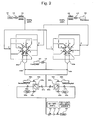
- FIG. 2 is a view illustrating an embodiment of an apparatus for synthesizing acrolein, used in the present invention.
- water is delivered at 35 MPa with a supercritical water high pressure pump (110) and is increased in temperature to 500°C with a supercritical water pre-heater (120).
- a raw material composed of glycerin and diluted sulfuric acid is delivered at 35 MPa with a raw material high pressure pump (210) and is increased in temperature to 250°C with a raw material pre-heater (220).
- the water and the raw material are mixed with each other with reaction apparatuses (300a, 300b) utilizing swirl flow, and thus instantly the synthesis reaction of acrolein is started at 400°C and 35 MPa.
- FIG. 3 shows an oblique perspective view of a reaction apparatus utilizing swirl flow in the present invention
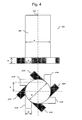
- FIG. 4 shows a front view and a plan view of the reaction apparatus shown in FIG. 3
- the end of a cylindrical mixing flow path (320) is hermetically sealed, and first inlet flow paths (310X) for introducing a fluid containing glycerin into the mixing flow path (320) and second inlet flow paths (310Y) for introducing a fluid containing supercritical water into the mixing flow path (320) are connected to the hermetically sealed end.
- the first inlet flow paths (310X) and the second inlet flow paths (310Y) are each connected to the mixing flow path (320) in a condition of being offset by ⁇ in relation to the central axis of the mixing flow path (320). With this structure, a swirl flow can be generated in the mixing flow path (320) and thus the miscibility can be improved.
- first inlet flow paths (310X) and the second inlet flow paths (310Y) are connected in such a way that the total number of the inlet flow paths is eight, and the first and second inlet flow paths are alternately arranged so as to encircle the central axis of the mixing flow path (320) with a constant angular interval of 45°.
- a plurality of the first inlet flow paths (310X) and a plurality of the second inlet flow paths (310Y) are connected to the mixing flow path (320), hence a multiple layer flow can be formed in the mixing flow path (320), the diffusion distance is reduced as compared to the conventional two layer flow, and the miscibility can be improved.
- the first inlet flow paths (310X) and the second inlet flow paths (310Y) are connected at right angle to the central axis of the mixing flow path (320); however, the connection angle is not limited to this angle.
- the connection angle is not limited to this angle.
- the cross sections of the first and second inlet flow paths (310X, 310Y) are depicted so as to be rectangles, but the first and second inlet flow paths (310X, 310Y) may have other shapes such as cylinders.
- the mixing flow path (320) is also assumed to have a cylindrical shape, and the cylindrical shape as referred to herein includes the shapes each having a polygonal cross section to be approximated as a circle.
- the flow rate Q X of the raw material high pressure pump (210) and the flow rate Q Y of the supercritical water high pressure pump (110) are preferably equal to each other.
- the miscibility can be improved by making the dimension of the first inlet flow paths (310X) and the dimension of the second inlet flow paths (310Y) different from each other in such a way that the flow speed in the first inlet flow paths (310X) and the flow speed in the second inlet flow paths (310Y) are equal to each other.
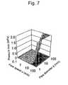
- FIGS. 6 , 7 and 8 show the effects of the inner diameter ⁇ of the mixing pipe and the flow speed u on the mixing time and the pressure loss in the mixing pipe and on the number N of the numbering up of the mixing pipe, in a case where the amount of production of acrolein is about 100,000 t/y.
- the mixing time is required to be set at 0.2 second or less.
- the pressure loss and the number of the numbering up are required to be set at 1 MPa or less and 30 or less, respectively.
- the inner diameter of the mixing pipe is 10 to 50 mm
- the flow speed is 2 to 20 m/s
- the number of the numbering up is 10 to 50.
- the inner diameter of the mixing pipe is about 20 mm
- the flow speed is about 10 m/s
- the number of the numbering up is about 30.
- the material of the reaction apparatus of the present embodiment is preferably Ni-base alloys, having corrosion resistance equal to or higher than the corrosion resistance of SUS 316L, such as Inconel 625 and Hastelloy C-276.
- the fluid containing supercritical water and the fluid containing glycerin are made to form multiple layers and the diffusion distance can be reduced, and by delivering the solutions with the aid of turbulent flow to increase the turbulent flow diffusion coefficient, the swirl flow can be generated in the mixing flow path; therefore, as a result of the combination of these facts, the miscibility can be drastically improved.
- the reaction yield is improved and the amounts of generated tar and the generated by-products can be reduced. Accordingly, the occlusion of the pipes and valves due to the adhesion of the by-products can be prevented. Further, the abrasion of the valving elements and the valve seats are suppressed, and hence the precise pressure control can be performed. Therefore, highly efficient operation of the commercial plant is made possible.
- cooling water is delivered to the junction (420a, 420b) for the purpose of terminating the reaction by using the cooling water high pressure pump (410) shown in FIG. 2 , and the reaction is terminated by direct mixing of the cooling water.
- the optimal reaction time is a few seconds when the glycerin concentration is set at 15%
- the reaction solution is required to be rapidly cooled to the reaction termination temperature in a time of about one-tenth the optimal reaction time.
- the adoption of the direct mixing of cooling water improves the controllability of the reaction time as compared to the indirect cooling with a double pipe cooler.
- the controllability of the reaction time is further improved and the reaction yield can be enhanced.
- the reaction solution is subjected to the separation of tar and carbon particles with the filters (520a, 520b) in the subsequent stage in such a way that only the carbon particles are captured with the filters and the tar is allowed to pass while keeping the high viscosity thereof. Accordingly, the occlusion of the pipes due to the mutual aggregation of tar and carbon particles is prevented.
- reaction solution from which carbon particles have been removed is cooled in a second cooler (620), then decreased in pressure down to the atmospheric pressure with an orifice (630) and a pressure regulation valve (640) and is delivered to a distillation apparatus for acrolein in the subsequent stage.
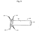
- FIG. 9 shows an oblique perspective view of an embodiment of the reaction apparatus utilizing swirl flow in the present invention
- FIG. 10 shows a front view and a plan view of the reaction apparatus.
- the first inlet flow paths (310X) and the second inlet flow paths (310Y) are connected in such a way that the total number of the inlet flow paths is four, and the first and second inlet flow paths are alternately arranged so as to encircle the central axis of the mixing flow path (320) with a constant angular interval of 90°.
- the total number of the first inlet flow paths (310X) and the second inlet flow paths (310Y) may also be six.
- the miscibility can be improved as compared to conventional T-shaped pipes and conventional reaction apparatuses having two inlet flow paths and utilizing swirl flow.
- FIG. 11 shows an oblique perspective view of an embodiment of the reaction apparatus utilizing swirl flow in the present invention
- FIG. 12 shows a front view and a plan view of the reaction apparatus.
- the end of the cylindrical mixing flow path (320) is hermetically sealed, and the first inlet flow paths (310X) for introducing a fluid containing glycerin into the mixing flow path (320) and the second inlet flow paths (310Y) for introducing a fluid containing supercritical water into the mixing flow path (320) are connected to the hermetically sealed end.
- the first inlet flow paths (310X) and the second inlet flow paths (310Y) are each connected to the mixing flow path (320) in a condition of being offset by ⁇ in relation to the central axis of the mixing flow path (320). Additionally, the first inlet flow path (310X) and the second inlet flow path (310Y) are each provided in a plurality of numbers so as to be separated away from each other along the flow direction of the mixing flow path (320). Because the first inlet flow path and the second inlet flow path are each provided in a plurality of numbers so as to be separated away from each other along the flow direction, the swirl flow layer of the subsequent stage is generated outside the swirl flow layer of the preceding stage. Therefore, as shown in the Z-Z' cross section ( FIG.
- the miscibility can be enhanced, as described above, by determining the cross sectional area (W x H) of the first inlet flow path and the cross sectional area (W x H) of the second inlet flow path in such a way that the flow speed of the first inlet flow path and the flow speed of the second inlet flow path are equal to each other.
- the total number of the first and second inlet flow paths at each stage is set at 2; however, by increasing this total number to 4, 6 or 8, the miscibility can be further improved.
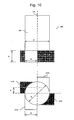
- FIG. 14 shows an embodiment of the reaction apparatus utilizing swirl flow in the present invention.
- a conical portion low in miscibility is generated on the central axis of the mixing flow path (320).
- the miscibility can be improved by disposing a structure (325) in the low miscibility portion. Additionally, by the presence of a structure in the central portion of FIG. 13 , the interlayer distances are further reduced, and hence the miscibility can be improved.
- the structure disposed on the central axis of the mixing flow path is preferably formed so as to be made thinner (so as for the cross sectional area of the structure to be made smaller) as going toward the downstream of the mixing flow path.
- the use of the structure in the reaction apparatuses utilizing swirl flow of the other embodiments can also improve the miscibility.
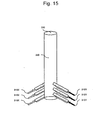
- FIG. 15 shows another embodiment of the reaction apparatus utilizing swirl flow in the present invention.
- the throughput as well as the reaction yield is required to be increased.
- the first and second inlet flow paths (310X, 310Y) are connected so as to make an angle of less than 90° relative to the central axis of the mixing flow path (320), and hence the pressure loss can be reduced and the amount of production can be increased.
- FIG. 16 shows an embodiment of the reaction apparatus using a static mixer in the present invention.
- the first inlet flow path (310X) for making a fluid containing glycerin flow into the mixing flow path (320) and the second inlet flow path (310Y) for making a fluid containing supercritical water flow into the mixing flow path (320) are connected to the end of the cylindrical mixing flow path (320).
- the mixing flow path (320) is equipped with a static mixer (326). The raw material and the supercritical water made to flow into the mixing flow path (320) are agitated with the static mixer (326) and the interlayer distances are further reduced and hence the miscibility is improved.
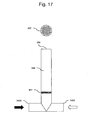
- FIG. 17 shows an embodiment of the reaction apparatus using a perforated plate in the present invention.
- the first inlet flow path (310X) for making a fluid containing glycerin flow into the mixing flow path (320) and the second inlet flow path (310Y) for making a fluid containing supercritical water flow into the mixing flow path (320) are connected to the end of the cylindrical mixing flow path (320) in the same manner as in the sixth embodiment.
- the mixing flow path (320) is equipped with a perforated plate (327).
- the raw material and the supercritical water made to flow into the mixing flow path (320) are made to pass through the perforated plate (327) to be enhanced in miscibility.
- the perforated plate (327) may be provided in a plurality of numbers along the mixing flow path (320). In such a case, the perforation rates of the perforated plates may be set at different values from one perforated plate to another.
Landscapes
- Chemical & Material Sciences (AREA)
- Organic Chemistry (AREA)
- Chemical Kinetics & Catalysis (AREA)
- Dispersion Chemistry (AREA)
- Organic Low-Molecular-Weight Compounds And Preparation Thereof (AREA)
- Low-Molecular Organic Synthesis Reactions Using Catalysts (AREA)
Claims (9)
- Verfahren zum Synthetisieren von Acrolein, indem zugelassen wird, dass überkritisches Wasser mit einem Glycerin enthaltenden Ausgangsmaterial wechselwirkt, wobei das Verfahren einen Reaktionsapparat verwendet, der folgendes umfasst:einen zylindrischen Mischfließweg zum Mischen eines das Ausgangsmaterial enthaltenden Fluids mit einem überkritisches Wasser enthaltenden Fluid;ein erster Einlassfließweg, der versetzt von der Zentralachse des Mischfließwegs angeordnet ist, um zuzulassen, dass das das Ausgangsmaterial enthaltende Fluid in den Mischfließweg fließt; undein zweiter Einlassfließweg, der versetzt von der Zentralachse des Mischfließwegs angeordnet ist, um zuzulassen, dass das das überkritische Wasser enthaltende Fluid in den Mischfließweg fließt,wobei der erste Einlassfließweg und der zweite Einlassfließweg jeweils in einer Vielzahl auf eine Weise vorhanden sind, dass die ersten Einlassfließwege und die zweiten Einlassfließwege abwechselnd angeordnet sind, um die Zentralachse des Mischfließwegs zu umgeben.
- Verfahren nach Anspruch 1 zum Synthetisieren von Acrolein, indem zugelassen wird, dass überkritisches Wasser und eine Säure mit Glycerin als Ausgangsmaterial wechselwirken, wobei ein Glycerin enthaltendes Fluid mit einem das überkritische Wasser enthaltenden Fluid gemischt wird.
- Verfahren zum Synthetisieren von Acrolein, indem zugelassen wird, dass überkritisches Wasser und eine Säure mit Glycerin wechselwirken, wobei das Verfahren einen Reaktionsapparat verwendet, der folgendes umfasst:einen zylindrischen Mischfließweg zum Mischen eines Glycerin enthaltenden Fluids mit einem überkritisches Wasser enthaltenden Fluid;einen ersten Einlassfließweg, der versetzt von der Zentralachse des Mischfließwegs angeordnet ist, um zuzulassen, dass das Glycerin enthaltende Fluid in dem Mischfließweg fließt, undeinen zweiten Einlassfließweg, der versetzt von der Zentralachse des Mischfließwegs angeordnet ist, um zuzulassen, dass das überkritische Wasser enthaltende Fluid in den Mischfließweg fließt,wobei der erste Einlassfließweg und der zweite Einlassfließweg jeweils in einer Vielzahl entlang der Fließrichtung des Mischfließwegs vorhanden sind, so dass sie voneinander abgetrennt sind.
- Verfahren nach einem der vorstehenden Ansprüche, wobei die Struktur auf der Zentralachse des Mischfließwegs angeordnet ist.
- Verfahren nach Anspruch 4, wobei die Struktur auf der Zentralachse des Mischfließwegs auf eine solche Weise gebildet ist, dass die Querschnittsfläche der Struktur stromabwärts des Mischfließwegs geringer wird.
- Verfahren nach einem der vorstehenden Ansprüche, wobei zwischen der Fließrate QX und der Querschnittsfläche SX pro Weg der ersten Einlassfließwege und die Fließrate QY und die Querschnittsfläche SY pro Weg der zweiten Einlassfließwege die folgende Beziehung besteht:

- Verfahren nach einem der vorstehenden Ansprüche, wobei die Synthese durchgeführt wird, indem eine Vielzahl der Reaktionsapparate in Kombination angeordnet wird.
- Verfahren zum Synthetisieren von Acrolein, indem zugelassen wird, dass überkritisches Wasser und eine Säure mit Glycerin wechselwirken, wobei das Verfahren einen Reaktionsapparat verwendet, der folgendes umfasst:einen zylindrischen Mischfließweg, um ein Glycerin enthaltendes Fluid und ein überkritisches Wasser enthaltendes Fluid miteinander zu mischen;
einen ersten Einlassfließweg, der mit dem Mischfließweg verbunden ist, um zuzulassen, dass das Glycerin enthaltende Fluid in den Mischfließweg fließt, und
einen zweiten Einlassfließweg, der mit dem Mischfließweg verbunden ist, um zuzulassen, dass das überkritische Wasser enthaltende Fluid in den Mischfließweg fließt,
wobei ein statischer Mischer oder eine perforierte Platte in dem Mischfließweg angeordnet ist. - Verfahren nach einem der vorstehenden Ansprüche, wobei die Anzahl der ersten Einlassfließwege vier ist und die Anzahl der zweiten Einlassfließwege vier ist.
Applications Claiming Priority (1)
| Application Number | Priority Date | Filing Date | Title |
|---|---|---|---|
| JP2009297832A JP5706611B2 (ja) | 2009-12-28 | 2009-12-28 | アクロレインの合成方法 |
Publications (2)
| Publication Number | Publication Date |
|---|---|
| EP2338869A1 EP2338869A1 (de) | 2011-06-29 |
| EP2338869B1 true EP2338869B1 (de) | 2013-09-11 |
Family
ID=43735947
Family Applications (1)
| Application Number | Title | Priority Date | Filing Date |
|---|---|---|---|
| EP10016149.6A Not-in-force EP2338869B1 (de) | 2009-12-28 | 2010-12-28 | Verfahren zur Synthetisierung von Acrolein |
Country Status (5)
| Country | Link |
|---|---|
| US (1) | US8450531B2 (de) |
| EP (1) | EP2338869B1 (de) |
| JP (1) | JP5706611B2 (de) |
| CN (1) | CN102126937A (de) |
| BR (1) | BRPI1005470A2 (de) |
Families Citing this family (2)
| Publication number | Priority date | Publication date | Assignee | Title |
|---|---|---|---|---|
| JP2013248554A (ja) * | 2012-05-31 | 2013-12-12 | Hitachi Ltd | 超臨界水もしくは亜臨界水を用いた反応装置および方法 |
| CN113207394B (zh) * | 2021-05-11 | 2022-05-24 | 湖南栀葆堂中药科技有限公司 | 一种中药材种植用精准施肥机及中药材种植方法 |
Family Cites Families (14)
| Publication number | Priority date | Publication date | Assignee | Title |
|---|---|---|---|---|
| DE19703383A1 (de) | 1997-01-30 | 1998-08-06 | Degussa | Verfahren zur Herstellung von 1,3-Propandiol |
| JP3655482B2 (ja) * | 1999-02-25 | 2005-06-02 | バブコック日立株式会社 | 流体混合器 |
| JP4330839B2 (ja) * | 2002-01-18 | 2009-09-16 | 旭化成ケミカルズ株式会社 | グルコース及び/又は水溶性セロオリゴ糖の製造方法 |
| JP3939556B2 (ja) * | 2002-01-18 | 2007-07-04 | 富士フイルム株式会社 | マイクロミキサー |
| JP4407177B2 (ja) * | 2003-05-30 | 2010-02-03 | 富士フイルム株式会社 | マイクロリアクターを用いた反応方法 |
| JP2006167600A (ja) * | 2004-12-16 | 2006-06-29 | Nikkiso Co Ltd | マイクロミキサー、マイクロミキサーチップおよびマイクロセンサー |
| JP2006255552A (ja) * | 2005-03-16 | 2006-09-28 | Daio Paper Corp | 流体混合装置及び漂白パルプの製造方法 |
| DE102005015433A1 (de) * | 2005-04-05 | 2006-10-12 | Forschungszentrum Karlsruhe Gmbh | Mischersystem, Reaktor und Reaktorsystem |
| JP4840916B2 (ja) | 2006-07-06 | 2011-12-21 | 独立行政法人産業技術総合研究所 | 高温高圧マイクロミキサー |
| JP2009132663A (ja) * | 2007-11-30 | 2009-06-18 | National Institute Of Advanced Industrial & Technology | アクロレイン類の製造法とその装置 |
| JP2009241001A (ja) * | 2008-03-31 | 2009-10-22 | Okayama Prefecture Industrial Promotion Foundation | マイクロミキサ |
| JP4687754B2 (ja) | 2008-07-01 | 2011-05-25 | 株式会社日立プラントテクノロジー | 超臨界水を用いたアクロレインの製造方法 |
| JP5604038B2 (ja) | 2008-08-25 | 2014-10-08 | 株式会社日立製作所 | 反応装置及び反応プラント |
| JP5304299B2 (ja) | 2009-02-12 | 2013-10-02 | 株式会社日立プラントテクノロジー | 臨界水を用いた反応プロセス |
-
2009
- 2009-12-28 JP JP2009297832A patent/JP5706611B2/ja not_active Expired - Fee Related
-
2010
- 2010-12-28 BR BRPI1005470-7A patent/BRPI1005470A2/pt not_active IP Right Cessation
- 2010-12-28 US US12/979,459 patent/US8450531B2/en not_active Expired - Fee Related
- 2010-12-28 EP EP10016149.6A patent/EP2338869B1/de not_active Not-in-force
- 2010-12-28 CN CN201010621643XA patent/CN102126937A/zh active Pending
Also Published As
| Publication number | Publication date |
|---|---|
| BRPI1005470A2 (pt) | 2013-04-16 |
| JP5706611B2 (ja) | 2015-04-22 |
| CN102126937A (zh) | 2011-07-20 |
| US8450531B2 (en) | 2013-05-28 |
| EP2338869A1 (de) | 2011-06-29 |
| JP2011136943A (ja) | 2011-07-14 |
| US20110160447A1 (en) | 2011-06-30 |
Similar Documents
| Publication | Publication Date | Title |
|---|---|---|
| EP2318129B1 (de) | Parallelisierte strahlschlaufenreaktoren | |
| KR100755886B1 (ko) | 미세반응기에서 디스아조 축합 안료의 제조방법 | |
| CN111592466B (zh) | 一种左卡尼汀的微反应连续流合成方法 | |
| CN108863760B (zh) | 一种利用微通道反应器连续化生产乙醛酸的方法 | |
| CN113563201B (zh) | 基于固定床微反应器连续高效合成3,4-二氯苯胺的方法 | |
| CN107879337B (zh) | 制备氧化石墨烯的方法及其设备 | |
| CN102241558B (zh) | 一种苯选择性加氢制备环己烯反应装置及工艺 | |
| CN113967454A (zh) | 一种高选择性连续合成混二硝基苯的装置及方法 | |
| CN113773181A (zh) | 一种1,3-二氯丙酮的连续流制备方法及微反应系统 | |
| EP2338869A1 (de) | Verfahren zur Synthetisierung von Acrolein | |
| CN111253284B (zh) | 一种全过程连续化的苯乙腈生产装置及工艺 | |
| CN1326605C (zh) | 一种多通道微结构反应器 | |
| CN214937128U (zh) | 液液非均相连续反应系统 | |
| CN112430188B (zh) | 一种新型加氢技术制备异丙基苯胺的方法 | |
| CN111454156B (zh) | 一种连续合成4-乙基硝基苯和2-乙基硝基苯的方法 | |
| CN110841585A (zh) | 一种苯乙腈生产装置及其使用方法 | |
| CN106905189B (zh) | 用于乙二醇双(丙腈)醚合成的微反应器系统和方法 | |
| CN116023237B (zh) | 一种水相中对苯二酚的连续化制备方法 | |
| EP2049245A1 (de) | Anlage und verfahren zur kontinuierlichen industriellen herstellung von 3-glycidyloxypropylalkoxysilanen | |
| CN114432980B (zh) | 一种微通道反应装置及其应用 | |
| CN109438175B (zh) | 一种环己基过氧化氢分解制备环己醇和环己酮的方法 | |
| CN210206780U (zh) | 一种连续流综合实验撬装装置 | |
| CN116672981A (zh) | 一种基于分形谢尔宾斯基三角形结构的微反应器及其用途和气液烯烃氢甲酰化反应的方法 | |
| EP2151274B1 (de) | Öffnungsstrahl-Injektionsreaktor | |
| CN213708197U (zh) | 一种对氯苯肼盐酸盐反应系统 |
Legal Events
| Date | Code | Title | Description |
|---|---|---|---|
| PUAI | Public reference made under article 153(3) epc to a published international application that has entered the european phase |
Free format text: ORIGINAL CODE: 0009012 |
|
| AK | Designated contracting states |
Kind code of ref document: A1 Designated state(s): AL AT BE BG CH CY CZ DE DK EE ES FI FR GB GR HR HU IE IS IT LI LT LU LV MC MK MT NL NO PL PT RO RS SE SI SK SM TR |
|
| AX | Request for extension of the european patent |
Extension state: BA ME |
|
| 17P | Request for examination filed |
Effective date: 20111227 |
|
| 17Q | First examination report despatched |
Effective date: 20120301 |
|
| GRAP | Despatch of communication of intention to grant a patent |
Free format text: ORIGINAL CODE: EPIDOSNIGR1 |
|
| GRAS | Grant fee paid |
Free format text: ORIGINAL CODE: EPIDOSNIGR3 |
|
| GRAA | (expected) grant |
Free format text: ORIGINAL CODE: 0009210 |
|
| AK | Designated contracting states |
Kind code of ref document: B1 Designated state(s): AL AT BE BG CH CY CZ DE DK EE ES FI FR GB GR HR HU IE IS IT LI LT LU LV MC MK MT NL NO PL PT RO RS SE SI SK SM TR |
|
| REG | Reference to a national code |
Ref country code: GB Ref legal event code: FG4D |
|
| REG | Reference to a national code |
Ref country code: CH Ref legal event code: EP |
|
| REG | Reference to a national code |
Ref country code: AT Ref legal event code: REF Ref document number: 631526 Country of ref document: AT Kind code of ref document: T Effective date: 20130915 |
|
| REG | Reference to a national code |
Ref country code: IE Ref legal event code: FG4D |
|
| REG | Reference to a national code |
Ref country code: DE Ref legal event code: R096 Ref document number: 602010010140 Country of ref document: DE Effective date: 20131107 |
|
| PG25 | Lapsed in a contracting state [announced via postgrant information from national office to epo] |
Ref country code: HR Free format text: LAPSE BECAUSE OF FAILURE TO SUBMIT A TRANSLATION OF THE DESCRIPTION OR TO PAY THE FEE WITHIN THE PRESCRIBED TIME-LIMIT Effective date: 20130911 Ref country code: LT Free format text: LAPSE BECAUSE OF FAILURE TO SUBMIT A TRANSLATION OF THE DESCRIPTION OR TO PAY THE FEE WITHIN THE PRESCRIBED TIME-LIMIT Effective date: 20130911 Ref country code: SE Free format text: LAPSE BECAUSE OF FAILURE TO SUBMIT A TRANSLATION OF THE DESCRIPTION OR TO PAY THE FEE WITHIN THE PRESCRIBED TIME-LIMIT Effective date: 20130911 Ref country code: NO Free format text: LAPSE BECAUSE OF FAILURE TO SUBMIT A TRANSLATION OF THE DESCRIPTION OR TO PAY THE FEE WITHIN THE PRESCRIBED TIME-LIMIT Effective date: 20131211 Ref country code: CY Free format text: LAPSE BECAUSE OF FAILURE TO SUBMIT A TRANSLATION OF THE DESCRIPTION OR TO PAY THE FEE WITHIN THE PRESCRIBED TIME-LIMIT Effective date: 20130724 |
|
| REG | Reference to a national code |
Ref country code: NL Ref legal event code: VDEP Effective date: 20130911 |
|
| REG | Reference to a national code |
Ref country code: AT Ref legal event code: MK05 Ref document number: 631526 Country of ref document: AT Kind code of ref document: T Effective date: 20130911 |
|
| REG | Reference to a national code |
Ref country code: DE Ref legal event code: R082 Ref document number: 602010010140 Country of ref document: DE Representative=s name: PATENTANWAELTE STREHL, SCHUEBEL-HOPF & PARTNER, DE |
|
| REG | Reference to a national code |
Ref country code: LT Ref legal event code: MG4D |
|
| PG25 | Lapsed in a contracting state [announced via postgrant information from national office to epo] |
Ref country code: FI Free format text: LAPSE BECAUSE OF FAILURE TO SUBMIT A TRANSLATION OF THE DESCRIPTION OR TO PAY THE FEE WITHIN THE PRESCRIBED TIME-LIMIT Effective date: 20130911 Ref country code: LV Free format text: LAPSE BECAUSE OF FAILURE TO SUBMIT A TRANSLATION OF THE DESCRIPTION OR TO PAY THE FEE WITHIN THE PRESCRIBED TIME-LIMIT Effective date: 20130911 Ref country code: GR Free format text: LAPSE BECAUSE OF FAILURE TO SUBMIT A TRANSLATION OF THE DESCRIPTION OR TO PAY THE FEE WITHIN THE PRESCRIBED TIME-LIMIT Effective date: 20131212 Ref country code: SI Free format text: LAPSE BECAUSE OF FAILURE TO SUBMIT A TRANSLATION OF THE DESCRIPTION OR TO PAY THE FEE WITHIN THE PRESCRIBED TIME-LIMIT Effective date: 20130911 |
|
| REG | Reference to a national code |
Ref country code: DE Ref legal event code: R082 Ref document number: 602010010140 Country of ref document: DE Representative=s name: STREHL SCHUEBEL-HOPF & PARTNER MBB PATENTANWAE, DE Effective date: 20140218 Ref country code: DE Ref legal event code: R081 Ref document number: 602010010140 Country of ref document: DE Owner name: HITACHI, LTD., JP Free format text: FORMER OWNER: HITACHI PLANT TECHNOLOGIES, LTD., TOKYO, JP Effective date: 20140218 Ref country code: DE Ref legal event code: R082 Ref document number: 602010010140 Country of ref document: DE Representative=s name: PATENTANWAELTE STREHL, SCHUEBEL-HOPF & PARTNER, DE Effective date: 20140218 |
|
| PG25 | Lapsed in a contracting state [announced via postgrant information from national office to epo] |
Ref country code: BE Free format text: LAPSE BECAUSE OF FAILURE TO SUBMIT A TRANSLATION OF THE DESCRIPTION OR TO PAY THE FEE WITHIN THE PRESCRIBED TIME-LIMIT Effective date: 20130911 Ref country code: CY Free format text: LAPSE BECAUSE OF FAILURE TO SUBMIT A TRANSLATION OF THE DESCRIPTION OR TO PAY THE FEE WITHIN THE PRESCRIBED TIME-LIMIT Effective date: 20130911 |
|
| PG25 | Lapsed in a contracting state [announced via postgrant information from national office to epo] |
Ref country code: IS Free format text: LAPSE BECAUSE OF FAILURE TO SUBMIT A TRANSLATION OF THE DESCRIPTION OR TO PAY THE FEE WITHIN THE PRESCRIBED TIME-LIMIT Effective date: 20140111 Ref country code: CZ Free format text: LAPSE BECAUSE OF FAILURE TO SUBMIT A TRANSLATION OF THE DESCRIPTION OR TO PAY THE FEE WITHIN THE PRESCRIBED TIME-LIMIT Effective date: 20130911 Ref country code: RO Free format text: LAPSE BECAUSE OF FAILURE TO SUBMIT A TRANSLATION OF THE DESCRIPTION OR TO PAY THE FEE WITHIN THE PRESCRIBED TIME-LIMIT Effective date: 20130911 Ref country code: SK Free format text: LAPSE BECAUSE OF FAILURE TO SUBMIT A TRANSLATION OF THE DESCRIPTION OR TO PAY THE FEE WITHIN THE PRESCRIBED TIME-LIMIT Effective date: 20130911 Ref country code: NL Free format text: LAPSE BECAUSE OF FAILURE TO SUBMIT A TRANSLATION OF THE DESCRIPTION OR TO PAY THE FEE WITHIN THE PRESCRIBED TIME-LIMIT Effective date: 20130911 Ref country code: EE Free format text: LAPSE BECAUSE OF FAILURE TO SUBMIT A TRANSLATION OF THE DESCRIPTION OR TO PAY THE FEE WITHIN THE PRESCRIBED TIME-LIMIT Effective date: 20130911 |
|
| PG25 | Lapsed in a contracting state [announced via postgrant information from national office to epo] |
Ref country code: AT Free format text: LAPSE BECAUSE OF FAILURE TO SUBMIT A TRANSLATION OF THE DESCRIPTION OR TO PAY THE FEE WITHIN THE PRESCRIBED TIME-LIMIT Effective date: 20130911 Ref country code: ES Free format text: LAPSE BECAUSE OF FAILURE TO SUBMIT A TRANSLATION OF THE DESCRIPTION OR TO PAY THE FEE WITHIN THE PRESCRIBED TIME-LIMIT Effective date: 20130911 Ref country code: PL Free format text: LAPSE BECAUSE OF FAILURE TO SUBMIT A TRANSLATION OF THE DESCRIPTION OR TO PAY THE FEE WITHIN THE PRESCRIBED TIME-LIMIT Effective date: 20130911 |
|
| REG | Reference to a national code |
Ref country code: DE Ref legal event code: R097 Ref document number: 602010010140 Country of ref document: DE |
|
| PG25 | Lapsed in a contracting state [announced via postgrant information from national office to epo] |
Ref country code: PT Free format text: LAPSE BECAUSE OF FAILURE TO SUBMIT A TRANSLATION OF THE DESCRIPTION OR TO PAY THE FEE WITHIN THE PRESCRIBED TIME-LIMIT Effective date: 20140113 |
|
| REG | Reference to a national code |
Ref country code: FR Ref legal event code: TP Owner name: HITACHI PLANT TECHNOLOGIES, LTD., JP Effective date: 20140612 |
|
| PLBE | No opposition filed within time limit |
Free format text: ORIGINAL CODE: 0009261 |
|
| STAA | Information on the status of an ep patent application or granted ep patent |
Free format text: STATUS: NO OPPOSITION FILED WITHIN TIME LIMIT |
|
| 26N | No opposition filed |
Effective date: 20140612 |
|
| PG25 | Lapsed in a contracting state [announced via postgrant information from national office to epo] |
Ref country code: IT Free format text: LAPSE BECAUSE OF FAILURE TO SUBMIT A TRANSLATION OF THE DESCRIPTION OR TO PAY THE FEE WITHIN THE PRESCRIBED TIME-LIMIT Effective date: 20130911 Ref country code: LU Free format text: LAPSE BECAUSE OF FAILURE TO SUBMIT A TRANSLATION OF THE DESCRIPTION OR TO PAY THE FEE WITHIN THE PRESCRIBED TIME-LIMIT Effective date: 20131228 Ref country code: MC Free format text: LAPSE BECAUSE OF FAILURE TO SUBMIT A TRANSLATION OF THE DESCRIPTION OR TO PAY THE FEE WITHIN THE PRESCRIBED TIME-LIMIT Effective date: 20130911 |
|
| REG | Reference to a national code |
Ref country code: IE Ref legal event code: MM4A |
|
| REG | Reference to a national code |
Ref country code: DE Ref legal event code: R097 Ref document number: 602010010140 Country of ref document: DE Effective date: 20140612 |
|
| PG25 | Lapsed in a contracting state [announced via postgrant information from national office to epo] |
Ref country code: DK Free format text: LAPSE BECAUSE OF FAILURE TO SUBMIT A TRANSLATION OF THE DESCRIPTION OR TO PAY THE FEE WITHIN THE PRESCRIBED TIME-LIMIT Effective date: 20130911 |
|
| PG25 | Lapsed in a contracting state [announced via postgrant information from national office to epo] |
Ref country code: IE Free format text: LAPSE BECAUSE OF NON-PAYMENT OF DUE FEES Effective date: 20131228 |
|
| PG25 | Lapsed in a contracting state [announced via postgrant information from national office to epo] |
Ref country code: SM Free format text: LAPSE BECAUSE OF FAILURE TO SUBMIT A TRANSLATION OF THE DESCRIPTION OR TO PAY THE FEE WITHIN THE PRESCRIBED TIME-LIMIT Effective date: 20130911 |
|
| PG25 | Lapsed in a contracting state [announced via postgrant information from national office to epo] |
Ref country code: TR Free format text: LAPSE BECAUSE OF FAILURE TO SUBMIT A TRANSLATION OF THE DESCRIPTION OR TO PAY THE FEE WITHIN THE PRESCRIBED TIME-LIMIT Effective date: 20130911 |
|
| PG25 | Lapsed in a contracting state [announced via postgrant information from national office to epo] |
Ref country code: RS Free format text: LAPSE BECAUSE OF FAILURE TO SUBMIT A TRANSLATION OF THE DESCRIPTION OR TO PAY THE FEE WITHIN THE PRESCRIBED TIME-LIMIT Effective date: 20131211 Ref country code: BG Free format text: LAPSE BECAUSE OF FAILURE TO SUBMIT A TRANSLATION OF THE DESCRIPTION OR TO PAY THE FEE WITHIN THE PRESCRIBED TIME-LIMIT Effective date: 20130911 Ref country code: MK Free format text: LAPSE BECAUSE OF FAILURE TO SUBMIT A TRANSLATION OF THE DESCRIPTION OR TO PAY THE FEE WITHIN THE PRESCRIBED TIME-LIMIT Effective date: 20130911 Ref country code: HU Free format text: LAPSE BECAUSE OF FAILURE TO SUBMIT A TRANSLATION OF THE DESCRIPTION OR TO PAY THE FEE WITHIN THE PRESCRIBED TIME-LIMIT; INVALID AB INITIO Effective date: 20101228 |
|
| REG | Reference to a national code |
Ref country code: CH Ref legal event code: PL |
|
| GBPC | Gb: european patent ceased through non-payment of renewal fee |
Effective date: 20141228 |
|
| PG25 | Lapsed in a contracting state [announced via postgrant information from national office to epo] |
Ref country code: MT Free format text: LAPSE BECAUSE OF FAILURE TO SUBMIT A TRANSLATION OF THE DESCRIPTION OR TO PAY THE FEE WITHIN THE PRESCRIBED TIME-LIMIT Effective date: 20130911 |
|
| PG25 | Lapsed in a contracting state [announced via postgrant information from national office to epo] |
Ref country code: CH Free format text: LAPSE BECAUSE OF NON-PAYMENT OF DUE FEES Effective date: 20141231 Ref country code: GB Free format text: LAPSE BECAUSE OF NON-PAYMENT OF DUE FEES Effective date: 20141228 Ref country code: LI Free format text: LAPSE BECAUSE OF NON-PAYMENT OF DUE FEES Effective date: 20141231 |
|
| REG | Reference to a national code |
Ref country code: FR Ref legal event code: PLFP Year of fee payment: 6 |
|
| PGFP | Annual fee paid to national office [announced via postgrant information from national office to epo] |
Ref country code: FR Payment date: 20151110 Year of fee payment: 6 |
|
| PGFP | Annual fee paid to national office [announced via postgrant information from national office to epo] |
Ref country code: DE Payment date: 20151222 Year of fee payment: 6 |
|
| REG | Reference to a national code |
Ref country code: DE Ref legal event code: R119 Ref document number: 602010010140 Country of ref document: DE |
|
| REG | Reference to a national code |
Ref country code: FR Ref legal event code: ST Effective date: 20170831 |
|
| PG25 | Lapsed in a contracting state [announced via postgrant information from national office to epo] |
Ref country code: FR Free format text: LAPSE BECAUSE OF NON-PAYMENT OF DUE FEES Effective date: 20170102 |
|
| PG25 | Lapsed in a contracting state [announced via postgrant information from national office to epo] |
Ref country code: DE Free format text: LAPSE BECAUSE OF NON-PAYMENT OF DUE FEES Effective date: 20170701 |
|
| PG25 | Lapsed in a contracting state [announced via postgrant information from national office to epo] |
Ref country code: AL Free format text: LAPSE BECAUSE OF FAILURE TO SUBMIT A TRANSLATION OF THE DESCRIPTION OR TO PAY THE FEE WITHIN THE PRESCRIBED TIME-LIMIT Effective date: 20130911 |