EP2337637B1 - Centrifugal separator - Google Patents
Centrifugal separator Download PDFInfo
- Publication number
- EP2337637B1 EP2337637B1 EP09788608.9A EP09788608A EP2337637B1 EP 2337637 B1 EP2337637 B1 EP 2337637B1 EP 09788608 A EP09788608 A EP 09788608A EP 2337637 B1 EP2337637 B1 EP 2337637B1
- Authority
- EP
- European Patent Office
- Prior art keywords
- rotating part
- centrifugal separator
- bearing
- receiving element
- separator according
- Prior art date
- Legal status (The legal status is an assumption and is not a legal conclusion. Google has not performed a legal analysis and makes no representation as to the accuracy of the status listed.)
- Active
Links
Images

Classifications
-
- B—PERFORMING OPERATIONS; TRANSPORTING
- B04—CENTRIFUGAL APPARATUS OR MACHINES FOR CARRYING-OUT PHYSICAL OR CHEMICAL PROCESSES
- B04B—CENTRIFUGES
- B04B1/00—Centrifuges with rotary bowls provided with solid jackets for separating predominantly liquid mixtures with or without solid particles
- B04B1/04—Centrifuges with rotary bowls provided with solid jackets for separating predominantly liquid mixtures with or without solid particles with inserted separating walls
-
- B—PERFORMING OPERATIONS; TRANSPORTING
- B04—CENTRIFUGAL APPARATUS OR MACHINES FOR CARRYING-OUT PHYSICAL OR CHEMICAL PROCESSES
- B04B—CENTRIFUGES
- B04B9/00—Drives specially designed for centrifuges; Arrangement or disposition of transmission gearing; Suspending or balancing rotary bowls
- B04B9/02—Electric motor drives
- B04B9/04—Direct drive
-
- B—PERFORMING OPERATIONS; TRANSPORTING
- B04—CENTRIFUGAL APPARATUS OR MACHINES FOR CARRYING-OUT PHYSICAL OR CHEMICAL PROCESSES
- B04B—CENTRIFUGES
- B04B1/00—Centrifuges with rotary bowls provided with solid jackets for separating predominantly liquid mixtures with or without solid particles
- B04B1/04—Centrifuges with rotary bowls provided with solid jackets for separating predominantly liquid mixtures with or without solid particles with inserted separating walls
- B04B1/08—Centrifuges with rotary bowls provided with solid jackets for separating predominantly liquid mixtures with or without solid particles with inserted separating walls of conical shape
-
- B—PERFORMING OPERATIONS; TRANSPORTING
- B04—CENTRIFUGAL APPARATUS OR MACHINES FOR CARRYING-OUT PHYSICAL OR CHEMICAL PROCESSES
- B04B—CENTRIFUGES
- B04B11/00—Feeding, charging, or discharging bowls
- B04B11/02—Continuous feeding or discharging; Control arrangements therefor
-
- B—PERFORMING OPERATIONS; TRANSPORTING
- B04—CENTRIFUGAL APPARATUS OR MACHINES FOR CARRYING-OUT PHYSICAL OR CHEMICAL PROCESSES
- B04B—CENTRIFUGES
- B04B7/00—Elements of centrifuges
- B04B7/08—Rotary bowls
- B04B7/12—Inserts, e.g. armouring plates
-
- B—PERFORMING OPERATIONS; TRANSPORTING
- B04—CENTRIFUGAL APPARATUS OR MACHINES FOR CARRYING-OUT PHYSICAL OR CHEMICAL PROCESSES
- B04B—CENTRIFUGES
- B04B9/00—Drives specially designed for centrifuges; Arrangement or disposition of transmission gearing; Suspending or balancing rotary bowls
- B04B9/08—Arrangement or disposition of transmission gearing ; Couplings; Brakes
-
- B—PERFORMING OPERATIONS; TRANSPORTING
- B04—CENTRIFUGAL APPARATUS OR MACHINES FOR CARRYING-OUT PHYSICAL OR CHEMICAL PROCESSES
- B04B—CENTRIFUGES
- B04B9/00—Drives specially designed for centrifuges; Arrangement or disposition of transmission gearing; Suspending or balancing rotary bowls
- B04B9/12—Suspending rotary bowls ; Bearings; Packings for bearings
Definitions
- the present invention refers to a centrifugal separator according to the preamble of claim 1, see US-5,364,335 .
- SE-C-507 107 discloses a centrifugal separator comprising a stationary part forming a base, non-rotating part, which comprises a bracket and which is elastically connected to the stationary part by means of an elastic connection, and rotating part which is configured to rotate around an axis of rotation and comprises a centrifuge rotor.
- the centrifuge rotor comprises a rotor casing, which forms an inner separation space, and a rotating bearing-receiving element in the form a spindle.
- the centrifuge rotor comprises a disk package with a plurality of separating disks.
- the rotating part is journalled in a stiff manner in the non-rotating part in such a way that the rotating part and the non-rotating part are commonly pivotable in relation to the stationary part by means of the elastic connection.
- a drive arrangement drives the rotating part to rotate around the axis of rotation within a range of revolutions, which extends from zero to a highest number of revolutions per minute and which comprises at least one operating number of revolutions.
- An inlet channel (not disclosed) extends into the inner separation space for feeding of a medium to be separated.
- An outlet channel which is fixedly attached to the stationary part, extends out from the inner separation space for discharge of a separated product.
- WO2007/125066 discloses another similar separator where the stator of the drive motor is fixedly connected to the stationary part.
- centrifugal separators have typically been designed with a relatively long and thin spindle, which permits the centrifuge rotor to pivot or oscillate laterally. All centrifugal separators have a number of critical numbers of revolutions at which such pivoting or lateral deflection, of the centrifuge rotor arises. It is desirable to drive centrifugal separators at relatively high numbers of revolutions for achieving an efficient separation. These desired numbers of revolutions are normally higher than at least the first critical number of revolutions. When initiating a separation process, the first critical number of revolutions thus has to be passed. Stable operation is achieved within a range of revolutions above the first critical number of revolutions.
- Centrifugal separators of a conventional kind also have a limitation with regard to how high the centrifuge rotor and the disk package provided therein can be made.
- This limitation depends at least partly on the relation of the moments of inertia of the centrifuge rotor, i.e. between the polar moment of inertia of the centrifuge rotor and the diametrical moments of inertia of the centrifuge rotor. If this relation of moments of inertia is too small it is difficult to achieve a stable operation. It would be desirable to be able to make the centrifuge rotor higher in spite of the limitation formed by the relation of moments of inertia, since then more separating disks can be provided and the separation capacity can be increased.
- the object of the present invention is to overcome the problems mentioned above. Especially, it is aimed at a centrifugal separator which can be manufactured with a relatively high centrifuge rotor and which can be operated in a stable manner. Furthermore, it is aimed at a construction which in an easy manner can be modified and adapted to centrifuge rotors with different heights.
- centrifugal separator initially defined, which is characterized by the characterizing features of claim 1.
- the tubular bearing-receiving element may have a high stiffness at the same time as an access from one end of the separation space can be achieved.
- the relatively stiff bearing-receiving element in combination with the non-rotating part which thanks to the elastic connection is permitted to pivot with the centrifuge rotor and the bearing-receiving element and form a relatively large co-pivoting mass, permits a stable operation, and in particular a rotor dynamic stable operation, with a relatively high centrifuge rotor and a relatively high disk package.
- the inlet channel is connected in a stiff manner to and comprised by the non-rotating part.
- the inlet channel may extend through the tubular bearing-receiving element. The inlet channel thus forms a part of the co-pivoting mass.
- the outlet channel is connected in a stiff manner to and comprised by the non-rotating part.
- the outlet channel may extend through the tubular bearing-receiving element.
- the outlet channel thus forms a part of the co-pivoting mass.
- inlet and outlet channels comprise or form part of the non-rotating part, which are specifically provided in the bearing-receiving element and stiff per se, or substantially stiff, relative pivoting movements between the rotor casing on the one hand and the inlet and outlet channels on the other hand may be avoided.
- the bearing-receiving element is stiff and configured to maintain a constant straight extension being parallel with the axis of rotation within the whole range of revolutions.
- the disk package has an outer diameter D and the bearing-receiving element an inner diameter d, and wherein d/D is larger than or equal to 0,2.
- the disk package has an outer diameter D and height H, and wherein H/D is larger than or equal to 0,8.
- the rotating part comprises two critical numbers of revolutions, which both derive from said pivotability in a radial direction in relation to the stationary part, and wherein the operating number of revolutions is higher than the two critical numbers of revolutions.
- These conditions include at least some of the following conditions, manly that the rotating part is journalled in a stiff manner in the non-rotating part, that the rotating part can not move axially in relation to the non-rotating part, that the rotating part and the non-rotating part can not oscillate axially in relation to the stationary part, and that the rotating part and the non-rotating part can not turn (torsion oscillation) around the axis of rotation in relation to the stationary part.
- the non-rotating part has a moment of inertia J I with respect to a transversal axis, which extends perpendicular to the axis of rotation and through a common centre of gravity for the rotating part and the non-rotating part, wherein the rotating part has a diametrical moment of inertia J R with respect to the transversal axis and a polar moment of inertia J P with respect to the axis of rotation, and wherein 1,1 * J P is less than J R + J I .
- the non-rotating part has a mass m I
- the rotating part has a mass m R , wherein m I /m R is larger than or equal to 0,1.
- the centrifugal separator comprises a protecting cover which is comprised by the stationary part and which encloses the centrifuge rotor.
- the non-rotating part comprises a carrying element
- the centrifugal separator comprises a bearing arrangement which is comprised by the rotating part and the non-rotating part and which is provided between and connected to the bearing-receiving element and the carrying element, and wherein the carrying element, the bearing arrangement and the bearing-receiving element form a stiff unit.
- the stator may be provided on, and connected in a stiff manner to, the carrying element.
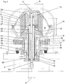
- Fig. 1 discloses a centrifugal separator which comprises or consists of a stationary part, a non-rotating part and a rotating part.
- the stationary part forms a base 4 which is located on a ground, for instance a floor.
- the non-rotating part is elastically connected to the stationary part, i.e. to the base 4, by means of an elastic connection 5.
- the elastic connection 5 may comprise a number of elastic elements, which have elastic and dampening properties, or any form of active damping elements.
- the elastic elements are disposed around the axis x of rotation and, in the embodiments disclosed, in an annular configuration.
- the rotating part is configured to rotate around an axis x of rotation and comprises a centrifuge rotor 6.
- the elastic elements or any other active damping elements are configured in such a way that the rotating part and the non-rotating part may pivot or oscillate in relation to the stationary part and in such a way that the rotating part and the non-rotating part are prevented from oscillating axially or turning around the axis x of rotation, i.e. torsion oscillations are to be prevented.
- the rotating part is journalled in a stiff manner in the non-rotating part in such a way that the rotating part and the non-rotating part are commonly pivotable in relation to the stationary part by means of the elastic connection 5.
- the centrifuge rotor 6 comprises a rotor casing 7 which defines an inner separation space 8.
- the centrifuge rotor 6 also comprises a rotating bearing-receiving element 9.
- the bearing-receiving element 9 forms or corresponds to a spindle of the centrifugal separator.
- the bearing-receiving element 9 thus extends along or in parallel with the axis x of rotation.
- the bearing-receiving element 9 is tubular and forms a passage extending along or in parallel with the axis x of rotation.
- the bearing-receiving element 9 is connected to an upper outwardly projecting, or radially projecting, part 9' to which the rotor casing 7 is connected.
- bearing-receiving element 9 and the outwardly projecting part 9' are designed in one piece. Furthermore, the outwardly projecting part 9' and the rotor casing 7 of the centrifuge rotor 6 are designed as two separate parts which are fixedly connected to each other.
- the non-rotating part comprises a carrying element 10.
- the elastic connection 5, i.e. the elastic elements are provided between the carrying element 10 and the base 4.
- a bearing arrangement comprising one, two or several bearings 11, 11', is provided between and comprised by the rotating part and the non-rotating part.
- the bearing arrangement comprises a first bearing 11 and a second bearing 11', which are provided between and connected to the bearing-receiving element 9 and the carrying element 10.
- the carrying element 10, the bearing arrangement 11, 11' and the bearing-receiving element 9 form a stiff unit where the bearing-receiving element 9 is permitted to rotate in relation to the carrying element 10.
- the centrifugal separator also comprises a protecting cover 12 which is comprised by the stationary part and which encloses or surrounds the centrifuge rotor 6.
- the protecting cover 12 is in the embodiments disclosed attached to the base 4.
- the centrifuge rotor 6 comprises a disk package 13, which comprises a plurality of separating disks 14, a distributor 15 and a distributor support 15'.
- the separating disks 14 may be conical as in the embodiments disclosed or have any other suitable shape for the actual application.
- the disk package 13 rests on the projecting part 9' of the bearing-receiving element 9.
- the disk package 13 and its separating disks 14 are compressed between the projecting part 9' and the rotor casing 7.
- the disk package 13 has an outer diameter D, which corresponds to the outer diameter of each separating disk 14 in a radial direction with regard to the axis x of rotation, and a height H, which extends in parallel with the axis x of rotation from the outer edge of the lowermost separating disk 14 to the outer edge of the uppermost separating disk 14 in the disk package 13.
- the disk package 13 may have a relatively large height in relation to its diameter, which means that H/D can be larger than or equal to 0,8, preferably larger than or equal to 1, more preferably larger than or equal to 1,5. Consequently, the disk package 13 may also in comparison with conventional centrifugal separators have a large height.
- the bearing-receiving element 9 has an inner diameter d of the passage extending in parallel with axis x of rotation.
- the inner diameter d is relatively large, especially in relation to the outer diameter D of the disk package 13, i.e. d/D is larger than or equal to 0,2.
- the centrifugal separator comprises an inlet channel 16, which extends into the inner separation space 8 for feeding of a medium to be separated, and at least one outlet channel 17, which extends out from the inner separation space 8 for discharge of a separated product. It is possible to provide the centrifugal separator with several outlet channels for discharge of different separated products in a manner known per se.
- the centrifugal separator may also comprise openings or nozzles, known per se, for discharge of sludge.
- the inlet channel 16 and the outlet channel 17 are fixedly connected to the carrying part 10.
- the inlet channel 16 and the outlet channel 17 are housed as separate channels in a common pipe 18 extending through the bearing-receiving element 9, i.e. in the above mentioned passage, in parallel with the axis x of rotation, and are fixedly connected to the carrying part 10 via holding element 19.
- the centrifugal separator comprises a drive arrangement for driving the rotating part to rotate around the axis x of rotation within a range of revolutions from zero to a highest number of revolutions per minute, for instance 10 000 revolutions per minute, preferably 12 000 per minute.
- the rotating part is operating at at least an operating number of revolutions which lies within said range of revolutions.
- the drive arrangement comprises an electric motor 20 with a rotor 21, which is comprised by and provided on the rotating part, and a stator 22, which is comprised by the non-rotating part.
- the stator 22 is in the embodiments disclosed provided inside the rotor 21 and on the carrying element 10.
- the rotor 21 is provided on a rotating support member 23, which is rotary symmetric and fixedly connected to, or configured in one piece with the bearing-receiving element 9, and more precisely with, the projecting part 9' forming a part of, or connected to, the bearing-receiving element 9.
- the inlet channel and the outlet channel 17 are per se stiff, or substantially stiff, within the range of revolutions. Furthermore, the inlet channel 16 and the outlet channel 17 are connected to the non-rotating part in a stiff, or substantially stiff, manner in such a way that the inlet channel 16 and the outlet channel 17 are comprised by the non-rotating part.
- This stiff, or substantially stiff, connection is obtained in the embodiments disclosed by means of the common pipe 18 and the holding element 19.
- This stiff, or substantially stiff, connection contributes to the inlet channel 16 and the outlet channel 17 forming a part of the co-pivoting mass, i.e. the may pivot together with the rotating and the non-rotating parts in relation the stationary part.
- the bearing-receiving element 9 is tubular and surrounds or encloses the inlet channel 16 and the outlet channel 17, which thus extend along the axis x of rotation through the bearing-receiving element 9. Both the inlet channel 16 and the outlet channel 17 are thus comprised by the non-rotating part.
- At least one sealing 25, for instance a labyrinth sealing, is provided between the bearing-receiving element 9 and the inlet and outlet channels 16, 17.
- the sealing 25 is provided between the bearing-receiving element 9 and the pipe 18 which encloses the inlet and outlet channels 16, 17. Thanks to the fact that the bearing-receiving element 9 is tubular, this element 9 may be stiff and configured to maintain a constance straight extension which is parallel with the axis x of rotation within the whole range of revolutions.
- the inlet channel 16 comprises a first opening 26, which is located outside the inner separation space 8 and the bearing-receiving element 9, and a second opening 27 which is located in the inner separation space 8.
- the outlet channel 17 comprises a first opening 28, which is located in the inner separation space 8, and a second opening 29, which is located outside the inner separation space 8 and the bearing-receiving element 9.
- the first opening 28 of the outlet channel 17 may be designed as a paring member known per se for discharge of the separated product from the outlet channel 17.
- the rotating part has a mass m R and the non-rotating part has a mass m I .
- the rotating part and the non-rotating part have a common centre of gravity 31.
- the mass relation for the rotating part and the non-rotating part m I /m R is larger than or equal to 0,1.
- a stable operation is achieved within the whole range of revolutions. It is to be noted that the positioning of the masses in relation to each other and the common centre of gravity also is important for achieving a rotor dynamic stable operation.
- the rotating part may comprise a balance ring 33 which is provided on the rotating part and concentric to the axis x of rotation.
- a balance ring 33 is known per se and contributes further to a stable operation of the centrifugal separator.
- the non-rotating part also has a moment of inertia J I with respect to a transversal axis t, which extends perpendicular to the axis x of rotation and through the common centre of gravity 31 for the rotating part and the non-rotating part.
- the rotating part has a diametrical moment of inertia J R with respect to the transversal axis t and a polar moment of inertia Jp with respect to the axis x of rotation.
- the sum of the diametrical moment of inertia J R and the moment of inertia J I is to be larger than the polar moment of inertia J P , and more precisely according to the relation 1,1 * J P is less than J R + J I .
- the rotating part comprises at least two critical numbers of revolutions. These two critical numbers of revolutions derive from the above mentioned pivotability or deflection of the centrifuge rotor in relation to the stationary part.
- the operating number of revolutions is higher than these to critical numbers of revolutions. When the centrifuge rotor is operating at such an operating number of revolutions, a rotor dynamic stable operation is achieved. It is to be noted that there may be several critical numbers of revolutions.
- the rotating part is journalled in a stiff manner in the non-rotating part and may not move axially in relation to the non-rotating part, and where the rotating and non-rotating parts, as a unit or co-pivoting mass, may not oscillate axially or turn around the axis x of rotation, as mentioned above, critical numbers of revolutions, which derive from an axial movement of the rotating part may, however, be eliminated, or substantially eliminated.
- Fig. 2 discloses a second embodiment which differs from the first embodiment in that the drive arrangement comprises an electric motor 20 which is not concentric to the centrifuge rotor but provided laterally with regard to the bearing-receiving element 9.
- the drive arrangement also comprises a power transmission element 40, which in the second embodiment comprises a drive belt.
- the power transmission element may also be realised in other ways, for instance through a gear box.
- the power transmission element 40 is in engagement with a drive wheel 41, which is comprised by and provided on the rotating part, and more precisely on the bearing-receiving element 9, and a drive wheel 42 which is provided on a drive shaft 43 of the electric motor 20.
- the power transmission member 40 is arranged to transmit a drive force from the electric motor 20 and the drive wheel 42 to the drive wheel 41 and the rotating part.
- the electric motor 20 is provided on the carrying element 10 and thus forms a part of the non-rotating part and a part of the co-pivoting mass.
- the drive arrangement may comprise two, three or several motors 20, which via a respective power transmission member 40 acts on the drive wheel 41.
- the drive arrangement can be designed in other ways than disclosed in the two embodiments.
- the rotating part may be driven by means of an electric motor where the drive force is transmitted via a universal coupling.
- the axis of rotation of the electric motor may possibly be concentric to the axis x of rotation.
- hydraulic and/or pneumatic driving may be utilised.
Applications Claiming Priority (2)
| Application Number | Priority Date | Filing Date | Title |
|---|---|---|---|
| SE0802010A SE532905C2 (sv) | 2008-09-22 | 2008-09-22 | Centrifugalseparator |
| PCT/SE2009/051043 WO2010033075A1 (en) | 2008-09-22 | 2009-09-21 | Centrifugal separator |
Publications (2)
| Publication Number | Publication Date |
|---|---|
| EP2337637A1 EP2337637A1 (en) | 2011-06-29 |
| EP2337637B1 true EP2337637B1 (en) | 2018-12-19 |
Family
ID=41432736
Family Applications (1)
| Application Number | Title | Priority Date | Filing Date |
|---|---|---|---|
| EP09788608.9A Active EP2337637B1 (en) | 2008-09-22 | 2009-09-21 | Centrifugal separator |
Country Status (9)
| Country | Link |
|---|---|
| US (2) | US9079193B2 (zh) |
| EP (1) | EP2337637B1 (zh) |
| JP (1) | JP5406300B2 (zh) |
| KR (1) | KR101606226B1 (zh) |
| CN (1) | CN102164680B (zh) |
| BR (1) | BRPI0919313A2 (zh) |
| RU (1) | RU2475309C2 (zh) |
| SE (1) | SE532905C2 (zh) |
| WO (1) | WO2010033075A1 (zh) |
Families Citing this family (14)
| Publication number | Priority date | Publication date | Assignee | Title |
|---|---|---|---|---|
| SE530223C2 (sv) * | 2006-05-15 | 2008-04-01 | Alfa Laval Corp Ab | Centrifugalseparator |
| SE533089C2 (sv) * | 2008-05-13 | 2010-06-22 | Alfa Laval Corp Ab | Centrifugalseparator |
| SE532905C2 (sv) * | 2008-09-22 | 2010-05-04 | Alfa Laval Corp Ab | Centrifugalseparator |
| SE534676C2 (sv) * | 2010-03-22 | 2011-11-15 | Alfa Laval Corp Ab | Centrifugalseparator |
| CN102974474B (zh) * | 2012-11-13 | 2014-02-26 | 湖南航天机电设备与特种材料研究所 | 一种超速离心机 |
| US10272448B1 (en) * | 2016-01-08 | 2019-04-30 | Booker & Dax, Llc | Centrifuge for separating or clarifying food or beverage products |
| DE102017205852B3 (de) | 2017-04-06 | 2018-05-17 | Audi Ag | Tellerseparator |
| DE102017114649A1 (de) | 2017-06-30 | 2019-01-03 | Gea Mechanical Equipment Gmbh | Separator mit Direktantrieb |
| EP3666394A1 (en) * | 2018-12-10 | 2020-06-17 | Alfa Laval Corporate AB | Modular centrifugal separator and base unit thereof and system |
| EP3667063A1 (en) * | 2018-12-13 | 2020-06-17 | Siemens Gamesa Renewable Energy A/S | Device for draining humidity in wind turbines |
| EP3930909A1 (de) * | 2019-02-26 | 2022-01-05 | GEA Mechanical Equipment GmbH | Separator |
| WO2021018540A1 (en) * | 2019-07-26 | 2021-02-04 | Tetra Laval Holdings & Finance S.A. | A centrifugal separator |
| KR102415897B1 (ko) * | 2020-08-13 | 2022-07-05 | 신흥정공(주) | 원심 유수분리기 |
| KR102296235B1 (ko) * | 2021-04-22 | 2021-08-31 | 주식회사 삼공사 | 박형 디스크타입 오일미스트 원심분리기 |
Citations (1)
| Publication number | Priority date | Publication date | Assignee | Title |
|---|---|---|---|---|
| US5364335A (en) * | 1993-12-07 | 1994-11-15 | Dorr-Oliver Incorporated | Disc-decanter centrifuge |
Family Cites Families (29)
| Publication number | Priority date | Publication date | Assignee | Title |
|---|---|---|---|---|
| US1745853A (en) * | 1926-10-16 | 1930-02-04 | Hubert J M C Krantz | Oiling system for centrifugal machines |
| GB425656A (en) * | 1933-05-18 | 1935-03-19 | Separator Ab | Driving mechanism for centrifugal separators |
| US2698131A (en) * | 1951-12-26 | 1954-12-28 | Laval Separator Co De | Centrifugal separator |
| US3187998A (en) * | 1964-03-31 | 1965-06-08 | Vernon D Jarvis | Centrifugal extractor |
| JPS5453772U (zh) * | 1977-09-24 | 1979-04-13 | ||
| US4201066A (en) * | 1978-03-29 | 1980-05-06 | Damon Corporation | Flexible shaft construction for a high inertia centrifuge |
| DE3125832C2 (de) * | 1981-07-01 | 1985-07-25 | Westfalia Separator Ag, 4740 Oelde | Zentrifuge mit einem, mit vertikaler Spindel versehenen Antrieb |
| SU1194504A1 (ru) * | 1982-02-12 | 1985-11-30 | Московский технологический институт мясной и молочной промышленности | Сепаратор дл жидкости |
| SE462077B (sv) | 1986-03-12 | 1990-05-07 | Alfa Laval Separation Ab | Centrifugalseparator med sluten aaterfoering av tungkomponent |
| SU1567280A1 (ru) | 1987-04-14 | 1990-05-30 | Научно-производственное объединение по тракторостроению "НАТИ" | Центрифуга дл очистки масла |
| EP0337286A3 (en) * | 1988-04-11 | 1990-10-31 | E.I. Du Pont De Nemours And Company | Motor mount for a centrifuge |
| DE4314440C1 (de) | 1993-05-03 | 1994-06-16 | Kyffhaeuser Maschf Artern Gmbh | Zentrifugalseparator mit Schwerstanlauf |
| JP3968960B2 (ja) * | 1999-07-15 | 2007-08-29 | 日立工機株式会社 | 遠心機 |
| DE10027958A1 (de) * | 2000-06-08 | 2002-01-10 | Westfalia Separator Food Tec G | Zentrifuge mit Siebanordnung und Verfahren zu deren Betrieb |
| DE10125808A1 (de) | 2001-05-26 | 2002-12-12 | Westfalia Separator Food Tec G | Zentrifugalseparator |
| DE10212808B4 (de) * | 2002-03-22 | 2004-07-29 | Westfalia Separator Ag | Separator |
| RU43198U1 (ru) | 2004-08-06 | 2005-01-10 | Научно-производственное республиканское унитарное предприятие "НПО "Центр" | Привод шнековой центрифуги |
| DE202005001539U1 (de) | 2005-02-01 | 2006-06-14 | Westfalia Separator Ag | Separator mit einem Kurzspindelantrieb |
| DE102006011895A1 (de) | 2006-03-15 | 2007-09-20 | Westfalia Separator Ag | Separatoranordnung in sanitärer Ausführung |
| DE102006020467A1 (de) | 2006-04-28 | 2007-10-31 | Westfalia Separator Ag | Separator mit Direktantrieb |
| SE530223C2 (sv) * | 2006-05-15 | 2008-04-01 | Alfa Laval Corp Ab | Centrifugalseparator |
| SE530024C2 (sv) | 2006-06-20 | 2008-02-12 | Alfa Laval Corp Ab | Centrifugalseparator där den mekaniska tätningsanordningen innefattar ett förspänningselement |
| CN200939404Y (zh) * | 2006-08-22 | 2007-08-29 | 洛阳航峰自动化设备有限公司 | 离心式油液净化机 |
| DE102007060588A1 (de) * | 2007-12-13 | 2009-06-18 | Gea Westfalia Separator Gmbh | Separator mit einem Direktantrieb |
| EP2225042A1 (de) * | 2007-12-13 | 2010-09-08 | GEA Westfalia Separator GmbH | Separator mit einem schmiermittelsystem für einen kurzspindelantrieb |
| SE532905C2 (sv) * | 2008-09-22 | 2010-05-04 | Alfa Laval Corp Ab | Centrifugalseparator |
| SE534676C2 (sv) * | 2010-03-22 | 2011-11-15 | Alfa Laval Corp Ab | Centrifugalseparator |
| EP2567754B1 (en) * | 2011-09-08 | 2018-02-28 | Alfa Laval Corporate AB | A centrifugal separator |
| DE102012110846A1 (de) * | 2012-11-12 | 2014-05-15 | Gea Mechanical Equipment Gmbh | Separator mit Direktantrieb |
-
2008
- 2008-09-22 SE SE0802010A patent/SE532905C2/sv unknown
-
2009
- 2009-09-21 KR KR1020117009114A patent/KR101606226B1/ko active IP Right Grant
- 2009-09-21 CN CN200980138124.3A patent/CN102164680B/zh active Active
- 2009-09-21 BR BRPI0919313A patent/BRPI0919313A2/pt not_active Application Discontinuation
- 2009-09-21 WO PCT/SE2009/051043 patent/WO2010033075A1/en active Application Filing
- 2009-09-21 RU RU2011115812/05A patent/RU2475309C2/ru not_active IP Right Cessation
- 2009-09-21 EP EP09788608.9A patent/EP2337637B1/en active Active
- 2009-09-21 US US13/063,561 patent/US9079193B2/en not_active Expired - Fee Related
- 2009-09-21 JP JP2011527780A patent/JP5406300B2/ja not_active Expired - Fee Related
-
2015
- 2015-06-09 US US14/734,815 patent/US9415400B2/en active Active
Patent Citations (1)
| Publication number | Priority date | Publication date | Assignee | Title |
|---|---|---|---|---|
| US5364335A (en) * | 1993-12-07 | 1994-11-15 | Dorr-Oliver Incorporated | Disc-decanter centrifuge |
Also Published As
| Publication number | Publication date |
|---|---|
| US20150266034A1 (en) | 2015-09-24 |
| CN102164680B (zh) | 2015-12-02 |
| SE0802010A1 (sv) | 2010-03-23 |
| JP2012502790A (ja) | 2012-02-02 |
| KR20110063558A (ko) | 2011-06-10 |
| SE532905C2 (sv) | 2010-05-04 |
| WO2010033075A1 (en) | 2010-03-25 |
| BRPI0919313A2 (pt) | 2015-12-22 |
| JP5406300B2 (ja) | 2014-02-05 |
| US9415400B2 (en) | 2016-08-16 |
| RU2011115812A (ru) | 2012-10-27 |
| RU2475309C2 (ru) | 2013-02-20 |
| KR101606226B1 (ko) | 2016-03-24 |
| CN102164680A (zh) | 2011-08-24 |
| US20110212820A1 (en) | 2011-09-01 |
| EP2337637A1 (en) | 2011-06-29 |
| US9079193B2 (en) | 2015-07-14 |
Similar Documents
| Publication | Publication Date | Title |
|---|---|---|
| EP2337637B1 (en) | Centrifugal separator | |
| EP2282839B1 (en) | Centrifugal separator | |
| US20210260605A1 (en) | Separation disc for a centrifugal separator having spacing members with a triangular shape | |
| US11596954B2 (en) | Separator | |
| EP3315204B1 (en) | A stack of separation discs | |
| EP3398686A1 (en) | A separation disc for a centrifugal separator | |
| US20180147581A1 (en) | Separator | |
| EP1392445B1 (en) | Decanter centrifuge with a gear box mounted on the bowl | |
| EP2550108B1 (en) | Centrifugal separator | |
| JP2020525272A (ja) | 直接駆動装置を有する分離器 | |
| EP3917677B1 (en) | Centrifugal separator | |
| DK2822693T3 (en) | Drum centrifuge with an inlet accelerator and an outlet brake device |
Legal Events
| Date | Code | Title | Description |
|---|---|---|---|
| PUAI | Public reference made under article 153(3) epc to a published international application that has entered the european phase |
Free format text: ORIGINAL CODE: 0009012 |
|
| 17P | Request for examination filed |
Effective date: 20110316 |
|
| AK | Designated contracting states |
Kind code of ref document: A1 Designated state(s): AT BE BG CH CY CZ DE DK EE ES FI FR GB GR HR HU IE IS IT LI LT LU LV MC MK MT NL NO PL PT RO SE SI SK SM TR |
|
| AX | Request for extension of the european patent |
Extension state: AL BA RS |
|
| DAX | Request for extension of the european patent (deleted) | ||
| STAA | Information on the status of an ep patent application or granted ep patent |
Free format text: STATUS: EXAMINATION IS IN PROGRESS |
|
| 17Q | First examination report despatched |
Effective date: 20161117 |
|
| GRAP | Despatch of communication of intention to grant a patent |
Free format text: ORIGINAL CODE: EPIDOSNIGR1 |
|
| STAA | Information on the status of an ep patent application or granted ep patent |
Free format text: STATUS: GRANT OF PATENT IS INTENDED |
|
| INTG | Intention to grant announced |
Effective date: 20180713 |
|
| GRAS | Grant fee paid |
Free format text: ORIGINAL CODE: EPIDOSNIGR3 |
|
| GRAA | (expected) grant |
Free format text: ORIGINAL CODE: 0009210 |
|
| STAA | Information on the status of an ep patent application or granted ep patent |
Free format text: STATUS: THE PATENT HAS BEEN GRANTED |
|
| AK | Designated contracting states |
Kind code of ref document: B1 Designated state(s): AT BE BG CH CY CZ DE DK EE ES FI FR GB GR HR HU IE IS IT LI LT LU LV MC MK MT NL NO PL PT RO SE SI SK SM TR |
|
| REG | Reference to a national code |
Ref country code: GB Ref legal event code: FG4D |
|
| REG | Reference to a national code |
Ref country code: CH Ref legal event code: EP |
|
| REG | Reference to a national code |
Ref country code: IE Ref legal event code: FG4D |
|
| REG | Reference to a national code |
Ref country code: DE Ref legal event code: R096 Ref document number: 602009056309 Country of ref document: DE |
|
| REG | Reference to a national code |
Ref country code: AT Ref legal event code: REF Ref document number: 1078113 Country of ref document: AT Kind code of ref document: T Effective date: 20190115 |
|
| REG | Reference to a national code |
Ref country code: NL Ref legal event code: MP Effective date: 20181219 |
|
| PG25 | Lapsed in a contracting state [announced via postgrant information from national office to epo] |
Ref country code: BG Free format text: LAPSE BECAUSE OF FAILURE TO SUBMIT A TRANSLATION OF THE DESCRIPTION OR TO PAY THE FEE WITHIN THE PRESCRIBED TIME-LIMIT Effective date: 20190319 Ref country code: NO Free format text: LAPSE BECAUSE OF FAILURE TO SUBMIT A TRANSLATION OF THE DESCRIPTION OR TO PAY THE FEE WITHIN THE PRESCRIBED TIME-LIMIT Effective date: 20190319 Ref country code: HR Free format text: LAPSE BECAUSE OF FAILURE TO SUBMIT A TRANSLATION OF THE DESCRIPTION OR TO PAY THE FEE WITHIN THE PRESCRIBED TIME-LIMIT Effective date: 20181219 Ref country code: LV Free format text: LAPSE BECAUSE OF FAILURE TO SUBMIT A TRANSLATION OF THE DESCRIPTION OR TO PAY THE FEE WITHIN THE PRESCRIBED TIME-LIMIT Effective date: 20181219 Ref country code: FI Free format text: LAPSE BECAUSE OF FAILURE TO SUBMIT A TRANSLATION OF THE DESCRIPTION OR TO PAY THE FEE WITHIN THE PRESCRIBED TIME-LIMIT Effective date: 20181219 Ref country code: LT Free format text: LAPSE BECAUSE OF FAILURE TO SUBMIT A TRANSLATION OF THE DESCRIPTION OR TO PAY THE FEE WITHIN THE PRESCRIBED TIME-LIMIT Effective date: 20181219 |
|
| REG | Reference to a national code |
Ref country code: LT Ref legal event code: MG4D |
|
| REG | Reference to a national code |
Ref country code: AT Ref legal event code: MK05 Ref document number: 1078113 Country of ref document: AT Kind code of ref document: T Effective date: 20181219 |
|
| PG25 | Lapsed in a contracting state [announced via postgrant information from national office to epo] |
Ref country code: GR Free format text: LAPSE BECAUSE OF FAILURE TO SUBMIT A TRANSLATION OF THE DESCRIPTION OR TO PAY THE FEE WITHIN THE PRESCRIBED TIME-LIMIT Effective date: 20190320 Ref country code: SE Free format text: LAPSE BECAUSE OF FAILURE TO SUBMIT A TRANSLATION OF THE DESCRIPTION OR TO PAY THE FEE WITHIN THE PRESCRIBED TIME-LIMIT Effective date: 20181219 |
|
| PG25 | Lapsed in a contracting state [announced via postgrant information from national office to epo] |
Ref country code: NL Free format text: LAPSE BECAUSE OF FAILURE TO SUBMIT A TRANSLATION OF THE DESCRIPTION OR TO PAY THE FEE WITHIN THE PRESCRIBED TIME-LIMIT Effective date: 20181219 |
|
| PG25 | Lapsed in a contracting state [announced via postgrant information from national office to epo] |
Ref country code: IT Free format text: LAPSE BECAUSE OF FAILURE TO SUBMIT A TRANSLATION OF THE DESCRIPTION OR TO PAY THE FEE WITHIN THE PRESCRIBED TIME-LIMIT Effective date: 20181219 Ref country code: PL Free format text: LAPSE BECAUSE OF FAILURE TO SUBMIT A TRANSLATION OF THE DESCRIPTION OR TO PAY THE FEE WITHIN THE PRESCRIBED TIME-LIMIT Effective date: 20181219 Ref country code: CZ Free format text: LAPSE BECAUSE OF FAILURE TO SUBMIT A TRANSLATION OF THE DESCRIPTION OR TO PAY THE FEE WITHIN THE PRESCRIBED TIME-LIMIT Effective date: 20181219 Ref country code: PT Free format text: LAPSE BECAUSE OF FAILURE TO SUBMIT A TRANSLATION OF THE DESCRIPTION OR TO PAY THE FEE WITHIN THE PRESCRIBED TIME-LIMIT Effective date: 20190419 Ref country code: ES Free format text: LAPSE BECAUSE OF FAILURE TO SUBMIT A TRANSLATION OF THE DESCRIPTION OR TO PAY THE FEE WITHIN THE PRESCRIBED TIME-LIMIT Effective date: 20181219 |
|
| PG25 | Lapsed in a contracting state [announced via postgrant information from national office to epo] |
Ref country code: EE Free format text: LAPSE BECAUSE OF FAILURE TO SUBMIT A TRANSLATION OF THE DESCRIPTION OR TO PAY THE FEE WITHIN THE PRESCRIBED TIME-LIMIT Effective date: 20181219 Ref country code: IS Free format text: LAPSE BECAUSE OF FAILURE TO SUBMIT A TRANSLATION OF THE DESCRIPTION OR TO PAY THE FEE WITHIN THE PRESCRIBED TIME-LIMIT Effective date: 20190419 Ref country code: RO Free format text: LAPSE BECAUSE OF FAILURE TO SUBMIT A TRANSLATION OF THE DESCRIPTION OR TO PAY THE FEE WITHIN THE PRESCRIBED TIME-LIMIT Effective date: 20181219 Ref country code: SK Free format text: LAPSE BECAUSE OF FAILURE TO SUBMIT A TRANSLATION OF THE DESCRIPTION OR TO PAY THE FEE WITHIN THE PRESCRIBED TIME-LIMIT Effective date: 20181219 Ref country code: SM Free format text: LAPSE BECAUSE OF FAILURE TO SUBMIT A TRANSLATION OF THE DESCRIPTION OR TO PAY THE FEE WITHIN THE PRESCRIBED TIME-LIMIT Effective date: 20181219 |
|
| REG | Reference to a national code |
Ref country code: DE Ref legal event code: R097 Ref document number: 602009056309 Country of ref document: DE |
|
| PLBE | No opposition filed within time limit |
Free format text: ORIGINAL CODE: 0009261 |
|
| STAA | Information on the status of an ep patent application or granted ep patent |
Free format text: STATUS: NO OPPOSITION FILED WITHIN TIME LIMIT |
|
| PG25 | Lapsed in a contracting state [announced via postgrant information from national office to epo] |
Ref country code: DK Free format text: LAPSE BECAUSE OF FAILURE TO SUBMIT A TRANSLATION OF THE DESCRIPTION OR TO PAY THE FEE WITHIN THE PRESCRIBED TIME-LIMIT Effective date: 20181219 Ref country code: AT Free format text: LAPSE BECAUSE OF FAILURE TO SUBMIT A TRANSLATION OF THE DESCRIPTION OR TO PAY THE FEE WITHIN THE PRESCRIBED TIME-LIMIT Effective date: 20181219 |
|
| 26N | No opposition filed |
Effective date: 20190920 |
|
| PG25 | Lapsed in a contracting state [announced via postgrant information from national office to epo] |
Ref country code: SI Free format text: LAPSE BECAUSE OF FAILURE TO SUBMIT A TRANSLATION OF THE DESCRIPTION OR TO PAY THE FEE WITHIN THE PRESCRIBED TIME-LIMIT Effective date: 20181219 |
|
| PG25 | Lapsed in a contracting state [announced via postgrant information from national office to epo] |
Ref country code: TR Free format text: LAPSE BECAUSE OF FAILURE TO SUBMIT A TRANSLATION OF THE DESCRIPTION OR TO PAY THE FEE WITHIN THE PRESCRIBED TIME-LIMIT Effective date: 20181219 |
|
| PG25 | Lapsed in a contracting state [announced via postgrant information from national office to epo] |
Ref country code: MC Free format text: LAPSE BECAUSE OF FAILURE TO SUBMIT A TRANSLATION OF THE DESCRIPTION OR TO PAY THE FEE WITHIN THE PRESCRIBED TIME-LIMIT Effective date: 20181219 |
|
| REG | Reference to a national code |
Ref country code: CH Ref legal event code: PL |
|
| PG25 | Lapsed in a contracting state [announced via postgrant information from national office to epo] |
Ref country code: CH Free format text: LAPSE BECAUSE OF NON-PAYMENT OF DUE FEES Effective date: 20190930 Ref country code: LI Free format text: LAPSE BECAUSE OF NON-PAYMENT OF DUE FEES Effective date: 20190930 Ref country code: LU Free format text: LAPSE BECAUSE OF NON-PAYMENT OF DUE FEES Effective date: 20190921 Ref country code: IE Free format text: LAPSE BECAUSE OF NON-PAYMENT OF DUE FEES Effective date: 20190921 |
|
| REG | Reference to a national code |
Ref country code: BE Ref legal event code: MM Effective date: 20190930 |
|
| PG25 | Lapsed in a contracting state [announced via postgrant information from national office to epo] |
Ref country code: BE Free format text: LAPSE BECAUSE OF NON-PAYMENT OF DUE FEES Effective date: 20190930 |
|
| GBPC | Gb: european patent ceased through non-payment of renewal fee |
Effective date: 20190921 |
|
| PG25 | Lapsed in a contracting state [announced via postgrant information from national office to epo] |
Ref country code: FR Free format text: LAPSE BECAUSE OF NON-PAYMENT OF DUE FEES Effective date: 20190930 Ref country code: GB Free format text: LAPSE BECAUSE OF NON-PAYMENT OF DUE FEES Effective date: 20190921 |
|
| PG25 | Lapsed in a contracting state [announced via postgrant information from national office to epo] |
Ref country code: CY Free format text: LAPSE BECAUSE OF FAILURE TO SUBMIT A TRANSLATION OF THE DESCRIPTION OR TO PAY THE FEE WITHIN THE PRESCRIBED TIME-LIMIT Effective date: 20181219 |
|
| PG25 | Lapsed in a contracting state [announced via postgrant information from national office to epo] |
Ref country code: MT Free format text: LAPSE BECAUSE OF FAILURE TO SUBMIT A TRANSLATION OF THE DESCRIPTION OR TO PAY THE FEE WITHIN THE PRESCRIBED TIME-LIMIT Effective date: 20181219 Ref country code: HU Free format text: LAPSE BECAUSE OF FAILURE TO SUBMIT A TRANSLATION OF THE DESCRIPTION OR TO PAY THE FEE WITHIN THE PRESCRIBED TIME-LIMIT; INVALID AB INITIO Effective date: 20090921 |
|
| PG25 | Lapsed in a contracting state [announced via postgrant information from national office to epo] |
Ref country code: MK Free format text: LAPSE BECAUSE OF FAILURE TO SUBMIT A TRANSLATION OF THE DESCRIPTION OR TO PAY THE FEE WITHIN THE PRESCRIBED TIME-LIMIT Effective date: 20181219 |
|
| PGFP | Annual fee paid to national office [announced via postgrant information from national office to epo] |
Ref country code: DE Payment date: 20220609 Year of fee payment: 14 |