EP2337437A2 - Elektronische Anordnung und Gehäuse dafür - Google Patents
Elektronische Anordnung und Gehäuse dafür Download PDFInfo
- Publication number
- EP2337437A2 EP2337437A2 EP10275125A EP10275125A EP2337437A2 EP 2337437 A2 EP2337437 A2 EP 2337437A2 EP 10275125 A EP10275125 A EP 10275125A EP 10275125 A EP10275125 A EP 10275125A EP 2337437 A2 EP2337437 A2 EP 2337437A2
- Authority
- EP
- European Patent Office
- Prior art keywords
- wall
- components
- circuit board
- casing
- heat generating
- Prior art date
- Legal status (The legal status is an assumption and is not a legal conclusion. Google has not performed a legal analysis and makes no representation as to the accuracy of the status listed.)
- Withdrawn
Links
- 238000001816 cooling Methods 0.000 claims abstract description 28
- 230000008878 coupling Effects 0.000 claims description 25
- 238000010168 coupling process Methods 0.000 claims description 25
- 238000005859 coupling reaction Methods 0.000 claims description 25
- 239000004519 grease Substances 0.000 claims description 9
- 229910052751 metal Inorganic materials 0.000 claims description 6
- 239000002184 metal Substances 0.000 claims description 6
- 238000012546 transfer Methods 0.000 claims description 6
- 229910001092 metal group alloy Inorganic materials 0.000 claims description 4
- 239000003795 chemical substances by application Substances 0.000 claims description 3
- 239000011551 heat transfer agent Substances 0.000 claims description 2
- 230000001737 promoting effect Effects 0.000 claims description 2
- 238000013461 design Methods 0.000 description 12
- 239000000463 material Substances 0.000 description 8
- 239000011800 void material Substances 0.000 description 8
- 239000004411 aluminium Substances 0.000 description 4
- 229910052782 aluminium Inorganic materials 0.000 description 4
- XAGFODPZIPBFFR-UHFFFAOYSA-N aluminium Chemical compound [Al] XAGFODPZIPBFFR-UHFFFAOYSA-N 0.000 description 4
- 238000009423 ventilation Methods 0.000 description 4
- 230000008901 benefit Effects 0.000 description 3
- RYGMFSIKBFXOCR-UHFFFAOYSA-N Copper Chemical compound [Cu] RYGMFSIKBFXOCR-UHFFFAOYSA-N 0.000 description 2
- 208000001613 Gambling Diseases 0.000 description 2
- 230000000712 assembly Effects 0.000 description 2
- 238000000429 assembly Methods 0.000 description 2
- 230000033228 biological regulation Effects 0.000 description 2
- 229910052802 copper Inorganic materials 0.000 description 2
- 239000010949 copper Substances 0.000 description 2
- 238000010586 diagram Methods 0.000 description 2
- 238000005516 engineering process Methods 0.000 description 2
- 238000010438 heat treatment Methods 0.000 description 2
- 238000004519 manufacturing process Methods 0.000 description 2
- 230000001105 regulatory effect Effects 0.000 description 2
- 239000000758 substrate Substances 0.000 description 2
- OKTJSMMVPCPJKN-UHFFFAOYSA-N Carbon Chemical compound [C] OKTJSMMVPCPJKN-UHFFFAOYSA-N 0.000 description 1
- 229910000831 Steel Inorganic materials 0.000 description 1
- 230000002411 adverse Effects 0.000 description 1
- 238000013459 approach Methods 0.000 description 1
- 239000003990 capacitor Substances 0.000 description 1
- 229910052799 carbon Inorganic materials 0.000 description 1
- 238000005266 casting Methods 0.000 description 1
- 239000004020 conductor Substances 0.000 description 1
- 238000010276 construction Methods 0.000 description 1
- 230000001419 dependent effect Effects 0.000 description 1
- 230000000694 effects Effects 0.000 description 1
- 239000000835 fiber Substances 0.000 description 1
- 230000017525 heat dissipation Effects 0.000 description 1
- 230000020169 heat generation Effects 0.000 description 1
- 230000003116 impacting effect Effects 0.000 description 1
- 239000012212 insulator Substances 0.000 description 1
- 230000033001 locomotion Effects 0.000 description 1
- 238000003754 machining Methods 0.000 description 1
- 230000013011 mating Effects 0.000 description 1
- 230000007246 mechanism Effects 0.000 description 1
- 238000000034 method Methods 0.000 description 1
- 239000012782 phase change material Substances 0.000 description 1
- 239000004033 plastic Substances 0.000 description 1
- 229920003023 plastic Polymers 0.000 description 1
- 238000012545 processing Methods 0.000 description 1
- 239000004065 semiconductor Substances 0.000 description 1
- 230000035939 shock Effects 0.000 description 1
- 238000005476 soldering Methods 0.000 description 1
- 125000006850 spacer group Chemical group 0.000 description 1
- 239000010959 steel Substances 0.000 description 1
- 230000029305 taxis Effects 0.000 description 1
- 239000002470 thermal conductor Substances 0.000 description 1
- 238000003466 welding Methods 0.000 description 1
Images

Classifications
-
- H—ELECTRICITY
- H05—ELECTRIC TECHNIQUES NOT OTHERWISE PROVIDED FOR
- H05K—PRINTED CIRCUITS; CASINGS OR CONSTRUCTIONAL DETAILS OF ELECTRIC APPARATUS; MANUFACTURE OF ASSEMBLAGES OF ELECTRICAL COMPONENTS
- H05K7/00—Constructional details common to different types of electric apparatus
- H05K7/20—Modifications to facilitate cooling, ventilating, or heating
- H05K7/2039—Modifications to facilitate cooling, ventilating, or heating characterised by the heat transfer by conduction from the heat generating element to a dissipating body
- H05K7/20436—Inner thermal coupling elements in heat dissipating housings, e.g. protrusions or depressions integrally formed in the housing
- H05K7/2049—Pressing means used to urge contact, e.g. springs
-
- G—PHYSICS
- G06—COMPUTING; CALCULATING OR COUNTING
- G06F—ELECTRIC DIGITAL DATA PROCESSING
- G06F1/00—Details not covered by groups G06F3/00 - G06F13/00 and G06F21/00
- G06F1/16—Constructional details or arrangements
- G06F1/20—Cooling means
-
- H—ELECTRICITY
- H05—ELECTRIC TECHNIQUES NOT OTHERWISE PROVIDED FOR
- H05K—PRINTED CIRCUITS; CASINGS OR CONSTRUCTIONAL DETAILS OF ELECTRIC APPARATUS; MANUFACTURE OF ASSEMBLAGES OF ELECTRICAL COMPONENTS
- H05K7/00—Constructional details common to different types of electric apparatus
- H05K7/20—Modifications to facilitate cooling, ventilating, or heating
- H05K7/2039—Modifications to facilitate cooling, ventilating, or heating characterised by the heat transfer by conduction from the heat generating element to a dissipating body
- H05K7/20436—Inner thermal coupling elements in heat dissipating housings, e.g. protrusions or depressions integrally formed in the housing
- H05K7/20445—Inner thermal coupling elements in heat dissipating housings, e.g. protrusions or depressions integrally formed in the housing the coupling element being an additional piece, e.g. thermal standoff
Definitions
- the present invention relates to an electronic assembly and to a casing therefor, in the preferred embodiment to an electronic assembly provided with a plurality of heat generating electronic components and to mechanisms for dissipating this heat from the assembly.
- the teachings herein are particularly suited to assemblies including computer systems for use in gaming and gambling machines - often referred to as "slot machines”.
- slot machines It is also usually necessary for slot machines to comply with certain standards set by government, state or other regulatory bodies relating to the security of the slot machines, as they handle significant revenue streams.
- security requirements to ensure that the machines are not tampered with, either to manipulate payouts to users or the recording of transactions for the purpose of collecting government gaming taxes from machine operators. This is in addition to protection from physical attacks aimed at stealing money contained within the machines.
- this protection includes physical security to prevent unauthorised access to the interior of the slot machine and especially the "logic box" that houses the computer system and the operating programs.
- PC-based systems utilise fans mounted directly on hot components.
- the position of the heat generating components within the systems usually means that the enclosing case cannot be sealed, as holes are required to ensure hot air is removed and an adequate supply of fresh cool air to maintain cooling efficiency. If apertures in the case are not present the fans simply act to circulate air within the box, resulting in an overall increase in temperatures, significantly impacting reliable operation.
- the present invention seeks to provide an improved logic box or other electronic assembly for use, for example, in a gaming device.
- the present invention also seeks to provide an improved casing for such a device.
- an electronic assembly including a casing with walls providing an internal chamber, at least one circuit board located in the chamber and provided with a plurality of electronic components connected thereto, said electronic components including at least one heat generating component requiring cooling, wherein the circuit board is fitted to or proximate a said wall with the at least one heat generating component disposed on a side of the circuit board facing said wall and thermally coupled thereto, at least said wall being thermally conductive.
- the coupling element or elements includes a conductive block between said wall and the or each component.
- the block or blocks could be a part of the wall or a separate component fixed to the wall.
- the or each coupling element could be of a metal such as aluminium or copper or a metal alloy.
- the heat generating components will all be located on what could be described as a wall facing surface of the casing while the other components of the circuit board, that is components which do not generate sufficient heat to require cooling, are located on a surface of the circuit board which faces into the chamber of the casing.
- This has an important advantage in avoiding the positioning of components in such a manner that heat is convected into the chamber of the assembly, which could call for the need for other cooling.
- the heat generating components are located to be in conductive heat contact with the wall or walls of the casing which provide for conductive heat transfer out of the casing and thus away from the chamber and other components located therein (it is not excluded that there could be a plurality of circuit boards which contact different walls of the casing).
- said wall or walls against which the heat generating components are thermally coupled are provided with cooling fins on their surfaces outside of the chamber, that is of their external sides.
- the cooling fins will typically be of the type found with conventional component heat sinks.
- a fan for promoting air flow through the cooling fins.
- Such a fan can be of a relatively large design and thus reliable and does not require access to the interior of the casing, therefore does not compromise the integrity of the casing.
- a heat transfer agent for maximising the coupling of the heat generating components to the coupling elements.
- the transfer agent may be a thermal grease, a thermal pad or any other known transfer agent.
- At least one biasing element for biasing the heat generating component or components against the coupling element or elements.
- the or each biasing element is preferably of resilient form.
- at least one spring located to push the or each component against the coupling element.
- the or at least one of the biasing elements includes a sprung loaded screw, bolt pin or rivet. The element could be located on the circuit board.
- the or each biasing element is located proximate an associated heat conducting element, preferably on the circuit board. In the preferred embodiment, the or each biasing element is located no more than 15 mm from its associated component.
- a circuit board for a control system including a front side and a rear side and holding a plurality of components including a set of first, heat generating, components which require cooling during operation; and a set of second components which generate insufficient heat to require cooling, wherein the first set of components are located on the rear side of the circuit board and at least some of the second set of components are located on the front side of the circuit board.
- the front side of the circuit board is the side intended to be accessible when the casing of an assembly is opened and the rear side of the circuit board is intended to refer to the side which is inaccessible when the casing is opened, that is the side closest to a wall of the casing.
- a casing for an electronic assembly including walls providing an internal chamber, means for locating an electronic circuit board to or proximate a said wall with at least one heat generating component thereof disposed on a side of the circuit board facing said wall and to be coupled heat conductively thereto, and at least one raised coupling element on said wall for coupling the heat generating component or components to said wall.
- the preferred embodiments provide a solution that combines both the design of the printed circuit board coupled with matching mechanical and thermal design.
- Computer boards normally place major components such as the CPU, chipset and so on, on the top side of the printed circuit board (PCB). There are often components placed on the bottom side, but these are usually small components such as resistors, capacitors and small semiconductors, not the major chips.
- the conventional arrangement is changed to re-locate the major heat generating chips (including the CPU, chipset and so on) to the bottom side of the PCB.
- the second step combines this modified PCB design approach with an enclosure design (or a portion of it) that acts directly as a heat dissipater or heat sink.
- the bottom side of the PCB is mounted directly onto this part of the enclosure with the hot components directly in contact (possibly via simple thermal blocks or spacers) with the case.
- This mechanical arrangement causes the heat generated by the major components to be directly conducted through the case wall to the outside surface without heating the air within the case.
- the material of the case (or this part of the case) is chosen to be an efficient thermal conductor, such as aluminium, and also to be an efficient radiator of heat, allowing the heat to be efficiently removed from the Logic Box to external air.
- This arrangement provides the following specific benefits:-
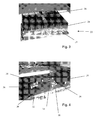
- printed circuit board assembly 10 which is designed and arranged in accordance with the teachings herein.
- This example of printed circuit board assembly 10 is for a modern gaming machine and is provided with high power processing capabilities and includes a higher power microprocessor chip and other power components.
- the majority of those components which do not in use generate substantial heat are located on an upper side 12 of the circuit board 10 and can be seen in the view of Figure 1 .
- the reverse or bottom side 14 of the printed circuit board 10 has located and fitted to its surface a plurality of high powered components 16-20, that is components which in use generate significant heat requiring cooling, along with other components.
- the printed circuit board 10 is arranged such that those components which do not generate significant heat during use are all located on one side (side 12) of printed circuit board whereas those components which generate significant heat and which require cooling during use are located on the opposite (side 14) of the printed circuit board 10.
- components such as microprocessor chips and other such critical components of a printed circuit are located on the upper surface of the printed circuit board for easy access and for coupling to heat sinks and the like.
- the arrangement of printed circuit board 10 as shown in Figures 1 and 2 could therefore be described as being contrary to that conventionally found in such devices.
- the casing 22 is, in this embodiment, of a type suitable for gaming and gambling machines and is made of a strong, sealed construction for security and regulatory purposes.
- the casing 22 is formed of a metal, such as aluminium, steel or any other suitable metal or metal alloy.
- the entirety of the casing 22 is made of metal or metal alloy, although it is envisaged that this could be made of other materials such as carbon fibre, plastics material and so on.
- At least the wall 24 of the casing 22 is made of a thermally conducted material.
- the wall 24 acts not only as a wall of the casing 22 but also as a heat sink, for which purpose the wall 24 is provided with an array of heat sink fins 26 of known characteristics.
- the casing 22 is in the preferred embodiment completely sealed, that is entirely closed, and provides access only for a plurality of electrical connector elements 28 located in one wall of the casing 22.
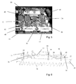
- FIG. 4 there is shown the wall 24 of the casing 22, turned upside down with respect to the view of Figure 3 so as to show the structure of the internal side 30 of the wall 24.
- the internal side or surface 30 of the wall 24 is provided with a plurality of raised blocks 32, 34, 36 which in this embodiment are of substantially square shape and raised relative to the general extent or plane of the surface 30 of the wall 24.
- These blocks 32-36 are heat conductive blocks and may either be formed integrally with the wall 24, for instance by machining, casting or the like, or may be separate elements attached to the internal surface 30 of the wall 24. In this latter option, the blocks would be made of a heat conductive material, preferably a metal such as aluminium or copper and can be attached to the surface 30 of the wall 24 by any suitable bonding, welding or soldering technique.
- each block 32-36 Located approximate each block 32-36 are provided, in this embodiment, at least one and as shown two fixing posts 38 for the purposes described below. These fixing posts 38 are preferably spaced from the periphery of their associated block 32-36 by no more than around 10 to 15 mm and preferably no more than around 5 mm.
- Figure 4 shows three heat conductive blocks 32-36 and each of these is substantially square in shape. It is to be appreciated that the number of blocks 32-36, their location on the surface 30 of the wall 24 and their shape, height and size will be dependent upon the shape and size of their associated heat generating components with which they are to interact, that is the heat generating components located on the lower surface 14 of the printed circuit board 10 of any particular application.
- FIG. 5 there is shown a view similar to that of Figure 4 , although in which the printed circuit board 10 is attached to the wall 24 of the casing 22.
- the printed circuit board 10 is disposed such that its lower surface 14 is adjacent and faces the surface 30 of the wall 24, whereas its upper 12 faces in the opposing direction and in practice into the general void within the casing 22.
- the heat generating components provided on the printed circuit board 10 all face the surface 30 of the wall 24, whereas those components of the printed circuit board 10 which do not generate significant heat during operation of the circuit, face into the void of the casing 22.
- FIG. 5 Also shown in Figure 5 are a plurality of sprung loaded connectors 40 which fix the printed circuit board 10 to the wall 24.
- These connectors 40 cooperate with respective posts 38 and in the preferred embodiment are in the form of a screw and nut arrangement, the screw being part of the connector 40 and the nut being part of the posts 38. It will be appreciated that the connectors 40 are arranged to align with their respective posts 38.
- Each connector 40 includes, in this embodiment, a screw element 42 and a coil spring 44 wrapped around the shank of the screw 42 and held in position by the enlarged head of the screw 42 such that the springs 44 press against the top surface 12 of the printed circuit board 10.
- these connectors 40 pass through appropriately sized apertures within the printed circuit board, these apertures being sized to allow the shank of the screw to pass but are small enough to hold the other end of the coil springs 44.
- the connectors 40 When the connectors 40 are fitted as shown in Figure 5 , they cause the coil springs 44 to become compressed such that these exert a constant biasing force to the printed circuit board 10 to press this against the wall 24 of the casing 22 and in particular to press the heat generating components 18-20 against their respective blocks 32-36 thereby to retain the components 16-20 in thermal contact with the blocks 32-36.
- the springs 44 and the positioning of the elements 40 are preferably chosen to take into account the following considerations:-
- thermal coupling element which may be a thermal grease or a thermal pad.
- Thermal grease and thermal pads are well known in the art for providing good thermal coupling between an electronic component and an associated heat sink.
- Thermal pads are typically made of a phase-change material which is able readily to conform to the surfaces of the electronic component and with the heat sink, in this case the surfaces of the component 16-20 and the surfaces of the blocks 32-36. Since thermal grease and thermal pads are well known in the art, it is not necessary to describe these in detail herein.
- the sprung loaded connectors 40 also have the function of compressing the thermal interface material (the thermal grease of pads) to enhance the thermal coupling between the circuit components 16-20 and their respective coupling blocks 32-36.
- FIG. 6 shows a side elevational view of the principal components of the printed circuit board 10 and wall 24.
- the circuit components or chips 16, 20 (the chip 18 not being visible in the view of Figure 6 ) abut and are in thermal contact with their respective raised blocks 36, 32 and preferably in contact therewith by means of a thermal grease or thermal pad located between the chips and conductive blocks.
- the connecting members 38, 40 hold the printed circuit board 10 against the wall 24 and the components 16-20 against their raised blocks 32-36 to maintain thermal contact between them.
- the heat generating components 16-20 of the printed circuit board assembly 10 are all located on a side of the printed circuit board 10 which faces the thermally conductive wall 24, that is the heat sink.
- the components on the upper surface 12 of the printed circuit board 10 face and extend into the main void in the casing 22 but these do not generate significant heat during operation of the assembly and therefore do not cause heating within the casing 22 which would warrant or necessitate cooling of the air within the casing 22, which would typically have to be achieved by fans or other specific cooling arrangement. This is avoided by ensuring that the high heat generating components are coupled thermally to the wall 24 and thus to the external heat sink which this provides.
- the material of the printed circuit board 10 can act as a thermal insulator, thus insulating the general void within the casing 22 from heat generated by the components 16-20.
- This arrangement has the advantage of maintaining the temperature within the void of the casing 22 at an acceptable level and of ensuring that heat generated by the components 16-20 is directed specifically to the heat sink of the wall 24.
- each of the raised conductive blocks 32-36 is shaped and sized for a particular component to which it is associated and in this regard the blocks 32-36 could also be of varying heights in dependence upon the depth of to which its associated component extends below the surface of the printed circuit board 10 and thus the distance between the surface of that component and the plane 30 of the wall 24.
- the provision of thermal grease or thermal pads will smooth out any imperfections in the facing surfaces of the component and device, thus maximising thermal contact between these two elements.
- the casing 22 can avoid the need for any thermal cooling within the void of the casing 22 in light of the fact that the arrangement avoids transfer of heat into that void.
- the casing 22 can be made smaller than prior art casings which require the provision of air flow within the void of the casing for cooling purposes.
- the arrangement taught herein results in a more compact and more secure casing 22 and control assembly.
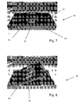
- casing 50 there is shown another embodiment of casing 50.
- This casing has generally the same characteristics as the casing 22 and is able to accommodate a printed circuit board such as that shown in Figures 1 and 2 .
- the casing 50 in the embodiment shown in Figures 7 and 8 includes only a portion of the upper wall 52 thereof which acts as a heat sink 54 and thus the upper wall 52 is only partially provided with heat sink fins.
- the casing 50 could have another design and indeed could have a design similar to that of the embodiment of Figures 3 to 5 .
- a fan arrangement 56 there is provided at the fins of the heat sink portion 54 a fan arrangement 56. It is to be understood that this fan arrangement 56 does not act on the interior of the casing 50, that is that the casing 50 is not provided with any aperture into it through the fan 56.
- the casing 50 remains fully sealed and the fan acts only upon, in this example, the central fins 58 of the heat sink portion 54 of the casing 50.
- the fan 56 in this example sits on top of and is coupled to the central fins 58.
- the fan 56 has the purpose of generating air flow within the fins 58 in order to maximise the cooling effect provided by the fins 58 and thus by the heat sink portion 54 of the casing 50.
- This fan mounted to the external surface of the casing 50, reduces the surface area of the heat sink required as well as the mass of the heat sink.
- the slim profile of the design is achievable by not having to have any air circulation or heat dissipating components within the casing 50.
- the fan 56 can be a large diameter fan having a slow rotation speed, which can prolong its reliability and operating life. It should be appreciated also that operation of the fan 56 is not necessarily essential to the functioning of the control unit of which the casing 50 forms a part and also that the fan 56 could be replaced if necessary without any need to gain access to the housed components within the casing 50 and thus without any need to compromise the security of those components.
- first and second plates 58 which lie on top of the fins and act to duct the air flow generated by the fan, thereby to keep this within the fins to assist in heat transfer.
- the arrangement of electrical components on the printed circuit board and the arrangement of the printed circuit board within the casing, as well as the design features of the casing, can meet the requirements of the slot machine industry described above and also other industries which require secure electronic control units.
- the embodiments described above enable high performance systems to be designed and manufactured based on components which dissipate large amounts of heat during their operation, whilst providing highly efficient cooling which ensures reliability of the equipment while at the same time eliminating ventilation holes which can create security issues.
- the arrangement can be implemented in a relatively low cost unit and without any major changes in existing design and production technology.
Landscapes
- Engineering & Computer Science (AREA)
- Physics & Mathematics (AREA)
- Thermal Sciences (AREA)
- Microelectronics & Electronic Packaging (AREA)
- Theoretical Computer Science (AREA)
- Human Computer Interaction (AREA)
- General Engineering & Computer Science (AREA)
- General Physics & Mathematics (AREA)
- Cooling Or The Like Of Electrical Apparatus (AREA)
Applications Claiming Priority (1)
| Application Number | Priority Date | Filing Date | Title |
|---|---|---|---|
| GBGB0922077.3A GB0922077D0 (en) | 2009-12-17 | 2009-12-17 | Electronic assembly and casing thereof |
Publications (2)
| Publication Number | Publication Date |
|---|---|
| EP2337437A2 true EP2337437A2 (de) | 2011-06-22 |
| EP2337437A3 EP2337437A3 (de) | 2011-10-19 |
Family
ID=41717127
Family Applications (1)
| Application Number | Title | Priority Date | Filing Date |
|---|---|---|---|
| EP10275125A Withdrawn EP2337437A3 (de) | 2009-12-17 | 2010-12-10 | Elektronische Anordnung und Gehäuse dafür |
Country Status (4)
| Country | Link |
|---|---|
| US (1) | US8373990B2 (de) |
| EP (1) | EP2337437A3 (de) |
| GB (1) | GB0922077D0 (de) |
| TW (1) | TW201146104A (de) |
Cited By (1)
| Publication number | Priority date | Publication date | Assignee | Title |
|---|---|---|---|---|
| US9526191B2 (en) | 2013-05-15 | 2016-12-20 | Dy 4 Systems Inc. | Fluid cooled enclosure for circuit module apparatus and methods of cooling a conduction cooled circuit module |
Families Citing this family (19)
| Publication number | Priority date | Publication date | Assignee | Title |
|---|---|---|---|---|
| DE102011012673A1 (de) * | 2010-03-17 | 2011-09-22 | Hitachi Automotive Systems, Ltd. | Elektronische Steuereinrichtung für Fahrzeuge |
| US9119327B2 (en) * | 2010-10-26 | 2015-08-25 | Tdk-Lambda Corporation | Thermal management system and method |
| KR20120055307A (ko) * | 2010-11-23 | 2012-05-31 | 삼성전기주식회사 | 방열기판 및 그 제조방법 |
| JP2013070028A (ja) * | 2011-09-07 | 2013-04-18 | Hitachi Automotive Systems Ltd | 電子制御装置 |
| ITTO20111168A1 (it) * | 2011-12-19 | 2013-06-20 | Gate Srl | Unita' elettronica, in particolare unita' di controllo per il motore di un elettroventilatore |
| FR3015178B1 (fr) * | 2013-12-13 | 2016-01-01 | Sagemcom Broadband Sas | Equipement electronique a double refroidissement |
| ITTO20140011U1 (it) * | 2014-01-23 | 2015-07-23 | Johnson Electric Asti S R L | Regolatore di tensione per un elettroventilatore di raffreddamento, particolarmente per uno scambiatore di calore di un autoveicolo |
| US10051763B2 (en) * | 2016-10-01 | 2018-08-14 | Intel Corporation | Local stress-relieving devices, systems, and methods for electronic assemblies |
| TWM541686U (zh) * | 2016-12-27 | 2017-05-11 | Micro-Star Int'l Co Ltd | 電子裝置 |
| JP6434559B2 (ja) | 2017-04-10 | 2018-12-05 | ファナック株式会社 | モータ駆動装置 |
| JP6911599B2 (ja) * | 2017-07-14 | 2021-07-28 | 株式会社デンソー | 電子制御装置 |
| JP6921710B2 (ja) * | 2017-10-30 | 2021-08-18 | 日立Astemo株式会社 | 電子制御装置 |
| JP7439468B2 (ja) * | 2019-11-20 | 2024-02-28 | 富士電機株式会社 | プログラマブルコントローラモジュール及びプログラマブルコントローラシステム |
| US11121053B2 (en) * | 2020-01-17 | 2021-09-14 | Asia Vital Components (China) Co., Ltd. | Die heat dissipation structure |
| EP3923689B1 (de) * | 2020-06-12 | 2024-04-24 | Aptiv Technologies AG | Kühlvorrichtung und verfahren zu deren herstellung |
| US11425842B2 (en) * | 2020-09-14 | 2022-08-23 | Hewlett Packard Enterprise Development Lp | Thermal design of an access point |
| US11341307B2 (en) * | 2020-10-22 | 2022-05-24 | Goldman Sachs & Co. LLC | Passively cooling hardware components |
| BE1030757B1 (de) * | 2022-08-05 | 2024-03-04 | Phoenix Contact Gmbh & Co | Technik zum Abführen von Wärme einer elektrischen Schaltung |
| WO2024028146A1 (de) * | 2022-08-05 | 2024-02-08 | Phoenix Contact Gmbh & Co. Kg | Technik zum abführen von wärme einer elektrischen schaltung |
Citations (5)
| Publication number | Priority date | Publication date | Assignee | Title |
|---|---|---|---|---|
| US5243218A (en) * | 1990-11-22 | 1993-09-07 | Fujitsu Limited | Cooling structure for electronics devices |
| EP1284592A2 (de) * | 2001-08-16 | 2003-02-19 | Nec Corporation | Vermittlungseinrichtung mit einem Gehäuse, dessen Wärmeleitfähigkeit verbessert ist |
| EP1508915A2 (de) * | 2003-08-18 | 2005-02-23 | Delphi Technologies, Inc. | Verfahren und Elektronikaufbau zur Hitzeabfuhr von einem Schaltungsbauteil |
| US20050201069A1 (en) * | 2004-03-15 | 2005-09-15 | Denso Corporation | Electronic device |
| US20080081518A1 (en) * | 2006-09-29 | 2008-04-03 | Samsung Electronics Co., Ltd. | User identification card connecting device for broadcast reception apparatus and broadcast reception apparatus having the same |
Family Cites Families (15)
| Publication number | Priority date | Publication date | Assignee | Title |
|---|---|---|---|---|
| EP0863694A1 (de) * | 1997-03-07 | 1998-09-09 | Telefonaktiebolaget Lm Ericsson | Gehäuse mit Wärmeabfuhr |
| DE19624475A1 (de) | 1996-06-19 | 1998-01-02 | Kontron Elektronik | Vorrichtung zum Temperieren elektronischer Bauteile |
| US6049469A (en) * | 1997-08-20 | 2000-04-11 | Dell Usa, L.P. | Combination electromagnetic shield and heat spreader |
| JPH11121666A (ja) * | 1997-10-20 | 1999-04-30 | Fujitsu Ltd | マルチチップモジュールの冷却装置 |
| TW438215U (en) * | 1998-02-10 | 2001-05-28 | D Link Corp | Heat sinks in an electronic production |
| US6180436B1 (en) * | 1998-05-04 | 2001-01-30 | Delco Electronics Corporation | Method for removing heat from a flip chip semiconductor device |
| JP2003289191A (ja) * | 2002-03-28 | 2003-10-10 | Denso Corp | 電子制御装置 |
| US6724631B2 (en) * | 2002-04-22 | 2004-04-20 | Delta Electronics Inc. | Power converter package with enhanced thermal management |
| US7023699B2 (en) * | 2002-06-10 | 2006-04-04 | Visteon Global Technologies, Inc. | Liquid cooled metal thermal stack for high-power dies |
| US6958910B2 (en) * | 2003-11-18 | 2005-10-25 | Kabushiki Kaisha Toshiba | Cooling apparatus for electronic apparatus |
| TWI278276B (en) * | 2005-08-15 | 2007-04-01 | Via Tech Inc | Electronic system |
| US20080037222A1 (en) * | 2006-02-17 | 2008-02-14 | Ddcip Technologies, Inc. | Heat dissipation assembly |
| US7679917B2 (en) * | 2007-02-02 | 2010-03-16 | Deck Joseph F | Electronic assembly cooling |
| JP5402200B2 (ja) * | 2009-04-20 | 2014-01-29 | 株式会社リコー | 熱移動機構及び情報機器 |
| US8081463B2 (en) * | 2009-06-16 | 2011-12-20 | Asia Vital Components Co., Ltd. | Water-cooled communication chassis |
-
2009
- 2009-12-17 GB GBGB0922077.3A patent/GB0922077D0/en not_active Ceased
-
2010
- 2010-12-10 EP EP10275125A patent/EP2337437A3/de not_active Withdrawn
- 2010-12-14 US US12/967,188 patent/US8373990B2/en active Active
- 2010-12-17 TW TW099144453A patent/TW201146104A/zh unknown
Patent Citations (5)
| Publication number | Priority date | Publication date | Assignee | Title |
|---|---|---|---|---|
| US5243218A (en) * | 1990-11-22 | 1993-09-07 | Fujitsu Limited | Cooling structure for electronics devices |
| EP1284592A2 (de) * | 2001-08-16 | 2003-02-19 | Nec Corporation | Vermittlungseinrichtung mit einem Gehäuse, dessen Wärmeleitfähigkeit verbessert ist |
| EP1508915A2 (de) * | 2003-08-18 | 2005-02-23 | Delphi Technologies, Inc. | Verfahren und Elektronikaufbau zur Hitzeabfuhr von einem Schaltungsbauteil |
| US20050201069A1 (en) * | 2004-03-15 | 2005-09-15 | Denso Corporation | Electronic device |
| US20080081518A1 (en) * | 2006-09-29 | 2008-04-03 | Samsung Electronics Co., Ltd. | User identification card connecting device for broadcast reception apparatus and broadcast reception apparatus having the same |
Cited By (2)
| Publication number | Priority date | Publication date | Assignee | Title |
|---|---|---|---|---|
| US9526191B2 (en) | 2013-05-15 | 2016-12-20 | Dy 4 Systems Inc. | Fluid cooled enclosure for circuit module apparatus and methods of cooling a conduction cooled circuit module |
| EP2804456B1 (de) * | 2013-05-15 | 2019-07-31 | DY 4 Systems Inc. | Flüssigkeitsgekühltes Gehäuse für Schaltungsmodulvorrichtung |
Also Published As
| Publication number | Publication date |
|---|---|
| GB0922077D0 (en) | 2010-02-03 |
| US8373990B2 (en) | 2013-02-12 |
| EP2337437A3 (de) | 2011-10-19 |
| US20110310560A1 (en) | 2011-12-22 |
| TW201146104A (en) | 2011-12-16 |
Similar Documents
| Publication | Publication Date | Title |
|---|---|---|
| US8373990B2 (en) | Electronic assembly and casing therefor | |
| JP4493579B2 (ja) | 電子筐体の中の気流を管理するためのシステム及び中央電子回路複合体 | |
| US7405936B1 (en) | Hybrid cooling system for a multi-component electronics system | |
| US7639498B2 (en) | Conductive heat transport cooling system and method for a multi-component electronics system | |
| US7345885B2 (en) | Heat spreader with multiple stacked printed circuit boards | |
| US7420808B2 (en) | Liquid-based cooling system for cooling a multi-component electronics system | |
| KR101005404B1 (ko) | 흡열 부재, 냉각 장치 및 전자 기기 | |
| US7486519B2 (en) | System for cooling a heat-generating electronic device with increased air flow | |
| US20050286229A1 (en) | Modular heat-dissipation assembly structure for a PCB | |
| US8111516B2 (en) | Housing used as heat collector | |
| US5953209A (en) | Push and pull dual-fan heat sink design | |
| EP1258921A2 (de) | Geneigte Montage eines Luftkühlers | |
| US9516782B2 (en) | Arrangement for cooling electronic components and/or assemblies | |
| KR100961683B1 (ko) | 컴퓨터 | |
| US6775134B2 (en) | Heat dissipation system | |
| KR20100126959A (ko) | 병렬형 방열핀 조립체를 이용한 자연냉각 방식의 산업용 컴퓨터 | |
| EP2910096B1 (de) | Elektronische vorrichtung mit kombination aus kühlkörper/gebläse oder lüfteranordnung | |
| CN107957768A (zh) | 一种电脑散热装置 | |
| CN221039936U (zh) | 一种工控机 | |
| US6108204A (en) | CPU heat sink | |
| WO2022270024A1 (ja) | 電子機器 | |
| JP2007281482A (ja) | ヒートシンクを使用する情報処理装置 | |
| KR101475455B1 (ko) | 방열구조를 갖는 전자장치, 그의 방열방법 및 방열 구조를 갖는 컴퓨터 | |
| JPH03208398A (ja) | 半導体装置 | |
| CN110895428A (zh) | 国产服务器及国产服务器主板模组 |
Legal Events
| Date | Code | Title | Description |
|---|---|---|---|
| PUAI | Public reference made under article 153(3) epc to a published international application that has entered the european phase |
Free format text: ORIGINAL CODE: 0009012 |
|
| AK | Designated contracting states |
Kind code of ref document: A2 Designated state(s): AL AT BE BG CH CY CZ DE DK EE ES FI FR GB GR HR HU IE IS IT LI LT LU LV MC MK MT NL NO PL PT RO RS SE SI SK SM TR |
|
| AX | Request for extension of the european patent |
Extension state: BA ME |
|
| PUAL | Search report despatched |
Free format text: ORIGINAL CODE: 0009013 |
|
| AK | Designated contracting states |
Kind code of ref document: A3 Designated state(s): AL AT BE BG CH CY CZ DE DK EE ES FI FR GB GR HR HU IE IS IT LI LT LU LV MC MK MT NL NO PL PT RO RS SE SI SK SM TR |
|
| AX | Request for extension of the european patent |
Extension state: BA ME |
|
| RIC1 | Information provided on ipc code assigned before grant |
Ipc: H05K 7/20 20060101AFI20110913BHEP |
|
| 17P | Request for examination filed |
Effective date: 20111214 |
|
| 17Q | First examination report despatched |
Effective date: 20120913 |
|
| APBK | Appeal reference recorded |
Free format text: ORIGINAL CODE: EPIDOSNREFNE |
|
| APBN | Date of receipt of notice of appeal recorded |
Free format text: ORIGINAL CODE: EPIDOSNNOA2E |
|
| APBR | Date of receipt of statement of grounds of appeal recorded |
Free format text: ORIGINAL CODE: EPIDOSNNOA3E |
|
| APAF | Appeal reference modified |
Free format text: ORIGINAL CODE: EPIDOSCREFNE |
|
| RAP1 | Party data changed (applicant data changed or rights of an application transferred) |
Owner name: QUIXANT PLC |
|
| APBT | Appeal procedure closed |
Free format text: ORIGINAL CODE: EPIDOSNNOA9E |
|
| STAA | Information on the status of an ep patent application or granted ep patent |
Free format text: STATUS: THE APPLICATION HAS BEEN WITHDRAWN |
|
| 18W | Application withdrawn |
Effective date: 20180703 |