EP2336711B1 - Dispositif de lancement pour projectile d'artillerie sous calibré - Google Patents
Dispositif de lancement pour projectile d'artillerie sous calibré Download PDFInfo
- Publication number
- EP2336711B1 EP2336711B1 EP10290641.9A EP10290641A EP2336711B1 EP 2336711 B1 EP2336711 B1 EP 2336711B1 EP 10290641 A EP10290641 A EP 10290641A EP 2336711 B1 EP2336711 B1 EP 2336711B1
- Authority
- EP
- European Patent Office
- Prior art keywords
- tooth
- projectile
- launching device
- base
- hinge
- Prior art date
- Legal status (The legal status is an assumption and is not a legal conclusion. Google has not performed a legal analysis and makes no representation as to the accuracy of the status listed.)
- Active
Links
- 239000004429 Calibre Substances 0.000 claims 1
- 230000002452 interceptive effect Effects 0.000 claims 1
- 210000000003 hoof Anatomy 0.000 description 4
- 238000010079 rubber tapping Methods 0.000 description 4
- 230000000694 effects Effects 0.000 description 3
- 238000010304 firing Methods 0.000 description 3
- 230000000295 complement effect Effects 0.000 description 2
- 239000008188 pellet Substances 0.000 description 2
- 230000000149 penetrating effect Effects 0.000 description 2
- 230000005540 biological transmission Effects 0.000 description 1
- 238000003754 machining Methods 0.000 description 1
- 238000012423 maintenance Methods 0.000 description 1
- 230000003071 parasitic effect Effects 0.000 description 1
- 230000035515 penetration Effects 0.000 description 1
- 230000000284 resting effect Effects 0.000 description 1
- 238000000926 separation method Methods 0.000 description 1
Images


Classifications
-
- F—MECHANICAL ENGINEERING; LIGHTING; HEATING; WEAPONS; BLASTING
- F42—AMMUNITION; BLASTING
- F42B—EXPLOSIVE CHARGES, e.g. FOR BLASTING, FIREWORKS, AMMUNITION
- F42B14/00—Projectiles or missiles characterised by arrangements for guiding or sealing them inside barrels, or for lubricating or cleaning barrels
- F42B14/06—Sub-calibre projectiles having sabots; Sabots therefor
- F42B14/064—Sabots enclosing the rear end of a kinetic energy projectile, i.e. having a closed disk shaped obturator base and petals extending forward from said base
Definitions
- the technical field of the invention is that launching devices for firing sub-calibrated artillery projectiles from a weapon tube.
- the solution of the pyrotechnic ejector is complex since the firing must be done accurately and reliably.
- the ejector pulse can disturb the trajectory of the projectile if this pulse is not perfectly coaxial with the trajectory.
- the maintenance of the hoof sectors on the projectile requires machining on the projectile to be able to place cutting pieces at the start of the stroke. These pieces require accurate calibration at break.
- Calibrated projectiles of medium caliber which comprise a shoe integral with a base and which bursts at the exit of the barrel of the weapon by the effect of the centrifugal force.
- Such projectiles are described for example by patents US 4419796 , DE-1262830 and US 4476785 .
- hooves are generally integral with the pellet and include rupture primers to facilitate the release of the projectile.
- Such solutions are not transferable to an artillery projectile whose rotation is reduced by the effect of a slipping belt.
- the patent GB-123501 succinctly describes a calibrated projectile of large caliber (406 mm) having joints of its hoof sectors on the base. These joints open by the action of centrifugal force. However, the joints are not clearly defined by this patent. These articulations make it possible to push the pellet towards the rear, clearing the projectile. It even seems that the sectors remain attached to the base at the level of their joints as the figure 3 suggest it.
- the invention proposes to improve the release of the projectile by connecting the shoe sectors to the base by a joint having a particular geometry not causing interference between the shoe sectors and the base.
- the spacing of the sectors is done symmetrically so as not to disturb the trajectory of the projectile and the base is also removed from the projectile by the support of the sectors on the base combined with the effort generated by its own aerodynamic drag .
- the subject of the invention is a device for launching a sub-calibrated artillery projectile, launch device comprising at its rear part a base comprising on its periphery a slipping belt, base containing a rear part of the projectile and having a thrust surface cooperating with a complementary surface of the rear of the projectile, launching device characterized in that it comprises at least two sectors of cylinder surrounding the projectile and intended to provide guidance by means of bands of outer annular bearing surfaces, sectors in contact by at least one form of internal support with the projectile, launching device comprising for each sector at least one articulation embodying an instantaneous axis of rotation, detachable articulation in flight and connecting the base to the sector considered, the articulation being constituted by at least one notch on the base, which cooperates with a tooth connected to the sector, the notch being bounded at the front by a sloped flat surface and at the back by a surf a stop perpendicular to the longitudinal axis of the projectile and cooperating
- the notch comprises an inclined surface forming an angle ⁇ , greater than or equal to 90 degrees with a notional plane F passing through the instantaneous axis of rotation and by a point of contact between the tooth and the inclined surface, any part of the tooth placed between the imaginary plane F and the abutment surface being at a distance from the instantaneous axis of rotation which is less than the distance separating the latter axis and the point of contact between the tooth and inclined surface.
- the articulation may comprise at least one means for adjusting the axial backlash between the base and the sector.
- This means of adjusting the axial backlash may comprise at each joint at least one integral pressure screw by a tapping of the tooth and bearing on the inclined surface of the notch.
- the device may comprise at least one clamping means of the hinge opposing the radial spacing between the base and the sectors when they are in contact with the projectile.
- This clamping means may thus comprise at each articulation at least one clamping screw traversing with a tapping the tooth, clamping screw oriented so as to penetrate towards the rear of the launching device and penetrating into a clearance made in the notch of the base, release in contact with the clamping screw so as to prevent any radial movement of the tooth with respect to the base.
- the surfaces of the clearance will be selected with dimensions such that they escape any interference with the clamping screw when the latter operates a rotation about the instantaneous axis of rotation in the direction of the opening of the sectors.
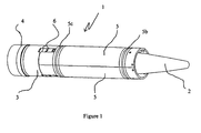
- the launching device 1 contains a projectile 2.
- This device is formed of a base 3 on its rear part.
- the base is equipped with a slip belt 4.
- the base is connected to three sectors 5 forming a shoe, only two of which are visible in the drawing.
- the connection is provided by an articulation 6 between each shoe sector 5 and the base 3.
- the outer part of the shoe sectors 5 is in contact with the inside of the weapon tube by means of bands 5b, 5c forming annular bearings (Tapes made for example of plastic).
- the device as shown in this drawing is in the configuration where it is once set up in the chamber of a weapon and on its entire trajectory in the barrel of the weapon.
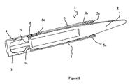
- the fins 2a of the projectile 2 are contained in the base 3.
- the base 3 comprises a thrust surface 3a bears with a corresponding rear surface of the projectile 2.
- the base 3 has not shown grooves opening on this thrust surface 3a so let the fins 2a pass during the separation base 3 / projectile 2.
- the hoof sectors 5 comprise flared inner support forms 5a in contact with the projectile 2 to center it on the longitudinal axis of the launching device.
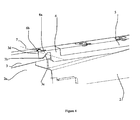
- the device 1 will open in the following manner.
- the pressure of the air exerted on the flared support forms 5a of each sector 5 will cause a symmetrical spacing (arrows 11) of the sectors 5 with breaking annular bearing bands 5b and 5c.
- These sectors 5 resting on the base 3 via the joints 6 will push the base 3 towards the rear, causing it to deviate from the rear of the projectile 2 and to release the fins 2a.
- no radial force on the projectile 2 will have been produced.
- the articulations 6 (which are not integral with the base) will become detached from the base 3 and each piece of the device 1 will be projected out of the trajectory of the projectile 2.
- each hinge 6 comprises a tooth 6a inserted in a corresponding notch 3b, made in the base 3.
- the notch 3b of a width substantially equal to the width of the tooth 6a, is delimited at the front by a flat surface inclined 3c and rear by a 3d surface, said abutment surface, perpendicular to the longitudinal axis of the launcher 1.
- the tooth 6a has at its base an edge 6b placed towards the rear of the device. This edge 6b brought into contact with the abutment surface 3d constitutes an instantaneous axis of rotation 7 of the tooth 6a during the opening of the sector 5.
- any part of the tooth located behind the plane F must be at a distance less than R from the instantaneous axis of rotation 7.
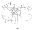
- a needle screw 9 (or clamping screw) is inclined so that it has a penetration angle facing the rear of the launching device 1.
- This clamping screw 9 passes through the tooth 6 by a tapping 6g to enter
- This clamping screw 9 will provide a clamping function by penetrating into the clearance 10 until it contacts the chamfer 10d of the clearance 10 but only on the part of the most oriented chamfer 10d. towards the rear of the launching device 1 (upper part of the clearance 10 on the figure 6 ).
- the interference between the clamping screw 9 and the chamfer 10d does not allow the tooth 6a to deviate radially from the base 3 in the direction Z.
- the clearance 10 is chosen with a sufficiently large diameter so that, during the rotation of the tooth 6a around the instantaneous axis of rotation 7, due to the opening of the sectors 5, the clearance 10 does not interfere with the screw 9.
- the clearance 10 may be an oblong grooving.
Landscapes
- Engineering & Computer Science (AREA)
- General Engineering & Computer Science (AREA)
- Toys (AREA)
- Pivots And Pivotal Connections (AREA)
Description
- Le domaine technique de l'invention est celui des dispositifs de lancement permettant le tir des projectiles d'artillerie sous calibrés à partir d'un tube d'arme.
- Afin d'améliorer la portée des projectiles d'artillerie de gros calibre, il est possible d'employer des projectiles dotés de surfaces de sustentation du type ailettes et de combiner ces moyens avec un sous calibrage du projectile afin de réduire sa trainée aérodynamique.
- Ces solutions nécessitent, d'une part l'emploi d'un moyen de découplage entre projectile et arme afin que l'effet de rotation généré par le tube de l'arme n'endommage pas les ailettes du projectile et d'autre part l'emploi de moyens de compensation du calibre entre le projectile et le tube.
- A la sortie du tube, ces moyens ayant joué leurs rôles il est nécessaire de les désolidariser du projectile sans entraver ou perturber la trajectoire du projectile.
- Pour cela il est connu dans le document
EP-0905473 d'employer une ceinture dérapante autour d'un culot venant pousser le projectile. Ce culot est désolidarisé du projectile par l'emploi d'un petit éjecteur pyrotechnique. De manière indépendante de l'éjection du culot, les éléments de compensation du calibre aussi appelés secteurs de sabot, placés à l'avant du projectile sont écartés du projectile par la pression dynamique de l'air. - La solution de l'éjecteur pyrotechnique est complexe puisque la mise à feu doit se faire de manière précise et fiable. L'impulsion de l'éjecteur peut venir perturber la trajectoire du projectile pour peu que cette impulsion ne soit pas parfaitement coaxiale à la trajectoire. D'autre part le maintien des secteurs de sabot sur le projectile nécessite de pratiquer des usinages sur le projectile pour pouvoir placer des pions sectionnables au départ du coup. Ces pions nécessitent un calibrage à la rupture précis.
- On connaît par ailleurs des projectiles sous calibrés de moyen calibre qui comportent un sabot solidaire d'un culot et qui éclate à la sortie du tube de l'arme par l'effet de la force centrifuge. De tels projectiles sont décrits par exemple par les brevets
US-4419796 ,DE-1262830 etUS-4476785 . - Ces sabots sont généralement solidaires du culot et comportent des amorces de rupture pour faciliter la libération du projectile. De telles solutions ne sont pas transposables à un projectile d'artillerie dont la rotation est réduite par l'effet d'une ceinture dérapante.
- On connaît aussi par le brevet
WO93/02333 - Le brevet
GB-123501 figure 3 le suggère. - Cette solution n'est pas transposable à un projectile d'artillerie doté d'une ceinture dérapante et pour lequel la force centrifuge est plus réduite et pour lequel le risque de perturbations du vol du projectile liées à des dissymétries d'ouvertures des segments du sabot est important. L'invention se propose d'améliorer la libération du projectile en reliant les secteurs de sabot au culot par une articulation comportant une géométrie particulière n'occasionnant pas d'interférences entre les secteurs de sabot et le culot. Par ce biais l'écartement des secteurs se fait de manière symétrique pour ne pas perturber la trajectoire du projectile et le culot est par ailleurs écarté du projectile par l'appui des secteurs sur le culot combiné à l'effort généré par sa propre trainée aérodynamique.
- De cette manière simple, aucune sollicitation parasite n'est appliquée au projectile.
- Ainsi, l'invention a pour objet un dispositif de lancement pour projectile d'artillerie sous calibré, dispositif de lancement comprenant à sa partie arrière un culot comportant sur sa périphérie une ceinture dérapante, culot contenant une partie arrière du projectile et comportant une surface de poussée coopérant avec une surface complémentaire de l'arrière du projectile, dispositif de lancement caractérisé en ce qu'il comprend au moins deux secteurs de cylindre entourant le projectile et destinés à assurer le guidage au moyen de bandes de portées annulaires extérieures, secteurs en contact par au moins une forme d'appui intérieure avec le projectile, dispositif de lancement comportant pour chaque secteur au moins une articulation matérialisant un axe instantané de rotation, articulation détachable en vol et reliant le culot au secteur considéré, l'articulation étant constituée par au moins une entaille sur le culot, qui coopère avec une dent liée au secteur, l'entaille étant délimitée à l'avant par une surface plane inclinée et à l'arrière par une surface butée perpendiculaire à l'axe longitudinal du projectile et coopérant avec une surface d'appui complémentaire au niveau de la dent, une arête de la dent étant en contact avec la surface butée et constituant l'axe instantané de rotation, la dent et l'entaille ayant par ailleurs une géométrie telle que la dent pivote lors de l'ouverture du secteur autour de l'axe instantané de rotation sans interférence avec la surface inclinée.
- Selon un mode de réalisation de l'invention, l'entaille comporte une surface inclinée formant un angle α, supérieur ou égal à 90 degrés avec un plan fictif F passant par l'axe de rotation instantané et par un point de contact entre la dent et la surface inclinée, toute partie de la dent placée entre le plan fictif F et la surface de butée se situant à une distance de l'axe instantané de rotation qui est inférieure à la distance séparant ce dernier axe et le point de contact entre la dent et la surface inclinée.
- Selon une autre caractéristique de l'invention l'articulation pourra comporter au moins un moyen de réglage du jeu axial d'appui entre le culot et le secteur.
- Ce moyen de réglage du jeu d'appui axial pourra comprendre au niveau de chaque articulation au moins une vis de pression solidaire par un taraudage de la dent et en appui sur la surface inclinée de l'entaille.
- Selon une autre caractéristique de l'invention le dispositif pourra comporter au moins un moyen de bridage de l'articulation s'opposant à l'écartement radial entre le culot et les secteurs quand ceux ci sont en contact avec le projectile.
- Ce moyen de bridage pourra ainsi comporter au niveau de chaque articulation au moins une vis de bridage traversant avec un taraudage la dent, vis de bridage orientée de manière à pénétrer vers l'arrière du dispositif de lancement et pénétrant dans un dégagement pratiqué dans l'entaille du culot, dégagement en contact avec la vis de bridage de manière à interdire tout mouvement radial de la dent vis à vis du culot.
- Les surfaces du dégagement seront choisies avec des dimensions telles qu'elles échappent à toute interférence avec la vis de bridage lorsque celle ci opère une rotation autour de l'axe de rotation instantané dans le sens de l'ouverture des secteurs.
- La description ci après illustrée par les dessins fournis en annexe permettra une meilleure compréhension de l'invention.
- La
figure 1 représente un dispositif de lancement contenant un projectile. - La
figure 2 représente une vue en coupe longitudinale du dispositif de lancement contenant un projectile. - La
figure 3 représente un dispositif de lancement contenant un projectile lorsque le dispositif se désolidarise du projectile. - La
figure 4 représente une vue de détail en coupe de l'articulation du dispositif de lancement, coupe longitudinale réalisée entre les vis. - La
figure 5 représente une vue de détail en coupe du moyen de réglage du jeu axial entre culot et secteur, coupe longitudinale réalisée au niveau d'une vis de pression. - La
figure 6 représente une vue de détail en coupe du moyen de bridage de l'articulation, coupe longitudinale réalisée au niveau d'une vis de bridage. - Selon la
figure 1 et suivant un mode de réalisation, le dispositif de lancement 1 contient un projectile 2. Ce dispositif est formé d'un culot 3 sur sa partie arrière. Le culot est équipé d'une ceinture dérapante 4. Le culot est relié à trois secteurs 5 formant un sabot, dont deux seulement sont visibles sur le dessin. La liaison est assurée par une articulation 6 entre chaque secteur 5 de sabot et le culot 3. La partie externe des secteurs de sabot 5 est en contact avec l'intérieur du tube d'arme grâce à des bandes 5b, 5c formant des portées annulaires (bandes réalisées par exemple en matière plastique). Le dispositif tel que représenté sur ce dessin est dans la configuration où il se trouve une fois mis en place dans la chambre d'une arme et sur toute sa trajectoire dans le tube de l'arme. - Selon la
figure 2 , les ailettes 2a du projectile 2 sont contenues dans le culot 3. Le culot 3 comporte une surface de poussée 3a en appui avec une surface arrière correspondante du projectile 2. Le culot 3 a des rainures non représentées débouchant sur cette surface de poussée 3a afin de laisser passer les ailettes 2a lors de la séparation culot 3 / projectile 2. Les secteurs de sabot 5 comportent des formes d'appui intérieures évasées 5a en contact avec le projectile 2 pour le centrer sur l'axe longitudinal du dispositif de lancement. - Selon la
figure 3 , dès la sortie du tube, le dispositif 1 va s'ouvrir de la manière suivante. La pression de l'air qui s'exerce sur les formes d'appui évasées 5a de chaque secteur 5 va provoquer un écartement symétrique (flèches 11) des secteurs 5 avec rupture des bandes de portées annulaires 5b et 5c. Ces secteurs 5 en appui sur le culot 3 par l'intermédiaire des articulations 6 vont pousser le culot 3 vers l'arrière, l'amenant à s'écarter de l'arrière du projectile 2 et à libérer les ailettes 2a. Durant toute cette phase, aucun effort radial sur le projectile 2 n'aura été produit. A la suite de cette phase les articulations 6 (qui ne sont pas solidaires du culot) vont se détacher du culot 3 et chaque morceau du dispositif 1 sera projeté hors de la trajectoire du projectile 2. - Selon la
figure 4 , chaque articulation 6 comprend une dent 6a insérée dans une entaille 3b correspondante, pratiquée dans le culot 3. L'entaille 3b, d'une largueur sensiblement égale à la largeur de la dent 6a, est délimitée à l'avant par une surface plane inclinée 3c et à l'arrière par une surface 3d, dite surface de butée, perpendiculaire à l'axe longitudinal du dispositif de lancement 1. La dent 6a comporte à sa base une arête 6b placée vers l'arrière du dispositif. Cette arête 6b mise en contact avec la surface butée 3d constitue un axe instantané de rotation 7 de la dent 6a lors de l'ouverture du secteur 5. - Selon la
figure 5 , deux vis de pression 8, traversant la dent 6a via un taraudage 6e, permettent par serrage de prendre appui sur la surface inclinée 3c, amenant ainsi la surface 6d, perpendiculaire à l'axe longitudinal du projectile 2, en contact avec la surface butée 3d du culot 3 pour garantir la transmission des efforts de tir du culot 3 sur le secteur 5. On a représenté en pointillés sur cette figure un plan fictif F passant par l'axe de rotation instantané 7 (qui est constitué par l'arête 6b) et par le point de contact 8a entre la vis de pression 8 et le plan incliné 3c. De même, dans le plan longitudinal du dispositif de lancement, on a aussi représenté sur cette figure un cercle C centré sur l'axe de rotation instantané 7 et de rayon R égal à la distance entre l'axe instantané de rotation 7 et le point de contact 8a entre la vis de pression 8 et le plan incliné 3c. - Pour qu'il n'y ait pas d'interférence entre la dent 6a ou les vis de pression 8 et la surface inclinée 3c de l'entaille 3b durant la rotation autour de l'axe instantané de rotation 7, il faut réunir deux conditions:
- L'angle α formé par le plan fictif F et le plan incliné 3c ne doit pas être inférieur à 90 degrés.
- L'intégralité de la partie de dent 6a incluant la vis 8 placée entre le plan fictif F et la surface d'appui 6d doit se trouver dans le cercle C.
- En d'autres termes, toute partie de la dent située derrière le plan F doit être à une distance inférieure à R de l'axe de rotation instantané 7.
- Selon la
figure 6 , une vis pointeau 9 (ou vis de bridage) est inclinée de sorte qu'elle ait un angle de pénétration orienté vers l'arrière du dispositif de lancement 1. Cette vis de bridage 9 traverse la dent 6 par un taraudage 6g pour rentrer dans un dégagement cylindrique 10. Cette vis de bridage 9 va assurer une fonction de bridage en pénétrant dans le dégagement 10 jusqu'à ce qu'elle soit en contact avec le chanfrein 10d du dégagement 10 mais seulement sur la partie du chanfrein 10d la plus orientée vers l'arrière du dispositif de lancement 1 (partie haute du dégagement 10 sur lafigure 6 ). L'interférence entre la vis de bridage 9 et le chanfrein 10d ne permet pas à la dent 6a de s'écarter radialement du culot 3 suivant la direction Z. - Le dégagement 10 est choisi avec un diamètre suffisamment grand pour que, lors de la rotation de la dent 6a autour de l'axe de rotation instantanée 7, dû à l'ouverture des secteurs 5, le dégagement 10 n'interfère pas avec la vis 9.
- Selon un autre mode de réalisation, le dégagement 10 pourra être un rainurage oblong.
Claims (7)
- Dispositif de lancement (1) pour projectile (2) d'artillerie sous calibré, dispositif de lancement (1) comprenant à sa partie arrière un culot (3) comportant sur sa périphérie une ceinture dérapante (4), culot contenant une partie arrière du projectile (2) et comportant une surface de poussée (3a) coopérant avec une surface complémentaire de l'arrière du projectile (2), dispositif de lancement (1) comprenant au moins deux secteurs (5) de cylindre entourant le projectile (2) et destinés à assurer le guidage au moyen de bandes de portées annulaires extérieures (5c et 5b), secteurs (5) en contact par au moins une forme d'appui intérieure (5a) avec le projectile (2), dispositif de lancement comportant pour chaque secteur (5) au moins une articulation (6) matérialisant un axe instantané de rotation (7), articulation (6) détachable en vol et reliant le culot (3) au secteur (5) considéré, dispositif de lancement caractérisé en ce que l'articulation (6) étant constituée par au moins une entaille (3b) sur le culot (3), qui coopère avec une dent (6a) liée au secteur (5), l'entaille (3b) étant délimitée à l'avant par une surface plane inclinée (3c) et à l'arrière par une surface de butée (3d) perpendiculaire à l'axe longitudinal du projectile (2) et coopérant avec une surface d'appui complémentaire au niveau de la dent (6a), une arête (6b) de la dent étant en contact avec la surface butée (3d) et constituant l'axe instantané de rotation (7), la dent (6a) et l'entaille (3b) ayant par ailleurs une géométrie telle que la dent (6a) pivote lors de l'ouverture du secteur (5) autour de l'axe instantané de rotation (7) sans interférence avec la surface inclinée (3c).
- Dispositif de lancement (1) selon la revendication 1, caractérisé en ce que l'entaille (3b) comporte une surface inclinée (3c) formant un angle (α) supérieur ou égal à 90 degrés avec un plan fictif (F) passant par l'axe de rotation instantané (7) et par un point de contact (8a) entre la dent (6a) et la surface inclinée (3c), toute partie de la dent (6a) placée entre le plan fictif F et la surface butée (3d) se situant à une distance de l'axe instantané de rotation (7) qui est inférieure à la distance séparant ce dernier axe et le point de contact (8a) entre la dent et la surface inclinée (3c).
- Dispositif de lancement (1) selon une des revendications 1 ou 2, caractérisé en ce que l'articulation (6) comporte au moins un moyen de réglage du jeu axial d'appui entre le culot (3) et le secteur (5).
- Dispositif de lancement (1) selon la revendication 3, caractérisé en ce que le moyen de réglage du jeu d'appui axial comprend au niveau de chaque articulation (6) au moins une vis de pression (8) solidaire par un taraudage (6e) de la dent (6a) et en appui sur la surface inclinée (3c) de l'entaille (3b).
- Dispositif de lancement (1) selon une des revendications 1 à 4, caractérisé en ce qu'il comporte au moins un moyen de bridage de l'articulation (6) s'opposant à l'écartement radial entre le culot (3) et les secteurs (5) quand ceux ci sont en contact avec le projectile (2).
- Dispositif de lancement (1) selon la revendication 5, caractérisé en ce que le moyen de bridage comporte au niveau de chaque articulation (6) au moins une vis de bridage (9) traversant avec un taraudage (6g) la dent (6a), vis de bridage (9) orientée de manière à pénétrer vers l'arrière du dispositif de lancement (1) et pénétrant dans un dégagement (10) pratiqué dans l'entaille (3b) du culot (3), dégagement (10) en contact avec la vis de bridage (9) de manière à interdire tout mouvement radial de la dent (6a) vis à vis du culot (3).
- Dispositif de lancement (1) selon la revendication 6, caractérisé en ce que les surfaces du dégagement (10) sont choisies avec des dimensions telles qu'elles échappent à toute interférence avec la vis de bridage (9) lorsque celle ci opère une rotation autour de l'axe de rotation instantané (7) dans le sens (11) de l'ouverture des secteurs (5).
Priority Applications (1)
| Application Number | Priority Date | Filing Date | Title |
|---|---|---|---|
| PL10290641T PL2336711T3 (pl) | 2009-12-21 | 2010-12-06 | Wyrzutnia artyleryjskiego pocisku podkalibrowego |
Applications Claiming Priority (1)
| Application Number | Priority Date | Filing Date | Title |
|---|---|---|---|
| FR0906206A FR2954485B1 (fr) | 2009-12-21 | 2009-12-21 | Dispositif de lancement pour projectile d'artillerie sous calibre. |
Publications (2)
| Publication Number | Publication Date |
|---|---|
| EP2336711A1 EP2336711A1 (fr) | 2011-06-22 |
| EP2336711B1 true EP2336711B1 (fr) | 2013-06-05 |
Family
ID=42313522
Family Applications (1)
| Application Number | Title | Priority Date | Filing Date |
|---|---|---|---|
| EP10290641.9A Active EP2336711B1 (fr) | 2009-12-21 | 2010-12-06 | Dispositif de lancement pour projectile d'artillerie sous calibré |
Country Status (5)
| Country | Link |
|---|---|
| US (1) | US8333153B2 (fr) |
| EP (1) | EP2336711B1 (fr) |
| ES (1) | ES2426471T3 (fr) |
| FR (1) | FR2954485B1 (fr) |
| PL (1) | PL2336711T3 (fr) |
Families Citing this family (11)
| Publication number | Priority date | Publication date | Assignee | Title |
|---|---|---|---|---|
| AU2010239639B2 (en) | 2009-02-02 | 2015-01-15 | Aerovironment | Multimode unmanned aerial vehicle |
| EP2475578B1 (fr) | 2009-09-09 | 2017-07-19 | AeroVironment, Inc. | Tube renforcé de lanceur de drone |
| EP2475575B1 (fr) * | 2009-09-09 | 2017-11-01 | AeroVironment, Inc. | UAV à ailes déployables et procédé de commande de vol |
| CN104540733B (zh) * | 2012-06-07 | 2016-09-21 | 威罗门飞行公司 | 用于在发射管内可拆卸地联接无人驾驶飞行器的系统 |
| KR101295318B1 (ko) * | 2013-01-09 | 2013-08-09 | 국방과학연구소 | 플레어가 장착된 탄두용 이탈피 |
| US8931416B2 (en) * | 2013-03-07 | 2015-01-13 | The United States Of America As Represented By The Secretary Of The Navy | Inert and pressure-actuated submunitions dispensing projectile |
| US10502515B2 (en) * | 2017-01-17 | 2019-12-10 | Raytheon Company | Launch piston brake |
| US10996037B2 (en) * | 2018-09-04 | 2021-05-04 | The United States Of America As Represented By The Secretary Of The Army | Obturator for robust and uniform discard |
| US10443993B1 (en) * | 2018-11-29 | 2019-10-15 | The United States Of America As Represented By The Secretary Of The Army | Spin discarding multiple projectile sabot |
| CN112611273B (zh) * | 2020-11-27 | 2022-08-23 | 江苏科技大学 | 一种多破片同步高速发射弹托及其使用方法 |
| FR3116894B1 (fr) * | 2020-12-02 | 2022-10-28 | Nexter Munitions | Projectile gyrostabilisé |
Family Cites Families (13)
| Publication number | Priority date | Publication date | Assignee | Title |
|---|---|---|---|---|
| GB123501A (en) * | 1918-02-12 | 1919-02-27 | John William Rooney | Improvements in Shells used in Warfare. |
| DE1262830B (de) * | 1964-09-02 | 1968-03-07 | Bundesrep Deutschland | Treibspiegel fuer Unterkalibergeschosse |
| DE2738121A1 (de) * | 1977-08-24 | 1979-03-01 | Rheinmetall Gmbh | Gewehrpatrone mit einem das unterkalibergeschoss umschliependen kunststoffmantel |
| US4296687A (en) * | 1979-07-16 | 1981-10-27 | The United States Of America As Represented By The Secretary Of The Army | Segmented sabot projectile |
| DE3131540C2 (de) * | 1981-08-08 | 1986-02-13 | Mauser-Werke Oberndorf Gmbh, 7238 Oberndorf | Treibspiegelgeschoß |
| US4419796A (en) * | 1981-09-24 | 1983-12-13 | Honeywell Inc. | Method of making spin stabilized discarding sabot projectile |
| US4841867A (en) * | 1987-12-28 | 1989-06-27 | Ford Aerospace Corporation | Discarding sabot projectile |
| FR2653873B1 (fr) * | 1989-10-26 | 1992-01-03 | France Etat Armement | Projectile sous-calibre comportant un noyau, un sabot et une chemise. |
| AT399582B (de) * | 1991-07-17 | 1995-06-26 | Steyr Daimler Puch Ag | Unterkalibriges geschoss mit treibspiegel |
| AT399583B (de) * | 1991-07-17 | 1995-06-26 | Steyr Daimler Puch Ag | Unterkalibriges geschoss mit abwerfbarem käfig |
| DE19650739C2 (de) * | 1996-12-06 | 1999-12-16 | Rheinmetall W & M Gmbh | Unterkalibriges Geschoß |
| FR2768809B1 (fr) | 1997-09-24 | 1999-10-15 | Giat Ind Sa | Projectile d'artillerie de campagne de gros calibre a longue portee |
| DE59806709D1 (de) * | 1997-11-19 | 2003-01-30 | Contraves Ag | Geschoss mit programmierbarem Zeitzünder |
-
2009
- 2009-12-21 FR FR0906206A patent/FR2954485B1/fr not_active Expired - Fee Related
-
2010
- 2010-12-01 US US12/957,939 patent/US8333153B2/en not_active Expired - Fee Related
- 2010-12-06 ES ES10290641T patent/ES2426471T3/es active Active
- 2010-12-06 EP EP10290641.9A patent/EP2336711B1/fr active Active
- 2010-12-06 PL PL10290641T patent/PL2336711T3/pl unknown
Also Published As
| Publication number | Publication date |
|---|---|
| PL2336711T3 (pl) | 2013-10-31 |
| EP2336711A1 (fr) | 2011-06-22 |
| US20110146525A1 (en) | 2011-06-23 |
| FR2954485B1 (fr) | 2012-05-11 |
| US8333153B2 (en) | 2012-12-18 |
| FR2954485A1 (fr) | 2011-06-24 |
| ES2426471T3 (es) | 2013-10-23 |
Similar Documents
| Publication | Publication Date | Title |
|---|---|---|
| EP2336711B1 (fr) | Dispositif de lancement pour projectile d'artillerie sous calibré | |
| EP1728043B1 (fr) | Balle de chasse a bague d'expansion | |
| CH634142A5 (fr) | Mecanisme de lancement d'un projectile sous-calibre. | |
| FR2599828A1 (fr) | Munition de petit ou moyen calibre a efficacite amelioree et portee limitee, en particulier pour la chasse | |
| EP2259006B1 (fr) | Dispositif d'ouverture et de verrouillage d'un empennage de munition | |
| EP3173326B1 (fr) | Roulement de pied de pale et son procede de fabrication, systeme, systeme oscillant et systeme tournant comprenant un tel roulement | |
| FR2726357A1 (fr) | Balle de chasse a fleche telescopee, comportant un sous-projectile associe a un lanceur | |
| FR3042238A1 (fr) | Roulement de pied de pale, systeme oscillant et systeme tournant | |
| EP3489617B1 (fr) | Projectile | |
| EP2578987B1 (fr) | Projectile gyrostabilisé | |
| EP0268535B1 (fr) | Ceinture dérapante pour projectile de tout calibre | |
| EP0728293B1 (fr) | Balle de chasse a double penetration et a portee reduite | |
| FR2626359A1 (fr) | Projectile a cage de poussee, sous-calibre et stabilise par ailettes | |
| EP4008992B1 (fr) | Projectile gyrostabilisé | |
| EP4025865A1 (fr) | Obus anti-aérien pour munition télescopée à double déverrouillage | |
| EP3121553B1 (fr) | Dispositif de sécurité et d'armement pour une fusée d'ogive et fusée comportant un tel dispositif | |
| EP0258125B1 (fr) | Balle de chasse sous-calibrée de type flèche à efficacité terminale accrue sur cibles molles | |
| EP2921812B1 (fr) | Projectile gyrostabilisé | |
| CA2176029C (fr) | Balle de chasse a double penetration et a portee reduite | |
| FR2677749A1 (fr) | Dispositif a projectiles comportant deux projectiles a effet cinetique sous-calibres. | |
| EP1988355A1 (fr) | Projectile générateur d'éclats | |
| FR2665764A1 (fr) | Projectile comportant un sabot constitue de plusieurs elements. | |
| FR2844589A1 (fr) | Projectile sous calibre a piece de guidage rapportee |
Legal Events
| Date | Code | Title | Description |
|---|---|---|---|
| PUAI | Public reference made under article 153(3) epc to a published international application that has entered the european phase |
Free format text: ORIGINAL CODE: 0009012 |
|
| AK | Designated contracting states |
Kind code of ref document: A1 Designated state(s): AL AT BE BG CH CY CZ DE DK EE ES FI FR GB GR HR HU IE IS IT LI LT LU LV MC MK MT NL NO PL PT RO RS SE SI SK SM TR |
|
| AX | Request for extension of the european patent |
Extension state: BA ME |
|
| 17P | Request for examination filed |
Effective date: 20111222 |
|
| GRAP | Despatch of communication of intention to grant a patent |
Free format text: ORIGINAL CODE: EPIDOSNIGR1 |
|
| GRAP | Despatch of communication of intention to grant a patent |
Free format text: ORIGINAL CODE: EPIDOSNIGR1 |
|
| GRAS | Grant fee paid |
Free format text: ORIGINAL CODE: EPIDOSNIGR3 |
|
| GRAA | (expected) grant |
Free format text: ORIGINAL CODE: 0009210 |
|
| AK | Designated contracting states |
Kind code of ref document: B1 Designated state(s): AL AT BE BG CH CY CZ DE DK EE ES FI FR GB GR HR HU IE IS IT LI LT LU LV MC MK MT NL NO PL PT RO RS SE SI SK SM TR |
|
| REG | Reference to a national code |
Ref country code: GB Ref legal event code: FG4D Free format text: NOT ENGLISH |
|
| REG | Reference to a national code |
Ref country code: CH Ref legal event code: EP |
|
| REG | Reference to a national code |
Ref country code: AT Ref legal event code: REF Ref document number: 615903 Country of ref document: AT Kind code of ref document: T Effective date: 20130615 |
|
| REG | Reference to a national code |
Ref country code: IE Ref legal event code: FG4D Free format text: LANGUAGE OF EP DOCUMENT: FRENCH |
|
| REG | Reference to a national code |
Ref country code: DE Ref legal event code: R096 Ref document number: 602010007560 Country of ref document: DE Effective date: 20130801 |
|
| REG | Reference to a national code |
Ref country code: SE Ref legal event code: TRGR |
|
| REG | Reference to a national code |
Ref country code: NO Ref legal event code: T2 Effective date: 20130605 |
|
| REG | Reference to a national code |
Ref country code: AT Ref legal event code: MK05 Ref document number: 615903 Country of ref document: AT Kind code of ref document: T Effective date: 20130605 |
|
| REG | Reference to a national code |
Ref country code: ES Ref legal event code: FG2A Ref document number: 2426471 Country of ref document: ES Kind code of ref document: T3 Effective date: 20131023 |
|
| PG25 | Lapsed in a contracting state [announced via postgrant information from national office to epo] |
Ref country code: SI Free format text: LAPSE BECAUSE OF FAILURE TO SUBMIT A TRANSLATION OF THE DESCRIPTION OR TO PAY THE FEE WITHIN THE PRESCRIBED TIME-LIMIT Effective date: 20130605 Ref country code: AT Free format text: LAPSE BECAUSE OF FAILURE TO SUBMIT A TRANSLATION OF THE DESCRIPTION OR TO PAY THE FEE WITHIN THE PRESCRIBED TIME-LIMIT Effective date: 20130605 Ref country code: GR Free format text: LAPSE BECAUSE OF FAILURE TO SUBMIT A TRANSLATION OF THE DESCRIPTION OR TO PAY THE FEE WITHIN THE PRESCRIBED TIME-LIMIT Effective date: 20130906 Ref country code: LT Free format text: LAPSE BECAUSE OF FAILURE TO SUBMIT A TRANSLATION OF THE DESCRIPTION OR TO PAY THE FEE WITHIN THE PRESCRIBED TIME-LIMIT Effective date: 20130605 Ref country code: FI Free format text: LAPSE BECAUSE OF FAILURE TO SUBMIT A TRANSLATION OF THE DESCRIPTION OR TO PAY THE FEE WITHIN THE PRESCRIBED TIME-LIMIT Effective date: 20130605 |
|
| REG | Reference to a national code |
Ref country code: PL Ref legal event code: T3 |
|
| REG | Reference to a national code |
Ref country code: NL Ref legal event code: VDEP Effective date: 20130605 |
|
| REG | Reference to a national code |
Ref country code: LT Ref legal event code: MG4D |
|
| PG25 | Lapsed in a contracting state [announced via postgrant information from national office to epo] |
Ref country code: HR Free format text: LAPSE BECAUSE OF FAILURE TO SUBMIT A TRANSLATION OF THE DESCRIPTION OR TO PAY THE FEE WITHIN THE PRESCRIBED TIME-LIMIT Effective date: 20130605 Ref country code: RS Free format text: LAPSE BECAUSE OF FAILURE TO SUBMIT A TRANSLATION OF THE DESCRIPTION OR TO PAY THE FEE WITHIN THE PRESCRIBED TIME-LIMIT Effective date: 20130605 Ref country code: BG Free format text: LAPSE BECAUSE OF FAILURE TO SUBMIT A TRANSLATION OF THE DESCRIPTION OR TO PAY THE FEE WITHIN THE PRESCRIBED TIME-LIMIT Effective date: 20130905 |
|
| PG25 | Lapsed in a contracting state [announced via postgrant information from national office to epo] |
Ref country code: LV Free format text: LAPSE BECAUSE OF FAILURE TO SUBMIT A TRANSLATION OF THE DESCRIPTION OR TO PAY THE FEE WITHIN THE PRESCRIBED TIME-LIMIT Effective date: 20130605 |
|
| PG25 | Lapsed in a contracting state [announced via postgrant information from national office to epo] |
Ref country code: SK Free format text: LAPSE BECAUSE OF FAILURE TO SUBMIT A TRANSLATION OF THE DESCRIPTION OR TO PAY THE FEE WITHIN THE PRESCRIBED TIME-LIMIT Effective date: 20130605 Ref country code: EE Free format text: LAPSE BECAUSE OF FAILURE TO SUBMIT A TRANSLATION OF THE DESCRIPTION OR TO PAY THE FEE WITHIN THE PRESCRIBED TIME-LIMIT Effective date: 20130605 Ref country code: CZ Free format text: LAPSE BECAUSE OF FAILURE TO SUBMIT A TRANSLATION OF THE DESCRIPTION OR TO PAY THE FEE WITHIN THE PRESCRIBED TIME-LIMIT Effective date: 20130605 Ref country code: IS Free format text: LAPSE BECAUSE OF FAILURE TO SUBMIT A TRANSLATION OF THE DESCRIPTION OR TO PAY THE FEE WITHIN THE PRESCRIBED TIME-LIMIT Effective date: 20131005 Ref country code: PT Free format text: LAPSE BECAUSE OF FAILURE TO SUBMIT A TRANSLATION OF THE DESCRIPTION OR TO PAY THE FEE WITHIN THE PRESCRIBED TIME-LIMIT Effective date: 20131007 |
|
| PG25 | Lapsed in a contracting state [announced via postgrant information from national office to epo] |
Ref country code: RO Free format text: LAPSE BECAUSE OF FAILURE TO SUBMIT A TRANSLATION OF THE DESCRIPTION OR TO PAY THE FEE WITHIN THE PRESCRIBED TIME-LIMIT Effective date: 20130605 Ref country code: NL Free format text: LAPSE BECAUSE OF FAILURE TO SUBMIT A TRANSLATION OF THE DESCRIPTION OR TO PAY THE FEE WITHIN THE PRESCRIBED TIME-LIMIT Effective date: 20130605 |
|
| PLBE | No opposition filed within time limit |
Free format text: ORIGINAL CODE: 0009261 |
|
| STAA | Information on the status of an ep patent application or granted ep patent |
Free format text: STATUS: NO OPPOSITION FILED WITHIN TIME LIMIT |
|
| PG25 | Lapsed in a contracting state [announced via postgrant information from national office to epo] |
Ref country code: DK Free format text: LAPSE BECAUSE OF FAILURE TO SUBMIT A TRANSLATION OF THE DESCRIPTION OR TO PAY THE FEE WITHIN THE PRESCRIBED TIME-LIMIT Effective date: 20130605 |
|
| 26N | No opposition filed |
Effective date: 20140306 |
|
| REG | Reference to a national code |
Ref country code: DE Ref legal event code: R097 Ref document number: 602010007560 Country of ref document: DE Effective date: 20140306 |
|
| PG25 | Lapsed in a contracting state [announced via postgrant information from national office to epo] |
Ref country code: MC Free format text: LAPSE BECAUSE OF FAILURE TO SUBMIT A TRANSLATION OF THE DESCRIPTION OR TO PAY THE FEE WITHIN THE PRESCRIBED TIME-LIMIT Effective date: 20130605 |
|
| PG25 | Lapsed in a contracting state [announced via postgrant information from national office to epo] |
Ref country code: LU Free format text: LAPSE BECAUSE OF FAILURE TO SUBMIT A TRANSLATION OF THE DESCRIPTION OR TO PAY THE FEE WITHIN THE PRESCRIBED TIME-LIMIT Effective date: 20131206 |
|
| REG | Reference to a national code |
Ref country code: IE Ref legal event code: MM4A |
|
| PG25 | Lapsed in a contracting state [announced via postgrant information from national office to epo] |
Ref country code: IE Free format text: LAPSE BECAUSE OF NON-PAYMENT OF DUE FEES Effective date: 20131206 |
|
| PG25 | Lapsed in a contracting state [announced via postgrant information from national office to epo] |
Ref country code: SM Free format text: LAPSE BECAUSE OF FAILURE TO SUBMIT A TRANSLATION OF THE DESCRIPTION OR TO PAY THE FEE WITHIN THE PRESCRIBED TIME-LIMIT Effective date: 20130605 |
|
| PG25 | Lapsed in a contracting state [announced via postgrant information from national office to epo] |
Ref country code: TR Free format text: LAPSE BECAUSE OF FAILURE TO SUBMIT A TRANSLATION OF THE DESCRIPTION OR TO PAY THE FEE WITHIN THE PRESCRIBED TIME-LIMIT Effective date: 20130605 Ref country code: CY Free format text: LAPSE BECAUSE OF FAILURE TO SUBMIT A TRANSLATION OF THE DESCRIPTION OR TO PAY THE FEE WITHIN THE PRESCRIBED TIME-LIMIT Effective date: 20130605 |
|
| PG25 | Lapsed in a contracting state [announced via postgrant information from national office to epo] |
Ref country code: MK Free format text: LAPSE BECAUSE OF FAILURE TO SUBMIT A TRANSLATION OF THE DESCRIPTION OR TO PAY THE FEE WITHIN THE PRESCRIBED TIME-LIMIT Effective date: 20130605 Ref country code: HU Free format text: LAPSE BECAUSE OF FAILURE TO SUBMIT A TRANSLATION OF THE DESCRIPTION OR TO PAY THE FEE WITHIN THE PRESCRIBED TIME-LIMIT; INVALID AB INITIO Effective date: 20101206 |
|
| REG | Reference to a national code |
Ref country code: CH Ref legal event code: PL |
|
| PG25 | Lapsed in a contracting state [announced via postgrant information from national office to epo] |
Ref country code: MT Free format text: LAPSE BECAUSE OF FAILURE TO SUBMIT A TRANSLATION OF THE DESCRIPTION OR TO PAY THE FEE WITHIN THE PRESCRIBED TIME-LIMIT Effective date: 20130605 |
|
| REG | Reference to a national code |
Ref country code: FR Ref legal event code: PLFP Year of fee payment: 6 |
|
| PG25 | Lapsed in a contracting state [announced via postgrant information from national office to epo] |
Ref country code: LI Free format text: LAPSE BECAUSE OF NON-PAYMENT OF DUE FEES Effective date: 20141231 Ref country code: CH Free format text: LAPSE BECAUSE OF NON-PAYMENT OF DUE FEES Effective date: 20141231 |
|
| REG | Reference to a national code |
Ref country code: FR Ref legal event code: PLFP Year of fee payment: 7 |
|
| REG | Reference to a national code |
Ref country code: FR Ref legal event code: PLFP Year of fee payment: 8 |
|
| PG25 | Lapsed in a contracting state [announced via postgrant information from national office to epo] |
Ref country code: AL Free format text: LAPSE BECAUSE OF FAILURE TO SUBMIT A TRANSLATION OF THE DESCRIPTION OR TO PAY THE FEE WITHIN THE PRESCRIBED TIME-LIMIT Effective date: 20130605 |
|
| PGFP | Annual fee paid to national office [announced via postgrant information from national office to epo] |
Ref country code: IT Payment date: 20221122 Year of fee payment: 13 |
|
| PGFP | Annual fee paid to national office [announced via postgrant information from national office to epo] |
Ref country code: ES Payment date: 20230102 Year of fee payment: 13 |
|
| PGFP | Annual fee paid to national office [announced via postgrant information from national office to epo] |
Ref country code: GB Payment date: 20231121 Year of fee payment: 14 |
|
| PGFP | Annual fee paid to national office [announced via postgrant information from national office to epo] |
Ref country code: SE Payment date: 20231121 Year of fee payment: 14 Ref country code: NO Payment date: 20231123 Year of fee payment: 14 Ref country code: FR Payment date: 20231122 Year of fee payment: 14 Ref country code: DE Payment date: 20231121 Year of fee payment: 14 |
|
| PGFP | Annual fee paid to national office [announced via postgrant information from national office to epo] |
Ref country code: PL Payment date: 20231127 Year of fee payment: 14 Ref country code: BE Payment date: 20231121 Year of fee payment: 14 |
|
| PGFP | Annual fee paid to national office [announced via postgrant information from national office to epo] |
Ref country code: ES Payment date: 20240102 Year of fee payment: 14 |