EP2335801A1 - Speicherbehälter zum Speichern gasförmiges Kraftstoffes - Google Patents
Speicherbehälter zum Speichern gasförmiges Kraftstoffes Download PDFInfo
- Publication number
- EP2335801A1 EP2335801A1 EP11002609A EP11002609A EP2335801A1 EP 2335801 A1 EP2335801 A1 EP 2335801A1 EP 11002609 A EP11002609 A EP 11002609A EP 11002609 A EP11002609 A EP 11002609A EP 2335801 A1 EP2335801 A1 EP 2335801A1
- Authority
- EP
- European Patent Office
- Prior art keywords
- storage container
- guide
- sorbent
- gas
- hydrogen
- Prior art date
- Legal status (The legal status is an assumption and is not a legal conclusion. Google has not performed a legal analysis and makes no representation as to the accuracy of the status listed.)
- Withdrawn
Links
Images


Classifications
-
- F—MECHANICAL ENGINEERING; LIGHTING; HEATING; WEAPONS; BLASTING
- F17—STORING OR DISTRIBUTING GASES OR LIQUIDS
- F17C—VESSELS FOR CONTAINING OR STORING COMPRESSED, LIQUEFIED OR SOLIDIFIED GASES; FIXED-CAPACITY GAS-HOLDERS; FILLING VESSELS WITH, OR DISCHARGING FROM VESSELS, COMPRESSED, LIQUEFIED, OR SOLIDIFIED GASES
- F17C5/00—Methods or apparatus for filling containers with liquefied, solidified, or compressed gases under pressures
- F17C5/06—Methods or apparatus for filling containers with liquefied, solidified, or compressed gases under pressures for filling with compressed gases
-
- B—PERFORMING OPERATIONS; TRANSPORTING
- B82—NANOTECHNOLOGY
- B82Y—SPECIFIC USES OR APPLICATIONS OF NANOSTRUCTURES; MEASUREMENT OR ANALYSIS OF NANOSTRUCTURES; MANUFACTURE OR TREATMENT OF NANOSTRUCTURES
- B82Y30/00—Nanotechnology for materials or surface science, e.g. nanocomposites
-
- C—CHEMISTRY; METALLURGY
- C01—INORGANIC CHEMISTRY
- C01B—NON-METALLIC ELEMENTS; COMPOUNDS THEREOF; METALLOIDS OR COMPOUNDS THEREOF NOT COVERED BY SUBCLASS C01C
- C01B3/00—Hydrogen; Gaseous mixtures containing hydrogen; Separation of hydrogen from mixtures containing it; Purification of hydrogen
- C01B3/0005—Reversible uptake of hydrogen by an appropriate medium, i.e. based on physical or chemical sorption phenomena or on reversible chemical reactions, e.g. for hydrogen storage purposes ; Reversible gettering of hydrogen; Reversible uptake of hydrogen by electrodes
- C01B3/001—Reversible uptake of hydrogen by an appropriate medium, i.e. based on physical or chemical sorption phenomena or on reversible chemical reactions, e.g. for hydrogen storage purposes ; Reversible gettering of hydrogen; Reversible uptake of hydrogen by electrodes characterised by the uptaking medium; Treatment thereof
- C01B3/0021—Carbon, e.g. active carbon, carbon nanotubes, fullerenes; Treatment thereof
-
- F—MECHANICAL ENGINEERING; LIGHTING; HEATING; WEAPONS; BLASTING
- F17—STORING OR DISTRIBUTING GASES OR LIQUIDS
- F17C—VESSELS FOR CONTAINING OR STORING COMPRESSED, LIQUEFIED OR SOLIDIFIED GASES; FIXED-CAPACITY GAS-HOLDERS; FILLING VESSELS WITH, OR DISCHARGING FROM VESSELS, COMPRESSED, LIQUEFIED, OR SOLIDIFIED GASES
- F17C11/00—Use of gas-solvents or gas-sorbents in vessels
- F17C11/005—Use of gas-solvents or gas-sorbents in vessels for hydrogen
-
- F—MECHANICAL ENGINEERING; LIGHTING; HEATING; WEAPONS; BLASTING
- F17—STORING OR DISTRIBUTING GASES OR LIQUIDS
- F17C—VESSELS FOR CONTAINING OR STORING COMPRESSED, LIQUEFIED OR SOLIDIFIED GASES; FIXED-CAPACITY GAS-HOLDERS; FILLING VESSELS WITH, OR DISCHARGING FROM VESSELS, COMPRESSED, LIQUEFIED, OR SOLIDIFIED GASES
- F17C7/00—Methods or apparatus for discharging liquefied, solidified, or compressed gases from pressure vessels, not covered by another subclass
-
- B—PERFORMING OPERATIONS; TRANSPORTING
- B01—PHYSICAL OR CHEMICAL PROCESSES OR APPARATUS IN GENERAL
- B01D—SEPARATION
- B01D2256/00—Main component in the product gas stream after treatment
- B01D2256/16—Hydrogen
-
- B—PERFORMING OPERATIONS; TRANSPORTING
- B01—PHYSICAL OR CHEMICAL PROCESSES OR APPARATUS IN GENERAL
- B01D—SEPARATION
- B01D2259/00—Type of treatment
- B01D2259/45—Gas separation or purification devices adapted for specific applications
- B01D2259/4525—Gas separation or purification devices adapted for specific applications for storage and dispensing systems
-
- B—PERFORMING OPERATIONS; TRANSPORTING
- B01—PHYSICAL OR CHEMICAL PROCESSES OR APPARATUS IN GENERAL
- B01D—SEPARATION
- B01D53/00—Separation of gases or vapours; Recovering vapours of volatile solvents from gases; Chemical or biological purification of waste gases, e.g. engine exhaust gases, smoke, fumes, flue gases, aerosols
- B01D53/02—Separation of gases or vapours; Recovering vapours of volatile solvents from gases; Chemical or biological purification of waste gases, e.g. engine exhaust gases, smoke, fumes, flue gases, aerosols by adsorption, e.g. preparative gas chromatography
- B01D53/04—Separation of gases or vapours; Recovering vapours of volatile solvents from gases; Chemical or biological purification of waste gases, e.g. engine exhaust gases, smoke, fumes, flue gases, aerosols by adsorption, e.g. preparative gas chromatography with stationary adsorbents
- B01D53/0407—Constructional details of adsorbing systems
-
- F—MECHANICAL ENGINEERING; LIGHTING; HEATING; WEAPONS; BLASTING
- F17—STORING OR DISTRIBUTING GASES OR LIQUIDS
- F17C—VESSELS FOR CONTAINING OR STORING COMPRESSED, LIQUEFIED OR SOLIDIFIED GASES; FIXED-CAPACITY GAS-HOLDERS; FILLING VESSELS WITH, OR DISCHARGING FROM VESSELS, COMPRESSED, LIQUEFIED, OR SOLIDIFIED GASES
- F17C2203/00—Vessel construction, in particular walls or details thereof
- F17C2203/03—Thermal insulations
- F17C2203/0304—Thermal insulations by solid means
-
- F—MECHANICAL ENGINEERING; LIGHTING; HEATING; WEAPONS; BLASTING
- F17—STORING OR DISTRIBUTING GASES OR LIQUIDS
- F17C—VESSELS FOR CONTAINING OR STORING COMPRESSED, LIQUEFIED OR SOLIDIFIED GASES; FIXED-CAPACITY GAS-HOLDERS; FILLING VESSELS WITH, OR DISCHARGING FROM VESSELS, COMPRESSED, LIQUEFIED, OR SOLIDIFIED GASES
- F17C2221/00—Handled fluid, in particular type of fluid
- F17C2221/01—Pure fluids
- F17C2221/012—Hydrogen
-
- F—MECHANICAL ENGINEERING; LIGHTING; HEATING; WEAPONS; BLASTING
- F17—STORING OR DISTRIBUTING GASES OR LIQUIDS
- F17C—VESSELS FOR CONTAINING OR STORING COMPRESSED, LIQUEFIED OR SOLIDIFIED GASES; FIXED-CAPACITY GAS-HOLDERS; FILLING VESSELS WITH, OR DISCHARGING FROM VESSELS, COMPRESSED, LIQUEFIED, OR SOLIDIFIED GASES
- F17C2270/00—Applications
- F17C2270/01—Applications for fluid transport or storage
- F17C2270/0134—Applications for fluid transport or storage placed above the ground
- F17C2270/0139—Fuel stations
-
- F—MECHANICAL ENGINEERING; LIGHTING; HEATING; WEAPONS; BLASTING
- F17—STORING OR DISTRIBUTING GASES OR LIQUIDS
- F17C—VESSELS FOR CONTAINING OR STORING COMPRESSED, LIQUEFIED OR SOLIDIFIED GASES; FIXED-CAPACITY GAS-HOLDERS; FILLING VESSELS WITH, OR DISCHARGING FROM VESSELS, COMPRESSED, LIQUEFIED, OR SOLIDIFIED GASES
- F17C2270/00—Applications
- F17C2270/01—Applications for fluid transport or storage
- F17C2270/0165—Applications for fluid transport or storage on the road
- F17C2270/0168—Applications for fluid transport or storage on the road by vehicles
-
- Y—GENERAL TAGGING OF NEW TECHNOLOGICAL DEVELOPMENTS; GENERAL TAGGING OF CROSS-SECTIONAL TECHNOLOGIES SPANNING OVER SEVERAL SECTIONS OF THE IPC; TECHNICAL SUBJECTS COVERED BY FORMER USPC CROSS-REFERENCE ART COLLECTIONS [XRACs] AND DIGESTS
- Y02—TECHNOLOGIES OR APPLICATIONS FOR MITIGATION OR ADAPTATION AGAINST CLIMATE CHANGE
- Y02E—REDUCTION OF GREENHOUSE GAS [GHG] EMISSIONS, RELATED TO ENERGY GENERATION, TRANSMISSION OR DISTRIBUTION
- Y02E60/00—Enabling technologies; Technologies with a potential or indirect contribution to GHG emissions mitigation
- Y02E60/30—Hydrogen technology
- Y02E60/32—Hydrogen storage
-
- Y—GENERAL TAGGING OF NEW TECHNOLOGICAL DEVELOPMENTS; GENERAL TAGGING OF CROSS-SECTIONAL TECHNOLOGIES SPANNING OVER SEVERAL SECTIONS OF THE IPC; TECHNICAL SUBJECTS COVERED BY FORMER USPC CROSS-REFERENCE ART COLLECTIONS [XRACs] AND DIGESTS
- Y10—TECHNICAL SUBJECTS COVERED BY FORMER USPC
- Y10T—TECHNICAL SUBJECTS COVERED BY FORMER US CLASSIFICATION
- Y10T29/00—Metal working
- Y10T29/49—Method of mechanical manufacture
- Y10T29/49826—Assembling or joining
Definitions
- the present invention relates to the technical field of storing and providing gaseous fuels, in particular hydrogen.
- the present invention relates in particular to a storage container for gaseous fuels and their applications.
- the present invention relates to a storage container according to the preamble of claim 1, a tank system according to the preamble of claim 21, a filling / discharging nozzle according to the preamble of claim 24 for filling and / or discharging a storage container, a system for providing a sorption material According to the preamble of claim 29, a method for providing sorption material for a storage container according to the preamble of claim 36 and a method for filling a storage container according to the preamble of claim 39.
- Storage tanks can be designed, for example, as so-called adsorption storage.
- the invention is not limited to this particular application.
- the storage system according to the present invention is applicable to any type of storage in which a storage container, in particular consisting of an inner container and outer container, is used to store a medium to be stored, for example a gas, a liquid or possibly also a different type of filling in a solid.
- the present invention relates to the technical field of hydrogen storage, which has recently gained considerable importance.
- Hydrogen is considered to be zero emissions fuel with respect to emissions of toxic or climate-affecting process gases because its use, for example, in thermal engines, in fuel cell applications or the like, produces almost only water. Consequently, the provision of suitable storage means for the efficient storage of hydrogen is an important goal which must be achieved before widespread use of hydrogen as a fuel can occur.
- adsorb hydrogen to suitable adsorbents (for example based on carbon) - also called sorbents or sorbents in the context of the invention.
- adsorption materials are, for example, activated carbon.
- Adsorption in the light of the present invention means the addition of gases or solutes at the interface of a solid or liquid phase, the sorbent.
- the sorbent for example, serves as storage material for the hydrogen.
- the term "sorbent" - in the plural "sorbents" - is thus used in the context of the present invention to designate the adsorption or storage agent (eg activated carbon) as such (sometimes the more specific term is also used interchangeably in the context of the present invention).
- the storage or sorption material is preferably accommodated in a storage container, the adsorption storage, in which the hydrogen is stored.
- desorption This is the process of counteracting adsorption. If In the further course of the description, reference is made to the process of adsorption, so of course the process of desorption should always be taken into account as well.
- desorption the hydrogen adsorbed on the adsorption material is released or separated from the sorbent or sorption material with the application of energy.
- the problem with the adsorption of media on adsorbent materials is often the management of the heat of reaction that occurs, i. H. Adsorption energies or desorption energies during adsorption or desorption. This can lead to local cooling or overheating of the adsorbents, since the adsorbents, such as activated carbon with high specific surface area, have only poor thermal conductivities.
- the convection as a means of heat transfer in the gas phase is severely limited due to the large friction losses on the pore walls of the adsorbents.
- the kinetics of adsorption and desorption are significantly limited by the slow gas transport through the porous structure of the adsorbents.
- the sorbents are mostly porous and have a high specific surface area. They are therefore often very poor thermal conductivity.
- heat of adsorption occurs, which in turn causes the material to be heated and the adsorbed gas to be partially desorbed.
- One must therefore try to transport the heat away.
- desorption In this one must bring heat to the adsorption to bring about the desorption.
- the temperature of the storage system and the storage medium advantageously reduced to cryogenic areas to achieve better storage capacity.
- This requires the removal of a large amount of energy.
- the energy released by adsorption from the storage medium which also has to be dissipated.
- energy must be supplied to the storage system in order to increase its temperature to room temperature range and to provide the necessary desorption energy.
- a storage system for storing a medium, for example hydrogen and a method for loading / unloading a storage system with a storage medium are described.
- the storage system has a storage container, which is advantageously designed as a pressure vessel.
- this storage container is a storage material in the form of a sorbent.
- a gas to be stored, for example hydrogen is introduced into the storage container and adsorbed on the sorbent under suitable conditions. To remove the gas, this is subsequently desorbed first.
- the sorbent remains in the storage tank the whole time, the adsorption thus takes place within the storage tank.
- a major problem of sorption reservoirs is the discharge of sorption heat released during the refueling process.
- the Sorptionsenthalpie released during refueling must be removed at short notice.
- a heat exchanger with a correspondingly large cooling capacity is necessary.
- the need for heat removal significantly prolongs the refueling process.
- the additional volume and weight requirements reduce the volumetric and gravimetric storage capacities and also increase the costs for decentralized heat management.
- a great advantage of the present invention is, for example, also a complete recycling system in which discharged sorbents or sorption materials are again exchanged for laden sorbents or sorption materials. For example, from time to time a certain percentage of the sorbents may be exchanged for freshly made sorbents. Due to the high abrasion resistance of the sorbents used according to the invention, there is a possibility of use for a product batch of sorbents for many years.
- a storage container for storing a sorbent material
- the storage container having a pressure vessel, a connector to an external delivery system and at least one sorbent material stored therein at least during operational use of the storage container, and a transport guide for loading and / or unloading the storage container is equipped with sorbent material, wherein the sorbent material comprises a sorbent and an adsorbate adsorbed thereto, in particular a gaseous fuel, preferably hydrogen.
- the storage container according to the invention is characterized in that on the one hand at least a second guide for supplying and / or discharging a gas (gas guide) is provided and that on the other hand, the sorbent based on high performance adsorbents based on activated carbon in the form of discrete activated carbon grains, preferably in spherical form , wherein at least 70% of the total pore volume of the high-performance adsorbents are formed by micropores having pore diameters of ⁇ 20 ⁇ (ie, in other words, highly microporous high-performance adsorbents are employed).
- the high-performance adsorbents used according to the invention have a total pore volume according to Gurvich of at least 0.7 cm 3 / g, wherein at least 70% of this total pore volume is formed by micropores with pore diameters of ⁇ 20 ⁇ .
- a highly microporous activated carbon of the aforementioned type is particularly suitable for the present invention, since on the one hand such an activated carbon an extremely high loading capacity with respect to the relevant
- the present invention has for its object to provide solutions by means of which the aforementioned disadvantages can be at least largely avoided or at least mitigated.
- solutions for storing gases, in particular hydrogen are to be provided, by means of which the resulting sorption heat can be dissipated, in particular without any time problems and with low cost and energy expenditure.
- the present invention is based on the idea that with gas, for example hydrogen, laden sorbents in an external system, such as a gas station, are stored and then replaced with spent sorbent in a storage container, such as a mobile tank.
- gas for example hydrogen
- laden sorbents in an external system such as a gas station
- spent sorbent in a storage container such as a mobile tank.
- a filling process for example a refueling process
- the spent or desorbed sorption materials are then in the external system - and no longer, as usual, in the storage container itself - again with gas, such as hydrogen, loaded and are available for a refilling process.
- trained or selected sorbents are required in a special way, which are also provided by the present invention. exclusive examples in the further course of the description explained.
- the storage container has an inner container for receiving the sorbent, which then represents the actual pressure vessel. Furthermore, a second, outside of the inner container befindaji outer container is advantageously provided, which has the function of an insulating container in the first place. The outer container may also serve to protect the inner container from damage.
- an isolation region is provided between the inner container and the outer container.
- This isolation area may be formed, for example, as a kind of cavity in which an insulating material may be located.
- the insulation material may be solid, liquid or gaseous. It is also conceivable that the insulation region is formed in the form of an insulating layer, which may be, for example, a film, mat or the like, which is arranged between the outer and inner container.
- the aim is a mechanically simple as possible loading and unloading system to avoid complex structures and moving parts within the storage container.
- the basic idea is to transport the granular, preferably granular or spherical sorption material via a gas stream at virtually any pressure, in particular approximately up to about 40 bar.
- the storage container should basically have two openings / feedthroughs for media, which are referred to below as guides.
- a first tour is the so-called transport guide, which is primarily responsible for the transport of the sorption materials.
- This guide is used, for example, for transporting the sorption material Kraft or fuel gases, in particular hydrogen, and on the other hand, such an activated carbon has an optimum for the purposes of the invention adsorption and desorption.
- the activated carbon in question has an extremely high abrasion resistance and thus has excellent wear properties, which allows their long-term use, especially over several months or even years, and further a recycle.
- a suitable for the purposes of the invention activated carbon is particularly in the German patent application 10 2006 048 790.7 of October 12, 2006 and the parallel German utility model application 20 2006 016 898.2 of November 4, 2006, the entire disclosure of which is hereby incorporated by reference, and is otherwise commercially available from Blücher GmbH, Erkrath, and Adsor-Tech GmbH, Premnitz.
- the storage container according to the invention is designed such that it can absorb externally supplied sorption material to which a gas is adsorbed.
- the storage container In its operating state, the storage container is filled with sorption material and can deliver adsorbed gas, for example hydrogen, as needed to a consumer.
- adsorbed gas for example hydrogen
- the storage container is designed in a special way. How this can be realized in detail, is based on some advantageous, but not from the gas station to the tank system as well as from the tank system to the gas station.
- a second guide is formed by a gas guide, through which gases can be introduced into and out of the container, this will be explained in more detail in the course of the description.
- the transport guide and / or the gas guide can be tubular.
- the invention is not limited to specific tube cross sections. These arise rather from the fluidic requirements.
- a circular or oval cross-section is provided.
- the transport guide and / or the gas guide can be designed in the form of a nozzle. This makes it particularly advantageous to realize a suitable flow course within the storage container.
- At least one filter element for filtering sorption material and / or sorbent may preferably be provided in the gas guide.
- the first passage is advantageously equipped with a relatively large diameter in relation to the particle size of the sorption material, for example a diameter of at least 50 times the particle size.
- the second passage is advantageously designed nozzle-shaped and has a filter which retains penetrating Sorptionsmaterialp
- This nozzle serves as a gas outlet when filling the tank system (storage tank).
- a carrier gas required for this purpose for example hydrogen carrier gas
- gas for example hydrogen gas
- the tank system Due to the high flow rate at the outlet and the position of the nozzle in the tank system sorption material present in the tank system is whirled up and over the first passage (transport) transported by the gas flow from the tank system. Thus, the tank system can be loaded and unloaded.
- the transport guide and the gas guide can be connected to one another in the storage container and form a pipe loop.
- At least one rotatable flap preferably two flaps, for changing the flow rate within the pipe loop can be provided in the pipe loop.
- the pipe loop can be interrupted in two places by 90 ° rotatable, flow-driven flaps.
- the aim of these valves is the deflection of the flow (sorption + carrier gas) during the filling process.
- the first flap closes the passage through the pipe system and thereby causes the introduction of the sorbent material into the storage container.
- the carrier gas is conveyed via the second flap back into the pipe system and can be returned, for example, to the pump.
- the carrier gas flows through the pipe loop in the opposite direction.
- a narrowing of the pipe loop (cf the venturi principle described above) leads to a reduction of the static pressure in the pipe section and thereby to a suction of sorption material from the storage tank.
- the sorbent material is dispersed in the carrier stream and discharged from the storage container.
- a filter in front of the flap (s) can prevent the unwanted discharge of sorbent material.
- at least one filter element for filtering sorbent material and / or sorbent may be provided in the pipe loop be, wherein the filter element is preferably arranged in the region of the rotatable flap (s).
- the storage container at least during the filling process and / or discharge process in a (r) inclination, based on a horizontal or vertical reference plane (depending on whether the storage container is arranged vertically or horizontally), be brought or aligned.
- a slight inclination of the storage tank and a favorable positioning of the Venturi piece near the lowest point take over the task of transporting the sorption material into the reach of the suction by using gravity on the inclined plane.
- the transport guide and the gas guide are combined in a single guide and that the guide is designed as a receptacle for a filling / discharge nozzle.
- This embodiment is used in particular with a further described below in more detail filling / discharge nozzle.
- the advantage of this embodiment is the decoupling of the components required for the filling and discharge from the storage container, and thus a substantial saving in weight and heat capacity.
- the task of supplying and discharging sorbent material and carrier gas takes a introduced into the storage container neck, which can also be designed flexibly and advantageously characterized in that the length of the nozzle can be readjusted in the storage container to stir up the sorbent as close as possible and to be able to pay.
- At least one sensor element can be provided for measuring operation-specific properties of the storage container and / or the sorption material and / or the sorbent. Such measured values, as will be explained in more detail below, can be used to further optimize the filling and discharging process.
- At least one interface can be provided for the transmission of values detected via the at least one sensor element. This may be particularly advantageous to a data interface.
- the storage container can be used for storing any gaseous media, it can be particularly preferably designed as a storage tank for a gaseous fuel, in particular for hydrogen.
- high performance adsorbents based on activated carbon with high microporosity are preferred in the context of the present invention as the sorbent used, as is the subject of the German patent application 10 2006 048 790.7 and the parallel German utility model application 20 2006 016 898.2 , both in the name of Blücher GmbH, Erkrath, are.
- Such high-performance activated carbon adsorbents in the form of discrete activated charcoal grains, preferably in spherical form, are characterized by a high microporosity, wherein generally at least 70% of the total pore volume of the high-performance adsorbents used according to the invention are formed by micropores with pore diameters of s 20 ⁇ .
- the high-performance adsorbents used according to the invention have a total pore volume according to Gurvich of at least 0.7 cm 3 / g, wherein at least 70% of this total pore volume is formed by micropores with pore diameters of ⁇ 20 ⁇ .
- the active carbon-based high-performance adsorbents of the abovementioned type used as sorbents in the context of the present invention have an average pore diameter of at most 30 ⁇ and / or a BET surface area of at least 1500 m 2 / g.
- the high-performance adsorbents or activated carbons used according to the invention are distinguished, in particular, by a large overall porosity and a simultaneously large BET surface area.
- the mechanical strength, in particular the abrasion resistance and the bursting or compressive strength, of the high-performance adsorbents used according to the invention - in contrast to comparable highly porous activated carbons of the prior art - are extremely high, so that the invention used high performance adsorbents or activated carbons are also suitable for such applications in which they are exposed to high mechanical loads.
- All BET surface area information refers to the determination according to ASTM D6556-04.
- MP-BET MultiPoint BET determination method
- p / p 0 partial pressure range p / p 0 of 0.05 to 0.1 for determining the BET surface area.
- the determination of the mean pore diameter is based on the respective nitrogen isotherms.
- the total pore volume according to Gurvich of the high-performance adsorbents used according to the invention is at least 0.7 cm 3 / g, in particular at least 0.8 cm 3 / g, preferably at least 0.9 cm 3 / g, particularly preferably at least 1.0 cm 3 / g, and can reach values of up to 1.5 cm 3 / g, in particular up to 1.6 cm 3 / g, preferably up to 1.8 cm 3 / g.
- the total pore volume according to Gurvich of the high-performance adsorbents used according to the invention is in the range of 0.7 to 1.8 cm 3 / g, in particular 0.8 to 1.6 cm 3 / g, preferably 0.9 to 1.5 cm 3 / g.
- a special feature of the high-performance adsorbents used according to the invention is, inter alia, that they have a very large total pore volume according to Gurvich, so that a large adsorption capacity is provided, with a high proportion of micropores being required.
- micropores refers to those pores having pore diameters up to 20 ⁇
- mesopores refers to pores having pore diameters of> 20 ⁇ to 50 ⁇ inclusive
- macropores refers to pores having pore diameters> 50 ⁇ .
- the micropore volume of the high-performance adsorbents used according to the invention is relatively high.
- the micropore volume formed by micropores with pore diameters of ⁇ 20 ⁇ is in the range from 0.5 to 1.4 cm 3 / g after carbon black of the high-performance adsorbents used according to the invention. in particular 0.6 to 1.2 cm 3 / g, preferably 0.7 to 1.1 cm 3 / g.
- the carbon black determination method is known per se to the person skilled in the art, so that no further details are required in this regard.
- the average pore diameter of the high-performance adsorbents used according to the invention is relatively low. In general, it is at most 30 ⁇ , in particular at most 26 ⁇ , preferably at most 25 ⁇ , very particularly preferably at most 24 ⁇ . In general, the mean pore diameter of the invention used High performance adsorbents in the range of 15 to 30 ⁇ , in particular 16 to 26 ⁇ , preferably 17 to 25 ⁇ , particularly preferably 18 to 24 ⁇ .
- the relatively large BET surface area which is at least 1,500 m 2 / g, preferably at least 1,525 m 2 / g, particularly preferably at least 1,550 m 2 / g, very particularly preferably at least 1,575 m 2 / g.
- the BET surface area of the high-performance adsorbents used according to the invention is in the range from 1,500 m 2 / g to 3,500 m 2 / g, in particular 1,500 m 2 / g to 2,750 m 2 / g, preferably 1,525 to 2,500 m 2 / g, particularly preferred 1550 to 2400 m 2 / g, most preferably 1575 to 2350 m 2 / g.
- the volume-related adsorbed N 2 volume V ads (vol) of the high-performance adsorbents used according to the invention determined at a partial pressure p / p 0 of 0.25, is at least 200 cm 3 / cm 3 , in particular at least 220 cm 3 / cm 3 , and is in particular in the range of 200 to 300 cm 3 / cm 3 , preferably 210 to 275 cm 3 / cm 3 , particularly preferably 225 to 260 cm 3 / cm 3 .
- a partial pressure p / p 0 of 0.995 is at least 250 cm 3 / cm 3 , in particular at least 260 cm 3 / cm 3 , and is in particular in the range of 250 to 400 cm 3 / cm 3 , preferably 260 to 350 cm 3 / cm 3 , particularly preferably 265 to 320 cm 3 / cm 3 ,
- the large micropore surface ie the large surface which is formed by pores with a pore diameter of ⁇ 20 ⁇ .
- the microporous surface formed by pores with pore diameters of ⁇ 20 ⁇ is at least 1,400 m 2 / g, in particular at least 1,450 m 2 / g, preferably at least 1,500 m 2 / g, and is generally within the range of carbon blacks of the high-performance adsorbents used according to the invention from 1,400 to 2,500 m 2 / g, in particular from 1,450 to 2,400 m 2 / g, preferably from 1,500 to 2,300 m 2 / g.
- the high-performance adsorbents used according to the invention have extremely high butane adsorption and at the same time an extremely high iodine value, which characterizes their property of exhibiting excellent adsorption properties with regard to a wide variety of substances to be adsorbed.
- butane adsorption of the inventively used Hoch antiquesadsorbentien is generally at least 25%, in particular at least 30%, preferably at least 40%;
- the high-performance adsorbents used according to the invention have a butane adsorption determined in accordance with ASTM D5742-95 / 00 in the range from 25% to 80%, in particular from 30 to 70%, preferably from 35 to 65%.
- the determined according to ASTM D4607-94 / 99 iodine value of the invention used Hochssensadsorbentien is generally at least 1350 mg / g, in particular at least 1450 mg / g, preferably at least 1500 mg / g;
- the high-performance adsorbents used according to the invention preferably have an iodine number determined in accordance with ASTM D4607-94 / 99 in the range from 1,350 to 2,100 mg / g, in particular 1,450 to 2,050 mg / g, preferably 1,500 to 2,000 mg / g.
- the high-performance adsorbents used according to the invention have a high pressure or bursting strength (weight load capacity) and an extremely high abrasion resistance. So is the pressure or bursting strength (weight capacity) per Activated charcoal grain, in particular per activated carbon bead, at least 10 Newton, in particular at least 15 Newton, preferably at least 20 Newton. In general, the pressure or bursting strength (weight load capacity) per activated charcoal grain, in particular per activated carbon bead, varies in the range of 10 to 50 Newton, in particular 12 to 45 Newton, preferably 15 to 40 Newton.
- the abrasion resistance of the high-performance adsorbents used according to the invention is also extremely high.
- abrasion resistance is determined by the CEFIC method (Conseil Eurofugen des Fédérations des l'Industrie Chimique, Avenue Louise 250, Bte 71, B-1050 Brussels, November 1986, European Council of Chemical Manufacturers' Federations, Test Methods for Activated Carbon, Section 1.6 "Mechanical Hardness", pages 18/19) always at 100%.
- CEFIC method Conseil Eurofugen des Fédérations des l'Industrie Chimique, Avenue Louise 250, Bte 71, B-1050 Brussels, November 1986, European Council of Chemical Manufacturers' Federations, Test Methods for Activated Carbon, Section 1.6 "Mechanical Hardness", pages 18/19
- ASTM D3802 abrasion resistance of the high-performance adsorbents used according to the invention is always 100%. Therefore, a modified test method based on this CEFIC method was developed to obtain more meaningful values
- the modified method of determination better simulates the resistance of the sample or high-performance adsorbents to abrasion or grinding under practical conditions.
- the sample is subjected for a defined time in a horizontally oscillating, with a tungsten carbide ball loaded grinding bowl under standardized conditions.
- the procedure is as follows: 200 g of a sample are dried for one hour at (120 ⁇ 2) ° C in a convection oven (type: Heraeus UT 6060 Fa. Kendro GmbH, Hanau) and then in a desiccator on desiccant to room temperature cooled. 50 g of the dried sample are removed and by means of a screening machine with test sieve (type: AS 200 control Fa.
- the vibration test type: MM301 Retsch GmbH, Haan, vibrating mill with grinding bowl
- the abrasion resistance of the high performance adsorbents used according to the invention is at least 95%, in particular at least 96%, preferably at least 97%, particularly preferably at least 98%, very particularly preferably at least 99%.
- the high-performance adsorbents used according to the invention are based on granular, in particular spherical, activated carbon whose average particle diameter, determined in accordance with ASTM D2862-97 / 04, in the range from 0.01 to 1.0 mm, in particular 0.1 to 0.8 mm, preferably 0.2 to 0.7 mm, more preferably 0.4 to 0.55 mm, varies.
- the ash content of the high-performance adsorbents used according to the invention is at most 1%, in particular at most 0.8%, preferably at most 0.6%, particularly preferably at most 0.5%.
- the moisture content of the high-performance adsorbents used according to the invention determined by ASTM D2867-04 / 04 is at most 1%, in particular at most 0.5%, preferably at most 0.2%.
- the high-performance adsorbents used according to the invention generally have a bulk density (determined according to ASTM B527-93 / 00) in the range from 250 to 750 g / l, in particular from 300 to 700 g / l, preferably from 300 to 650 g / l preferably 350 to 600 g / l, on.
- the outer pore volume after carbon black of the high-performance adsorbents used according to the invention is generally in the range from 0.05 to 0.5 cm 3 / g, in particular from 0.1 to 0.45 cm 3 / g.
- the outer pore volume after carbon black of the high-performance adsorbents used according to the invention forms at most 35%, preferably at most 30%, of the total pore volume, in particular 10% to 35%, preferably 14 to 30%, of the total pore volume.
- the outer pore surface according to carbon black of the high-performance adsorbents used according to the invention is generally in the range from 50 to 300 m 2 / g, in particular 60 to 250 m 2 / g, preferably 70 to 200 m 2 / g.
- the outer pore surface after carbon black of the high-performance adsorbents used according to the invention forms at most 15%, preferably at most 10%, of the total pore surface area, in particular 4% to 15%, preferably 4 to 12%, of the total pore surface area.
- the preparation of the high-performance adsorbents used according to the invention are obtainable by carbonation and subsequent activation of gel-form sulfonated styrene / divinylbenzene copolymers, in particular sulfonated divinylbenzene-crosslinked polystyrenes, in granular form, preferably in spherical form.
- the divinylbenzene content of the sulfonated styrene / divinylbenzene copolymers used as starting materials for the preparation of the high performance adsorbents used according to the invention should be in particular in the range from 1 to 15% by weight, preferably 2 to 10% by weight, based on the styrene / divinylbenzene copolymers ,
- the starting copolymers must be of the gel type selected to form a microporous structure.
- the sulfonation can be carried out in situ, in particular by methods known to those skilled in the art, preferably by means of sulfuric acid and / or oleum. This is the expert in itself familiar.
- the carbonization at temperatures of 100 to 950 ° C, in particular 150 to 900 ° C, preferably 300 to 850 ° C, performed.
- the total duration of carbonation is about 30 minutes to 6 hours.
- the carbonized intermediate product is subjected to activation, at the end of which the high-performance adsorbents based on activated carbon in granular form, in particular spherical form, used according to the invention result.
- the basic principle of activation is to selectively and selectively degrade part of the carbon generated during carbonation under suitable conditions. This results in numerous pores, crevices and cracks, and the surface area related to the mass unit increases significantly. During activation, a targeted burning of the coal is thus carried out. As carbon is degraded upon activation, this process results in a loss of substance which, under optimal conditions, is equivalent to an increase in porosity and increase in internal surface area and pore volume.
- the activation therefore takes place under selective or controlled oxidizing conditions.
- the activation is generally at temperatures from 700 to 1300 ° C, in particular 800 to 1200 ° C, preferably 900 to 1100 ° C, carried out.
- the peculiarity in the production of the high-performance adsorbents used according to the invention is - in addition to the selection of the above-described starting material - to be seen in the special procedure of activation, in particular in the duration of activation in combination with the selected activation atmosphere.
- the extremely long activation duration does not lead to harmful, excessive burnup with considerable loss of substance and, on the other hand, despite the high porosity and, at the same time, high micro-porosity results in extremely high abrasion resistance and mechanical compressive strength. It was not to be expected that such long activation periods would not lead to a disadvantageous result and that, with such long activation periods, the microporosity or microporous volume is generated predominantly selectively, as long as the gel-type starting materials, as defined above, are used. By varying the activation periods, in particular in the range of 12 to 30 hours, preferably 19 to 23 hours, the microporosity can then be adjusted in a targeted manner. In this way, the high-performance adsorbents used according to the invention can be tailor-made, so to speak.
- high performance adsorbents which can be used according to the invention can each be prepared as follows: Commercially available gel-type ion exchange precursors based on divinylbenzene-crosslinked polystyrene copolymers having a divinylbenzene content of about 4% are first predried to remove about 50% water and subsequently at temperatures of 100.degree to 150 ° C with a sulfuric acid / oleum mixture sulfonated in a conventional manner.
- the aforementioned sorbents based on the above-described microporous active carbon-based high performance adsorbents in the present invention provide the best values for use with gaseous fuels, in particular hydrogen with regard to storage of the gaseous fuels, in particular hydrogen, in comparison to commercially available microporous activated carbon and activated carbon of lesser microporosity.
- non-adsorptive storage capacity in particular as a result of storage of gaseous hydrogen in interspaces, cavities, cavities, macro- and mesopores or the like, which - in addition to the adsorptive storage capacity - at least 5 g of hydrogen per kg of activated carbon, in particular at least 10 g of hydrogen per kg Activated carbon, preferably at least 15 g of hydrogen per kg of activated carbon, more preferably at least 30 g of hydrogen per kg of activated carbon is, so that a total storage capacity with respect to hydrogen at 20 bar and 77 K for the inventively used
- the analog storage capacities of commercially available microporous activated carbon and activated carbon of lower microporosity are at least 20% to 30% below that of the prior art aforementioned values.
- Optimum storage capacity is thus achieved only with the above-described microporous activated carbon-based high-performance adsorbents.
- a tank system in particular a mobile tank system, which is designed to provide a gaseous fuel for a drive unit.
- the tank system is characterized in that it comprises at least one storage container as described above. For this reason, reference is first made to the above statements on the storage container in its entirety and reference is made.
- the storage container can be connected via a guide, preferably the transport guide and / or the gas guide, with a heat exchanger device.
- the tank system may also have at least one interface for transmitting values detected by at least one sensor element for measuring operating-specific properties of the storage container and / or the sorption material and / or the sorbent, advantageously a data interface.
- the amount of hydrogen stored in the mobile tank system is composed of the adsorbed phase (H ads ), that is, the hydrogen adsorbed on the sorbent, and the gas phase (H gas ) , that is, the hydrogen gas present in the free volume of the tank.
- H ads adsorbed phase
- H gas gas phase
- a state of equilibrium which depends on the adsorption properties of the sorption material sets in.
- hydrogen required by the drive unit of the vehicle can be used directly be taken from the gas phase. This hydrogen is virtually instantaneous, determinable by the pressure prevailing in the tank system Quantity available.
- the control of the heat input can be done by means of suitable valves, for example by means of two positioned on the tank system solenoid valves that interrupt the line to avoid unwanted heat input, for example, when not using the vehicle.
- the temperature in the tank system can be increased without the use of an electric heater, and thus the hydrogen present in the adsorbed phase can be desorbed and used as needed.
- a filling / discharging nozzle for filling and / or discharging a storage container, in particular a storage container as described above, having a first guide for passing a sorption material, in particular a sorption material as described above which can be brought into communication with a transport guide of a storage container, and with a second guide, in particular for passing a gas which can be brought into communication with a gas guide of a storage container.
- the task of supply and discharge of sorbent material and carrier gas takes over the nozzle, which is characterized in that the length of the nozzle can be readjusted in the storage container in order to raise the sorbent material as close as possible local and can dissipate. It is possible by the readjustable, spatial proximity of the discharge to the sorbent material and the integration of a suction effect in the discharge, so that for the emptying of the storage tank not necessarily the recirculation of gas, for example hydrogen, is necessary.
- gas for example hydrogen
- the Bernoulli principle described above, but outside the storage container could be used to discharge the material.
- the nozzle initially has a passage (transport guide) for particles of the sorbent, which are transported by a gas stream.
- the compound preferably has a round cross-section, wherein the diameter advantageously corresponds to a multiple of the particle size to be transported.
- a second passage is provided for gas.
- This implementation is intended only for gas transport and advantageously protected by filters against the ingress of particles of the sorbent material.
- both bushings could be suitable for the transport of sorbent material.
- transport medium with one of the two feedthroughs, preferably insulated passage, are transported. In order to Losses resulting from the use of a warm passage for a cold medium can be avoided (medium heats up / sorption material desorbs gas when heated).
- the first implementation and / or the second implementation may be thermally insulated.
- a heat input into the cold gases and the cold sorbent material preferably 77 K
- the first guide and the second guide can be arranged spaced next to each other.
- the first guide and the second guide can be arranged concentrically around one another.
- the supply and the discharge are concentric with each other or arranged around each other.
- the nozzle in its end region which can be brought into contact with a storage container or inserted into this, be at least partially flexible. This further simplifies filling and discharging.
- the nozzle may have an interface for receiving data and / or transmitting data.
- a particular electrical data connection which allows an exchange of information between the system described below, for example a gas station, and the storage container, for example in a tank system of a vehicle - or the vehicle itself -.
- the type of sorbent material, loading state, pressure, temperature and the like can be transmitted.
- a system for providing a sorbent material, in particular a sorbent material as described above, for a storage container characterized in that it comprises a feed device comprising means for discharging it into a storage container spent sorbent material and means for filling a storage tank with unconsumed sorbent material and in that a storage device is provided for storing sorption material to be dispensed to a storage container, which is at least temporarily connected to the charging device.
- Such a system may preferably be a kind of gas station.
- this filling station for example, mobile tank systems, which are components of a vehicle, can be refueled.
- the problems described in connection with the prior art can be avoided if the sorbent provided for the gas storage is loaded outside the tank system, preferably at a filling station, with the adsorbate (for example hydrogen).
- the adsorbate for example hydrogen.
- the resulting heat of sorption can be dissipated without time pressure and with lower costs and energy.
- the charging device of the system may have a filling / discharge nozzle as described above, so that in this regard reference is made to the full contents and reference is made.
- the system can have at least one interface for receiving data and / or for transmitting data, which has already been explained above, particularly preferably a data interface.
- the system may include means for controlling the quality of sorbent material discharged from a storage container. Recovered, completely discharged sorbent or partially discharged sorbent material could be assessed first by quality control and possibly sort out damaged or unusable particulates.
- the system can have a device for regenerating sorption material discharged from a storage container.
- the fully discharged sorbent or partially discharged sorbent material could be regenerated (heat treated / baked) to remove gaseous contaminants, for example, minor components of the gas used.
- the use of hydrogen of lower quality / purity is possible (for example, class purity class 3.0 instead of class 5.0).
- the system preferably has a device for loading a sorbent, in particular a sorbent as described above, and / or a sorption material, in particular a sorption material as described above, with a gas, preferably with hydrogen.
- This loading device may have various components.
- the loading device may have a cooling device for cooling the sorbent and / or the sorption material to a predetermined temperature.
- the sorbent or sorption material can be cooled (77 K) and re-charged with hydrogen and again - for example, at a pump - made available.
- the loading device may have a device for setting a predetermined loading pressure. It is energetically advantageous to cool and load the sorbent or sorption material successively in discrete processes or continuously. For example, staggering could be 0 ° C / -40 ° C / -80 ° C / -120 ° C / -160 ° C / -196 ° C. If appropriate, it is also sensible to couple the temperatures to known phase transitions, for example CO 2fast ⁇ CO 2grs (sublimation). Also, a variation of the loading pressure may help energy saving depending on the adsorption behavior of the materials.
- Another possibility is to cool and load recycled, partially discharged sorbent material or completely discharged sorbent without quality control or regeneration in order to be made available again, for example at a pump.
- a quality control is carried out independently of the loading condition.
- a method of providing a sorbent material to a storage container in particular by means of a system as described above, characterized in that spent sorbent material in a storage container is discharged from the storage container such that the sorbent material is outside of the storage container Storage tank with a gas, especially with hydrogen, is reloaded and that the loaded sorbent material is then made available again for a storage container.
- the sorption material loaded with the gas is temporarily stored in a storage device until further use.
- this storage device can be part of a suitably designed gas pump or at least be in communication with it.
- the spent sorbent material discharged from the storage device is subjected to quality control prior to reloading with a gas.
- quality control prior to reloading with a gas.
- the spent sorption material discharged from the storage device can be subjected to a regeneration process before being recharged with a gas. This too is related has already been explained above with the system according to the invention, so that reference is made to the corresponding statements.
- the sorbent material can be cooled to a predetermined temperature before re-loading with gas.
- Such a filling process such as a refueling operation, requires good transport properties and safe handling of the sorption materials from the storage container of the system - such as the filling station - via a conveyor system in the mobile tank.
- This is hardly possible, for example, with conventional activated carbon powders, since the particle size of the powder varies greatly.
- the resulting problems would be a separation of the particles during transport (for example, only small particles are transported in the gas stream to the mobile tank), partial agglomeration and heavy wear of the fittings used as pressure reducer, valves and pumps by a deposit of particles of different dimensions.
- the sorbents and sorption materials used according to the invention the filling process can be realized much better.
- the discharge and filling of the storage container by means of a system as described above, so that reference is made in full to the relevant embodiments and reference is made.
- the storage container can be filled with a sorption material, which has been provided by means of a method as described above, so that reference is made in full to the corresponding statements and reference is made.
- the residual amount of adsorbate remaining in the storage container and adsorbed on the sorption material and / or non-adsorbed gaseous fuel, in particular hydrogen is determined.
- a determination of the residual amount of stored gas, such as hydrogen can be done by pressure and temperature measurement of the storage medium.
- the discharge of the storage container of spent sorption material can advantageously be effected by blowing in gas or fuel, in particular hydrogen, used with regard to the sorption material.
- the discharge of the sorption material or sorbent in the storage container takes place, for example, by blowing in hydrogen.
- Due to the special shape and position of the gas guide, such as in the form of a nozzle, the sorbent material or sorbent is fluidized and discharged through the gas flow through the outlet.
- the pressure of this discharge circuit need not necessarily be 40 bar, but it can for example be adapted to the residual pressure in the storage tank to prevent adsorption or further desorption of the sorbent material during the discharge process.
- the storage container can be brought to a predetermined temperature between the discharge and the refilling, in particular cooled.
- the storage vessel ie, the empty pressure vessel
- gas such as cold (77K) hydrogen.
- cold (77 K) gas hydrogen gas
- the cold gas hydrogen gas
- heat is dissipated by the heat flow dQ / dt from the pressure vessel to the cold gas (hydrogen gas), which by the discharge of the now warmed up gas (hydrogen gas) through the designated implementation of the storage tank is transported away.
- the refilling of the storage container with unconsumed sorbent material can be carried out at an elevated pressure of greater than or equal to 40 bar.
- the unconsumed sorbent material is advantageously transported to the storage container at a pressure which is increased in comparison with the ambient pressure, preferably at a pressure of greater than or equal to 40 bar, for example at a pressure of 40 bar, and introduced into the latter. It thus follows the injection of fresh, for example, with hydrogen, fully loaded sorption material at, for example, 40 or 100 bar pressure on the intended implementation of the filling.
- This sorption material was advantageously already pre-cooled in the delivery system to 77 K and loaded at 40 bar with gas (hydrogen). Therefore, transport of the sorbent material from the delivery system into the storage tank of the tank system also occurs at elevated pressure, such as at 40 bar, to avoid desorption of the gas (hydrogen).
- a situation is described in which a sorbent material is adsorbed in a storage container 10, is adsorbed on the hydrogen.
- the storage container is part of a mobile Tank system, which is installed in a vehicle.
- the storage container is filled at a delivery system, which represents a gas station.
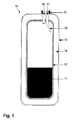
- FIGS. 1 to 12 First, various embodiments of a storage container 10 are shown - as well as their filling and discharging operations.
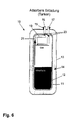
- the in the FIGS. 1 to 4 illustrated storage container 10 is formed in the form of a pressure vessel.
- the storage container 10 initially has an inner container 12 in which a sorption material 11 is located.
- the sorbent material 11 consists of a sorbent to which hydrogen is adsorbed.
- the inner container 12 is surrounded by an outer container 13, wherein between the two containers 12,13 an isolation region 14 is provided.
- the storage container 10 further has a connecting element 15, for example a flange, via which it can be connected to an external supply system.
- the storage container 10 has a first guide 16, which serves as a transport guide for the sorption material.
- a second guide 17 is provided, which serves as a gas guide. This gas guide 17 is formed in the present example as a nozzle 18.
- the aim of this embodiment is a mechanically simple as possible filling and discharging system to avoid complex designs and moving parts within the storage container 10.
- the basic idea is to transport the granular sorbent 11 through a gas stream at virtually any pressure up to about 40 bar.
- the tank system should basically have two openings / passages.
- the first passage 16 (transport guide) is provided with a proportionately large diameter in relation to the particle size of the sorption material (for example, a diameter equal to 50 times the particle size).
- the bushing 16 serves to transport the sorption material 11 both from the filling station to the tank system and also from the tank system to the filling station.
- the second passage 17 (gas guide) is in the form of a nozzle 18 and has a filter which retains penetrating Sorptionsmaterialpiety.
- This nozzle 18 is used when filling the tank system as a gas outlet.
- the hydrogen carrier gas required for this leaves the storage container 10 via the gas guide 17.
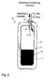
- a discharge FIG. 2
- existing sorbent material 11 is fluidized in the storage tank and through the transport guide 16 through the gas flow from transported to the storage container 10.
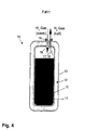
- driving FIG. 4
- Desorbed hydrogen is removed via the gas guide 17 and fed to the drive unit.
- heated hydrogen can be introduced via the transport guide 16 into the storage container 10.
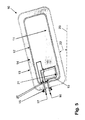
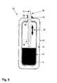
- the in the FIGS. 5 to 8 illustrated storage container 10 is also formed in the form of a pressure vessel.
- the storage container 10 in turn has an inner container 12 in which the sorption material 11 is located.
- the sorbent material 11 consists of a sorbent to which hydrogen is adsorbed.
- the inner container 12 is surrounded by an outer container 13, wherein between the two containers 12, 13 an isolation region 14 is provided.
- the storage container 10 further has a connecting element 15, for example a flange, via which it can be connected to an external supply system.
- the storage container 10 has a first guide 16, which serves as a transport guide for the sorbent material 11.
- a second guide 17 is provided, which serves as a gas guide.
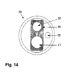
- the two guides 16, 17 are tubular and form a pipe loop 19. In the pipe loop 19, two rotatable flaps 20 are arranged to influence the flow within the pipe loop 19.
- the storage container 10 is characterized by a closed pipe loop 19 with the lowest possible internal flow resistance, which is interrupted at two points by 90 ° rotatable, flow-driven flaps 20.
- the aim of these flaps 20 is the deflection of the flow (sorption material + carrier gas) during the filling process.
- the first flap closes the passage through the pipe system and thereby causes the introduction of the sorption material 11 in the storage container ( FIG. 7 ).
- the carrier gas is conveyed via the second flap back into the pipe system and can be returned to the pump.
- a filter in front of the flap 20 prevents the discharge of sorption material 11.
- the carrier gas flows through the pipe loop 19 in the opposite direction.
- a constriction 21 of the pipe loop leads to the reduction of the static pressure in the pipe section and thereby to sucking sorption material 11 from the storage container 10.
- the sorption material 11 is dispersed in the carrier stream and discharged from the storage container 10.
- a slight inclination 22 of the storage container 10 and a favorable positioning of Vent districtil GmbHs 21 near the lowest point take over by using gravity on the inclined plane, the task of transporting the sorbent material 11 in the range of the suction.
- the inclination is with respect to a reference plane 23, which is formed in the present example as a horizontal plane. Whether the reference plane is a horizontal or vertical plane depends on the general orientation of the storage container 10. While driving ( FIG. 8 ) Desorbed hydrogen is removed via the gas guide 17 from the storage container 10.
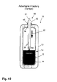
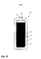
- storage container 10 is formed in the form of a pressure vessel.
- the storage container 10 in turn has an inner container 12 in which the sorption material 11 is located.
- the sorbent material 11 consists of a sorbent to which hydrogen is adsorbed.
- the inner container 12 is surrounded by an outer container 13, wherein between the two containers 12, 13 an isolation region 14 is provided.
- the storage container 10 further has a connecting element 15, for example a flange, via which it can be connected to an external supply system.
- the decoupling of the components required for the filling and discharge from the storage container 10 and thus a significant saving of weight and heat capacity.
- the task of supply and discharge of sorbent material 11 and carrier gas takes over a introduced through the filler neck 15 filling / discharge nozzle 30, which may also be designed flexibly in its end portion 34, which projects into the storage container 10 and characterized thereby in that the length of the nozzle 30 in the storage container 10 can be readjusted so that the sorption material 11 can be swirled up and removed as close as possible to the location.
- This Nachjustieriana is in the FIGS. 9 to 12 shown in the form of an arrow 33.
- the storage container 10 then has a single guide 24, through which the two other guides 31, 32 of the nozzle 10 can be passed. It is possible by the nachjustierbare, spatial proximity of the guides 31, 32 for Sorptionsmaterial 11 and the integration of a suction effect in the guides 31, 32, so that for the emptying of the storage container 10 is not necessarily the recirculation of hydrogen is necessary.
- FIG. 13 a scheme is shown, which first shows a mobile tank system 40, which should be arranged in a vehicle.
- the tank system 40 initially has a storage container 10, for example, in one of the in the FIGS. 1 to 12 illustrated variants may be formed.
- the storage container 10 is connected to a heat exchanger device 43, which in turn is connected via a line 45 to a drive unit 41 of the vehicle.
- the amount of hydrogen stored in the storage container 10 is made up of the adsorbed phase (H ads ), ie the hydrogen adsorbed on the sorbent, and the gas phase (H gas ), that is, the free volume of the tank 10 present hydrogen gas, together.
- H ads adsorbed phase
- H gas gas phase
- a state of equilibrium which depends on the adsorption properties of the sorbent is established.
- hydrogen required by the drive unit 41 of the vehicle can be taken directly from the gas phase. This hydrogen is available almost immediately in a determinable by the pressure prevailing in the storage tank 10 amount available.
- a volume flow of hydrogen required by the drive unit 41 of the vehicle can no longer be maintained (for example, a pressure of 2 bar).
- the corresponding values depend on the sorbent used.
- the supply of hydrogen can be ensured.
- This can be advantageously realized by already removed, cold hydrogen via a heat exchanger 43, which preferably uses the ambient heat, heated and returned to the storage tank 10, where the heat stored in the gas heat capacity is transferred to the sorbent material (recycling).
- the control of the heat input can be done for example by means of two positioned on the storage tank 10 solenoid valves that interrupt the line to an undesirable heat input to Example to avoid when not using the vehicle.
- the temperature in the tank system 40 can be increased without the use of an electric heater, and thus the hydrogen present in the adsorbed phase can be desorbed and used as needed.
- the storage container 10 can be supplied with sorption material 11 via a system 50 for providing a sorption material 11, in the present case a gas station.
- the storage container 10 can be connected to a charging device 51 during the filling process and unloading, which is illustrated by the arrows 54 and 55.
- the charging device may be a kind of dispenser of the filling station system 50.
- a data line 53 in the form of suitable interfaces can be present between the mobile tank system 40 and the provision system 50, via which, in particular, measured values can be exchanged which can advantageously assist the filling process and unloading process.
- the charging device 51 is connected via a connecting line 63 to a storage device 52, is stored in the already loaded sorbent material.
- the sorption material discharged via the charging device 41 can be supplied, for example, via a device 56 for quality control and a device 57 for the regeneration of a device 58 for loading a sorbent and / or sorbent material and subsequently, after loading, until further use in the storage container 52.
- This transport path of the sorbent material is in FIG. 13 represented by the arrows 59, 60, 61 and 62.
- the fully discharged sorbent or partially discharged sorbent material recovered from the mobile tank system 40 could be handled in the system 50 in two ways.
- Recovered, completely discharged sorbent or partially discharged sorbent material could first be assessed by quality control in facility 56. It could possibly be sorted out damaged or unusable particles.
- the sorbent and / or sorbent material could be regenerated (heat treated / annealed) in the device 57 to remove gaseous contaminants, for example from minor constituents of the gas used.
- gaseous contaminants for example from minor constituents of the gas used.
- the use of hydrogen of lower quality / purity is possible (for example, class purity class 3.0 instead of class 5.0).
- the sorbent / sorbent material can be cooled (77 K) and recharged with hydrogen and made available again at the pump. This is done in the device 58. It is energetically advantageous to cool and load the sorbent / sorbent material in discrete processes or continuously in succession. For example, staggering could be as follows: 0 ° C / -40 ° C / -80 ° C / -120 ° C / -160 ° C / -196 ° C. If appropriate, a coupling of the temperatures to known phase transitions, for. B. CO 2 solid ⁇ CO 2 gas (sublimation). Also, a variation of the loading pressure may help energy saving depending on the adsorption behavior of the materials.
- Another possibility is that recycled, partially discharged sorbent / sorbent material can be cooled and loaded without quality control or regeneration in order to be made available again at the pump.
- it can be ensured via a built-in tank system 40, readable and writable chip that in a meaningful cycle (for example, every fifth refueling operation), a quality control is performed regardless of the load condition.
- an interface 36 may be provided for an electrical data connection, which allows an exchange of information between the gas station 50 and the tank system 40 of the vehicle or the vehicle itself.
- the type of sorbent material, the loading state, the pressure, the temperature and the like could be transmitted.
- the tank system 40 of the vehicle are granular or precompacted, loose sorbent, which is partially loaded with hydrogen (The amount of adsorbed hydrogen is dependent on temperature and pressure in the tank system 40 and the amount and the adsorption properties of the sorbent material used.) , as well as unadsorbed, gaseous hydrogen (The amount of gaseous hydrogen can be determined by pressure, temperature and / or free volume present in the tank.).
- the filling nozzle 30 is first attached to the connecting flange 15 of the storage container 10. Subsequently, a determination of the residual amount of stored hydrogen by pressure and temperature measurement within the tank system 40 of the vehicle.
- the discharge of the sorption material located in the tank 10 of the vehicle takes place by blowing in hydrogen. Due to the special shape and position of the nozzle 18 (FIG. FIG. 1 ), the powdery sorption material 11 is fluidized and discharged by the gas flow through the outlet (gas guide 17).
- the pressure of this discharge circuit need not necessarily be 40 bar, but may for example be adapted to the residual pressure in the tank 10 to prevent adsorption or further desorption of the sorbent 11 during the discharge process.
- the tank system (ie, the empty storage tank 10) of the vehicle is cooled by injecting cold (77 K) hydrogen.
- cold (77 K) hydrogen gas is blown with adapted flow rate and flow from the gas station 50 via the provided for the gas inlet passage 16 into the storage container 10, wherein the heat flow dQ / dt from the pressure vessel (inner container 12 of the storage container 10) to the cold hydrogen gas Heat is dissipated, which is removed by the discharge of the now warmed up hydrogen gas through the designated passage 17 from the storage container 10 of the vehicle.
Landscapes
- Engineering & Computer Science (AREA)
- Chemical & Material Sciences (AREA)
- Organic Chemistry (AREA)
- Mechanical Engineering (AREA)
- Nanotechnology (AREA)
- General Engineering & Computer Science (AREA)
- Materials Engineering (AREA)
- Inorganic Chemistry (AREA)
- Combustion & Propulsion (AREA)
- Chemical Kinetics & Catalysis (AREA)
- Physics & Mathematics (AREA)
- Composite Materials (AREA)
- Condensed Matter Physics & Semiconductors (AREA)
- General Physics & Mathematics (AREA)
- Crystallography & Structural Chemistry (AREA)
- Filling Or Discharging Of Gas Storage Vessels (AREA)
- Hydrogen, Water And Hydrids (AREA)
- Carbon And Carbon Compounds (AREA)
- Solid-Sorbent Or Filter-Aiding Compositions (AREA)
Applications Claiming Priority (3)
| Application Number | Priority Date | Filing Date | Title |
|---|---|---|---|
| DE102007030140 | 2007-06-27 | ||
| DE102007033368A DE102007033368B4 (de) | 2007-06-27 | 2007-07-16 | Verfahren zum Bereitstellen eines Sorptionsmaterials für einen Speicherbehälter |
| EP08749130.4A EP2160232B1 (de) | 2007-06-27 | 2008-04-25 | Speicherbehälter für gasförmige krafstoffe und dessen anwendung |
Related Parent Applications (2)
| Application Number | Title | Priority Date | Filing Date |
|---|---|---|---|
| EP08749130.4 Division | 2008-04-25 | ||
| EP08749130.4A Division-Into EP2160232B1 (de) | 2007-06-27 | 2008-04-25 | Speicherbehälter für gasförmige krafstoffe und dessen anwendung |
Publications (1)
| Publication Number | Publication Date |
|---|---|
| EP2335801A1 true EP2335801A1 (de) | 2011-06-22 |
Family
ID=39670455
Family Applications (2)
| Application Number | Title | Priority Date | Filing Date |
|---|---|---|---|
| EP11002609A Withdrawn EP2335801A1 (de) | 2007-06-27 | 2008-04-25 | Speicherbehälter zum Speichern gasförmiges Kraftstoffes |
| EP08749130.4A Active EP2160232B1 (de) | 2007-06-27 | 2008-04-25 | Speicherbehälter für gasförmige krafstoffe und dessen anwendung |
Family Applications After (1)
| Application Number | Title | Priority Date | Filing Date |
|---|---|---|---|
| EP08749130.4A Active EP2160232B1 (de) | 2007-06-27 | 2008-04-25 | Speicherbehälter für gasförmige krafstoffe und dessen anwendung |
Country Status (5)
| Country | Link |
|---|---|
| US (1) | US20110127174A1 (enExample) |
| EP (2) | EP2335801A1 (enExample) |
| JP (1) | JP5229674B2 (enExample) |
| DE (2) | DE202007009992U1 (enExample) |
| WO (1) | WO2009000357A2 (enExample) |
Families Citing this family (18)
| Publication number | Priority date | Publication date | Assignee | Title |
|---|---|---|---|---|
| DE102009000508A1 (de) * | 2008-07-29 | 2010-02-04 | Robert Bosch Gmbh | Speicherbehälter und Verfahren zum verlustreduzierten Speichern eines Brennstoffs |
| DE102008040954A1 (de) * | 2008-08-04 | 2010-02-11 | Robert Bosch Gmbh | Speicher für ein Medium, insbesondere für Ammoniak |
| WO2011103627A1 (en) | 2010-02-24 | 2011-09-01 | Hydrexia Pty Ltd | Hydrogen release system |
| JP5703164B2 (ja) * | 2011-07-29 | 2015-04-15 | Jx日鉱日石エネルギー株式会社 | 水素貯蔵用複合容器及び水素充填方法 |
| TWI583445B (zh) | 2012-04-13 | 2017-05-21 | 恩特葛瑞斯股份有限公司 | 乙炔的儲存與安定化 |
| WO2015048493A1 (en) * | 2013-09-27 | 2015-04-02 | Basf Corporation | Gas filtering in adsorbed gas systems |
| US20150090611A1 (en) * | 2013-09-27 | 2015-04-02 | Basf Corporation | Pressure release device for adsorbed gas systems |
| DE102014210902B4 (de) * | 2014-06-06 | 2023-12-07 | Bayerische Motoren Werke Aktiengesellschaft | Drucktank |
| WO2016149049A1 (en) * | 2015-03-13 | 2016-09-22 | Cenergy Solutions | Increased storage capacity of gas in pressure vessels |
| US11141784B2 (en) | 2015-07-23 | 2021-10-12 | Hydrexia Pty Ltd. | Mg-based alloy for hydrogen storage |
| FR3056263B1 (fr) * | 2016-09-21 | 2018-09-28 | Commissariat A L'energie Atomique Et Aux Energies Alternatives | Compresseur d'hydrogene a hydrure metallique |
| GB201719399D0 (en) * | 2017-11-22 | 2018-01-03 | Bennamann Services Ltd | Liquid methane storage and fuel delivery system |
| US10960995B2 (en) * | 2019-07-24 | 2021-03-30 | Ford Global Technologies, Llc | Methods and apparatuses for filling adsorbent powder in a hydrogen or natural gas tank |
| CN112875047A (zh) * | 2021-01-12 | 2021-06-01 | 辽宁科技学院 | 一种应用于化学药物的成分检测试剂盒 |
| FR3123707B1 (fr) * | 2021-06-08 | 2024-04-05 | Absolut System | Procédé et système de pressurisation d’hydrogène gazeux |
| US20240288124A1 (en) * | 2021-07-26 | 2024-08-29 | Korea Institute Of Machinery & Materials | High pressure gas charging system and high pressure gas charging method using the same |
| CN115387975B (zh) * | 2022-08-30 | 2024-01-26 | 兰州空间技术物理研究所 | 一种用于电推进的新型碘工质储罐 |
| GB2631952A (en) * | 2023-07-18 | 2025-01-22 | Phinia Delphi Luxembourg Sarl | Fuel-management system for a hydrogen vehicle |
Citations (11)
| Publication number | Priority date | Publication date | Assignee | Title |
|---|---|---|---|---|
| DE2615630A1 (de) | 1975-04-21 | 1976-11-04 | Billings Energy Res | Vorrichtung und verfahren zur hydridspeicherung und zum waermeaustausch |
| EP0444995A1 (fr) * | 1990-03-02 | 1991-09-04 | L'air Liquide, Societe Anonyme Pour L'etude Et L'exploitation Des Procedes Georges Claude | Enceinte et installation d'adsorption pour séparation des mélanges gazeux |
| EP0591840A1 (en) * | 1992-10-06 | 1994-04-13 | Air Products And Chemicals, Inc. | Apparatus for supplying high purity fluid |
| US5985008A (en) * | 1997-05-20 | 1999-11-16 | Advanced Technology Materials, Inc. | Sorbent-based fluid storage and dispensing system with high efficiency sorbent medium |
| US6309446B1 (en) * | 1997-02-17 | 2001-10-30 | Kanebo, Ltd. | Activated carbon for adsorptive storage of gaseous compound |
| DE202004017036U1 (de) | 2003-11-05 | 2005-01-13 | Future Camp Gmbh | Speicherbehälter zum Speichern eines Mediums |
| DE102005023036A1 (de) | 2005-05-13 | 2006-11-16 | Deutsches Zentrum für Luft- und Raumfahrt e.V. | Wasserstoffspeicher und Verfahren zur Wasserstoffspeicherung |
| DE202006003602U1 (de) * | 2005-12-19 | 2007-02-15 | BLüCHER GMBH | Sorptionsspeichereinheit für Gase |
| US20070068389A1 (en) * | 2005-09-26 | 2007-03-29 | Yaghi Omar M | Metal-organic frameworks with exceptionally high capacity for storage of carbon dioxide at room-temperature |
| DE102005053300A1 (de) * | 2005-11-09 | 2007-05-10 | Romold Gmbh | Verfahren zur Eliminierung von Schwefelwasserstoff und Gerüchen aus Abwassersystemen |
| EP1790904A1 (en) * | 2005-11-29 | 2007-05-30 | HONDA MOTOR CO., Ltd. | Apparatus for and method of filling hydrogen tank with hydrogen |
Family Cites Families (17)
| Publication number | Priority date | Publication date | Assignee | Title |
|---|---|---|---|---|
| US3977849A (en) * | 1973-01-29 | 1976-08-31 | U.S. Philips Corporation | Sorption pump |
| NL7301204A (enExample) * | 1973-01-29 | 1974-07-31 | ||
| FR2272272B1 (enExample) * | 1974-05-24 | 1979-05-25 | Peugeot & Renault | |
| US4967814A (en) * | 1988-09-19 | 1990-11-06 | Westvaco Corporation | Apparatus for filling high pressure gas storage bottles with powdered activated carbon |
| DE69409907T2 (de) * | 1993-10-25 | 1999-01-21 | Westvaco Corp., New York, N.Y. | Hochmicroporöse Kohlenstoffe und Verfahren zu ihrer Herstellung |
| GB9522476D0 (en) * | 1995-11-02 | 1996-01-03 | Boc Group Plc | Method and vessel for the storage of gas |
| US5858067A (en) | 1996-05-20 | 1999-01-12 | Advanced Technology Materials, Inc. | Ex situ degassing and sorbate loading system for manufacture of sorbent-based fluid storage and dispensing apparatus |
| DE19703749A1 (de) * | 1997-01-24 | 1998-07-30 | Holger Dyja | Verfahren zur Freisetzung von Wasserstoff aus einem Speichermedium |
| JP2001113116A (ja) * | 1999-10-19 | 2001-04-24 | Fujitsu Ltd | 排気処理方法及び排気処理装置 |
| DE10021289A1 (de) | 2000-05-02 | 2001-11-08 | Ludwig Boelkow Stiftung | Tankanlage für aus kleinen bis kleinsten Festkörpern bestehendes, mit einem brennbaren Gas beladbares Schüttgut und einer Einrichtung zum Entladen des Schüttgutes |
| US6743278B1 (en) * | 2002-12-10 | 2004-06-01 | Advanced Technology Materials, Inc. | Gas storage and dispensing system with monolithic carbon adsorbent |
| US7124790B2 (en) | 2004-06-28 | 2006-10-24 | General Electric Company | System and method for storing and discharging hydrogen |
| JP2006083898A (ja) * | 2004-09-14 | 2006-03-30 | Honda Motor Co Ltd | 水素貯蔵タンク |
| DE102005004592B4 (de) * | 2005-02-01 | 2018-06-28 | Bayerische Motoren Werke Aktiengesellschaft | Speicher und/oder Druckerhöhungseinrichtung für Wasserstoff |
| US20060283864A1 (en) * | 2005-02-10 | 2006-12-21 | Angstrom Power | Shipping container and method of use |
| DE102006010636A1 (de) * | 2005-12-19 | 2007-06-21 | BLüCHER GMBH | Sorptionsspeichereinheit für Gase |
| DE202006016898U1 (de) | 2006-10-12 | 2007-11-22 | BLüCHER GMBH | Hochleistungsadsorbentien auf der Basis von Aktivkohle mit hoher Mikroporosität |
-
2007
- 2007-07-16 DE DE202007009992U patent/DE202007009992U1/de not_active Expired - Lifetime
- 2007-07-16 DE DE102007063630A patent/DE102007063630B4/de not_active Expired - Fee Related
-
2008
- 2008-04-25 EP EP11002609A patent/EP2335801A1/de not_active Withdrawn
- 2008-04-25 JP JP2010513686A patent/JP5229674B2/ja not_active Expired - Fee Related
- 2008-04-25 WO PCT/EP2008/003350 patent/WO2009000357A2/de not_active Ceased
- 2008-04-25 US US12/666,425 patent/US20110127174A1/en not_active Abandoned
- 2008-04-25 EP EP08749130.4A patent/EP2160232B1/de active Active
Patent Citations (12)
| Publication number | Priority date | Publication date | Assignee | Title |
|---|---|---|---|---|
| DE2615630A1 (de) | 1975-04-21 | 1976-11-04 | Billings Energy Res | Vorrichtung und verfahren zur hydridspeicherung und zum waermeaustausch |
| EP0444995A1 (fr) * | 1990-03-02 | 1991-09-04 | L'air Liquide, Societe Anonyme Pour L'etude Et L'exploitation Des Procedes Georges Claude | Enceinte et installation d'adsorption pour séparation des mélanges gazeux |
| EP0591840A1 (en) * | 1992-10-06 | 1994-04-13 | Air Products And Chemicals, Inc. | Apparatus for supplying high purity fluid |
| US6309446B1 (en) * | 1997-02-17 | 2001-10-30 | Kanebo, Ltd. | Activated carbon for adsorptive storage of gaseous compound |
| US5985008A (en) * | 1997-05-20 | 1999-11-16 | Advanced Technology Materials, Inc. | Sorbent-based fluid storage and dispensing system with high efficiency sorbent medium |
| DE202004017036U1 (de) | 2003-11-05 | 2005-01-13 | Future Camp Gmbh | Speicherbehälter zum Speichern eines Mediums |
| WO2005044454A2 (de) | 2003-11-05 | 2005-05-19 | Future Camp Gmbh | Speichersystem zum speichern eines mediums sowie verfahren zum beladen/entladen eines speichersystems mit einem speichermedium |
| DE102005023036A1 (de) | 2005-05-13 | 2006-11-16 | Deutsches Zentrum für Luft- und Raumfahrt e.V. | Wasserstoffspeicher und Verfahren zur Wasserstoffspeicherung |
| US20070068389A1 (en) * | 2005-09-26 | 2007-03-29 | Yaghi Omar M | Metal-organic frameworks with exceptionally high capacity for storage of carbon dioxide at room-temperature |
| DE102005053300A1 (de) * | 2005-11-09 | 2007-05-10 | Romold Gmbh | Verfahren zur Eliminierung von Schwefelwasserstoff und Gerüchen aus Abwassersystemen |
| EP1790904A1 (en) * | 2005-11-29 | 2007-05-30 | HONDA MOTOR CO., Ltd. | Apparatus for and method of filling hydrogen tank with hydrogen |
| DE202006003602U1 (de) * | 2005-12-19 | 2007-02-15 | BLüCHER GMBH | Sorptionsspeichereinheit für Gase |
Non-Patent Citations (6)
| Title |
|---|
| "Operating Manual, OM, 05061, Quantachrome Instruments", 2004, article "Quantachrome Instruments, AUTOSORB-1, AS 1 WinVersion 1,50", pages: 71 FF |
| "Testmethoden für Aktivkohlen", November 1986, CONSEIL EUROPEEN DES FEDERATIONS DES 1'INDUSTRIE CHIMIQUE, article "Mechanische Härte", pages: 18 - 19 |
| L. GURVICH, J. PHYS, CHEM. SOC, RUSS., vol. 47, 1915, pages 805 |
| R. W. MAGEE: "Meeting of the Rubber Division of the American Chem. Soc", October 1994, article "Evaluation of the External Surface Area of Carbon Black by Nitrogen Adsorption" |
| STICHWORT: "Römpp Chemielexikon", GEORG THIEME VERLAG, article "BET-Methode" |
| Z. ANAL. CHEM., vol. 238, 1968, pages 187 - 193 |
Also Published As
| Publication number | Publication date |
|---|---|
| EP2160232A2 (de) | 2010-03-10 |
| JP2010531961A (ja) | 2010-09-30 |
| WO2009000357A3 (de) | 2009-06-11 |
| DE102007063630A1 (de) | 2009-01-08 |
| JP5229674B2 (ja) | 2013-07-03 |
| EP2160232B1 (de) | 2014-10-01 |
| WO2009000357A2 (de) | 2008-12-31 |
| DE202007009992U1 (de) | 2008-07-31 |
| DE102007063630B4 (de) | 2010-02-04 |
| US20110127174A1 (en) | 2011-06-02 |
Similar Documents
| Publication | Publication Date | Title |
|---|---|---|
| EP2160232B1 (de) | Speicherbehälter für gasförmige krafstoffe und dessen anwendung | |
| DE102007005366B4 (de) | Vorrichtung für optimale Adsorption und Desorption von Gasen unter Verwendung von hochporösen Gasspeichermaterialien | |
| WO2003064030A1 (de) | Verfahren zum speichern, zur aufnahme und abgabe von gasen unter verwendung neuartiger gerüstmaterialien | |
| WO2007124825A1 (de) | Wasserstoffspeicher und verfahren zum befüllen eines wasserstoffspeichers | |
| WO2008017356A1 (de) | Monolithische materialien für gasspeicher | |
| US5985008A (en) | Sorbent-based fluid storage and dispensing system with high efficiency sorbent medium | |
| DE10110169A1 (de) | Wasserstoff-Speichereinheit | |
| DE102008011189A1 (de) | Polykondensationsnetzwerke zur Gasspeicherung | |
| DE3687256T2 (de) | Verfahren und mittel zur gasadsorption. | |
| DE102014104185A1 (de) | Verfahren zum Vergrößern der Speicherkapazität eines Erdgastanks | |
| WO2023001422A1 (de) | Verfahren zum betrieb einer elektrolyseanlage und elektrolyseanlage | |
| DE102014104182A1 (de) | Verfahren zum Speichern und Verwenden von Erdgas in einem Fahrzeug | |
| CN106999908A (zh) | 具有改善的热容量的吸附剂混合物 | |
| DE102008023481B4 (de) | Wärmeleitfähige Komposit-Adsorbentien sowie Verfahren zu deren Herstellung und deren Verwendung | |
| DE102007033368B4 (de) | Verfahren zum Bereitstellen eines Sorptionsmaterials für einen Speicherbehälter | |
| EP0463143B1 (de) | Filtermaterial für kraftfahrzeuge | |
| EP2309166A1 (de) | Behälter und Verfahren zum Speichern von Gas mit einem in einem Metallschäum zusammengefügte Adsorbent | |
| DE10011223A1 (de) | Sphärische Hochleistungsadsorbenzien mit Mikrostruktur | |
| EP2558184A1 (de) | Vorrichtung zur adsorptionsbehandlung eines fluids oder fluidstroms | |
| DE2840265C3 (de) | Granulat aus einer FeTiMn-Legierung zur Speicherung von Wasserstoff und/oder Deuterium in Druckgasflaschen | |
| JP2012189219A (ja) | 高能力の物理的吸着剤からなる流体貯蔵ならびに搬送システム | |
| DE102005023036A1 (de) | Wasserstoffspeicher und Verfahren zur Wasserstoffspeicherung | |
| Abdel Moniem et al. | Kinetic and Isotherm Models For Metal Removal Using Modified Graphene | |
| DE4319895C2 (de) | Verfahren zur Reinigung von lösemittelhaltiger Abluft durch Adsorberharze | |
| DE10007544A1 (de) | Festkörper mit Poren- bzw. Kanalstrukturen zum Speichern von Gasen und Verfahren zum Herstellen der Festkörper zur Verwendung in Speichereinrichtungen |
Legal Events
| Date | Code | Title | Description |
|---|---|---|---|
| PUAI | Public reference made under article 153(3) epc to a published international application that has entered the european phase |
Free format text: ORIGINAL CODE: 0009012 |
|
| AC | Divisional application: reference to earlier application |
Ref document number: 2160232 Country of ref document: EP Kind code of ref document: P |
|
| AK | Designated contracting states |
Kind code of ref document: A1 Designated state(s): AT BE BG CH CY CZ DE DK EE ES FI FR GB GR HR HU IE IS IT LI LT LU LV MC MT NL NO PL PT RO SE SI SK TR |
|
| AX | Request for extension of the european patent |
Extension state: AL BA MK RS |
|
| 17P | Request for examination filed |
Effective date: 20110616 |
|
| 17Q | First examination report despatched |
Effective date: 20120612 |
|
| STAA | Information on the status of an ep patent application or granted ep patent |
Free format text: STATUS: THE APPLICATION IS DEEMED TO BE WITHDRAWN |
|
| 18D | Application deemed to be withdrawn |
Effective date: 20121023 |