EP2335527A1 - Bettrahmen mit nach oben klappbarem Schlafelement - Google Patents
Bettrahmen mit nach oben klappbarem Schlafelement Download PDFInfo
- Publication number
- EP2335527A1 EP2335527A1 EP10190954A EP10190954A EP2335527A1 EP 2335527 A1 EP2335527 A1 EP 2335527A1 EP 10190954 A EP10190954 A EP 10190954A EP 10190954 A EP10190954 A EP 10190954A EP 2335527 A1 EP2335527 A1 EP 2335527A1
- Authority
- EP
- European Patent Office
- Prior art keywords
- support
- panels
- longitudinal
- support portion
- bed base
- Prior art date
- Legal status (The legal status is an assumption and is not a legal conclusion. Google has not performed a legal analysis and makes no representation as to the accuracy of the status listed.)
- Granted
Links
- 210000003127 knee Anatomy 0.000 claims abstract description 71
- 239000011248 coating agent Substances 0.000 claims description 37
- 238000000576 coating method Methods 0.000 claims description 37
- 210000001217 buttock Anatomy 0.000 claims description 14
- 239000000725 suspension Substances 0.000 claims description 8
- 239000000835 fiber Substances 0.000 claims description 7
- 239000006260 foam Substances 0.000 claims description 7
- 210000002414 leg Anatomy 0.000 claims description 7
- 230000007935 neutral effect Effects 0.000 claims description 6
- 230000000873 masking effect Effects 0.000 claims description 5
- 239000011152 fibreglass Substances 0.000 claims description 4
- 238000005452 bending Methods 0.000 description 6
- 239000002023 wood Substances 0.000 description 3
- 238000006073 displacement reaction Methods 0.000 description 2
- 238000011084 recovery Methods 0.000 description 2
- 210000000689 upper leg Anatomy 0.000 description 2
- 241000195940 Bryophyta Species 0.000 description 1
- 208000031968 Cadaver Diseases 0.000 description 1
- OKTJSMMVPCPJKN-UHFFFAOYSA-N Carbon Chemical compound [C] OKTJSMMVPCPJKN-UHFFFAOYSA-N 0.000 description 1
- 241000735470 Juncus Species 0.000 description 1
- 229910000639 Spring steel Inorganic materials 0.000 description 1
- 229910052799 carbon Inorganic materials 0.000 description 1
- 230000001627 detrimental effect Effects 0.000 description 1
- 238000005553 drilling Methods 0.000 description 1
- 230000000694 effects Effects 0.000 description 1
- 239000013013 elastic material Substances 0.000 description 1
- 239000003365 glass fiber Substances 0.000 description 1
- 235000011929 mousse Nutrition 0.000 description 1
Images


Classifications
-
- A—HUMAN NECESSITIES
- A47—FURNITURE; DOMESTIC ARTICLES OR APPLIANCES; COFFEE MILLS; SPICE MILLS; SUCTION CLEANERS IN GENERAL
- A47C—CHAIRS; SOFAS; BEDS
- A47C20/00—Head -, foot -, or like rests for beds, sofas or the like
- A47C20/04—Head -, foot -, or like rests for beds, sofas or the like with adjustable inclination
Definitions
- the invention relates generally sommieres.
- the invention more particularly relates to a bed base comprising a frame frame, and a sleeping surface for supporting at least the body of a person.
- Said sleeping surface has at least a central support portion of the gluteal, fixedly mounted relative to the frame, on either side of which extend respectively a support portion of the knees and a supporting portion of the back.
- Said knee support and back support portions are each adapted to be moved between a lowered position on the frame and a raised position relative to the frame.
- the sleeping surface does not allow to marry in a regular manner the profile of the mattress and therefore the body of the extended person, through the mattress, on said sleeping surface.
- Such a design of the sleeping surface is detrimental to the comfort of the person.
- An object of the present invention is to provide a bed base for which the sleeping surface is liftable while maintaining in the raised state a profile in the form of a regular line, that is to say without broken pan, so as to marry correctly the profile of the body of the person lying on the sleeping surface via the mattress.
- Another object of the present invention is to provide a bed base with a lifting surface whose profile has a regular curve line regardless of its configuration, raised or lowered, while providing good support for the body parts of the person, especially at the back and knees.
- each longitudinal blade of flexible connection plays the role of a spinal column connecting the rigid panels that form the vertebrae of said column.
- the or bendable longitudinal blades which connect the corresponding rigid panels together, form flexible joints without moving rigid parts, this which allows them to present a regular continuous curvature when the rigid panels are moved relative to each other.
- the presence of the or bendable blades between the panels avoids the appearance of broken sections at the curve formed by the profile of the sleeping surface in the raised position of the support portions of the knees and / or back. Indeed, the relative displacement of the rigid panels between them is accompanied by the bending deformation of the bendable blades, about an axis parallel to the plane of the frame and orthogonal to the longitudinal axis of the frame, which allows the surface of Sleeping the box to marry at best the curvature of the mattress and thus the morphology of the person lying on the mattress.
- the sleeping surface has a regular profile which corresponds to a curve whose derivative of order 1 is continuous, allowing to the sleeping surface to effectively marry the profile of the mattress and the person to enhance comfort.
- the sleeping surface in the form of rigid panels, the sleeping surface also provides firm support for the different parts of the body of the person lying on the sleeping surface, both in the lowered and raised position, while allowing the sleeping surface to have different lines of regular curvature depending on the morphology of the extended person and his position on the sleeping surface.
- the design of the support portions of the back and knees in the form of series of elements formed of panels provides for each of these support portions, a lower surface, respectively upper, formed by the lower surfaces, respectively upper, panels that form said support portion, which is close to the neutral fiber of said support portion
- the panels have a small thickness compared to their width and length dimensions.
- the lower faces, respectively upper, of the panels that make up said portions deviate slightly from each other, which reduces the appearance broken flanks along the sleeping surface.
- the panels have a thickness less than or equal to 5 times the width of the panel.
- the width of a panel corresponds to the size of the panel taken along the neutral fiber of the sleeping surface (please complete).
- the coating surface also comprises at least one so-called end panel, extending the a knee support portion for forming a foot support portion, said end panel being connected to the other panels of the sleeping surface by said at least one longitudinal bendable connecting blade which connects at least the panels of said support portion of the knees at the central portion fixed gluteal support.
- said back support portion and said knee support portion are each connected to the central gluteal support portion by at least two, preferably four, longitudinally displaceable connecting blades parallel to one another and arranged at a spacing from one another. on the other in the direction of the width of the sleeping surface.
- At least one of the longitudinal strips of flexible connection is attached to at least a portion, preferably each, of said panels, preferably on the underside side of the panels, preferably by screwing.
- at least one of the longitudinal strips of bendable connection is housed at least partially in the thickness of said panels, preferably near the neutral fiber of said panels.
- At least a portion of the panels which form said knee and back support portions are of width, taken along the longitudinal line of the sleeping surface, less than the width of the fixed central portion. gluteal support.
- the or at least one of the longitudinal strips of flexible connection which connects the knee support portion to the fixed central support portion of the gluteal shape with the or at least one of the longitudinal blades of flexible connection which connects the support portion of the back to the central portion fixed gluteal support a piece in one piece.
- the or at least one of the connecting blades that connects the portion of back support to the central fixed support portion of the buttocks, and the or at least one of the connecting blades that connects the knee support portion to the central fixed support portion of the buttocks form separate pieces that s' extend, disjoint or not, along the coating surface, in the longitudinal extension of one another or being shifted transversely relative to each other.
- the sleeping surface also comprises a so-called end panel, extending the support portion of the knees to form a foot support portion
- each longitudinal edge of the coating surface is coated with an elongated elastically deformable element, called rod, for masking said longitudinal edge.
- Such a ring provides a regular profile visually on each side of the sleeping surface, regardless of the curvature taken by the sleeping surface.
- Said ring masks any apparent gaps between the panels that would be visible along the sides of the sleeping surface in the absence of said ring.
- the application of a ring on each of the lateral edges of the panels which form the coating surface is particularly advantageous for obtaining a line of regular curvature of the coating surface, because the panels being of small thickness, compared to their dimensions width and length, the upper and lower longitudinal edges of the rod are close to the average line or neutral fiber formed by said or bendable blades that connect the panels together, which limits the risk of tearing of the rod, during the curvature changes that the sleeping surface undergoes.
- the coating surface carries a series of suspension elements, called strands, each having an elongate foam body disposed on the panels transversely to the longitudinal line of the coating surface, a stiffening blade, such as a fiberglass blade, being inserted into the foam body of each of said flanges.
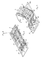
- the invention relates to a bed base, including bed, comprising a framework 10 forming a frame, and a sleeping surface for supporting at least the body of a person, via a mattress.
- the framework 10 forming frame is composed mainly of two longitudinal members interconnected by two sleepers and is intended to extend in a plane parallel to the ground plane, substantially horizontally.
- Said sleeping surface has at least one central support portion 20 of the buttocks, mounted fixed relative to the frame 10, on either side of which extend respectively a support portion of the knees 11 and a support portion of the back 14
- the central panel 20 is attached to a beam forming the middle cross member of the frame.
- Said knee support and back support portions 14 are each able to be displaced between, on the one hand, a lowered position on the frame 10, in which said support portions 11, 14 extend parallel to, and in the extension of, the central portion 20, applied to the upper surface of the frame 10, and, on the other hand, a raised position relative to the frame 10, wherein said support portions 11, 14 are at least partially spaced apart the upper surface of the frame 10 to follow the curve of the knees and the back of the person in a sitting position thereof along the sleeping surface.
- At least the knee support portion 11 and the support portion of the back 14 are each formed of a series of rigid panels 2, 21, preferably made of wood, connected to each other and to said fixed central portion 20 gluteal support by at least one longitudinal blade of flexible connection 3, 3A, 3B which extends substantially parallel to the longitudinal line of the coating surface.
- the or each longitudinal bendable connecting blade is configured to allow panels forming the series of panels forming the portion of the knees and the support portion of the back, to be pivotally displaced relative to each other by bending, or bending of the or each bendable blade, about an axis perpendicular to the longitudinal axis of said blade.
- the or each bendable connecting blade allows to accompany, by bending of said blade, the pivotal movements of the panels relative to each other.
- the part of the sleeping surface which comprises at least the knee support portion 11, the central portion 20, and the support portion of the back 14, is formed of a succession of rigid panels 2, 20, 21, 23, 24, preferably of wood, arranged side by side.
- Each panel 2, 20, 21, 22, 23, 24 of the succession of panels arranged side by side is selected of sufficient length to extend from one spar to the other of the frame.
- the longitudinal line of the coating surface corresponds to the average line of the assembly formed by the succession of said rigid panels 2, 20, 21, 23, 24.
- Each bendable connecting strip extends along the longitudinal line of the surface of sleeping, namely the longitudinal axis of the frame in the lowered state of the sleeping surface against the frame.
- the panels are spaced apart from each other, preferably at a distance of the order of 1 cm.
- Said panels which form the sleeping surface are elongate panels distributed along the longitudinal line of the bed base and which extend transversely with respect to said longitudinal line, that is to say transversely to the or each longitudinal strip.
- the panels that make up the knee support portion 11 and the panels that make up the support portion of the back 14 are movable relative to each other by pivoting about an axis orthogonal to the average line of the sleeping surface.
- these panels are movable relative to each other by virtue of the possibility of bending the connecting blade or blades which connect them to each other.
- Said panels which form the support portions of the knees 11 and the back 14 are free of articulated mechanical links, formed of rigid moving parts, with the adjacent panel or panels which are part of the same support portion.
- Such a bed base design allows the luffable sleeping surface to have a continuous line profile of regular curvature in the raised state of at least a portion of the sleeping surface, particularly at the raised portion of the bedding portion. knee support and / or back support portion.
- the rigid panels furthermore provide good support for the various parts of the body of the elongated person, and the flexibility of the connecting elements formed by the flexible connecting strips makes it possible to obtain a regular continuous curvature, that is to say ergonomically speaking, the sleeping surface to marry effectively the morphology of the person.
- the main sleeping part 1 also includes a so-called end panel 23, extending the support portion of the knees 11 to form a foot support portion. Said end panel 23 is connected to the other panels 2, 20, 21, 24 of the main coating part 1 by said at least one longitudinal bendable connecting blade 3, 3A which connects the portion of knee support 11 to the central fixed portion 20.
- the support portion of the back 14 comprises a panel 24 forming the end of the sleeping surface opposite the end formed by the foot support panel 23. Said panel 24 can support the upper back, especially the shoulders of the person .
- the sleeping surface also comprises a head support portion 4 which is composed of two elements, namely a base 41 connected by hinges to the support panel 24 of the upper back, and a portion 42 forming a telescopic headrest mounted on the base 41, that is to say movable to longitudinally spaced relative to the base 41 with the aid of a motor.
- the panel 41 is of greater width than the panels 2 which allow to obtain the pronounced curvature of the support portions of the knees 11 and back 14.
- the headrest is equipped with a reading lamp 8.
- the bendable connecting strips 3, 3A, 3B connect between them the end panel 23 foot support and the end panel 24 located at the upper back, and the intermediate panels 2, 21, 20.
- the set of panels that form the knee support portion 11 and all the panels that form the support portion of the back 14 are each connected to the fixed central portion 20 buttock support by at least two, preferably four, longitudinally flexible connecting strips 3, 3A, 3B parallel to each other and arranged spaced from each other in the width direction of the coating surface, to ensure a good recovery of efforts following the width of said sleeping plane.
- said blades are formed of two central connecting blades 3A, 3B and two lateral connecting blades 3 which extend along and near the longitudinal edges of the coating surface.
- Each lateral connection blade 3 which connects the portion of knee support 11 to the fixed central portion 20 gluteal support forms with a lateral connecting blade 3 which connects the support portion of the back 14 to the fixed central portion 20 gluteal support, a piece in one piece.
- each blade 3B which connects the support portion of the back 14 to the central fixed support portion 20 of the buttocks is of greater width than the or at least one of the blades link, here each blade 3A, which connects the support portion of the knees 11 to the central fixed portion 20 support of the buttocks, to provide a stiffness of the upper sleeping surface at the support areas of the back and the head in relation to the support zones of the feet and knees.
- the support portion of the knees 11 and the supporting portion of the back 14 are each connected to the central fixed portion 20 support of the buttocks by two central blades 3A, 3B.
- Each blade 3A which connects the support portion of the knees 11 to the central fixed portion 20 is disposed in the extension of a blade 3B which connects the support portion of the back 14 to the central fixed portion 20.
- the connecting strips 3, 3A, 3B are preferably attached to the underside panels of said panels to obtain a better mechanical behavior of said blades. Indeed, in this configuration, the blades 3, 3A, 3B are pushed against the panels during the recovery of the support portions of the knees and / or back.
- each longitudinal flexible bending strip 3, 3A, 3B is housed at least partially in the thickness of said panels 2, 20, 21, 23, 24, so that the blades are located near the neutral fiber of the panels so that to allow a good deformation of the sleeping surface, with a necessary gap between the panels which remains limited.
- each longitudinal blade extends in the thickness of said rigid panels by means of a groove formed in the bottom surface of said rigid panels.
- the thickness of the panels is preferably greater than or equal to 19 mm.
- the bendable connecting blades 3, 3A, 3B are made, in the example illustrated in the figures, of glass fibers and, preferably, cross-fibers to allow a good drilling of said blades for their screwing into the panels.
- the bendable longitudinal blades may also be spring steel blades, or carbon blades.
- the fixing of the blades 3, 3A, 3B in particular by screwing, to the panels avoids slipping of the blades 3, 3A, 3B relative to the panels during relative movements of the panels together.
- the coating surface is formed of panels of smaller width, taken along the longitudinal line of the coating surface, relative to the panels of other areas.
- the support portion of the knees and the support portion of the lower back are composed of panels 2 of smaller width than the support end panels of the feet 23 and support end of the upper back 24.
- knee support also includes a panel 21 wider than said panels 2 since said panel 21 is intended to support the thighs. Said panel 21 is connected to the central gluteal support panel by a panel 2 of smaller width to ensure sufficient curvature of the sleeping surface in the area between the buttocks and thighs.
- the central fixed portion of the coating surface, formed here by the panel 20, is of width at least equal to twice the width of the panels 2 of smaller width composing the support portions of the knees 11 and the back 14.
- the bed base is equipped with two systems of lifting 5 support portions of the feet and knees as described below and lifting members 6 of the headrest portion.
- the lifting of the headrest part also makes it possible to raise the support portion of the back 14.
- the two lifting systems 5 intended for lifting the knee and foot support portions are mounted at a distance from each other. one of the other in the direction of the width of the frame on a transverse bar connecting the two longitudinal members of the frame between them and pivotally mounted relative to the longitudinal members of the frame.
- This crossbar is equipped with a shoe for receiving an engine for pivoting the lifting systems 5, these lifting systems being in parallel arrangement.
- the lifting members 6 of the headrest portion are mounted spaced apart from each other in the direction of the width of the frame on a transverse bar connecting the two side members of the frame between them and pivotally mounted relative to each other. to frame rails. Said lifting members 6 are conventional lifting means.
- Each lifting system 5 support portions of the feet 23 and knees 11, is formed by an arm 50, one end of which is coupled to said crossbar, itself pivotally mounted relative to said frame.
- Said arm 50 has at or near its opposite end, a first leg 51 coupled to the support portion 23 of the feet, and a second leg 52 coupled to the portion 11 for supporting the knees.
- Said first and second branches 51, 52 are interconnected by a pivot connection axis parallel to the pivot axis of said arm 50.
- the two branches 51, 52 form a V between them.
- each lifting member 5 At the beginning of the displacement stroke of each lifting member 5 from the lowered position to the raised position, the support portions of the feet and knees are substantially flat and parallel to each other until they reach a given angle of rotation of each member. 5 for which the support portions of the feet and knees has a curved profile of concavity turned towards the ground, particularly at the knees, allowing to ensure a good support of the knees and to marry well the profile of the knees of the person in sitting position of this one along the bedstead.
- Each longitudinal edge of the coating surface is coated with an elongated elastically deformable element 7, called a rod, preferably made of rubber, in order to mask the lateral edge of the rigid panels and the longitudinal connecting strips which connect said rigid panels to one another.
- the flexible rod does not support the mattress but can hide the longitudinal edges of the sleeping surface which follows the curvature.
- Each ring preferably extends over the entire length of the coating surface.
- each ring has a generally U-shaped cross-section so that it can be easily interlocked with the longitudinal edges of the coating surface.
- Each branch of the U also has, on the outer side of the U, a clearance 71 to facilitate the attachment by stapling of the U-branch portion to the corresponding longitudinal edge of the coating surface.
- said ring 7 has, for each branch of the U, a masking lip 72 capable of covering the clearance 71 of said branch of the U to mask the staple or staples in the stapled state of the ring on the corresponding longitudinal edge of the sleeping surface.
- the rod 7 makes it possible to mask the longitudinal edges of the coating surface and to improve the appearance of a continuous line formed by the profile of the coating surface.
- the ring extends to the level of the headrest which it covers the longitudinal parts so as to improve the aesthetics of the headrest by giving a continuous line appearance to the profile of the headrest.
- the sleeping surface is equipped with a series of suspension elements 100, called strands, arranged on the panels 2, 20, 21, 23, 24, 41, 42 transversely to the longitudinal line of the sleeping surface.
- Each flange is composed of an elongated foam body 101 in which is inserted a fiberglass blade forming a bendable element to ensure the suspension effect of said flange.
- the fiberglass blade is coated with a covering 103 held by staples.
- the underside of said foam body is equipped with a fixing plate 102 provided with connecting means 104 to the panels forming the coating surface.
- the panels intended to receive several flanges arranged side by side are of width substantially equal to a multiple of the width of the flanges.
- the flanges have a width slightly greater than the width of the panels 2 intended to receive a single flange, so that the longitudinal edges of the flange and adjacent flanges can cover the space left free between two successive panels in lowered configuration of the coating surface, that is to say when the panels extend substantially in the same plane parallel to the upper face of the frame on which are applied said panels.
Landscapes
- Health & Medical Sciences (AREA)
- General Health & Medical Sciences (AREA)
- Nursing (AREA)
- Invalid Beds And Related Equipment (AREA)
Applications Claiming Priority (1)
| Application Number | Priority Date | Filing Date | Title |
|---|---|---|---|
| FR0906050A FR2953699B1 (fr) | 2009-12-15 | 2009-12-15 | Sommier a surface de couchage relevable |
Publications (2)
| Publication Number | Publication Date |
|---|---|
| EP2335527A1 true EP2335527A1 (de) | 2011-06-22 |
| EP2335527B1 EP2335527B1 (de) | 2016-03-23 |
Family
ID=42358050
Family Applications (1)
| Application Number | Title | Priority Date | Filing Date |
|---|---|---|---|
| EP10190954.7A Active EP2335527B1 (de) | 2009-12-15 | 2010-11-12 | Bettrahmen mit nach oben klappbarem Schlafelement |
Country Status (2)
| Country | Link |
|---|---|
| EP (1) | EP2335527B1 (de) |
| FR (1) | FR2953699B1 (de) |
Cited By (8)
| Publication number | Priority date | Publication date | Assignee | Title |
|---|---|---|---|---|
| CN103501658A (zh) * | 2011-08-29 | 2014-01-08 | 大场和夫 | 具备流体袋的寝具用倾斜装置 |
| FR3059531A1 (fr) * | 2016-12-01 | 2018-06-08 | Matfa | Sommier deformable |
| US10966527B2 (en) | 2017-06-09 | 2021-04-06 | Steelcase Inc. | Seating arrangement and method of construction |
| US11096497B2 (en) | 2015-04-13 | 2021-08-24 | Steelcase Inc. | Seating arrangement |
| US11109683B2 (en) | 2019-02-21 | 2021-09-07 | Steelcase Inc. | Body support assembly and method for the use and assembly thereof |
| US11259637B2 (en) | 2015-04-13 | 2022-03-01 | Steelcase Inc. | Seating arrangement |
| US11324325B2 (en) | 2015-04-13 | 2022-05-10 | Steelcase Inc. | Seating arrangement |
| US11357329B2 (en) | 2019-12-13 | 2022-06-14 | Steelcase Inc. | Body support assembly and methods for the use and assembly thereof |
Families Citing this family (1)
| Publication number | Priority date | Publication date | Assignee | Title |
|---|---|---|---|---|
| FR3013200B1 (fr) | 2013-11-15 | 2015-12-25 | Creations Andre Renault | Sommier comportant un cadre formant bati et une surface de couchage |
Citations (3)
| Publication number | Priority date | Publication date | Assignee | Title |
|---|---|---|---|---|
| FR2408329A1 (fr) | 1977-11-15 | 1979-06-08 | Marpal Ag | Sommier pour lit et pour meuble analogue |
| DE3842078A1 (de) | 1988-01-14 | 1989-07-27 | Niko Antriebstechnik | Antrieb fuer lattenroste (ii) |
| US6877816B1 (en) | 1999-10-08 | 2005-04-12 | Westmont Technik Gmbh & Co. Kg | Adjusting device for beds, mattresses, seats and the like adjustable slatted bed-frames and adjustables seat or couch cushions |
-
2009
- 2009-12-15 FR FR0906050A patent/FR2953699B1/fr not_active Expired - Fee Related
-
2010
- 2010-11-12 EP EP10190954.7A patent/EP2335527B1/de active Active
Patent Citations (3)
| Publication number | Priority date | Publication date | Assignee | Title |
|---|---|---|---|---|
| FR2408329A1 (fr) | 1977-11-15 | 1979-06-08 | Marpal Ag | Sommier pour lit et pour meuble analogue |
| DE3842078A1 (de) | 1988-01-14 | 1989-07-27 | Niko Antriebstechnik | Antrieb fuer lattenroste (ii) |
| US6877816B1 (en) | 1999-10-08 | 2005-04-12 | Westmont Technik Gmbh & Co. Kg | Adjusting device for beds, mattresses, seats and the like adjustable slatted bed-frames and adjustables seat or couch cushions |
Cited By (15)
| Publication number | Priority date | Publication date | Assignee | Title |
|---|---|---|---|---|
| CN103501658A (zh) * | 2011-08-29 | 2014-01-08 | 大场和夫 | 具备流体袋的寝具用倾斜装置 |
| US11324325B2 (en) | 2015-04-13 | 2022-05-10 | Steelcase Inc. | Seating arrangement |
| US11553797B2 (en) | 2015-04-13 | 2023-01-17 | Steelcase Inc. | Seating arrangement |
| US11096497B2 (en) | 2015-04-13 | 2021-08-24 | Steelcase Inc. | Seating arrangement |
| US11963621B2 (en) | 2015-04-13 | 2024-04-23 | Steelcase Inc. | Seating arrangement |
| US11259637B2 (en) | 2015-04-13 | 2022-03-01 | Steelcase Inc. | Seating arrangement |
| FR3059531A1 (fr) * | 2016-12-01 | 2018-06-08 | Matfa | Sommier deformable |
| US10966527B2 (en) | 2017-06-09 | 2021-04-06 | Steelcase Inc. | Seating arrangement and method of construction |
| US11825955B2 (en) | 2017-06-09 | 2023-11-28 | Steelcase Inc. | Seating arrangement and method of construction |
| US11602223B2 (en) | 2019-02-21 | 2023-03-14 | Steelcase Inc. | Body support assembly and methods for the use and assembly thereof |
| US11910934B2 (en) | 2019-02-21 | 2024-02-27 | Steelcase Inc. | Body support assembly and methods for the use and assembly thereof |
| US11109683B2 (en) | 2019-02-21 | 2021-09-07 | Steelcase Inc. | Body support assembly and method for the use and assembly thereof |
| US11357329B2 (en) | 2019-12-13 | 2022-06-14 | Steelcase Inc. | Body support assembly and methods for the use and assembly thereof |
| US11786039B2 (en) | 2019-12-13 | 2023-10-17 | Steelcase Inc. | Body support assembly and methods for the use and assembly thereof |
| US11805913B2 (en) | 2019-12-13 | 2023-11-07 | Steelcase Inc. | Body support assembly and methods for the use and assembly thereof |
Also Published As
| Publication number | Publication date |
|---|---|
| FR2953699A1 (fr) | 2011-06-17 |
| EP2335527B1 (de) | 2016-03-23 |
| FR2953699B1 (fr) | 2012-03-23 |
Similar Documents
| Publication | Publication Date | Title |
|---|---|---|
| EP2335527B1 (de) | Bettrahmen mit nach oben klappbarem Schlafelement | |
| EP2738096B1 (de) | Rückenlehne eines luftfahrzeugsitzes, die eine strukturelle säule mit quervorrichtungen zur stützung des passagiers auf diesem sitz umfasst | |
| CA2064876C (fr) | Sommier de literie | |
| BE880428A (fr) | Chaise | |
| EP0815778A1 (de) | Verbesserungen für Systeme mit differentieller Formung von Rückenlehnen von Bürostühlen | |
| EP1364600B1 (de) | Steifheitseinstellungssystem für Kugelgelenk in einem Bettrost | |
| FR2911545A1 (fr) | Siege de vehicule automobile a profondeur d'assise reglable | |
| EP0774223A1 (de) | Verformbare Untermatratze mit ergonomischem Profil | |
| EP3071072B1 (de) | Bürostuhl mit synchronisation zwischen rückenlehne und sitzbewegungen | |
| EP2842803A1 (de) | Bett für Fahrzeug | |
| EP2392232B1 (de) | Sitz- oder Liegevorrichtung für Bettrahmen oder Sitzgestell | |
| EP1767122A1 (de) | Liege Fläche motorisch wölgbar | |
| EP2873348B1 (de) | Lattenrost mit einem Rahmen und einen Rahmen Liegefläche | |
| FR2962949A1 (fr) | Siege de vehicule comprenant un appui-tete mobile. | |
| FR3036601A1 (fr) | Siege equipe d'au moins un accoudoir multifonction | |
| FR2753894A1 (fr) | Sommier a double niveau de lattes | |
| FR3077473A1 (fr) | Structure de sommier | |
| FR2826845A1 (fr) | Sommier a lattes a fermete variable | |
| FR2885285A1 (fr) | Matelas pour canape convertible, et canape convertible equipe d'un tel matelas | |
| FR2730146A1 (fr) | Fauteuil de relaxation | |
| FR2748916A1 (fr) | Siege comportant des organes de basculement | |
| FR2898476A1 (fr) | Element de suspension pour sommier ou siege du type a lattes ou multi-elements muni de moyens de reglage de fermete | |
| WO2003090584A2 (fr) | Meuble convertible entre une position siege et une position lit | |
| FR2828077A1 (fr) | Sommier de relaxation tpr | |
| FR2758247A1 (fr) | Chaise, notamment une chaise d'ecole |
Legal Events
| Date | Code | Title | Description |
|---|---|---|---|
| PUAI | Public reference made under article 153(3) epc to a published international application that has entered the european phase |
Free format text: ORIGINAL CODE: 0009012 |
|
| AK | Designated contracting states |
Kind code of ref document: A1 Designated state(s): AL AT BE BG CH CY CZ DE DK EE ES FI FR GB GR HR HU IE IS IT LI LT LU LV MC MK MT NL NO PL PT RO RS SE SI SK SM TR |
|
| AX | Request for extension of the european patent |
Extension state: BA ME |
|
| 17P | Request for examination filed |
Effective date: 20110726 |
|
| 17Q | First examination report despatched |
Effective date: 20120222 |
|
| GRAP | Despatch of communication of intention to grant a patent |
Free format text: ORIGINAL CODE: EPIDOSNIGR1 |
|
| INTG | Intention to grant announced |
Effective date: 20151021 |
|
| RIN1 | Information on inventor provided before grant (corrected) |
Inventor name: LE GLAUNEC, THIERRY Inventor name: DUPAU, THIERRY |
|
| GRAS | Grant fee paid |
Free format text: ORIGINAL CODE: EPIDOSNIGR3 |
|
| GRAA | (expected) grant |
Free format text: ORIGINAL CODE: 0009210 |
|
| AK | Designated contracting states |
Kind code of ref document: B1 Designated state(s): AL AT BE BG CH CY CZ DE DK EE ES FI FR GB GR HR HU IE IS IT LI LT LU LV MC MK MT NL NO PL PT RO RS SE SI SK SM TR |
|
| REG | Reference to a national code |
Ref country code: GB Ref legal event code: FG4D Free format text: NOT ENGLISH |
|
| REG | Reference to a national code |
Ref country code: CH Ref legal event code: EP |
|
| REG | Reference to a national code |
Ref country code: AT Ref legal event code: REF Ref document number: 782252 Country of ref document: AT Kind code of ref document: T Effective date: 20160415 |
|
| REG | Reference to a national code |
Ref country code: IE Ref legal event code: FG4D Free format text: LANGUAGE OF EP DOCUMENT: FRENCH |
|
| REG | Reference to a national code |
Ref country code: DE Ref legal event code: R096 Ref document number: 602010031370 Country of ref document: DE |
|
| REG | Reference to a national code |
Ref country code: LT Ref legal event code: MG4D |
|
| REG | Reference to a national code |
Ref country code: NL Ref legal event code: MP Effective date: 20160323 |
|
| PG25 | Lapsed in a contracting state [announced via postgrant information from national office to epo] |
Ref country code: FI Free format text: LAPSE BECAUSE OF FAILURE TO SUBMIT A TRANSLATION OF THE DESCRIPTION OR TO PAY THE FEE WITHIN THE PRESCRIBED TIME-LIMIT Effective date: 20160323 Ref country code: NO Free format text: LAPSE BECAUSE OF FAILURE TO SUBMIT A TRANSLATION OF THE DESCRIPTION OR TO PAY THE FEE WITHIN THE PRESCRIBED TIME-LIMIT Effective date: 20160623 Ref country code: GR Free format text: LAPSE BECAUSE OF FAILURE TO SUBMIT A TRANSLATION OF THE DESCRIPTION OR TO PAY THE FEE WITHIN THE PRESCRIBED TIME-LIMIT Effective date: 20160624 |
|
| REG | Reference to a national code |
Ref country code: AT Ref legal event code: MK05 Ref document number: 782252 Country of ref document: AT Kind code of ref document: T Effective date: 20160323 |
|
| PG25 | Lapsed in a contracting state [announced via postgrant information from national office to epo] |
Ref country code: SE Free format text: LAPSE BECAUSE OF FAILURE TO SUBMIT A TRANSLATION OF THE DESCRIPTION OR TO PAY THE FEE WITHIN THE PRESCRIBED TIME-LIMIT Effective date: 20160323 Ref country code: LV Free format text: LAPSE BECAUSE OF FAILURE TO SUBMIT A TRANSLATION OF THE DESCRIPTION OR TO PAY THE FEE WITHIN THE PRESCRIBED TIME-LIMIT Effective date: 20160323 Ref country code: RS Free format text: LAPSE BECAUSE OF FAILURE TO SUBMIT A TRANSLATION OF THE DESCRIPTION OR TO PAY THE FEE WITHIN THE PRESCRIBED TIME-LIMIT Effective date: 20160323 Ref country code: LT Free format text: LAPSE BECAUSE OF FAILURE TO SUBMIT A TRANSLATION OF THE DESCRIPTION OR TO PAY THE FEE WITHIN THE PRESCRIBED TIME-LIMIT Effective date: 20160323 Ref country code: NL Free format text: LAPSE BECAUSE OF FAILURE TO SUBMIT A TRANSLATION OF THE DESCRIPTION OR TO PAY THE FEE WITHIN THE PRESCRIBED TIME-LIMIT Effective date: 20160323 |
|
| PG25 | Lapsed in a contracting state [announced via postgrant information from national office to epo] |
Ref country code: EE Free format text: LAPSE BECAUSE OF FAILURE TO SUBMIT A TRANSLATION OF THE DESCRIPTION OR TO PAY THE FEE WITHIN THE PRESCRIBED TIME-LIMIT Effective date: 20160323 Ref country code: PL Free format text: LAPSE BECAUSE OF FAILURE TO SUBMIT A TRANSLATION OF THE DESCRIPTION OR TO PAY THE FEE WITHIN THE PRESCRIBED TIME-LIMIT Effective date: 20160323 Ref country code: IS Free format text: LAPSE BECAUSE OF FAILURE TO SUBMIT A TRANSLATION OF THE DESCRIPTION OR TO PAY THE FEE WITHIN THE PRESCRIBED TIME-LIMIT Effective date: 20160723 |
|
| REG | Reference to a national code |
Ref country code: FR Ref legal event code: PLFP Year of fee payment: 7 |
|
| PG25 | Lapsed in a contracting state [announced via postgrant information from national office to epo] |
Ref country code: SM Free format text: LAPSE BECAUSE OF FAILURE TO SUBMIT A TRANSLATION OF THE DESCRIPTION OR TO PAY THE FEE WITHIN THE PRESCRIBED TIME-LIMIT Effective date: 20160323 Ref country code: AT Free format text: LAPSE BECAUSE OF FAILURE TO SUBMIT A TRANSLATION OF THE DESCRIPTION OR TO PAY THE FEE WITHIN THE PRESCRIBED TIME-LIMIT Effective date: 20160323 Ref country code: CZ Free format text: LAPSE BECAUSE OF FAILURE TO SUBMIT A TRANSLATION OF THE DESCRIPTION OR TO PAY THE FEE WITHIN THE PRESCRIBED TIME-LIMIT Effective date: 20160323 Ref country code: PT Free format text: LAPSE BECAUSE OF FAILURE TO SUBMIT A TRANSLATION OF THE DESCRIPTION OR TO PAY THE FEE WITHIN THE PRESCRIBED TIME-LIMIT Effective date: 20160725 Ref country code: RO Free format text: LAPSE BECAUSE OF FAILURE TO SUBMIT A TRANSLATION OF THE DESCRIPTION OR TO PAY THE FEE WITHIN THE PRESCRIBED TIME-LIMIT Effective date: 20160323 Ref country code: SK Free format text: LAPSE BECAUSE OF FAILURE TO SUBMIT A TRANSLATION OF THE DESCRIPTION OR TO PAY THE FEE WITHIN THE PRESCRIBED TIME-LIMIT Effective date: 20160323 Ref country code: ES Free format text: LAPSE BECAUSE OF FAILURE TO SUBMIT A TRANSLATION OF THE DESCRIPTION OR TO PAY THE FEE WITHIN THE PRESCRIBED TIME-LIMIT Effective date: 20160323 |
|
| PG25 | Lapsed in a contracting state [announced via postgrant information from national office to epo] |
Ref country code: IT Free format text: LAPSE BECAUSE OF FAILURE TO SUBMIT A TRANSLATION OF THE DESCRIPTION OR TO PAY THE FEE WITHIN THE PRESCRIBED TIME-LIMIT Effective date: 20160323 |
|
| REG | Reference to a national code |
Ref country code: DE Ref legal event code: R097 Ref document number: 602010031370 Country of ref document: DE |
|
| PLBE | No opposition filed within time limit |
Free format text: ORIGINAL CODE: 0009261 |
|
| STAA | Information on the status of an ep patent application or granted ep patent |
Free format text: STATUS: NO OPPOSITION FILED WITHIN TIME LIMIT |
|
| PG25 | Lapsed in a contracting state [announced via postgrant information from national office to epo] |
Ref country code: DK Free format text: LAPSE BECAUSE OF FAILURE TO SUBMIT A TRANSLATION OF THE DESCRIPTION OR TO PAY THE FEE WITHIN THE PRESCRIBED TIME-LIMIT Effective date: 20160323 |
|
| PG25 | Lapsed in a contracting state [announced via postgrant information from national office to epo] |
Ref country code: BG Free format text: LAPSE BECAUSE OF FAILURE TO SUBMIT A TRANSLATION OF THE DESCRIPTION OR TO PAY THE FEE WITHIN THE PRESCRIBED TIME-LIMIT Effective date: 20160623 |
|
| 26N | No opposition filed |
Effective date: 20170102 |
|
| PG25 | Lapsed in a contracting state [announced via postgrant information from national office to epo] |
Ref country code: SI Free format text: LAPSE BECAUSE OF FAILURE TO SUBMIT A TRANSLATION OF THE DESCRIPTION OR TO PAY THE FEE WITHIN THE PRESCRIBED TIME-LIMIT Effective date: 20160323 |
|
| REG | Reference to a national code |
Ref country code: FR Ref legal event code: PLFP Year of fee payment: 8 |
|
| PG25 | Lapsed in a contracting state [announced via postgrant information from national office to epo] |
Ref country code: CY Free format text: LAPSE BECAUSE OF FAILURE TO SUBMIT A TRANSLATION OF THE DESCRIPTION OR TO PAY THE FEE WITHIN THE PRESCRIBED TIME-LIMIT Effective date: 20160323 Ref country code: HU Free format text: LAPSE BECAUSE OF FAILURE TO SUBMIT A TRANSLATION OF THE DESCRIPTION OR TO PAY THE FEE WITHIN THE PRESCRIBED TIME-LIMIT; INVALID AB INITIO Effective date: 20101112 |
|
| PG25 | Lapsed in a contracting state [announced via postgrant information from national office to epo] |
Ref country code: TR Free format text: LAPSE BECAUSE OF FAILURE TO SUBMIT A TRANSLATION OF THE DESCRIPTION OR TO PAY THE FEE WITHIN THE PRESCRIBED TIME-LIMIT Effective date: 20160323 Ref country code: MK Free format text: LAPSE BECAUSE OF FAILURE TO SUBMIT A TRANSLATION OF THE DESCRIPTION OR TO PAY THE FEE WITHIN THE PRESCRIBED TIME-LIMIT Effective date: 20160323 Ref country code: HR Free format text: LAPSE BECAUSE OF FAILURE TO SUBMIT A TRANSLATION OF THE DESCRIPTION OR TO PAY THE FEE WITHIN THE PRESCRIBED TIME-LIMIT Effective date: 20160323 |
|
| PG25 | Lapsed in a contracting state [announced via postgrant information from national office to epo] |
Ref country code: MT Free format text: LAPSE BECAUSE OF FAILURE TO SUBMIT A TRANSLATION OF THE DESCRIPTION OR TO PAY THE FEE WITHIN THE PRESCRIBED TIME-LIMIT Effective date: 20160323 |
|
| PG25 | Lapsed in a contracting state [announced via postgrant information from national office to epo] |
Ref country code: AL Free format text: LAPSE BECAUSE OF FAILURE TO SUBMIT A TRANSLATION OF THE DESCRIPTION OR TO PAY THE FEE WITHIN THE PRESCRIBED TIME-LIMIT Effective date: 20160323 |
|
| REG | Reference to a national code |
Ref country code: LU Ref legal event code: HC Owner name: ANDRE RENAULT; FR Free format text: FORMER OWNER: CREATIONS ANDRE RENAULT Effective date: 20220208 |
|
| REG | Reference to a national code |
Ref country code: DE Ref legal event code: R081 Ref document number: 602010031370 Country of ref document: DE Owner name: ANDRE RENAULT, FR Free format text: FORMER OWNER: CREATIONS ANDRE RENAULT, ST. GILDAS-DES-BOIS, FR |
|
| REG | Reference to a national code |
Ref country code: BE Ref legal event code: HC Owner name: ANDRE RENAULT; FR Free format text: DETAILS ASSIGNMENT: CHANGE OF OWNER(S), CHANGE OF OWNER(S) NAME; FORMER OWNER NAME: CREATIONS ANDRE RENAULT Effective date: 20220505 Ref country code: BE Ref legal event code: HC Owner name: ANDRE RENAULT; FR Free format text: DETAILS ASSIGNMENT: CHANGE OF OWNER(S), CHANGE OF OWNER(S) NAME Effective date: 20220124 |
|
| PGFP | Annual fee paid to national office [announced via postgrant information from national office to epo] |
Ref country code: LU Payment date: 20231120 Year of fee payment: 14 |
|
| PGFP | Annual fee paid to national office [announced via postgrant information from national office to epo] |
Ref country code: GB Payment date: 20231123 Year of fee payment: 14 |
|
| PGFP | Annual fee paid to national office [announced via postgrant information from national office to epo] |
Ref country code: MC Payment date: 20231122 Year of fee payment: 14 |
|
| PGFP | Annual fee paid to national office [announced via postgrant information from national office to epo] |
Ref country code: IE Payment date: 20231121 Year of fee payment: 14 Ref country code: FR Payment date: 20231120 Year of fee payment: 14 Ref country code: DE Payment date: 20231121 Year of fee payment: 14 Ref country code: CH Payment date: 20231201 Year of fee payment: 14 |
|
| PGFP | Annual fee paid to national office [announced via postgrant information from national office to epo] |
Ref country code: BE Payment date: 20231120 Year of fee payment: 14 |