EP2335466A1 - Sämaschine - Google Patents
Sämaschine Download PDFInfo
- Publication number
- EP2335466A1 EP2335466A1 EP10401210A EP10401210A EP2335466A1 EP 2335466 A1 EP2335466 A1 EP 2335466A1 EP 10401210 A EP10401210 A EP 10401210A EP 10401210 A EP10401210 A EP 10401210A EP 2335466 A1 EP2335466 A1 EP 2335466A1
- Authority
- EP
- European Patent Office
- Prior art keywords
- erdfangscheibe
- control roller
- depth control
- coulter
- guide
- Prior art date
- Legal status (The legal status is an assumption and is not a legal conclusion. Google has not performed a legal analysis and makes no representation as to the accuracy of the status listed.)
- Granted
Links
Images


Classifications
-
- A—HUMAN NECESSITIES
- A01—AGRICULTURE; FORESTRY; ANIMAL HUSBANDRY; HUNTING; TRAPPING; FISHING
- A01C—PLANTING; SOWING; FERTILISING
- A01C7/00—Sowing
- A01C7/20—Parts of seeders for conducting and depositing seed
- A01C7/201—Mounting of the seeding tools
- A01C7/203—Mounting of the seeding tools comprising depth regulation means
-
- A—HUMAN NECESSITIES
- A01—AGRICULTURE; FORESTRY; ANIMAL HUSBANDRY; HUNTING; TRAPPING; FISHING
- A01C—PLANTING; SOWING; FERTILISING
- A01C5/00—Making or covering furrows or holes for sowing, planting or manuring
- A01C5/06—Machines for making or covering drills or furrows for sowing or planting
- A01C5/066—Devices for covering drills or furrows
Definitions
- the invention relates to a sowing machine according to the preamble of claim 1.
- Such a seeder is by the WO 2009/100833 A1 known.
- This seeder has seed coulters.
- the coulters guide devices are assigned by means of which the collected from the coulters from the seed furrows soil to be collected and stored laterally next to the seed furrows and adjacent seed furrows.
- too fast driving the soil from the Leitvorraumen is thrown too far.
- the invention has for its object to provide with simple means targeted storage of the seed coulter from the seed furrow funded earth.
- a holding device at least approximately circular Ground disc is attached to the depth control roller spaced from the depth control roller, that the Erdfangility does not extend beyond the outer periphery of the depth control roller.
- the funded by the guide to the side material is collected and selectively stored by the circular Erdfangscale.
- the arrangement of Erdfangscale on the holding device directly to the depth control roller results in a very simple attachment.
- the Erdfangscale is arranged with the same support and storage as the depth control roller on the frame. So there is no additional support and storage of Erdfangscale required for attachment to the frame.
- the attachment of Erdfangscale takes place solely on the attachment of Erdfangulation on the depth control roller. The fact that the Erdfangault does not dominate the outer periphery of the depth control roller, a good ground contact of the depth control roller is guaranteed.
- the Erdfangility can drop the ground thrown by the coulter from the seed furrow, it is provided that the Erdfangrose is disposed on the depth control roller, that they at least approximately the entire deflected by the Leit perennialelement earth to limit the throw of diverted by the guide earth fields.
- the depth guide roller connecting bracket is cylindrical and a significant smaller diameter than the depth control roller and the Erdfangcut has.
- An advantageous dimensioning of the holder of Erdfangulation and the depth control roller to each other can be achieved in that the diameter of the cylindrical holder is smaller than half the diameter of the soil collecting disk or the depth control roller.
- earth-whitening elements are arranged on the outside of the cylindrical holder.
- an advantageous embodiment of Erdfangulation can be achieved in that the Erdfangrose consists of a flexible material.
- the Erdfangsolution can adapt to difficult soil surfaces advantageous, moreover, it is ensured by the flexibility of the material that adhering soil parts can be solved by the Erdfangsolution advantageous.
- the coulter 1 is arranged on a Scharbalken a frame, not shown, of a drill. Such coulters 1 are at a drill in a plurality of transverse rows at a distance one behind the other and laterally spaced and offset from one another. Such a seeder is provided, inter alia, for mulch sowing or direct sowing.
- the coulters 1 have a Scharstiel 2, which are arranged via a coulter holder 3 by means of a bearing device 4 extending transversely to the direction of travel 5 Scharbalken 6 of the frame of the drill in an upright plane movable. Behind the coulters 1 each designed as a depth control roller 7 depth guide element is fixed in an adjustable manner via a support arm 8 on the coulter holder 3 in an adjustable manner.
- the share handle 2 has at its lower end a downwardly projecting tearing element 9.
- the Scharstiel 2 is assigned above the Aufr discloseides 9 designed as a guide device 10 in itself twisted Leit lakeelement.
- This guide surface element 10 is fastened to the coulter handle 2 and to the tear-open element 9.
- the guide surface element 10 is arranged to run obliquely to the direction of travel 5 and formed aligned obliquely only on one side.
- the guide device 10 is formed as a plow-like and twisted Leit perennialelement.
- the depth control roller 7 is rotatably mounted on the support arm 8 via its rim 11 by means of a rotary bearing. At the rim 11 of the depth control roller 7 is by means of a cylindrical holder 12, the circular shaped Erdfangscale 13 arranged. About the depth control roller 7, the coulter 1 is guided in depth. About the cylindrical holder 12, the Erdfangrose 13 is spaced from the depth control roller 7 attached to the depth control roller 7. The Erdfangsolution 13 does not extend beyond the outer periphery of the depth control roller 7.
- the cylindrical holder 12 has a substantially smaller diameter than the depth control roller 7 and the Erdfangscale 13. Here, the diameter of the cylindrical holder 12 is smaller than half the diameter of Erdfangulation 13 or the depth control roller 7.
- the Erdfangulation 13 is disposed on the depth control roller 7, that they at least approximately the entire redirected from the Leit perennialmaschine 10 earth to limit the throw of the guide device 10 redirects redirected earth.
- the operation of the Erdfangulation 13 in conjunction with the guide 10 is the following:
- the soil is torn to create a seed furrow.
- the earth is passed to create a seed furrow to the side.
- the arranged behind the guide element 10 and the Aufr composedelement 9 on the depth control roller 7 Erdfangside 13 catches the guided by the guide 10 to the side ground and leads them back into the seed furrow for covering the seed supply line 14 funded and deposited in the seed furrow.
- the Erdfangulation 13 rotates with the pinch roller 7.
- the Erdfangulation 13 may be made of a flexible material.
- the coulter according to Fig. 3 and 4 differs from the coulter according to the Fig. 1 and 2 in that 12 Erdabweisieri 15 are arranged on the outside of the cylindrical holder. By means of these Erdabschreibieri 15 an improved return of the collected from the Erdfangulation 13 earth is achieved back into the seed furrow.
Landscapes
- Life Sciences & Earth Sciences (AREA)
- Soil Sciences (AREA)
- Environmental Sciences (AREA)
- Soil Working Implements (AREA)
- Sowing (AREA)
Abstract
Description
- Die Erfindung betrifft eine Sämaschine gemäß des Oberbegriffes des Patentanspruches 1.
- Eine derartige Sämaschine ist durch die
WO 2009/100833 A1 bekannt. Diese Sämaschine weist Säschare auf. Den Säscharen sind Leitvorrichtungen zugeordnet mittels derer das von den Säscharen aus den Säfurchen geworfene Erdreich aufgefangen und seitlich neben den Säfurchen und benachbarter Säfurchen abgelegt werden soll. Es hat sich jedoch gezeigt, dass bei zu schneller Fahrt das Erdreich von den Leitvorrichtungen dennoch zu weit geworfen wird. - Durch die
DE 20 18 178 ist ein Pflug bekannt geworden, wobei mittels einer ersten Leitvorrichtung das Erdreich zur Seite geleitet wird und mit einer weiteren zugeordneten Leitfläche das Erdreich aufgefangen wird. Diese Anordnung ist jedoch sehr aufwendig, weil für die Auffangvorrichtung eine weitere separate Halterung zur Befestigung der Leitvorrichtung am Rahmen erforderlich ist. - Durch die
DE 10 2005 042 459 A1 ist eine Sämaschine bekannt, wobei seitlich des Säschares an einer separaten Halterung eine kreisförmige und drehbar gelagerte Erdfangscheibe angeordnet ist. Diese Erdfangscheibe ist mit einer separaten Halterung am Rahmen angeordnet. Hinter dem Säschar ist eine Tiefenführungs- bzw. Andruckrolle angeordnet. - Der Erfindung liegt die Aufgabe zugrunde, mit einfachen Mitteln eine gezielte Ablage der von dem Säschar aus der Säfurche geförderten Erde zu schaffen.
- Diese Aufgabe wird erfindungsgemäß dadurch gelöst, dass über eine Haltevorrichtung eine zumindest annähernd kreisförmigen Erdfangscheibe beabstandet zu der Tiefenführungsrolle an der Tiefenführungsrolle befestigt ist, dass die Erdfangscheibe den Außenumfang der Tiefenführungsrolle nicht überragt.
- Infolge dieser Maßnahmen wird durch die kreisförmige Erdfangscheibe das von der Leitvorrichtung zur Seite geförderte Material aufgefangen und gezielt abgelegt. Durch die Anordnung der Erdfangscheibe über die Haltevorrichtung unmittelbar an der Tiefenführungsrolle ergibt sich eine sehr einfache Befestigung. Die Erdfangscheibe ist mit der gleichen Halterung und Lagerung wie die Tiefenführungsrolle am Rahmen angeordnet. Es ist also keine zusätzliche Halterung und Lagerung der Erdfangscheibe zur Befestigung am Rahmen erforderlich. Die Befestigung der Erdfangscheibe erfolgt allein über die Befestigung der Erdfangscheibe an der Tiefenführungsrolle. Dadurch, dass die Erdfangscheibe den Außenumfang der Tiefenführungsrolle nicht überragt, wird ein guter Bodenkontakt der Tiefenführungsrolle gewährleistet.
- Damit die Erdfangscheibe den von dem Säschar aus der Säfurche geworfenen Boden entsprechend ablegen kann, ist vorgesehen, dass die Erdfangscheibe derart an der Tiefenführungsrolle angeordnet ist, dass sie zumindest annähernd die gesamte von dem Leitflächenelement umgeleitete Erde zur Begrenzung der Wurfweite der von der Leitvorrichtung umgeleiteten Erde auffängt.
- Um sicherzustellen, dass die Halterungsvorrichtung, mit der die Erdfangscheibe an der Tiefenführungsrolle befestigt ist, das Auffangen der von der Leitvorrichtung zur Seite geförderten Boden nicht behindert, ist vorgesehen, dass die die Erdfangscheibe mit der Tiefenführungsrolle verbindenden Halterung zylinderförmig ausgebildet ist und einen wesentlich kleineren Durchmesser als die Tiefenführungsrolle und die Erdfangscheibe aufweist.
- Eine vorteilhafte Dimensionierung der Halterung der Erdfangscheibe und der Tiefenführungsrolle zueinander lässt sich dadurch erreichen, dass der Durchmesser der zylinderförmigen Halterung kleiner als der halbe Durchmesser der Erdauffangscheibe oder der Tiefenführungsrolle ist.
- Um auch unter schwierigen Bedingung die Erde entsprechend aufzufangen und zu leiten, ist vorgesehen, dass auf der Außenseite der zylinderförmigen Halterung Erdabweißelemente angeordnet sind.
- Eine vorteilhafte Ausgestaltung der Erdfangscheibe lässt sich dadurch erreichen, dass die Erdfangscheibe aus einem flexiblen Material besteht. Infolge dieser Maßnahme kann sich die Erdfangscheibe auf schwierigen Bodenoberflächen vorteilhaft anpassen, darüber hinaus wird durch die Flexibilität des Materials sichergestellt, dass anhaftende Bodenteile sich von der Erdfangscheibe vorteilhaft lösen können.
- Weitere Einzelheiten der Erfindung sind der
Beispielsbeschreibung und den Zeichnungen zu entnehmen. Hierbei zeigen - Fig. 1
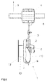
- ein erfindungsgemäßes Säschare in perspektivischer Darstellung,
- Fig. 2
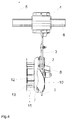
- das Säschar in der Ansicht von vorn,
- Fig. 3
- ein weiteres Säschar in perspektivischer Darstellung und
- Fig. 4
- das Säschar gemäß
Fig. 3 in der Ansicht von vorn. - Das Säschar 1 gemäß den
Fig. 1 und2 ist an einem Scharbalken eines nicht dargestellten Rahmens einer Sämaschine angeordnet. Derartige Säschare 1 sind bei einer Sämaschine in mehreren Querreihen im Abstand hintereinander und seitlich beabstandet und versetzt zueinander angeordnet. Eine derartige Sämaschine ist u. a. für die Mulchsaat bzw. Direktsaat vorgesehen. Die Säschare 1 weisen einen Scharstiel 2 auf, der über einen Scharhalter 3 mittels einer Lagereinrichtung 4 an sich quer zur Fahrtrichtung 5 erstreckenden Scharbalken 6 des Rahmens der Sämaschine in aufrechter Ebene bewegbar angeordnet sind. Hinter den Säscharen 1 ist jeweils ein als Tiefenführungsrolle 7 ausgebildetes Tiefenführungselement in einstellbarer Weise über einen Haltearm 8 an dem Scharhalter 3 in einstellbarer Weise befestigt. - Der Scharstiel 2 weist an seinem unteren Ende ein nach unten ragendes Aufreißelement 9 auf. Dem Scharstiel 2 ist oberhalb des Aufreißelementes 9 ein als Leitvorrichtung 10 ausgebildetes in sich verdrehtes Leitflächenelement zugeordnet. Dieses Leitflächenelement 10 ist an dem Scharstiel 2 und an dem Aufreißelement 9 befestigt. Das Leitflächenelement 10 ist schräg zur Fahrtrichtung 5 verlaufend angeordnet und nur einseitig schräg verlaufend ausgerichtet ausgebildet. Die Leitvorrichtung 10 ist als pflugähnliches und in sich verdrehtes Leitflächenelement ausgebildet.
- Die Tiefenführungsrolle 7 ist über ihre Felge 11 mittels eines Drehlagers drehbar an dem Haltearm 8 gelagert. An der Felge 11 der Tiefenführungsrolle 7 ist mittels einer zylinderförmigen Halterung 12 die kreisförmig ausgebildete Erdfangscheibe 13 angeordnet. Über die Tiefenführungsrolle 7 wird das Säschar 1 in der Tiefe geführt. Über die zylinderförmige Haltevorrichtung 12 ist die Erdfangscheibe 13 beabstandet zu der Tiefenführungsrolle 7 an der Tiefenführungsrolle 7 befestigt. Die Erdfangscheibe 13 überragt nicht den Außenumfang der Tiefenführungsrolle 7. Die zylinderförmige Halterung 12 weist einen wesentlich kleineren Durchmesser als die Tiefenführungsrolle 7 und die Erdfangscheibe 13 auf. Hierbei ist der Durchmesser der zylinderförmigen Halterung 12 kleiner als der halbe Durchmesser der Erdfangscheibe 13 oder der Tiefenführungsrolle 7. Die Erdfangscheibe 13 ist derart an der Tiefenführungsrolle 7 angeordnet, dass sie zumindest annähernd die gesamte von den Leitflächenelemente 10 umgeleitete Erde zur Begrenzung der Wurfweite der von der Leitvorrichtung 10 umgeleiteten Erde auffängt.
- Die Funktionsweise der Erdfangscheibe 13 in Verbindung mit der Leitvorrichtung 10 ist folgende:
- Durch das Aufreißelement 9 wird der Boden zur Schaffung einer Säfurche aufgerissen. Durch das in sich verdrehte Leitelement 10 wird die Erde zur Schaffung einer Säfurche zur Seite geleitet. Die hinter dem Leitelement 10 und dem Aufreißelement 9 an der Tiefenführungsrolle 7 angeordnete Erdfangscheibe 13 fängt die von der Leitvorrichtung 10 zur Seite geleitete Erde auf und führt sie in die Säfurche zur Bedeckung des durch die Saatzuführleitung 14 geförderte und in der Säfurche abgelegte Saatgut zurück. Die Erdfangscheibe 13 dreht sich mit der Andruckrolle 7. Die Erdfangscheibe 13 kann aus einem flexiblen Material hergestellt sein.
- Das Säschar gemäß
Fig. 3 und4 unterscheidet sich von dem Säschar gemäß derFig. 1 und2 dadurch, dass auf der Außenseite der zylinderförmigen Halterung 12 Erdabweiselemente 15 angeordnet sind. Mittels dieser Erdabweiselemente 15 wird eine verbesserte Zurückleitung der von der Erdfangscheibe 13 aufgefangenen Erde zurück in die Säfurche erzielt.
Claims (8)
- Sämaschine zum Ausbringen von Saatgut und/oder Düngemitteln mit einem Rahmen, Vorratsbehälter, Säscharen und Leitvorrichtungen zum gezielten Ablegen des von den zumindest einem Scharstiel aufweisenden Säscharen beim Schaffen der Säfurchen aus der Säfurche geworfenen Bodenmaterials, wobei die Leitvorrichtung als pflugähnliches in sich verdrehtes Leitflächenelement ausgebildet ist, wobei das Leitflächenelement an dem zumindest an einem Scharstiel befestigten Säschar befestigt ist, wobei die Leitvorrichtung schräg zur Fahrtrichtung verlaufend angeordnet und nur einseitig schräg ausgerichtet verlaufend ausgebildet ist, wobei hinter dem Säschar ein mit dem Säschar über eine Haltevorrichtung verbundene und das Säschar in der Tiefe führende Tiefenführungsrolle angeordnet ist, dadurch gekennzeichnet, dass über eine Haltevorrichtung (12) eine zumindest annähernd kreisförmigen Erdfangscheibe (13) beabstandet zu der Tiefenführungsrolle (13) an der Tiefenführungsrolle (7) befestigt ist, dass die Erdfangscheibe (13) den Außenumfang der Tiefenführungsrolle (7) nicht überragt.
- Sämaschine nach Anspruch 1, dadurch gekennzeichnet, dass die Erdfangscheibe (13) derart an der Tiefenführungsrolle (7) angeordnet ist, dass sie zumindest annähernd die gesamte von dem Leitflächenelement (10) umgeleitete Erde zur Begrenzung der Wurfweite der von der Leitvorrichtung (10) umgeleiteten Erde auffängt.
- Sämaschine nach zumindest einem der vorstehenden Ansprüche, dadurch gekennzeichnet, dass die die Erdfangscheibe (13) mit der Tiefenführungsrolle (7) verbindenden Halterung (10) zylinderförmig ausgebildet ist und einen wesentlich kleineren Durchmesser als die Tiefenführungsrolle (7) und die Erdfangscheibe (13) aufweist.
- Sämaschine nach zumindest einem der vorstehenden Ansprüche, dadurch gekennzeichnet, dass der Durchmesser der zylinderförmigen Halterung (10) kleiner als der halbe Durchmesser der Erdauffangscheibe (13) oder der Tiefenführungsrolle (7) ist.
- Sämaschine nach zumindest einem der vorstehenden Ansprüche, dadurch gekennzeichnet, dass auf der Außenseite der zylinderförmigen Halterung (10) Erdabweißelemente (15) angeordnet sind.
- Sämaschine nach zumindest einem der vorstehenden Ansprüche, dadurch gekennzeichnet, dass die Erdfangscheibe (15) einen gleichen oder kleineren Durchmesser als die Tiefenführungsrolle (7) aufweist.
- Sämaschine nach zumindest einem der vorstehenden Ansprüche, dadurch gekennzeichnet, dass die Erdfangscheibe (13) einen gleichen oder größeren Durchmesser als die Tiefenführungsrolle (7) aufweist.
- Sämaschine nach zumindest einem der vorstehenden Ansprüche, dadurch gekennzeichnet, dass die Erdfangscheibe (13) aus einem flexiblen Material besteht.
Priority Applications (1)
| Application Number | Priority Date | Filing Date | Title |
|---|---|---|---|
| PL10401210T PL2335466T3 (pl) | 2009-12-10 | 2010-12-03 | Siewnik |
Applications Claiming Priority (1)
| Application Number | Priority Date | Filing Date | Title |
|---|---|---|---|
| DE102009044854A DE102009044854A1 (de) | 2009-12-10 | 2009-12-10 | Sämaschine |
Publications (2)
| Publication Number | Publication Date |
|---|---|
| EP2335466A1 true EP2335466A1 (de) | 2011-06-22 |
| EP2335466B1 EP2335466B1 (de) | 2013-04-17 |
Family
ID=43926886
Family Applications (1)
| Application Number | Title | Priority Date | Filing Date |
|---|---|---|---|
| EP10401210.9A Active EP2335466B1 (de) | 2009-12-10 | 2010-12-03 | Sämaschine |
Country Status (3)
| Country | Link |
|---|---|
| EP (1) | EP2335466B1 (de) |
| DE (1) | DE102009044854A1 (de) |
| PL (1) | PL2335466T3 (de) |
Cited By (1)
| Publication number | Priority date | Publication date | Assignee | Title |
|---|---|---|---|---|
| EP3782443A3 (de) * | 2019-08-23 | 2021-05-26 | Horsch Maschinen GmbH | Landwirtschaftliche bodenbearbeitungsmaschine zur bearbeitung von reihenkulturen |
Citations (5)
| Publication number | Priority date | Publication date | Assignee | Title |
|---|---|---|---|---|
| DE2018178A1 (de) | 1969-04-22 | 1970-11-12 | Martin, Albert; Heritier, Jean-Jer6moe; Chamoson (Schweiz) | Pflug |
| DE102005042459A1 (de) | 2005-09-06 | 2007-03-08 | Amazonen-Werke H. Dreyer Gmbh & Co. Kg | Sämaschine |
| DE102008008553A1 (de) * | 2008-02-12 | 2009-08-13 | Amazonen-Werke H. Dreyer Gmbh & Co. Kg | Sämaschine |
| WO2009100833A1 (de) | 2008-02-12 | 2009-08-20 | Amazonen-Werke H. Dreyer Gmbh & Co. Kg | Sämaschine |
| EP2208409A1 (de) * | 2009-01-15 | 2010-07-21 | Fritz Güttler | Säschar-Modul für die Direktsaat und Direktsaat-Maschinenkombination |
-
2009
- 2009-12-10 DE DE102009044854A patent/DE102009044854A1/de not_active Withdrawn
-
2010
- 2010-12-03 PL PL10401210T patent/PL2335466T3/pl unknown
- 2010-12-03 EP EP10401210.9A patent/EP2335466B1/de active Active
Patent Citations (5)
| Publication number | Priority date | Publication date | Assignee | Title |
|---|---|---|---|---|
| DE2018178A1 (de) | 1969-04-22 | 1970-11-12 | Martin, Albert; Heritier, Jean-Jer6moe; Chamoson (Schweiz) | Pflug |
| DE102005042459A1 (de) | 2005-09-06 | 2007-03-08 | Amazonen-Werke H. Dreyer Gmbh & Co. Kg | Sämaschine |
| DE102008008553A1 (de) * | 2008-02-12 | 2009-08-13 | Amazonen-Werke H. Dreyer Gmbh & Co. Kg | Sämaschine |
| WO2009100833A1 (de) | 2008-02-12 | 2009-08-20 | Amazonen-Werke H. Dreyer Gmbh & Co. Kg | Sämaschine |
| EP2208409A1 (de) * | 2009-01-15 | 2010-07-21 | Fritz Güttler | Säschar-Modul für die Direktsaat und Direktsaat-Maschinenkombination |
Cited By (1)
| Publication number | Priority date | Publication date | Assignee | Title |
|---|---|---|---|---|
| EP3782443A3 (de) * | 2019-08-23 | 2021-05-26 | Horsch Maschinen GmbH | Landwirtschaftliche bodenbearbeitungsmaschine zur bearbeitung von reihenkulturen |
Also Published As
| Publication number | Publication date |
|---|---|
| DE102009044854A1 (de) | 2011-06-16 |
| PL2335466T3 (pl) | 2013-09-30 |
| EP2335466B1 (de) | 2013-04-17 |
Similar Documents
| Publication | Publication Date | Title |
|---|---|---|
| EP3065529B1 (de) | Sämaschine | |
| EP2301315B1 (de) | Säschareinheit | |
| DE102007005801A1 (de) | Grubber | |
| EP1974596B1 (de) | Säscharanordnung | |
| EP0102557A2 (de) | Sämaschine | |
| DE102015111779A1 (de) | Sämaschine | |
| DE102011054184A1 (de) | Sämaschine | |
| DE102008008553A1 (de) | Sämaschine | |
| EP2335466B1 (de) | Sämaschine | |
| WO2008017403A1 (de) | Sämaschine | |
| EP2240007B1 (de) | Sämaschine | |
| DE102010000527A1 (de) | Sämaschine | |
| DE102013112229A1 (de) | Sämaschine | |
| DE102016112460A1 (de) | Landwirtschaftliche Sämaschine mit Zustreich- und/oder Andrückvorrichtung | |
| CA2927388C (en) | Replaceable wear insert for furrow opening assembly | |
| DE102007011752A1 (de) | Sämaschine | |
| DE4138633C2 (de) | Ausräumaggregat für Sämaschinen | |
| DE102012105561B4 (de) | Strohräumer für Drillmaschinen | |
| EP2954768A1 (de) | Sämaschineneinheit und sämaschine | |
| WO2008061621A1 (de) | Sämaschine | |
| DE2540247A1 (de) | Bestellgeraet fuer die landwirtschaft | |
| DE102011056857A1 (de) | Sämaschine | |
| WO2004078053A2 (de) | Sämaschine | |
| EP3320764B1 (de) | Säreihe für eine sämaschine | |
| AT218775B (de) | Pflanzensetzmaschine |
Legal Events
| Date | Code | Title | Description |
|---|---|---|---|
| PUAI | Public reference made under article 153(3) epc to a published international application that has entered the european phase |
Free format text: ORIGINAL CODE: 0009012 |
|
| AK | Designated contracting states |
Kind code of ref document: A1 Designated state(s): AL AT BE BG CH CY CZ DE DK EE ES FI FR GB GR HR HU IE IS IT LI LT LU LV MC MK MT NL NO PL PT RO RS SE SI SK SM TR |
|
| AX | Request for extension of the european patent |
Extension state: BA ME |
|
| 17P | Request for examination filed |
Effective date: 20111213 |
|
| RIC1 | Information provided on ipc code assigned before grant |
Ipc: A01C 5/06 20060101AFI20121113BHEP |
|
| GRAP | Despatch of communication of intention to grant a patent |
Free format text: ORIGINAL CODE: EPIDOSNIGR1 |
|
| GRAS | Grant fee paid |
Free format text: ORIGINAL CODE: EPIDOSNIGR3 |
|
| GRAA | (expected) grant |
Free format text: ORIGINAL CODE: 0009210 |
|
| AK | Designated contracting states |
Kind code of ref document: B1 Designated state(s): AL AT BE BG CH CY CZ DE DK EE ES FI FR GB GR HR HU IE IS IT LI LT LU LV MC MK MT NL NO PL PT RO RS SE SI SK SM TR |
|
| REG | Reference to a national code |
Ref country code: GB Ref legal event code: FG4D Free format text: NOT ENGLISH |
|
| REG | Reference to a national code |
Ref country code: CH Ref legal event code: EP |
|
| REG | Reference to a national code |
Ref country code: IE Ref legal event code: FG4D Free format text: LANGUAGE OF EP DOCUMENT: GERMAN |
|
| REG | Reference to a national code |
Ref country code: AT Ref legal event code: REF Ref document number: 606630 Country of ref document: AT Kind code of ref document: T Effective date: 20130515 |
|
| REG | Reference to a national code |
Ref country code: DE Ref legal event code: R096 Ref document number: 502010002961 Country of ref document: DE Effective date: 20130613 |
|
| REG | Reference to a national code |
Ref country code: SE Ref legal event code: TRGR |
|
| REG | Reference to a national code |
Ref country code: LT Ref legal event code: MG4D |
|
| REG | Reference to a national code |
Ref country code: PL Ref legal event code: T3 |
|
| REG | Reference to a national code |
Ref country code: NL Ref legal event code: VDEP Effective date: 20130417 |
|
| PG25 | Lapsed in a contracting state [announced via postgrant information from national office to epo] |
Ref country code: ES Free format text: LAPSE BECAUSE OF FAILURE TO SUBMIT A TRANSLATION OF THE DESCRIPTION OR TO PAY THE FEE WITHIN THE PRESCRIBED TIME-LIMIT Effective date: 20130728 Ref country code: PT Free format text: LAPSE BECAUSE OF FAILURE TO SUBMIT A TRANSLATION OF THE DESCRIPTION OR TO PAY THE FEE WITHIN THE PRESCRIBED TIME-LIMIT Effective date: 20130819 Ref country code: NO Free format text: LAPSE BECAUSE OF FAILURE TO SUBMIT A TRANSLATION OF THE DESCRIPTION OR TO PAY THE FEE WITHIN THE PRESCRIBED TIME-LIMIT Effective date: 20130717 Ref country code: IS Free format text: LAPSE BECAUSE OF FAILURE TO SUBMIT A TRANSLATION OF THE DESCRIPTION OR TO PAY THE FEE WITHIN THE PRESCRIBED TIME-LIMIT Effective date: 20130817 Ref country code: GR Free format text: LAPSE BECAUSE OF FAILURE TO SUBMIT A TRANSLATION OF THE DESCRIPTION OR TO PAY THE FEE WITHIN THE PRESCRIBED TIME-LIMIT Effective date: 20130718 Ref country code: FI Free format text: LAPSE BECAUSE OF FAILURE TO SUBMIT A TRANSLATION OF THE DESCRIPTION OR TO PAY THE FEE WITHIN THE PRESCRIBED TIME-LIMIT Effective date: 20130417 Ref country code: LT Free format text: LAPSE BECAUSE OF FAILURE TO SUBMIT A TRANSLATION OF THE DESCRIPTION OR TO PAY THE FEE WITHIN THE PRESCRIBED TIME-LIMIT Effective date: 20130417 Ref country code: SI Free format text: LAPSE BECAUSE OF FAILURE TO SUBMIT A TRANSLATION OF THE DESCRIPTION OR TO PAY THE FEE WITHIN THE PRESCRIBED TIME-LIMIT Effective date: 20130417 |
|
| PG25 | Lapsed in a contracting state [announced via postgrant information from national office to epo] |
Ref country code: BG Free format text: LAPSE BECAUSE OF FAILURE TO SUBMIT A TRANSLATION OF THE DESCRIPTION OR TO PAY THE FEE WITHIN THE PRESCRIBED TIME-LIMIT Effective date: 20130717 Ref country code: RS Free format text: LAPSE BECAUSE OF FAILURE TO SUBMIT A TRANSLATION OF THE DESCRIPTION OR TO PAY THE FEE WITHIN THE PRESCRIBED TIME-LIMIT Effective date: 20130417 Ref country code: LV Free format text: LAPSE BECAUSE OF FAILURE TO SUBMIT A TRANSLATION OF THE DESCRIPTION OR TO PAY THE FEE WITHIN THE PRESCRIBED TIME-LIMIT Effective date: 20130417 Ref country code: HR Free format text: LAPSE BECAUSE OF FAILURE TO SUBMIT A TRANSLATION OF THE DESCRIPTION OR TO PAY THE FEE WITHIN THE PRESCRIBED TIME-LIMIT Effective date: 20130417 Ref country code: CY Free format text: LAPSE BECAUSE OF FAILURE TO SUBMIT A TRANSLATION OF THE DESCRIPTION OR TO PAY THE FEE WITHIN THE PRESCRIBED TIME-LIMIT Effective date: 20130417 |
|
| PG25 | Lapsed in a contracting state [announced via postgrant information from national office to epo] |
Ref country code: SK Free format text: LAPSE BECAUSE OF FAILURE TO SUBMIT A TRANSLATION OF THE DESCRIPTION OR TO PAY THE FEE WITHIN THE PRESCRIBED TIME-LIMIT Effective date: 20130417 Ref country code: DK Free format text: LAPSE BECAUSE OF FAILURE TO SUBMIT A TRANSLATION OF THE DESCRIPTION OR TO PAY THE FEE WITHIN THE PRESCRIBED TIME-LIMIT Effective date: 20130417 Ref country code: EE Free format text: LAPSE BECAUSE OF FAILURE TO SUBMIT A TRANSLATION OF THE DESCRIPTION OR TO PAY THE FEE WITHIN THE PRESCRIBED TIME-LIMIT Effective date: 20130417 Ref country code: CZ Free format text: LAPSE BECAUSE OF FAILURE TO SUBMIT A TRANSLATION OF THE DESCRIPTION OR TO PAY THE FEE WITHIN THE PRESCRIBED TIME-LIMIT Effective date: 20130417 |
|
| PLBE | No opposition filed within time limit |
Free format text: ORIGINAL CODE: 0009261 |
|
| STAA | Information on the status of an ep patent application or granted ep patent |
Free format text: STATUS: NO OPPOSITION FILED WITHIN TIME LIMIT |
|
| PG25 | Lapsed in a contracting state [announced via postgrant information from national office to epo] |
Ref country code: NL Free format text: LAPSE BECAUSE OF FAILURE TO SUBMIT A TRANSLATION OF THE DESCRIPTION OR TO PAY THE FEE WITHIN THE PRESCRIBED TIME-LIMIT Effective date: 20130417 Ref country code: RO Free format text: LAPSE BECAUSE OF FAILURE TO SUBMIT A TRANSLATION OF THE DESCRIPTION OR TO PAY THE FEE WITHIN THE PRESCRIBED TIME-LIMIT Effective date: 20130417 |
|
| 26N | No opposition filed |
Effective date: 20140120 |
|
| REG | Reference to a national code |
Ref country code: DE Ref legal event code: R097 Ref document number: 502010002961 Country of ref document: DE Effective date: 20140120 |
|
| BERE | Be: lapsed |
Owner name: AMAZONEN-WERKE H. DREYER G.M.B.H. & CO. KG Effective date: 20131231 |
|
| PG25 | Lapsed in a contracting state [announced via postgrant information from national office to epo] |
Ref country code: LU Free format text: LAPSE BECAUSE OF FAILURE TO SUBMIT A TRANSLATION OF THE DESCRIPTION OR TO PAY THE FEE WITHIN THE PRESCRIBED TIME-LIMIT Effective date: 20131203 Ref country code: MC Free format text: LAPSE BECAUSE OF FAILURE TO SUBMIT A TRANSLATION OF THE DESCRIPTION OR TO PAY THE FEE WITHIN THE PRESCRIBED TIME-LIMIT Effective date: 20130417 |
|
| REG | Reference to a national code |
Ref country code: IE Ref legal event code: MM4A |
|
| PG25 | Lapsed in a contracting state [announced via postgrant information from national office to epo] |
Ref country code: IE Free format text: LAPSE BECAUSE OF NON-PAYMENT OF DUE FEES Effective date: 20131203 Ref country code: BE Free format text: LAPSE BECAUSE OF NON-PAYMENT OF DUE FEES Effective date: 20131231 |
|
| PG25 | Lapsed in a contracting state [announced via postgrant information from national office to epo] |
Ref country code: SM Free format text: LAPSE BECAUSE OF FAILURE TO SUBMIT A TRANSLATION OF THE DESCRIPTION OR TO PAY THE FEE WITHIN THE PRESCRIBED TIME-LIMIT Effective date: 20130417 |
|
| PG25 | Lapsed in a contracting state [announced via postgrant information from national office to epo] |
Ref country code: TR Free format text: LAPSE BECAUSE OF FAILURE TO SUBMIT A TRANSLATION OF THE DESCRIPTION OR TO PAY THE FEE WITHIN THE PRESCRIBED TIME-LIMIT Effective date: 20130417 |
|
| PG25 | Lapsed in a contracting state [announced via postgrant information from national office to epo] |
Ref country code: HU Free format text: LAPSE BECAUSE OF FAILURE TO SUBMIT A TRANSLATION OF THE DESCRIPTION OR TO PAY THE FEE WITHIN THE PRESCRIBED TIME-LIMIT; INVALID AB INITIO Effective date: 20101203 Ref country code: MK Free format text: LAPSE BECAUSE OF FAILURE TO SUBMIT A TRANSLATION OF THE DESCRIPTION OR TO PAY THE FEE WITHIN THE PRESCRIBED TIME-LIMIT Effective date: 20130417 |
|
| REG | Reference to a national code |
Ref country code: CH Ref legal event code: PL |
|
| GBPC | Gb: european patent ceased through non-payment of renewal fee |
Effective date: 20141203 |
|
| PG25 | Lapsed in a contracting state [announced via postgrant information from national office to epo] |
Ref country code: MT Free format text: LAPSE BECAUSE OF FAILURE TO SUBMIT A TRANSLATION OF THE DESCRIPTION OR TO PAY THE FEE WITHIN THE PRESCRIBED TIME-LIMIT Effective date: 20130417 |
|
| PG25 | Lapsed in a contracting state [announced via postgrant information from national office to epo] |
Ref country code: LI Free format text: LAPSE BECAUSE OF NON-PAYMENT OF DUE FEES Effective date: 20141231 Ref country code: CH Free format text: LAPSE BECAUSE OF NON-PAYMENT OF DUE FEES Effective date: 20141231 Ref country code: GB Free format text: LAPSE BECAUSE OF NON-PAYMENT OF DUE FEES Effective date: 20141203 |
|
| REG | Reference to a national code |
Ref country code: FR Ref legal event code: PLFP Year of fee payment: 6 |
|
| REG | Reference to a national code |
Ref country code: FR Ref legal event code: PLFP Year of fee payment: 7 |
|
| REG | Reference to a national code |
Ref country code: FR Ref legal event code: PLFP Year of fee payment: 8 |
|
| REG | Reference to a national code |
Ref country code: FR Ref legal event code: PLFP Year of fee payment: 9 |
|
| PG25 | Lapsed in a contracting state [announced via postgrant information from national office to epo] |
Ref country code: AL Free format text: LAPSE BECAUSE OF FAILURE TO SUBMIT A TRANSLATION OF THE DESCRIPTION OR TO PAY THE FEE WITHIN THE PRESCRIBED TIME-LIMIT Effective date: 20130417 |
|
| PGFP | Annual fee paid to national office [announced via postgrant information from national office to epo] |
Ref country code: AT Payment date: 20201125 Year of fee payment: 11 |
|
| REG | Reference to a national code |
Ref country code: DE Ref legal event code: R082 Ref document number: 502010002961 Country of ref document: DE Representative=s name: KILBURN & STRODE LLP, GB Ref country code: DE Ref legal event code: R082 Ref document number: 502010002961 Country of ref document: DE Representative=s name: KILBURN & STRODE LLP, NL Ref country code: DE Ref legal event code: R081 Ref document number: 502010002961 Country of ref document: DE Owner name: AMAZONEN-WERKE H. DREYER SE & CO. KG, DE Free format text: FORMER OWNER: AMAZONEN-WERKE H. DREYER GMBH & CO. KG, 49205 HASBERGEN, DE |
|
| REG | Reference to a national code |
Ref country code: DE Ref legal event code: R082 Ref document number: 502010002961 Country of ref document: DE Representative=s name: KILBURN & STRODE LLP, NL |
|
| REG | Reference to a national code |
Ref country code: AT Ref legal event code: MM01 Ref document number: 606630 Country of ref document: AT Kind code of ref document: T Effective date: 20211203 |
|
| PG25 | Lapsed in a contracting state [announced via postgrant information from national office to epo] |
Ref country code: AT Free format text: LAPSE BECAUSE OF NON-PAYMENT OF DUE FEES Effective date: 20211203 |
|
| P01 | Opt-out of the competence of the unified patent court (upc) registered |
Effective date: 20230523 |
|
| PGFP | Annual fee paid to national office [announced via postgrant information from national office to epo] |
Ref country code: PL Payment date: 20250912 Year of fee payment: 16 |
|
| PGFP | Annual fee paid to national office [announced via postgrant information from national office to epo] |
Ref country code: FR Payment date: 20250930 Year of fee payment: 16 |
|
| PGFP | Annual fee paid to national office [announced via postgrant information from national office to epo] |
Ref country code: DE Payment date: 20250930 Year of fee payment: 16 |
|
| PGFP | Annual fee paid to national office [announced via postgrant information from national office to epo] |
Ref country code: IT Payment date: 20251121 Year of fee payment: 16 |
|
| PGFP | Annual fee paid to national office [announced via postgrant information from national office to epo] |
Ref country code: SE Payment date: 20251001 Year of fee payment: 16 |