EP2333578A2 - Procédé et appareil de commande pour la détermination d'une direction de déplacement d'un objet se déplaçant vers un véhicule - Google Patents
Procédé et appareil de commande pour la détermination d'une direction de déplacement d'un objet se déplaçant vers un véhicule Download PDFInfo
- Publication number
- EP2333578A2 EP2333578A2 EP10193185A EP10193185A EP2333578A2 EP 2333578 A2 EP2333578 A2 EP 2333578A2 EP 10193185 A EP10193185 A EP 10193185A EP 10193185 A EP10193185 A EP 10193185A EP 2333578 A2 EP2333578 A2 EP 2333578A2
- Authority
- EP
- European Patent Office
- Prior art keywords
- vehicle
- sensor
- sensor signal
- information
- signal
- Prior art date
- Legal status (The legal status is an assumption and is not a legal conclusion. Google has not performed a legal analysis and makes no representation as to the accuracy of the status listed.)
- Granted
Links
Images


Classifications
-
- G—PHYSICS
- G01—MEASURING; TESTING
- G01S—RADIO DIRECTION-FINDING; RADIO NAVIGATION; DETERMINING DISTANCE OR VELOCITY BY USE OF RADIO WAVES; LOCATING OR PRESENCE-DETECTING BY USE OF THE REFLECTION OR RERADIATION OF RADIO WAVES; ANALOGOUS ARRANGEMENTS USING OTHER WAVES
- G01S13/00—Systems using the reflection or reradiation of radio waves, e.g. radar systems; Analogous systems using reflection or reradiation of waves whose nature or wavelength is irrelevant or unspecified
- G01S13/88—Radar or analogous systems specially adapted for specific applications
- G01S13/93—Radar or analogous systems specially adapted for specific applications for anti-collision purposes
- G01S13/931—Radar or analogous systems specially adapted for specific applications for anti-collision purposes of land vehicles
-
- B—PERFORMING OPERATIONS; TRANSPORTING
- B60—VEHICLES IN GENERAL
- B60R—VEHICLES, VEHICLE FITTINGS, OR VEHICLE PARTS, NOT OTHERWISE PROVIDED FOR
- B60R21/00—Arrangements or fittings on vehicles for protecting or preventing injuries to occupants or pedestrians in case of accidents or other traffic risks
- B60R21/01—Electrical circuits for triggering passive safety arrangements, e.g. airbags, safety belt tighteners, in case of vehicle accidents or impending vehicle accidents
- B60R21/013—Electrical circuits for triggering passive safety arrangements, e.g. airbags, safety belt tighteners, in case of vehicle accidents or impending vehicle accidents including means for detecting collisions, impending collisions or roll-over
- B60R21/0134—Electrical circuits for triggering passive safety arrangements, e.g. airbags, safety belt tighteners, in case of vehicle accidents or impending vehicle accidents including means for detecting collisions, impending collisions or roll-over responsive to imminent contact with an obstacle, e.g. using radar systems
-
- B—PERFORMING OPERATIONS; TRANSPORTING
- B60—VEHICLES IN GENERAL
- B60W—CONJOINT CONTROL OF VEHICLE SUB-UNITS OF DIFFERENT TYPE OR DIFFERENT FUNCTION; CONTROL SYSTEMS SPECIALLY ADAPTED FOR HYBRID VEHICLES; ROAD VEHICLE DRIVE CONTROL SYSTEMS FOR PURPOSES NOT RELATED TO THE CONTROL OF A PARTICULAR SUB-UNIT
- B60W30/00—Purposes of road vehicle drive control systems not related to the control of a particular sub-unit, e.g. of systems using conjoint control of vehicle sub-units, or advanced driver assistance systems for ensuring comfort, stability and safety or drive control systems for propelling or retarding the vehicle
- B60W30/08—Active safety systems predicting or avoiding probable or impending collision or attempting to minimise its consequences
- B60W30/095—Predicting travel path or likelihood of collision
- B60W30/0956—Predicting travel path or likelihood of collision the prediction being responsive to traffic or environmental parameters
-
- B—PERFORMING OPERATIONS; TRANSPORTING
- B60—VEHICLES IN GENERAL
- B60W—CONJOINT CONTROL OF VEHICLE SUB-UNITS OF DIFFERENT TYPE OR DIFFERENT FUNCTION; CONTROL SYSTEMS SPECIALLY ADAPTED FOR HYBRID VEHICLES; ROAD VEHICLE DRIVE CONTROL SYSTEMS FOR PURPOSES NOT RELATED TO THE CONTROL OF A PARTICULAR SUB-UNIT
- B60W50/00—Details of control systems for road vehicle drive control not related to the control of a particular sub-unit, e.g. process diagnostic or vehicle driver interfaces
- B60W50/0097—Predicting future conditions
-
- G—PHYSICS
- G01—MEASURING; TESTING
- G01S—RADIO DIRECTION-FINDING; RADIO NAVIGATION; DETERMINING DISTANCE OR VELOCITY BY USE OF RADIO WAVES; LOCATING OR PRESENCE-DETECTING BY USE OF THE REFLECTION OR RERADIATION OF RADIO WAVES; ANALOGOUS ARRANGEMENTS USING OTHER WAVES
- G01S13/00—Systems using the reflection or reradiation of radio waves, e.g. radar systems; Analogous systems using reflection or reradiation of waves whose nature or wavelength is irrelevant or unspecified
- G01S13/02—Systems using reflection of radio waves, e.g. primary radar systems; Analogous systems
- G01S13/50—Systems of measurement based on relative movement of target
- G01S13/58—Velocity or trajectory determination systems; Sense-of-movement determination systems
- G01S13/588—Velocity or trajectory determination systems; Sense-of-movement determination systems deriving the velocity value from the range measurement
-
- G—PHYSICS
- G01—MEASURING; TESTING
- G01S—RADIO DIRECTION-FINDING; RADIO NAVIGATION; DETERMINING DISTANCE OR VELOCITY BY USE OF RADIO WAVES; LOCATING OR PRESENCE-DETECTING BY USE OF THE REFLECTION OR RERADIATION OF RADIO WAVES; ANALOGOUS ARRANGEMENTS USING OTHER WAVES
- G01S13/00—Systems using the reflection or reradiation of radio waves, e.g. radar systems; Analogous systems using reflection or reradiation of waves whose nature or wavelength is irrelevant or unspecified
- G01S13/02—Systems using reflection of radio waves, e.g. primary radar systems; Analogous systems
- G01S13/50—Systems of measurement based on relative movement of target
- G01S13/58—Velocity or trajectory determination systems; Sense-of-movement determination systems
- G01S13/589—Velocity or trajectory determination systems; Sense-of-movement determination systems measuring the velocity vector
-
- G—PHYSICS
- G01—MEASURING; TESTING
- G01S—RADIO DIRECTION-FINDING; RADIO NAVIGATION; DETERMINING DISTANCE OR VELOCITY BY USE OF RADIO WAVES; LOCATING OR PRESENCE-DETECTING BY USE OF THE REFLECTION OR RERADIATION OF RADIO WAVES; ANALOGOUS ARRANGEMENTS USING OTHER WAVES
- G01S13/00—Systems using the reflection or reradiation of radio waves, e.g. radar systems; Analogous systems using reflection or reradiation of waves whose nature or wavelength is irrelevant or unspecified
- G01S13/87—Combinations of radar systems, e.g. primary radar and secondary radar
-
- G—PHYSICS
- G01—MEASURING; TESTING
- G01S—RADIO DIRECTION-FINDING; RADIO NAVIGATION; DETERMINING DISTANCE OR VELOCITY BY USE OF RADIO WAVES; LOCATING OR PRESENCE-DETECTING BY USE OF THE REFLECTION OR RERADIATION OF RADIO WAVES; ANALOGOUS ARRANGEMENTS USING OTHER WAVES
- G01S7/00—Details of systems according to groups G01S13/00, G01S15/00, G01S17/00
- G01S7/02—Details of systems according to groups G01S13/00, G01S15/00, G01S17/00 of systems according to group G01S13/00
- G01S7/41—Details of systems according to groups G01S13/00, G01S15/00, G01S17/00 of systems according to group G01S13/00 using analysis of echo signal for target characterisation; Target signature; Target cross-section
- G01S7/411—Identification of targets based on measurements of radar reflectivity
- G01S7/412—Identification of targets based on measurements of radar reflectivity based on a comparison between measured values and known or stored values
-
- G—PHYSICS
- G01—MEASURING; TESTING
- G01S—RADIO DIRECTION-FINDING; RADIO NAVIGATION; DETERMINING DISTANCE OR VELOCITY BY USE OF RADIO WAVES; LOCATING OR PRESENCE-DETECTING BY USE OF THE REFLECTION OR RERADIATION OF RADIO WAVES; ANALOGOUS ARRANGEMENTS USING OTHER WAVES
- G01S13/00—Systems using the reflection or reradiation of radio waves, e.g. radar systems; Analogous systems using reflection or reradiation of waves whose nature or wavelength is irrelevant or unspecified
- G01S13/02—Systems using reflection of radio waves, e.g. primary radar systems; Analogous systems
- G01S13/50—Systems of measurement based on relative movement of target
- G01S13/58—Velocity or trajectory determination systems; Sense-of-movement determination systems
- G01S13/62—Sense-of-movement determination
-
- G—PHYSICS
- G01—MEASURING; TESTING
- G01S—RADIO DIRECTION-FINDING; RADIO NAVIGATION; DETERMINING DISTANCE OR VELOCITY BY USE OF RADIO WAVES; LOCATING OR PRESENCE-DETECTING BY USE OF THE REFLECTION OR RERADIATION OF RADIO WAVES; ANALOGOUS ARRANGEMENTS USING OTHER WAVES
- G01S13/00—Systems using the reflection or reradiation of radio waves, e.g. radar systems; Analogous systems using reflection or reradiation of waves whose nature or wavelength is irrelevant or unspecified
- G01S13/88—Radar or analogous systems specially adapted for specific applications
- G01S13/93—Radar or analogous systems specially adapted for specific applications for anti-collision purposes
- G01S13/931—Radar or analogous systems specially adapted for specific applications for anti-collision purposes of land vehicles
- G01S2013/932—Radar or analogous systems specially adapted for specific applications for anti-collision purposes of land vehicles using own vehicle data, e.g. ground speed, steering wheel direction
-
- G—PHYSICS
- G01—MEASURING; TESTING
- G01S—RADIO DIRECTION-FINDING; RADIO NAVIGATION; DETERMINING DISTANCE OR VELOCITY BY USE OF RADIO WAVES; LOCATING OR PRESENCE-DETECTING BY USE OF THE REFLECTION OR RERADIATION OF RADIO WAVES; ANALOGOUS ARRANGEMENTS USING OTHER WAVES
- G01S13/00—Systems using the reflection or reradiation of radio waves, e.g. radar systems; Analogous systems using reflection or reradiation of waves whose nature or wavelength is irrelevant or unspecified
- G01S13/88—Radar or analogous systems specially adapted for specific applications
- G01S13/93—Radar or analogous systems specially adapted for specific applications for anti-collision purposes
- G01S13/931—Radar or analogous systems specially adapted for specific applications for anti-collision purposes of land vehicles
- G01S2013/9324—Alternative operation using ultrasonic waves
-
- G—PHYSICS
- G01—MEASURING; TESTING
- G01S—RADIO DIRECTION-FINDING; RADIO NAVIGATION; DETERMINING DISTANCE OR VELOCITY BY USE OF RADIO WAVES; LOCATING OR PRESENCE-DETECTING BY USE OF THE REFLECTION OR RERADIATION OF RADIO WAVES; ANALOGOUS ARRANGEMENTS USING OTHER WAVES
- G01S13/00—Systems using the reflection or reradiation of radio waves, e.g. radar systems; Analogous systems using reflection or reradiation of waves whose nature or wavelength is irrelevant or unspecified
- G01S13/88—Radar or analogous systems specially adapted for specific applications
- G01S13/93—Radar or analogous systems specially adapted for specific applications for anti-collision purposes
- G01S13/931—Radar or analogous systems specially adapted for specific applications for anti-collision purposes of land vehicles
- G01S2013/9327—Sensor installation details
- G01S2013/93271—Sensor installation details in the front of the vehicles
-
- G—PHYSICS
- G01—MEASURING; TESTING
- G01S—RADIO DIRECTION-FINDING; RADIO NAVIGATION; DETERMINING DISTANCE OR VELOCITY BY USE OF RADIO WAVES; LOCATING OR PRESENCE-DETECTING BY USE OF THE REFLECTION OR RERADIATION OF RADIO WAVES; ANALOGOUS ARRANGEMENTS USING OTHER WAVES
- G01S7/00—Details of systems according to groups G01S13/00, G01S15/00, G01S17/00
- G01S7/02—Details of systems according to groups G01S13/00, G01S15/00, G01S17/00 of systems according to group G01S13/00
- G01S7/41—Details of systems according to groups G01S13/00, G01S15/00, G01S17/00 of systems according to group G01S13/00 using analysis of echo signal for target characterisation; Target signature; Target cross-section
- G01S7/415—Identification of targets based on measurements of movement associated with the target
Definitions
- the present invention relates to a method for determining a direction of movement of an object to be moved onto a vehicle according to claim 1, a control device according to claim 9, a computer program product according to claim 10 and a sensor system according to claim 11.
- the DE 10 2006 036 934 A1 discloses an apparatus in which a vehicle sensor system is connected to a vehicle assembly to form a unit, wherein the vehicle sensor system and the vehicle assembly belong to different vehicle systems.
- the vehicle sensor system may be an accident sensor act.
- a reduction of the assembly work or assembly logistics can be achieved.
- the present invention proposes a method for impact protection, a control unit which uses this method, furthermore a corresponding computer program product, and finally a sensor system according to the independent patent claims.
- Advantageous embodiments emerge from the respective subclaims and the following description.
- the present invention further provides a control device which is designed to carry out or implement the steps of the method according to the invention. Also by this embodiment of the invention in the form of a control device, the object underlying the invention can be achieved quickly and efficiently.
- a control device can be understood to mean an electrical device which processes sensor signals and control signals in dependence thereon outputs.
- the control unit may have an interface, which may be formed in hardware and / or software.
- the interfaces can be part of a so-called system ASIC, for example, which contains various functions of the control unit.
- the interfaces are their own integrated circuits or at least partially consist of discrete components.
- the interfaces may be software modules that are present, for example, on a microcontroller in addition to other software modules.
- Also of advantage is a computer program product with program code which is stored on a machine-readable carrier such as a semiconductor memory, a hard disk memory or an optical memory and is used to carry out the method according to one of the embodiments described above, when the program is executed on a controller or a data processing unit becomes.
- a machine-readable carrier such as a semiconductor memory, a hard disk memory or an optical memory
- the present invention is based on the recognition that a precise movement path of this object towards the vehicle becomes possible by means of two signals, each representing a speed of an object approaching the vehicle, taken from different positions.
- two signals each representing a speed of an object approaching the vehicle, taken from different positions.
- to determine the path of movement in addition to the two signals even more information used by the distance of the two positions from each other, from which the speed of the approaching to the vehicle object is measured. This can be determined sufficiently accurately, for example, with the aid of measured distance gates and interpolated values in between.
- the speed and distance information can then be linked together by a triangulation method in such a way that the path of movement of the object to the vehicle is too precisely determinable.
- the present invention has the advantage that now technically simple and thus cost radar sensors can be installed at different positions (for example, in the front of the vehicle, but also on a vehicle side) and the information from the two sensors can be linked together in a computing unit in that an intelligent "anticipatory sensor" can now be formed from the two simple sensors.
- an intelligent "anticipatory sensor” can now be formed from the two simple sensors.
- the first sensor signal containing information about an intensity of a radar beam reflected from the object can be received and / or the second sensor signal containing information about a second sensor signal can be obtained in the step of receiving Intensity of a radar beam reflected from the object, and wherein in the step of linking further estimating an extension of the object to be moved on the vehicle using the information about the intensity of the first sensor signal and / or using the information on the intensity of the second sensor signal can be done.
- Such an embodiment of the present invention offers the advantage that in addition to a direction of movement of the object on the Vehicle is still an estimate of the size or width of the object is possible.
- the first and / or second sensor signal can only be further processed by software engineering and the additional information can be obtained from the amplitude of the corresponding sensor signal / the corresponding sensor signals.
- This information on the size of the object then allows an estimate of how hard an impact of the object would damage the vehicle and what safety means should be activated for the occupant protection and with what strength.
- the step of receiving the first sensor signal may be received, which contains information about the time course and the sensor signal change and / or wherein in the step of obtaining the second sensor signal can be, which information about the time course and the sensor signal change contains and wherein in the step of linking further estimation of a position (lateral orientation) of the moving object to the vehicle using the information from the time course of the signal change and / or using the information from the time course of the signal change can.
- a lateral orientation of the object can still be determined by the vehicle, so that not only the determination of the direction of movement but also a very precise position detection of the object with respect to the vehicle becomes possible. This improves an estimate of the impact time of the object on the vehicle and thus enables a more precise control of the corresponding safety means, which should compensate for or at least mitigate the consequences of the impact on the vehicle.
- a position of the object relative to the vehicle is determined on the basis of a difference quantity, a difference between a frequency or speed represented by the first sensor signal and a signal represented by the second sensor signal being used to determine the difference magnitude Frequency or speed is formed.
- a coarse position determination of the object with respect to the By very simple to implement algorithm functions Vehicle becomes possible.
- Such a technically very simple to implement the function is especially simplified in addition, especially when a sign of the difference size is evaluated.
- a position of the object can be detected centrally to the vehicle when the difference size is within a tolerance range by a value of zero.
- a position of the object in the traveling direction in the step of linking, can be recognized on the right side of the vehicle when the difference amount has a positive value.
- a position of the object in the direction of travel seen left side can be detected in the step of linking, if the difference size has a negative value. Or vice versa, depending on the subtraction formula.
- similar findings can also be achieved by means of a division.
- the method may further comprise a step of receiving a third sensor signal representing an acceleration of at least one component of the vehicle greater than an acceleration threshold, the method further comprising a step of activating a vehicle occupant protection means, as appropriate after a certain direction of movement of the object in the direction of the vehicle, the third sensor signal is received.
- the first sensor signal for example, as a radar signal
- the third sensor signal represents an acceleration in the impact of the object on the vehicle, which is determined by an acceleration sensor , which is installed together with the corresponding radar sensor in an integrated sensor.
- the third sensor signal can also be generated from a plurality of other acceleration-based sensor signals.
- FIG. 1 shows a block diagram of a first embodiment of the present invention, in which a system structure with two sensors and a central controller are used. It is in the left display off Fig. 1 a vehicle 100 reproduced, in which in the region of the left front side, a first sensor 110 and in the region of the right front side, a second sensor 120 are arranged. Both the first sensor 110 and the second sensor 120 are connected to a central evaluation unit 130 which is, for example, an airbag control unit.
- a central evaluation unit 130 which is, for example, an airbag control unit.
- the first sensor 110 monitors a first detection area 140, for example by emitting a radar beam into this first monitoring area 140 and receiving a reflection of this radar beam at an object in the first detection area 140.
- a first detection area 140 for example by emitting a radar beam into this first monitoring area 140 and receiving a reflection of this radar beam at an object in the first detection area 140.
- an evaluation of the Doppler frequency shift between the emitted radar beam and the received radar beam is performed, so that a speed component of the object is detected on the vehicle 100 / the sensor 110.
- an acceleration sensor may also be contained in the first sensor 110, which measures an acceleration behavior of components in the region of the left front side of the vehicle 100 during the crash, and also forwards a corresponding acceleration signal to the central evaluation unit 130.
- the second sensor 120 is constructed identically to the first sensor 110, for example, so that a second detection area 150 is monitored by the second sensor 120. Since the second sensor 120 is installed on the right side in the front area of the vehicle 100, an object approaching the vehicle 100 is likely to enter an overlap area that is both part of the first detection area 140 and part of the second Detection area 150 is. In this case, the approach of the object to the vehicle 100 is detected by both the first sensor 110 and the second sensor 120, but from different angles of view. A more detailed description of the evaluation of the signals from the first sensor 110 and the second sensor 120 (for example, in the central evaluation unit 130) will be explained in more detail below.
- certain occupant protection means can already be activated or placed in an elevated alarm state prior to an impact of the object on the vehicle 100.
- a trigger threshold for an occupant airbag 160 may be lowered, or the information about the incoming object may be used as a plausibility signal for triggering this occupant airbag 160.
- a belt tensioner 170 can be activated in order to hold or bring a vehicle occupant into an optimum position for the protective effect of an airbag before an impact of the object on the vehicle.
- acceleration sensors are also installed in the first sensor 110 and / or the second sensor 120
- signals from these acceleration sensors can be used in a collision of the object with the vehicle 100 in the central evaluation unit 130 in order, together with the previously supplied signals, to (partially) sensors of the first sensor 110 or the second sensor 120 to cause both a triggering and a plausibility of the triggering of an occupant protection means in the vehicle.
- sensors for different physical sizes for example, in a common housing
- a low-cost radar sensor alone so a sensor that has a short range (usually less than 5 m) and neither directly different from each other in the detection range of each other, nor can determine the exact position (at most distance ranges are fixed), the required information to determine the direction of movement of the object usually not alone deliver directly. This necessary information should now, without the sensor is expensive again, be generated in the post-processing software.
- An important part of the invention is therefore to be seen in enabling a realization of a cheap (for example radar) sensor, which derives the necessary information, such as object extent, orientation, etc. from the radar reflections on the software side.
- a cheap (for example radar) sensor which derives the necessary information, such as object extent, orientation, etc. from the radar reflections on the software side.
- a sensor offers, as it is on the one hand very cheap, on the other hand, the short range is completely sufficient.
- control unit it makes sense to carry out an integration of the evaluation unit for the two sensors in the airbag control unit, since sufficient numerical power can be provided at low cost.
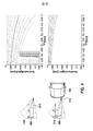
- the sensors 110 and 120 may each measure the exact velocity (here radial velocity 200 determined from the Doppler shift of the reflected radar beam compared to the radar beam emitted) of the colliding object 210, as shown in the right hand illustration Fig. 2 for the recognition of a punctual object is clarified.
- the left illustrations Fig. 2 For example, characteristics of the reflection intensity 220 are plotted against the radial velocity 230, the upper right representation representing measured values of the first sensor 110 and the lower right representation of FIG Fig. 2 represents the measured values of the second sensor 120. If a small point object 210 is centered on the vehicle 100, the two sensors will receive similar signals as shown in the right hand illustrations of FIGS Fig. 2 is reproduced.
- an extension of the object 210 can also be estimated via the reflection intensity 220.
- a difference quantity can be determined, which is determined from the determined radial frequencies of the first and second sensors 110 and 120.
- Fig. 3 is one too Fig. 2 reproduced analogous representation in which now the radial velocity of an extended object 210 to the Vehicle is determined to, from the lower right representation of the Fig. 3 a broader scattering of the radar beams reflected at the object 210 can be seen, from which consequently a broader dispersion of the different radial velocities 230 can be determined.
- the difference surface from the signal from the left sensor 110 and the signal from the right sensor 120 ie, in particular a signal from the first sensor 110-a signal from the second sensor 120
- it will be an extended object 210 that is to the right of the vehicle or at least on the right side of the vehicle 100.
- the difference surface of the signal of the left sensor 110 and the signal of the right sensor 120 ie in particular a signal of the first sensor 110 -a signal of the second sensor 120
- the total area is less than 0, then it is an offset of a punctual object 210.
- the offset of the object in relation to the vehicle can then be determined more accurately, for example, and also the orientation / angle to the ego vehicle can be derived.
- the offset results from the speed change.
- the radar sensor calculates the radial velocity of the object 210. By triangulating this information with analog information from the second sensor 120, the impact velocity can then be measured.
- the lateral offset 400 of the object can then be derived by means of trigonometry (for example, via sine / cosine calculations) or by previously determined comparison profiles.
- Such a determination of the offset is in the Fig. 4 shown, wherein in the upper two representations, a lateral offset of a point-shaped object 210 to a viewing direction 410 of the sensor in the direction of travel (left upper illustration of Figure 4 ) and an associated velocity profile of the radial velocity as a function of the offset (upper right representation of FIG Fig.
- an associated speed profile is shown, shown at a relative speed of 10 m / s between vehicle 100 and object 210 at a distance of 5 m between vehicle 100 and object 210 and an offset of 30 cm, wherein the object 210 has an extension of 40 cm (from the point of view of a sensor 110).
- the real speed curve will definitely be within the gray area.
- the boundary lines respectively correspond to the signal of a punctual object with an offset of 10 cm or 50 cm.
- Fig. 5 the determination of an impact angle of an object 210 on the vehicle 100 is shown schematically in more detail.
- the velocity profile for the incoming object 210 is shown, as shown by the first sensor 110 (left upper diagram Fig. 5 ) and the second sensor 120 (right upper diagram Fig. 5 ) are measured. It is in the two diagrams of the Fig. 5 the measured speed is plotted over a measuring time. From the two diagrams of Fig. 5 It can be clearly understood that the object 210 comes from a left side of the vehicle 100 and moves toward a right side of the vehicle 100.
- this radar sensor can also be replaced by another forward-looking sensor, such as an ultrasonic sensor.
- the detection of the speed of the incoming object 210 may be analogous when using an ultrasonic sensor; For example, it is also possible to evaluate a Doppler frequency shift of the ultrasound signal in order to be able to detect the speed of the incoming object in relation to the vehicle speed.
- the present invention also provides a method of impact protection in a collision of a vehicle with an object using data from at least one integrated sensor unit comprising at least one prospective sensor, in particular a radar sensor, and at least one acceleration sensor, the method comprising the steps of: receiving pre-data relating to the object via a pre-data interface from the look-ahead sensor, the pre-data representing at least one speed and / or distance of the object relative to the vehicle prior to the collision; Obtaining acceleration data via an acceleration data interface, wherein the acceleration data represents at least one acceleration of the vehicle after collision with the object; Combining the advance data with the acceleration data to form combination data, wherein the combination data particularly represents a collision velocity, a motion trajectory, and / or a distance of the object relative to the vehicle; and using the combination data in at least one impact protection device.
- the impact protection may be a protection against the consequences of the collision between the vehicle and the object, wherein the protection may extend to one or more occupants of the vehicle and / or the object.
- the object may be e.g. to act a pedestrian or cyclist.
- the integrated sensor unit may be a combination of two or more sensors.
- the combination may include a sensor that provides information that provides a period of time before the collision. This can e.g. be a radar sensor. Instead of the radar sensor, another sensor type can be used, which is designed to provide predictive data.
- the combination may include a sensor providing collision related information, e.g. about the impact severity, delivers. This can e.g. be an acceleration sensor.
- the acceleration sensor instead of the acceleration sensor, another sensor with which an impact severity can be detected, e.g. a pressure sensor, are used. Also combinations, e.g. from several radar sensors and / or acceleration sensors are possible.
- the sensor unit may also comprise a plurality of combinations of sensors spaced apart from each other, e.g. in a right or left side of a bumper of the vehicle, can be installed.
- the data may be, on the one hand, the advance data of the forward-looking sensor and, on the other hand, the acceleration data of the acceleration sensor, which are received via the corresponding interfaces, each sensor being equipped with its own interface.
- the combination data may include information describing both a pre-crash situation and the impact situation itself.
- the data may be information composed of the signals from the radar sensor and the acceleration sensor and output to various occupant protection systems prior to or at impact to provide impact protection.
- a further aspect of the invention is thus an implementation of a combined predictive crash sensor (PreCrash sensor) which, in addition to the acceleration data in the event of an impact, sends information about collision speed, trajectory and distance already before the impact.
- the predictive crash sensor may be considered as a combination of an acceleration sensor be realized with a one-chip radar. This can then be installed (for example, on both sides) in the bumper.
- the present invention provides a method 600 for determining a direction of movement of an object to be moved onto a vehicle, as shown in a flow chart in FIG Fig. 6 is shown.
- the method comprises a first step of receiving 620 a first sensor signal representing a speed of the object measured on the vehicle from a first signal measurement position on a left side of the vehicle viewed in the direction of travel.
- the method 600 comprises a step 640 of obtaining a second sensor signal, which represents a speed of the object measured on the vehicle from a second signal measurement position on the right side of the vehicle viewed in the direction of travel.
- the method 600 includes a further step of combining 660 the first sensor signal with the second sensor signal and information about a distance between the first and second signal measurement positions to determine a direction of movement of an object to be moved to the vehicle.
Landscapes
- Engineering & Computer Science (AREA)
- Remote Sensing (AREA)
- Radar, Positioning & Navigation (AREA)
- Physics & Mathematics (AREA)
- General Physics & Mathematics (AREA)
- Computer Networks & Wireless Communication (AREA)
- Mechanical Engineering (AREA)
- Automation & Control Theory (AREA)
- Transportation (AREA)
- Electromagnetism (AREA)
- Human Computer Interaction (AREA)
- Radar Systems Or Details Thereof (AREA)
- Electric Propulsion And Braking For Vehicles (AREA)
Applications Claiming Priority (1)
| Application Number | Priority Date | Filing Date | Title |
|---|---|---|---|
| DE102009047390A DE102009047390A1 (de) | 2009-12-02 | 2009-12-02 | Verfahren und Steuergerät zur Bestimmung einer Bewegungsrichtung eine sich auf ein Fahrzeug zu bewegenden Objektes |
Publications (3)
| Publication Number | Publication Date |
|---|---|
| EP2333578A2 true EP2333578A2 (fr) | 2011-06-15 |
| EP2333578A3 EP2333578A3 (fr) | 2012-02-29 |
| EP2333578B1 EP2333578B1 (fr) | 2015-11-25 |
Family
ID=43640164
Family Applications (1)
| Application Number | Title | Priority Date | Filing Date |
|---|---|---|---|
| EP10193185.5A Not-in-force EP2333578B1 (fr) | 2009-12-02 | 2010-11-30 | Procédé et appareil de commande pour la détermination d'une direction de déplacement d'un objet se déplaçant vers un véhicule |
Country Status (2)
| Country | Link |
|---|---|
| EP (1) | EP2333578B1 (fr) |
| DE (1) | DE102009047390A1 (fr) |
Cited By (8)
| Publication number | Priority date | Publication date | Assignee | Title |
|---|---|---|---|---|
| EP2631125A1 (fr) * | 2012-02-24 | 2013-08-28 | Robert Bosch Gmbh | Procédé et dispositif destinés au calcul de plausibilité d'une capteur pronostique |
| EP2887093A1 (fr) * | 2013-12-21 | 2015-06-24 | Valeo Schalter und Sensoren GmbH | Procédé de classification d'un objet, dispositif de capteur et véhicule automobile |
| WO2017114603A1 (fr) * | 2015-12-28 | 2017-07-06 | Robert Bosch Gmbh | Procédé de correction d'au moins un paramètre de collision et système de sécurité intégré correspondant destiné à un véhicule |
| EP3418768A1 (fr) * | 2017-06-20 | 2018-12-26 | Veoneer Sweden AB | Système de radar de véhicule comprenant deux agencements de capteur radar |
| CN109557535A (zh) * | 2017-09-26 | 2019-04-02 | 英飞凌科技股份有限公司 | 用于使用毫米波雷达传感器的占用检测的系统和方法 |
| CN109581379A (zh) * | 2017-09-28 | 2019-04-05 | 德尔福技术有限责任公司 | 车辆的雷达系统和在静止状态下检测对象的方法 |
| CN109642943A (zh) * | 2016-07-08 | 2019-04-16 | 维宁尔瑞典公司 | 车辆雷达系统 |
| CN114424265A (zh) * | 2019-09-25 | 2022-04-29 | 索尼集团公司 | 信号处理设备、信号处理方法、程序和移动设备 |
Families Citing this family (1)
| Publication number | Priority date | Publication date | Assignee | Title |
|---|---|---|---|---|
| DE102017101772A1 (de) | 2017-01-30 | 2018-09-06 | Valeo Schalter Und Sensoren Gmbh | Verfahren zum Erfassen eines Objekts in einem Umgebungsbereich eines Kraftfahrzeugs mittels eines Radarsensors mit Bestimmung von Abmessungen des Objekts, Radarsensor, Fahrerassistenzsystem sowie Kraftfahrzeug |
Citations (1)
| Publication number | Priority date | Publication date | Assignee | Title |
|---|---|---|---|---|
| DE102006036934A1 (de) | 2006-08-08 | 2008-02-14 | Robert Bosch Gmbh | Vorrichtung mit einer Fahrzeugsensorik |
Family Cites Families (4)
| Publication number | Priority date | Publication date | Assignee | Title |
|---|---|---|---|---|
| GB2327821B (en) * | 1997-05-17 | 1999-12-01 | Bosch Gmbh Robert | Method and device for detecting an imminent or possible collision |
| DE10342128A1 (de) * | 2003-09-12 | 2005-04-07 | Valeo Schalter Und Sensoren Gmbh | Verfahren und Abstandserfassungsvorrichtung zum Bestimmen des Abstandes zwischen mindestens einer Sensoreinrichtung und einem Objekt |
| US20060091654A1 (en) * | 2004-11-04 | 2006-05-04 | Autoliv Asp, Inc. | Sensor system with radar sensor and vision sensor |
| JP2009031078A (ja) * | 2007-07-26 | 2009-02-12 | Omron Corp | 検出装置および方法 |
-
2009
- 2009-12-02 DE DE102009047390A patent/DE102009047390A1/de not_active Withdrawn
-
2010
- 2010-11-30 EP EP10193185.5A patent/EP2333578B1/fr not_active Not-in-force
Patent Citations (1)
| Publication number | Priority date | Publication date | Assignee | Title |
|---|---|---|---|---|
| DE102006036934A1 (de) | 2006-08-08 | 2008-02-14 | Robert Bosch Gmbh | Vorrichtung mit einer Fahrzeugsensorik |
Cited By (11)
| Publication number | Priority date | Publication date | Assignee | Title |
|---|---|---|---|---|
| EP2631125A1 (fr) * | 2012-02-24 | 2013-08-28 | Robert Bosch Gmbh | Procédé et dispositif destinés au calcul de plausibilité d'une capteur pronostique |
| EP2887093A1 (fr) * | 2013-12-21 | 2015-06-24 | Valeo Schalter und Sensoren GmbH | Procédé de classification d'un objet, dispositif de capteur et véhicule automobile |
| WO2017114603A1 (fr) * | 2015-12-28 | 2017-07-06 | Robert Bosch Gmbh | Procédé de correction d'au moins un paramètre de collision et système de sécurité intégré correspondant destiné à un véhicule |
| US11007959B2 (en) | 2015-12-28 | 2021-05-18 | Robert Bosch Gmbh | Method for correcting at least one collision parameter and corresponding integrated safety system for a vehicle |
| CN109642943A (zh) * | 2016-07-08 | 2019-04-16 | 维宁尔瑞典公司 | 车辆雷达系统 |
| US11762084B2 (en) | 2016-07-08 | 2023-09-19 | Arriver Software Ab | Vehicle radar system |
| EP3418768A1 (fr) * | 2017-06-20 | 2018-12-26 | Veoneer Sweden AB | Système de radar de véhicule comprenant deux agencements de capteur radar |
| CN109557535A (zh) * | 2017-09-26 | 2019-04-02 | 英飞凌科技股份有限公司 | 用于使用毫米波雷达传感器的占用检测的系统和方法 |
| CN109557535B (zh) * | 2017-09-26 | 2023-12-08 | 英飞凌科技股份有限公司 | 用于使用毫米波雷达传感器的占用检测的系统和方法 |
| CN109581379A (zh) * | 2017-09-28 | 2019-04-05 | 德尔福技术有限责任公司 | 车辆的雷达系统和在静止状态下检测对象的方法 |
| CN114424265A (zh) * | 2019-09-25 | 2022-04-29 | 索尼集团公司 | 信号处理设备、信号处理方法、程序和移动设备 |
Also Published As
| Publication number | Publication date |
|---|---|
| EP2333578B1 (fr) | 2015-11-25 |
| EP2333578A3 (fr) | 2012-02-29 |
| DE102009047390A1 (de) | 2011-06-09 |
Similar Documents
| Publication | Publication Date | Title |
|---|---|---|
| EP2333578B1 (fr) | Procédé et appareil de commande pour la détermination d'une direction de déplacement d'un objet se déplaçant vers un véhicule | |
| DE102015219551B4 (de) | Objekterfassungsvorrichtung | |
| EP2242674B1 (fr) | Procédé et système d'assistance pour détecter des objets au voisinage d'un véhicule | |
| DE102009055190B4 (de) | Verfahren zum Erkennen von vor einem Fahrzeug liegenden Pfützen | |
| DE102014103695A1 (de) | Fahrzeuggestützte Kreuzungsbeurteilungsvorrichtung und -programm | |
| DE112017005803B4 (de) | Fahrzeugsteuervorrichtung und fahrzeugsteuerverfahren | |
| DE102012216386A1 (de) | Verfahren zum Betreiben eines Fahrerassistenzsystems eines Fahrzeugs | |
| DE112015004478B4 (de) | Fahrunterstützungsvorrichtung | |
| EP1237758A1 (fr) | Procede et un dispositif pour activer des installations de protection des occupants d'un vehicule | |
| DE102004037704B4 (de) | Kraftfahrzeug mit einem präventiv wirkenden Schutzsystem | |
| DE60318153T2 (de) | System zur Kollisionserkennung und Verfahren zur Schätzung des fehlenden Abstandes mittels Kurvenannäherung | |
| DE102012201646B4 (de) | Verfahren und Vorrichtung zur Bestimmung einer Kollisionsgeschwindigkeit bei einer Kollision eines Fahrzeugs | |
| DE102013108000A1 (de) | Kollisionserkennungssystem mit Plausibilitätsmodul | |
| DE10202908B4 (de) | Verfahren und Anordnung zur Bestimmung eines Detektionsbereiches eines Pre-Crash-Sensorsystems | |
| EP1584519A1 (fr) | Méthode de commande d' un système de retenue pour passager dans un véhicule | |
| EP1691213A1 (fr) | Procédé et dispositif destinés à l'identification d'objet | |
| DE112017005805T5 (de) | Kollisionsbestimmungsvorrichtung und kollisionsbestimmungsverfahren | |
| WO2021083464A1 (fr) | Procédé de localisation d'un véhicule cible à distance dans une zone entourant un véhicule automobile au moyen d'un dispositif de détection de collision | |
| DE102008059240A1 (de) | Verfahren und Vorrichtung zum Betrieb eines Fahrzeuges | |
| DE20311636U1 (de) | Vorrichtung zur Bestimmung der Position von Objekten im Umfeld eines Fahrzeuges | |
| DE102005060653A1 (de) | Vorrichtung zur Detektion eines Objekts | |
| EP3347739B1 (fr) | Procédé de détermination d'une gravité d'une éventuelle collision entre un véhicule automobile et un autre véhicule automobile, dispositif de commande, système d'assistance à la conduite ainsi que véhicule automobile | |
| DE102017115457A1 (de) | Erkennung einer Fehlstellung eines Abstandssensors basierend auf einem Verhältnis von Detektionsmerkmalen | |
| DE102007006757A1 (de) | Kfz-Sicherheitssystem, zur Unterstützung und/oder Schutzgewährung von Fahrzeugführern bei kritischen Fahrsituationen | |
| DE102004052347A1 (de) | Erfassung von Umgebungsinformationen im Nahbereich eines Fahrzeuges mittels RADAR und Evidenz-Histogramm |
Legal Events
| Date | Code | Title | Description |
|---|---|---|---|
| PUAI | Public reference made under article 153(3) epc to a published international application that has entered the european phase |
Free format text: ORIGINAL CODE: 0009012 |
|
| AK | Designated contracting states |
Kind code of ref document: A2 Designated state(s): AL AT BE BG CH CY CZ DE DK EE ES FI FR GB GR HR HU IE IS IT LI LT LU LV MC MK MT NL NO PL PT RO RS SE SI SK SM TR |
|
| AX | Request for extension of the european patent |
Extension state: BA ME |
|
| RIC1 | Information provided on ipc code assigned before grant |
Ipc: G01S 13/93 20060101AFI20111013BHEP Ipc: G01S 13/87 20060101ALI20111013BHEP Ipc: G01S 13/50 20060101ALI20111013BHEP |
|
| PUAL | Search report despatched |
Free format text: ORIGINAL CODE: 0009013 |
|
| AK | Designated contracting states |
Kind code of ref document: A3 Designated state(s): AL AT BE BG CH CY CZ DE DK EE ES FI FR GB GR HR HU IE IS IT LI LT LU LV MC MK MT NL NO PL PT RO RS SE SI SK SM TR |
|
| AX | Request for extension of the european patent |
Extension state: BA ME |
|
| RIC1 | Information provided on ipc code assigned before grant |
Ipc: G01S 13/58 20060101ALI20120126BHEP Ipc: G01S 13/93 20060101AFI20120126BHEP Ipc: G01S 13/87 20060101ALI20120126BHEP |
|
| 17P | Request for examination filed |
Effective date: 20120829 |
|
| 17Q | First examination report despatched |
Effective date: 20121002 |
|
| REG | Reference to a national code |
Ref country code: DE Ref legal event code: R079 Ref document number: 502010010685 Country of ref document: DE Free format text: PREVIOUS MAIN CLASS: G01S0013930000 Ipc: G01S0007410000 |
|
| GRAP | Despatch of communication of intention to grant a patent |
Free format text: ORIGINAL CODE: EPIDOSNIGR1 |
|
| INTG | Intention to grant announced |
Effective date: 20150821 |
|
| RIC1 | Information provided on ipc code assigned before grant |
Ipc: B60R 21/0134 20060101ALI20150807BHEP Ipc: B60W 30/095 20120101ALI20150807BHEP Ipc: G01S 7/41 20060101AFI20150807BHEP Ipc: G01S 13/58 20060101ALI20150807BHEP Ipc: G01S 13/62 20060101ALI20150807BHEP Ipc: G01S 13/87 20060101ALI20150807BHEP Ipc: G01S 13/93 20060101ALI20150807BHEP |
|
| GRAS | Grant fee paid |
Free format text: ORIGINAL CODE: EPIDOSNIGR3 |
|
| GRAA | (expected) grant |
Free format text: ORIGINAL CODE: 0009210 |
|
| AK | Designated contracting states |
Kind code of ref document: B1 Designated state(s): AL AT BE BG CH CY CZ DE DK EE ES FI FR GB GR HR HU IE IS IT LI LT LU LV MC MK MT NL NO PL PT RO RS SE SI SK SM TR |
|
| REG | Reference to a national code |
Ref country code: GB Ref legal event code: FG4D Free format text: NOT ENGLISH |
|
| REG | Reference to a national code |
Ref country code: CH Ref legal event code: EP |
|
| REG | Reference to a national code |
Ref country code: AT Ref legal event code: REF Ref document number: 762874 Country of ref document: AT Kind code of ref document: T Effective date: 20151215 |
|
| REG | Reference to a national code |
Ref country code: IE Ref legal event code: FG4D Free format text: LANGUAGE OF EP DOCUMENT: GERMAN |
|
| REG | Reference to a national code |
Ref country code: FR Ref legal event code: PLFP Year of fee payment: 6 |
|
| REG | Reference to a national code |
Ref country code: DE Ref legal event code: R096 Ref document number: 502010010685 Country of ref document: DE |
|
| REG | Reference to a national code |
Ref country code: SE Ref legal event code: TRGR |
|
| REG | Reference to a national code |
Ref country code: LT Ref legal event code: MG4D |
|
| REG | Reference to a national code |
Ref country code: NL Ref legal event code: MP Effective date: 20160225 |
|
| PG25 | Lapsed in a contracting state [announced via postgrant information from national office to epo] |
Ref country code: LT Free format text: LAPSE BECAUSE OF FAILURE TO SUBMIT A TRANSLATION OF THE DESCRIPTION OR TO PAY THE FEE WITHIN THE PRESCRIBED TIME-LIMIT Effective date: 20151125 Ref country code: ES Free format text: LAPSE BECAUSE OF FAILURE TO SUBMIT A TRANSLATION OF THE DESCRIPTION OR TO PAY THE FEE WITHIN THE PRESCRIBED TIME-LIMIT Effective date: 20151125 Ref country code: HR Free format text: LAPSE BECAUSE OF FAILURE TO SUBMIT A TRANSLATION OF THE DESCRIPTION OR TO PAY THE FEE WITHIN THE PRESCRIBED TIME-LIMIT Effective date: 20151125 Ref country code: IS Free format text: LAPSE BECAUSE OF FAILURE TO SUBMIT A TRANSLATION OF THE DESCRIPTION OR TO PAY THE FEE WITHIN THE PRESCRIBED TIME-LIMIT Effective date: 20160325 Ref country code: NL Free format text: LAPSE BECAUSE OF FAILURE TO SUBMIT A TRANSLATION OF THE DESCRIPTION OR TO PAY THE FEE WITHIN THE PRESCRIBED TIME-LIMIT Effective date: 20151125 Ref country code: NO Free format text: LAPSE BECAUSE OF FAILURE TO SUBMIT A TRANSLATION OF THE DESCRIPTION OR TO PAY THE FEE WITHIN THE PRESCRIBED TIME-LIMIT Effective date: 20160225 |
|
| PG25 | Lapsed in a contracting state [announced via postgrant information from national office to epo] |
Ref country code: PL Free format text: LAPSE BECAUSE OF FAILURE TO SUBMIT A TRANSLATION OF THE DESCRIPTION OR TO PAY THE FEE WITHIN THE PRESCRIBED TIME-LIMIT Effective date: 20151125 Ref country code: RS Free format text: LAPSE BECAUSE OF FAILURE TO SUBMIT A TRANSLATION OF THE DESCRIPTION OR TO PAY THE FEE WITHIN THE PRESCRIBED TIME-LIMIT Effective date: 20151125 Ref country code: GR Free format text: LAPSE BECAUSE OF FAILURE TO SUBMIT A TRANSLATION OF THE DESCRIPTION OR TO PAY THE FEE WITHIN THE PRESCRIBED TIME-LIMIT Effective date: 20160226 Ref country code: PT Free format text: LAPSE BECAUSE OF FAILURE TO SUBMIT A TRANSLATION OF THE DESCRIPTION OR TO PAY THE FEE WITHIN THE PRESCRIBED TIME-LIMIT Effective date: 20160325 Ref country code: LV Free format text: LAPSE BECAUSE OF FAILURE TO SUBMIT A TRANSLATION OF THE DESCRIPTION OR TO PAY THE FEE WITHIN THE PRESCRIBED TIME-LIMIT Effective date: 20151125 Ref country code: FI Free format text: LAPSE BECAUSE OF FAILURE TO SUBMIT A TRANSLATION OF THE DESCRIPTION OR TO PAY THE FEE WITHIN THE PRESCRIBED TIME-LIMIT Effective date: 20151125 Ref country code: BE Free format text: LAPSE BECAUSE OF NON-PAYMENT OF DUE FEES Effective date: 20151130 |
|
| REG | Reference to a national code |
Ref country code: CH Ref legal event code: PL |
|
| PG25 | Lapsed in a contracting state [announced via postgrant information from national office to epo] |
Ref country code: IT Free format text: LAPSE BECAUSE OF FAILURE TO SUBMIT A TRANSLATION OF THE DESCRIPTION OR TO PAY THE FEE WITHIN THE PRESCRIBED TIME-LIMIT Effective date: 20151125 Ref country code: LI Free format text: LAPSE BECAUSE OF NON-PAYMENT OF DUE FEES Effective date: 20151130 Ref country code: CZ Free format text: LAPSE BECAUSE OF FAILURE TO SUBMIT A TRANSLATION OF THE DESCRIPTION OR TO PAY THE FEE WITHIN THE PRESCRIBED TIME-LIMIT Effective date: 20151125 Ref country code: CH Free format text: LAPSE BECAUSE OF NON-PAYMENT OF DUE FEES Effective date: 20151130 |
|
| REG | Reference to a national code |
Ref country code: IE Ref legal event code: MM4A |
|
| REG | Reference to a national code |
Ref country code: DE Ref legal event code: R097 Ref document number: 502010010685 Country of ref document: DE |
|
| PG25 | Lapsed in a contracting state [announced via postgrant information from national office to epo] |
Ref country code: EE Free format text: LAPSE BECAUSE OF FAILURE TO SUBMIT A TRANSLATION OF THE DESCRIPTION OR TO PAY THE FEE WITHIN THE PRESCRIBED TIME-LIMIT Effective date: 20151125 Ref country code: SK Free format text: LAPSE BECAUSE OF FAILURE TO SUBMIT A TRANSLATION OF THE DESCRIPTION OR TO PAY THE FEE WITHIN THE PRESCRIBED TIME-LIMIT Effective date: 20151125 Ref country code: DK Free format text: LAPSE BECAUSE OF FAILURE TO SUBMIT A TRANSLATION OF THE DESCRIPTION OR TO PAY THE FEE WITHIN THE PRESCRIBED TIME-LIMIT Effective date: 20151125 Ref country code: SM Free format text: LAPSE BECAUSE OF FAILURE TO SUBMIT A TRANSLATION OF THE DESCRIPTION OR TO PAY THE FEE WITHIN THE PRESCRIBED TIME-LIMIT Effective date: 20151125 Ref country code: RO Free format text: LAPSE BECAUSE OF FAILURE TO SUBMIT A TRANSLATION OF THE DESCRIPTION OR TO PAY THE FEE WITHIN THE PRESCRIBED TIME-LIMIT Effective date: 20151125 |
|
| PG25 | Lapsed in a contracting state [announced via postgrant information from national office to epo] |
Ref country code: MC Free format text: LAPSE BECAUSE OF FAILURE TO SUBMIT A TRANSLATION OF THE DESCRIPTION OR TO PAY THE FEE WITHIN THE PRESCRIBED TIME-LIMIT Effective date: 20151125 |
|
| PLBE | No opposition filed within time limit |
Free format text: ORIGINAL CODE: 0009261 |
|
| STAA | Information on the status of an ep patent application or granted ep patent |
Free format text: STATUS: NO OPPOSITION FILED WITHIN TIME LIMIT |
|
| GBPC | Gb: european patent ceased through non-payment of renewal fee |
Effective date: 20160225 |
|
| PG25 | Lapsed in a contracting state [announced via postgrant information from national office to epo] |
Ref country code: IE Free format text: LAPSE BECAUSE OF NON-PAYMENT OF DUE FEES Effective date: 20151130 |
|
| 26N | No opposition filed |
Effective date: 20160826 |
|
| REG | Reference to a national code |
Ref country code: FR Ref legal event code: PLFP Year of fee payment: 7 |
|
| PG25 | Lapsed in a contracting state [announced via postgrant information from national office to epo] |
Ref country code: SI Free format text: LAPSE BECAUSE OF FAILURE TO SUBMIT A TRANSLATION OF THE DESCRIPTION OR TO PAY THE FEE WITHIN THE PRESCRIBED TIME-LIMIT Effective date: 20151125 |
|
| REG | Reference to a national code |
Ref country code: AT Ref legal event code: MM01 Ref document number: 762874 Country of ref document: AT Kind code of ref document: T Effective date: 20151130 |
|
| PG25 | Lapsed in a contracting state [announced via postgrant information from national office to epo] |
Ref country code: GB Free format text: LAPSE BECAUSE OF NON-PAYMENT OF DUE FEES Effective date: 20160225 |
|
| PG25 | Lapsed in a contracting state [announced via postgrant information from national office to epo] |
Ref country code: AT Free format text: LAPSE BECAUSE OF NON-PAYMENT OF DUE FEES Effective date: 20151130 |
|
| PG25 | Lapsed in a contracting state [announced via postgrant information from national office to epo] |
Ref country code: HU Free format text: LAPSE BECAUSE OF FAILURE TO SUBMIT A TRANSLATION OF THE DESCRIPTION OR TO PAY THE FEE WITHIN THE PRESCRIBED TIME-LIMIT; INVALID AB INITIO Effective date: 20101130 Ref country code: BG Free format text: LAPSE BECAUSE OF FAILURE TO SUBMIT A TRANSLATION OF THE DESCRIPTION OR TO PAY THE FEE WITHIN THE PRESCRIBED TIME-LIMIT Effective date: 20151125 |
|
| PG25 | Lapsed in a contracting state [announced via postgrant information from national office to epo] |
Ref country code: CY Free format text: LAPSE BECAUSE OF FAILURE TO SUBMIT A TRANSLATION OF THE DESCRIPTION OR TO PAY THE FEE WITHIN THE PRESCRIBED TIME-LIMIT Effective date: 20151125 |
|
| PG25 | Lapsed in a contracting state [announced via postgrant information from national office to epo] |
Ref country code: TR Free format text: LAPSE BECAUSE OF FAILURE TO SUBMIT A TRANSLATION OF THE DESCRIPTION OR TO PAY THE FEE WITHIN THE PRESCRIBED TIME-LIMIT Effective date: 20151125 Ref country code: MT Free format text: LAPSE BECAUSE OF FAILURE TO SUBMIT A TRANSLATION OF THE DESCRIPTION OR TO PAY THE FEE WITHIN THE PRESCRIBED TIME-LIMIT Effective date: 20151125 |
|
| REG | Reference to a national code |
Ref country code: FR Ref legal event code: PLFP Year of fee payment: 8 |
|
| PG25 | Lapsed in a contracting state [announced via postgrant information from national office to epo] |
Ref country code: LU Free format text: LAPSE BECAUSE OF NON-PAYMENT OF DUE FEES Effective date: 20151130 |
|
| PG25 | Lapsed in a contracting state [announced via postgrant information from national office to epo] |
Ref country code: MK Free format text: LAPSE BECAUSE OF FAILURE TO SUBMIT A TRANSLATION OF THE DESCRIPTION OR TO PAY THE FEE WITHIN THE PRESCRIBED TIME-LIMIT Effective date: 20151125 |
|
| PG25 | Lapsed in a contracting state [announced via postgrant information from national office to epo] |
Ref country code: AL Free format text: LAPSE BECAUSE OF FAILURE TO SUBMIT A TRANSLATION OF THE DESCRIPTION OR TO PAY THE FEE WITHIN THE PRESCRIBED TIME-LIMIT Effective date: 20151125 |
|
| PGFP | Annual fee paid to national office [announced via postgrant information from national office to epo] |
Ref country code: SE Payment date: 20191125 Year of fee payment: 10 |
|
| PGFP | Annual fee paid to national office [announced via postgrant information from national office to epo] |
Ref country code: FR Payment date: 20191121 Year of fee payment: 10 |
|
| PGFP | Annual fee paid to national office [announced via postgrant information from national office to epo] |
Ref country code: DE Payment date: 20200124 Year of fee payment: 10 |
|
| REG | Reference to a national code |
Ref country code: DE Ref legal event code: R119 Ref document number: 502010010685 Country of ref document: DE |
|
| REG | Reference to a national code |
Ref country code: SE Ref legal event code: EUG |
|
| PG25 | Lapsed in a contracting state [announced via postgrant information from national office to epo] |
Ref country code: FR Free format text: LAPSE BECAUSE OF NON-PAYMENT OF DUE FEES Effective date: 20201130 |
|
| PG25 | Lapsed in a contracting state [announced via postgrant information from national office to epo] |
Ref country code: SE Free format text: LAPSE BECAUSE OF NON-PAYMENT OF DUE FEES Effective date: 20201201 Ref country code: DE Free format text: LAPSE BECAUSE OF NON-PAYMENT OF DUE FEES Effective date: 20210601 |