EP2333475B1 - Cold plate comprising ceramic foam member - Google Patents
Cold plate comprising ceramic foam member Download PDFInfo
- Publication number
- EP2333475B1 EP2333475B1 EP10193280.4A EP10193280A EP2333475B1 EP 2333475 B1 EP2333475 B1 EP 2333475B1 EP 10193280 A EP10193280 A EP 10193280A EP 2333475 B1 EP2333475 B1 EP 2333475B1
- Authority
- EP
- European Patent Office
- Prior art keywords
- ceramic foam
- heat exchange
- coolant
- housing
- foam member
- Prior art date
- Legal status (The legal status is an assumption and is not a legal conclusion. Google has not performed a legal analysis and makes no representation as to the accuracy of the status listed.)
- Not-in-force
Links
- 239000000919 ceramic Substances 0.000 title claims description 161
- 239000006260 foam Substances 0.000 title claims description 157
- 239000002826 coolant Substances 0.000 claims description 153
- 238000005266 casting Methods 0.000 claims description 49
- 239000000463 material Substances 0.000 claims description 44
- 239000011148 porous material Substances 0.000 claims description 35
- 238000000034 method Methods 0.000 claims description 31
- PMHQVHHXPFUNSP-UHFFFAOYSA-M copper(1+);methylsulfanylmethane;bromide Chemical compound Br[Cu].CSC PMHQVHHXPFUNSP-UHFFFAOYSA-M 0.000 claims description 19
- 239000000853 adhesive Substances 0.000 claims description 17
- 230000001070 adhesive effect Effects 0.000 claims description 17
- VYPSYNLAJGMNEJ-UHFFFAOYSA-N silicon dioxide Inorganic materials O=[Si]=O VYPSYNLAJGMNEJ-UHFFFAOYSA-N 0.000 claims description 13
- 239000000835 fiber Substances 0.000 claims description 12
- 238000004519 manufacturing process Methods 0.000 claims description 10
- 239000000377 silicon dioxide Substances 0.000 claims description 8
- 229920001296 polysiloxane Polymers 0.000 claims description 3
- 238000001816 cooling Methods 0.000 description 69
- 238000012546 transfer Methods 0.000 description 22
- 230000004907 flux Effects 0.000 description 12
- 230000003628 erosive effect Effects 0.000 description 10
- 230000005068 transpiration Effects 0.000 description 8
- PNEYBMLMFCGWSK-UHFFFAOYSA-N aluminium oxide Inorganic materials [O-2].[O-2].[O-2].[Al+3].[Al+3] PNEYBMLMFCGWSK-UHFFFAOYSA-N 0.000 description 7
- 230000003190 augmentative effect Effects 0.000 description 6
- 238000010586 diagram Methods 0.000 description 6
- 229910052751 metal Inorganic materials 0.000 description 6
- 239000002184 metal Substances 0.000 description 6
- 230000009467 reduction Effects 0.000 description 4
- 230000003416 augmentation Effects 0.000 description 3
- 230000008901 benefit Effects 0.000 description 3
- 238000007664 blowing Methods 0.000 description 3
- 239000002131 composite material Substances 0.000 description 3
- 239000007788 liquid Substances 0.000 description 3
- 238000012360 testing method Methods 0.000 description 3
- XLYOFNOQVPJJNP-UHFFFAOYSA-N water Substances O XLYOFNOQVPJJNP-UHFFFAOYSA-N 0.000 description 3
- 229910052782 aluminium Inorganic materials 0.000 description 2
- XAGFODPZIPBFFR-UHFFFAOYSA-N aluminium Chemical compound [Al] XAGFODPZIPBFFR-UHFFFAOYSA-N 0.000 description 2
- 239000004020 conductor Substances 0.000 description 2
- 238000005553 drilling Methods 0.000 description 2
- 239000004744 fabric Substances 0.000 description 2
- 239000011152 fibreglass Substances 0.000 description 2
- 238000010438 heat treatment Methods 0.000 description 2
- 239000006262 metallic foam Substances 0.000 description 2
- 230000006978 adaptation Effects 0.000 description 1
- 238000013459 approach Methods 0.000 description 1
- 230000004888 barrier function Effects 0.000 description 1
- 230000001143 conditioned effect Effects 0.000 description 1
- 239000012809 cooling fluid Substances 0.000 description 1
- 230000008878 coupling Effects 0.000 description 1
- 238000010168 coupling process Methods 0.000 description 1
- 238000005859 coupling reaction Methods 0.000 description 1
- 238000013461 design Methods 0.000 description 1
- 238000000635 electron micrograph Methods 0.000 description 1
- 230000007613 environmental effect Effects 0.000 description 1
- 239000012530 fluid Substances 0.000 description 1
- 239000006261 foam material Substances 0.000 description 1
- 230000017525 heat dissipation Effects 0.000 description 1
- 238000003754 machining Methods 0.000 description 1
- 150000002739 metals Chemical class 0.000 description 1
- 239000002245 particle Substances 0.000 description 1
- 229920000642 polymer Polymers 0.000 description 1
- 230000008569 process Effects 0.000 description 1
- 239000003507 refrigerant Substances 0.000 description 1
- 238000005476 soldering Methods 0.000 description 1
- 238000006467 substitution reaction Methods 0.000 description 1
- 239000000758 substrate Substances 0.000 description 1
- 239000002937 thermal insulation foam Substances 0.000 description 1
- 238000009736 wetting Methods 0.000 description 1
Images


Classifications
-
- F—MECHANICAL ENGINEERING; LIGHTING; HEATING; WEAPONS; BLASTING
- F28—HEAT EXCHANGE IN GENERAL
- F28F—DETAILS OF HEAT-EXCHANGE AND HEAT-TRANSFER APPARATUS, OF GENERAL APPLICATION
- F28F13/00—Arrangements for modifying heat-transfer, e.g. increasing, decreasing
- F28F13/003—Arrangements for modifying heat-transfer, e.g. increasing, decreasing by using permeable mass, perforated or porous materials
-
- B—PERFORMING OPERATIONS; TRANSPORTING
- B64—AIRCRAFT; AVIATION; COSMONAUTICS
- B64D—EQUIPMENT FOR FITTING IN OR TO AIRCRAFT; FLIGHT SUITS; PARACHUTES; ARRANGEMENT OR MOUNTING OF POWER PLANTS OR PROPULSION TRANSMISSIONS IN AIRCRAFT
- B64D13/00—Arrangements or adaptations of air-treatment apparatus for aircraft crew or passengers, or freight space
-
- B—PERFORMING OPERATIONS; TRANSPORTING
- B64—AIRCRAFT; AVIATION; COSMONAUTICS
- B64G—COSMONAUTICS; VEHICLES OR EQUIPMENT THEREFOR
- B64G1/00—Cosmonautic vehicles
- B64G1/22—Parts of, or equipment specially adapted for fitting in or to, cosmonautic vehicles
- B64G1/46—Arrangements or adaptations of devices for control of environment or living conditions
- B64G1/50—Arrangements or adaptations of devices for control of environment or living conditions for temperature control
-
- F—MECHANICAL ENGINEERING; LIGHTING; HEATING; WEAPONS; BLASTING
- F28—HEAT EXCHANGE IN GENERAL
- F28D—HEAT-EXCHANGE APPARATUS, NOT PROVIDED FOR IN ANOTHER SUBCLASS, IN WHICH THE HEAT-EXCHANGE MEDIA DO NOT COME INTO DIRECT CONTACT
- F28D21/00—Heat-exchange apparatus not covered by any of the groups F28D1/00 - F28D20/00
- F28D2021/0019—Other heat exchangers for particular applications; Heat exchange systems not otherwise provided for
- F28D2021/0021—Other heat exchangers for particular applications; Heat exchange systems not otherwise provided for for aircrafts or cosmonautics
-
- F—MECHANICAL ENGINEERING; LIGHTING; HEATING; WEAPONS; BLASTING
- F28—HEAT EXCHANGE IN GENERAL
- F28F—DETAILS OF HEAT-EXCHANGE AND HEAT-TRANSFER APPARATUS, OF GENERAL APPLICATION
- F28F2240/00—Spacing means
Definitions
- the present disclosure is generally related to heat exchange devices, systems and methods.
- Heat exchange devices such as cooling plates
- aircraft, spacecraft, automobiles and other land-based vehicles, and ships and other water-based vehicles may use heat exchange devices to manage thermal loads.
- the thermal loads may be caused by onboard equipment, the environment, other sources, or a combination of sources.
- aircraft may use cooling plates to manage heat loads associated with avionics and printed circuit boards, aircraft engines, and so forth.
- aircraft may use cooling plates for thermal protection systems to preserve underlying air frame structure from exposure to disruptive heat fluxes generated due to fluid resistance (e.g., air friction) or by portions of the air frame being subjected to high temperature exhaust.
- tanks or other land-based vehicles may use heat exchange devices to manage thermal loads from environmental exposure, engines, or other heat sources.
- Equipment cost, operational cost, weight, and space constraints are generally of concern whether a heat exchange device is intended for use in an aircraft, a land-based craft, a water-based craft, a spacecraft or even a fixed structure, such as a building.
- certain heat exchange devices may be associated with relatively high equipment costs.
- heat exchange devices that use brazed aluminum foam and metal fins may have high manufacturing costs due to manufacturing difficulties (such as high temperature soldering) associated with these devices. Accordingly, the equipment costs of such devices may be relatively high.
- heat exchange devices can be an operational penalty when used in a vehicle due to increased weight of the vehicle to provide for plenums to route coolant and other equipment associated with the heat exchange devices, such as equipment used to pressurize the coolant.
- the vehicle may also incur other operational penalties.
- certain aircraft may use ram air as a coolant. When ram air is used as the coolant, the ram air may be diverted from the aircraft's engines. Diverting air from an aircraft engine for use as ram air coolant can reduce operational efficiency of the aircraft engine resulting in higher operational costs and/or less than optimal performance. Generally, the more air that is diverted, the greater the operational cost that is added to the aircraft. Other vehicles may also incur operational costs due to heat exchange devices.
- thermal protection systems may use heat exchange devices for thermal protection systems to provide structural cooling of the vehicle.
- thermal protection systems include back side cooling systems, film cooling systems and transpiration cooling systems.
- Back side cooling systems blow coolant through a duct on the back side of the structure to be cooled, away from a side experiencing heat flux.
- Film cooling systems blow coolant from a plenum on the back side of the structure through closely spaced holes in the structure itself. The coolant may form a film on the side of the structure being heated that protects the structure and controls the interface temperature.
- Transpiration cooling systems intimately cool a porous structure by flowing cooling air directly through the porous structure from a back side plenum.
- film cooling systems and transpiration cooling systems may use relatively high coolant flow rates to achieve the desired cooling. Further, each of these systems may use heavy, expensive structural ducting and plenum systems to deliver coolant to an area to be cooled. For example, a plenum may be provided directly behind each area needing cooling. Further, film cooling systems may be expensive due to the cost of providing a large number of small holes in the surface to be cooled. Transpiration systems may be limited by ceramic and sintered metal porous materials used for the surface to be cooled.
- US 4,222,434 discloses a heat exchanger composed of a body of ceramic sponge and a plurality of heat-conducting members embedded in the ceramic sponge body.
- a particular heat exchange device includes a housing defining an inlet and an outlet.
- the heat exchange device also includes at least one ceramic foam member inside the housing.
- the at least one ceramic foam member has a plurality of pores therein.
- the heat exchange device also includes a plurality of extended plugs that extend from a first side of the housing through the ceramic foam member to a second side of the housing. The first side of the housing is spaced apart from the at least one ceramic foam member by first ends of the plurality of extended plugs.
- a method in a particular embodiment, includes extracting heat from a surface to be cooled by routing a coolant to an inlet of a heat exchange device adjacent to the surface to be cooled.
- the heat exchange device includes an inlet and an outlet.
- the heat exchange device also includes a ceramic foam member spaced apart from the surface to be cooled.
- the ceramic foam member defines a plurality of pores.
- the heat exchange device also includes a plurality of extended plugs that extend from a first side of the ceramic foam member adjacent to the inlet through the ceramic foam member to the surface to be cooled.
- the coolant routed to the inlet passes to a space between the ceramic foam member and the surface to be cooled through the pores of the ceramic foam member.
- the coolant further flows through the space to an outlet of the heat exchange device.
- a system in a particular embodiment, includes an aircraft that includes a heat-exposed surface and a cooling plate adjacent to the heat-exposed surface.
- the cooling plate includes an inlet and an outlet.
- the cooling plate also includes at least one ceramic foam member inside the cooling plate.
- the at least one ceramic foam member defines a plurality of pores.
- the cooling plate also includes a plurality of extended plugs that extend from a first side of the cooling plate separated from the heat-exposed surface through the ceramic foam member to a second side of the cooling plate adjacent to the heat-exposed surface. The second side of the heat-exposed surface is spaced apart from the at least one ceramic foam member by first ends of the plurality of extended plugs.
- a method in a particular embodiment, includes applying a first casting layer to a first side of a ceramic foam member and applying a second casting layer to a second side of the ceramic foam member. The method also includes forming a plurality of openings through the first casting layer, the ceramic foam member and the second casting layer. The method further includes inserting a casting material into the plurality of openings and curing the casting material to form a plurality of extended plugs through the ceramic foam member. The method also includes removing the first and second casting layers from the ceramic foam member.
- Heat exchange devices are disclosed that transfer heat in an extremely efficient manner with minimal coolant pressure drop from a high flux source.
- the heat exchange devices use high thermal conductivity extended plugs to transfer the heat into a high internal surface area ceramic foam.
- the extended plugs are thermally conductive members that project or extend from two sides of the ceramic foam.
- the ceramic foam conveys the heat, via convection, to a coolant that travels through the ceramic foam from an inlet side to an outlet side.
- the coolant also directly wets portions of the extended plugs further increasing heat transfer efficiency. Since the extended plugs extend through the ceramic foam, the heat exchange device may be referred to as an extended plug heat exchanger, or alternatively as an extended plug cold plate.
- the heat exchange devices disclosed herein provide improved heat exchange at lower coolant flow rates.
- the heat exchange devices may be used for avionics cold plate cooling and thermal protection systems for heat exposed surfaces.
- the heat exchange devices may be manufactured using relatively simple and low cost processes and materials.
- the heat exchange devices may be manufactured less expensively than certain other heat exchange devices that use brazed aluminum foam and metal fins. Additionally, cost savings may be achieved by using the heat exchange devices since a reduction in structural plenums and cast or sintered high temperature parts may be achieved.
- the heat exchange devices may provide a low cost, thermally efficient system for cooling high heat dissipation electronics.
- the heat exchange devices have a low air vehicle system penalty because they requires less coolant to absorb a given amount of heat at a given coolant pressure drop as compared to metal foam cold plates.
- the heat exchange devices provide more efficient cooling of avionics than certain backside convection systems that may be employed. For example, less coolant flow may be required for a given heat load.
- the ceramic foam core of the disclosed heat exchange devices may act as a cooling air plenum. Accordingly, the heat exchange devices are capable of controlling hot side interface temperature without the use of heavy coolant supply plenums.
- the high efficiency of the disclosed heat exchange devices means that underlining structure under the heat exchange devices can be constructed of low temperature materials, further reducing cost and weight of the vehicle. It is estimated that for certain aircraft, eliminating heavy coolant plenums and utilizing light weight low temperature materials, such as polymer composite structures, may reduce structural weight of the aircraft by more than 50%.
- the heat exchange devices, systems, and methods disclosed in various embodiments transfer heat in an efficient manner with reduced coolant pressure drop from a high flux source by using high thermal conductivity of the extended plugs to transfer energy into a high internal surface area ceramic foam sheet.
- the ceramic foam sheet conveys the energy via convection to a coolant that travels through the ceramic foam sheet from an inlet side to an exit side, while also directly wetting the extended plugs.
- the heat exchange devices may be used as cold plates for cooling high power printed circuit boards (PCBs) or for more efficient cooling of PCBs.
- the heat exchange devices may be used as a thermal protection system (TPS) for preserving underlying airframe structure from damage by high heat fluxes generated on the vehicle outside mold line and propulsion flow path during high speed flight.
- TPS thermal protection system
- an interface between the heat exchange device and the incident heat flux may have a limiting temperature.
- This limiting temperature may be a maximum tolerable junction temperature.
- the limiting temperature may be in the range of 71°C to 82 °C (160 °F to 180 °F).
- the limiting temperature for the material of the TPS may be about 1371 °C (2500 °F). In both situations, the required coolant flow rate should be reduced as much as possible because this constitutes a performance penalty to an air vehicle.
- Avionics cooling on aircraft may be provided by blowing cooled, conditioned air over a back side of the PCB away from chips.
- the cooling air may be provided by an Environmental Control System (ECS) on the aircraft.
- ECS Environmental Control System
- Coolant passages may have extended surfaces such as metal plate fins built into them to provide enhanced heat transfer. Large pore metal foam cold plates may also be employed for avionics cooling.
- Thermal protection systems for high speed flight may use back side structural cooling, film cooling, or transpiration cooling.
- Back side cooling involves blowing coolant through a duct on the back side of the structure to be cooled, away from the side experiencing heat flux.
- Film cooling involves blowing coolant from a plenum on the back side of the structure through closely spaced holes in the structure itself. The coolant then forms a film on the side of the structure being heated that protects the structure and controls the interface temperature.
- Transpiration cooling intimately cools porous structure by flowing cooling air directly through it from a back side plenum.
- each may use high coolant flow rates to achieve the same cooling.
- each may use heavy, expensive structural ducting and plenum systems to deliver coolant to the area to be cooled.
- a plenum may be provided directly behind each area needing cooling.
- a further drawback of the film cooling system may be the expense associated with drilling large numbers of small holes in the surface to be cooled.
- Film cooling may also be hard to control because free stream flow over the heated surface scrubs away the cooling film.
- Transpiration systems may be limited by ceramic and sintered metal porous materials used for the surface to be cooled. Ceramics can be brittle and may lack structural strength when unsupported by a substrate. Sintered metals may be heavy and expensive.
- the combination of extended plugs and a hyperporous, high internal surface area ceramic foam formed into a heat exchange device may provide a much larger convective surface area than is available for back side cooled plate fin avionics cold plates.
- the configuration and coolant flow path found in the disclosed heat exchange devices are unlike those found in conventional high speed flight TPS configurations.
- the disclosed heat exchange devices do not require a heavy, expensive structural plenum to supply coolant.
- more even cooling of the interface may be achieved than may be achieved using film cooling. This is because the coolant may be contained inside the heat exchange device instead of blown into the free stream.
- Increased efficiency means that either higher heat flux PCBs can be controlled to a specified junction temperature or that less coolant is needed to meet a specified junction temperature for a conventional PCB.
- the coolant is ram air
- using less coolant may reduce the thrust penalty derived from the ECS since less ram air may be diverted from the engines for use as coolant.
- the heat exchange devices disclosed herein may be more lightweight and cost less to construct, yet may still provide the same degree of thermal protection with less coolant.
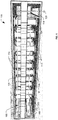
- FIG. 1 is a diagram of a first particular embodiment of a heat exchange device, generally referenced 100.
- the heat exchange device 100 includes a housing (only partially shown) including a first side 102 and a second side 104.
- the housing also includes an inlet 112 and an outlet 114.
- One or more ceramic foam members 106 are disposed within the housing (e.g., between the first side 102 and the second side 104).
- the one or more ceramic foam members 106 define a plurality of pores through which a coolant 120 can pass.
- the one or more ceramic foam members 106 may include a plurality of irregularly oriented ceramic fibers with openings between them through which the coolant 120 can flow providing a large surface area for thermal transfer.
- the one or more ceramic foam members 106 may include one or more of the ceramic foams described with reference to FIG. 3 .
- the heat exchange device 100 may also include a plurality of extended plugs 108 that extend from the first side 102 of the housing to the second side 104 of the housing through the one or more ceramic foam members 106.
- the first side 102 of the housing is spaced apart from the one or more ceramic foam members 106 by a first end of the plurality of extended plugs 108.
- the one or more ceramic foam members 106 and the first side 102 of the housing define a first channel 160 through which the coolant 120 passes in contact with the one or more extended plugs 108.
- the second side 104 of the housing may be spaced apart from the one or more ceramic foam members 106 by second ends of the plurality of extended plugs 108.
- the second side 104 of the housing and the one or more ceramic foam members 106 may define a second channel 162 through which the coolant 120 flows in contact with the plurality of extended plugs 108.
- the one or more ceramic foam members 106 and the plurality of extended plugs 108 together may be referred to as a heat exchanger core or as a cold plate.
- one or more sides of the housing may be thermally conductive to facilitate transfer of heat from outside the housing to the coolant 120.
- the first side 102 of the housing may be thermally conductive to receive heat from a heat source (not shown) and to transfer the heat to the plurality of extended plugs 108.
- one or more sides of the housing may be thermally insulating to reduce transfer of heat from the coolant 120 to outside the housing.
- the second side 104 of the housing may be thermally insulating to reduce heat transfer from the coolant 120 to the underlying structure.
- the second side 104 may be formed of a ceramic foam.
- the second side 104 may be formed of the same material as the one or more ceramic foam members 106.
- one or more sides of the housing may be erosion resistant.
- the first side 102 may include an erosion resistant layer to enable the heat exchange device 100 to operate in harsh exterior environment of the aircraft.
- the first side 102 of the housing may include a plurality of alumina silica fibers embedded with an aluminum nitride material to form a thermally conductive, erosion resistant layer.
- the thermally conductive, erosion resistant layer may be formed by impregnating an alumina-silica cloth, sheet or mat (such as Nitivy ALFTM fibers available from Nitivy Company Limited of Tokyo, Japan) with a castable aluminum nitride material (such as Aremco CeramacastTM 675N (“Ceramacast 675N”), available from Aremco Products, Inc. of Valley Cottage, NY) and curing the castable aluminum nitride material.
- alumina-silica cloth, sheet or mat such as Nitivy ALFTM fibers available from Nitivy Company Limited of Tokyo, Japan
- a castable aluminum nitride material such as Aremco CeramacastTM 675N (“Ceramacast 675N"), available from Aremco Products, Inc. of Valley Cottage, NY
- the plurality of extended plugs 108 have a low electrical conductivity.
- the plurality of extended plugs 108 may include aluminum nitride rods that extend from the first side 102 of the housing to the second side 104 of the housing through the one or more ceramic foam members 106. Other materials with thermal and electrical conductivity properties similar to aluminum nitride may also be used.
- the plurality of extended plugs 108 may be formed using a castable aluminum nitride material.
- the extended plugs 108 are coupled to the first side 102 and to the second side 104 of the housing via a thermally conductive adhesive 110.
- the thermally conductive adhesive 110 may include a room temperature vulcanizing (RTV) adhesive.
- RTV room temperature vulcanizing
- the first side 102 and the second side 104 of the housing may be bonded to the extended plugs 108 using the castable aluminum nitride material.
- the heat exchange device 100 may also include a coolant impermeable dam 124 on an inlet side of the heat exchange device 100.
- the inlet side of the heat exchange device may refer to a side of the heat exchange device 100 including the second channel 162.
- the coolant impermeable dam 124 may prevent the coolant 120 received via the inlet 112 from flowing directly to the outlet 114, forcing the coolant 120 to flow through the one or more ceramic foam members 106 to the first channel 160.
- the inlet 112 is illustrated as located on an end of the heat exchange device (i.e., a plane of the inlet 112 is transverse to a plane of the second side 104 of the housing).
- the inlet 112 may be located in another position, such as through the second side 104 of the housing (i.e., such that a plane of the inlet 112 is parallel with a plane of the second side 104).
- the outlet 114 in FIG. 1 is illustrated as located on the second side 104 of the housing (i.e., a plane of the outlet 114 is parallel to a plane of the second side 104 of the housing).
- the outlet 114 may be located in another position, such as through an end of the housing (i.e., such that a plane of the outlet 114 is perpendicular to a plane of the second side 104).
- the coolant 120 may be received via the inlet 112 into the second channel 162 of the heat exchange device 100. Since the coolant impermeable dam 124 inhibits the coolant 120 from flowing from the inlet 112 directly to the outlet 114, a pressure differential between the second channel 162 and the first channel 160 may drive the coolant 120 to flow through a thickness of the one or more ceramic foam members 106, as illustrated by coolant flow 122 to the first channel 160. The coolant 120 may flow into the first channel 160, as illustrated by coolant flow 126 and to the outlet 114 as illustrated by coolant flow 128.
- the coolant 120 may include ram air.
- the coolant 120 may be processed before being routed to the heat exchange device 100.
- a temperature or pressure of the coolant 120 may be modified before the coolant 120 is routed to the heat exchange device 100.
- heat received via the first side 102 of the housing may be transferred to the plurality of extended plugs 108 via the thermally conductive adhesive 110.
- the coolant 120 received at the inlet 112 may flow in contact with the plurality of extended plugs 108 in the second channel 162.
- the coolant 120 may pass through pores of the one or more ceramic foam members 106 (as shown at the coolant flow 122).
- the coolant 120 may also flow in contact with the plurality of extended plugs 108 in the first channel 160 to the outlet 114 (as shown at the coolant flows 126 and 128).
- Heat may be transferred to the coolant 120 by the plurality of extended plugs 108; by contact with sides of the housing 102, 104; and by contact with the one or more ceramic foam members 106.
- thermal protection and surface temperature control in the presence of a high flux heat source may be achieved by using a plurality of extended plugs 108 to transfer heat to the one or more ceramic foam members 106 so that the coolant 120 may contact the relatively high surface area of the ceramic foam member 106 to extract the heat.
- a heat source may be on the first side 102 of the housing.
- the heat source may include a printed circuit board or other electronic device, such as an avionics component.
- the heat source may include an exterior surface of an aircraft, such as a leading edge or other surface subjected to a high heat load or a surface on a propulsion flow path (such as an engine exhaust nozzle).
- the coolant 120 flows from the inlet 112 to the outlet 114 through the channels 160 and 162, a reduction in the overall volume and in the weight of the materials required for plenums may be achieved since the channels 160 and 162 provide routing of the coolant where plenums would otherwise be used (e.g., for back side cooling systems or film cooling systems).
- FIG. 2 is a diagram of a second particular embodiment of a heat exchange device, generally referenced 200.
- the heat exchange device 200 includes a housing (only partially shown) including a first side 202 and a second side 204.
- the housing also includes an inlet 212 and an outlet 214.
- One or more ceramic foam members 206 are disposed within the housing (e.g., between the first side 202 and the second side 204).
- the one or more ceramic foam members 206 define a plurality of pores through which a coolant 220 can pass.
- the ceramic foam member(s) 206 may include a plurality of irregularly oriented ceramic fibers with openings between them through which the coolant 220 can flow providing a large surface area for thermal transfer.
- the ceramic foam member(s) 206 include one or more of the ceramic foams describe with reference to FIG. 3 .
- the heat exchange device 200 may also include a plurality of extended plugs 208 that extend from the first side 202 of the housing to the second side 204 of the housing through the one or more ceramic foam members 206.
- the first side 202 of the housing is spaced apart from the one or more ceramic foam members 206 by a first end of the plurality of extended plugs 208.
- the one or more ceramic foam members 206 and the first side 202 of the housing define a first channel 260 through which the coolant 220 passes in contact with the one or more extended plugs 208.
- the second side 204 of the housing may be spaced apart from the one or more ceramic foam members 206 by second ends of the plurality of extended plugs 208. Accordingly, the second side 204 of the housing and the one or more ceramic foam members 206 may define a second channel 262 through which the coolant 220 flows in contact with the plurality of extended plugs 208.
- one or more sides of the housing are thermally conductive to facilitate transfer of heat from a heat source outside the housing to the coolant 220.
- the first side 202 of the housing may be thermally conductive to receive heat from the heat source and to transfer the heat to the plurality of extended plugs 208.
- one or more sides of the housing are thermally insulating to reduce transfer of heat from the coolant 220 to outside the housing.
- the second side 204 of the housing may be thermally insulating to reduce heat transfer from the coolant 220 to the underlying structure.
- the second side 204 may be formed of a ceramic foam.
- the second side 204 may be formed of the same material as the one or more ceramic foam members 206.
- one or more sides of the housing may be erosion resistant.
- the first side 202 may include an erosion resistant layer to enable the heat exchange device 200 to operate in a harsh exterior environment of the aircraft.
- the first side 202 of the housing may include a plurality of alumina silica fibers embedded with an aluminum nitride material to form thermally conductive, erosion resistant layer.
- the thermally conductive, erosion resistant layer may be formed by embedding alumina-silica fibers, cloth, sheet or mat (such as Nitivy ALFTM fibers available from Nitivy Company Limited of Tokyo, Japan) with a castable aluminum nitride material (such as Ceramacast 675N) and curing the castable aluminum nitride material.
- alumina-silica fibers, cloth, sheet or mat such as Nitivy ALFTM fibers available from Nitivy Company Limited of Tokyo, Japan
- a castable aluminum nitride material such as Ceramacast 675N
- the plurality of extended plugs 208 have a low electrical conductivity.
- the plurality of extended plugs 208 may include aluminum nitride rods that extend from the first side 202 of the housing to the second side 204 of the housing through the one or more ceramic foam members 206. Other materials with thermal and electrical conductivity properties similar to aluminum nitride may also be used.
- the plurality of extended plugs 208 may be formed using a castable aluminum nitride material.
- the plurality of extended plugs 208 is coupled to the first side 202 and to the second side 204 of the housing via a thermally conductive adhesive 210.
- the thermally conductive adhesive 210 may include a room temperature vulcanizing (RTV) adhesive.
- RTV room temperature vulcanizing
- the first side 202 and the second side 204 of the housing may be bonded to the extended plugs 208 using the castable aluminum nitride material.
- the heat exchange device 200 may also include a coolant impermeable dam 224 in the second channel 262 between an inlet side 252 of the heat exchange device 200 and an outlet side 254 of the heat exchange device 200.
- the inlet side 252 of the heat exchange device 200 may refer to a side of the heat exchange device 200 including the inlet 212 and a first portion of the second channel 262.
- the outlet side 254 of the heat exchange device 200 may refer to a side of the heat exchange device 200 including the outlet 214 and a second portion of the second channel 262. In the embodiment illustrated in FIG.
- the inlet side 252 of the heat exchange device 200 includes the portion of the second channel 262 including an area between the inlet 212, the one or more ceramic foam members 206, the second side 204 of the housing, and the coolant impermeable dam 224.
- the outlet side 254 of the heat exchange device 200 includes the portion of the second channel 262 including an area between the outlet 214, the one or more ceramic foam members 206, the second side 204 of the housing, and the coolant impermeable dam 224.
- the coolant impermeable dam 224 forces the coolant 220 received via the inlet 212 to flow through the one or more ceramic foam members 206 in a first direction (toward the first side 202 of the housing) and to flow through the one or more ceramic foam members 206 in a second direction (toward the second side 204 of the housing) to the outlet 214. Since the coolant 220 passes through pores of the one or more ceramic foam members 206 twice, the embodiment illustrated in FIG. 2 may be referred to as a two pass configuration of the heat exchange device 200. Increased thermal efficiency may be achieved by the two pass configuration as compared to single pass configurations where the coolant 220 only passes through the pores of the one or more ceramic foam members 206 once.
- the inlet 212 is illustrated as located on an end of the heat exchange device 200 (i.e., a plane of the inlet 212 is perpendicular to a plane of the second side 204 of the housing). However, in other embodiments, the inlet 212 is located in another position, such as through the second side 204 of the housing (i.e., such that the plane of the inlet 212 is parallel with the plane of the second side 204). Additionally, the outlet 214 in FIG. 2 is illustrated as located on the second side 204 of the housing (i.e., a plane of the outlet 214 is parallel to the plane of the second side 204 of the housing). However, in other embodiments, the outlet 214 may be located in another position, such as through an end of the housing (i.e., such that the plane of the outlet 214 is perpendicular to the plane of the second side 204).
- the coolant 220 may be received via the inlet 212 into the second channel 262. Since the coolant impermeable dam 224 inhibits the coolant 220 from flowing from the inlet 212 directly to the outlet 214, a pressure differential between the second channel 262 and the first channel 260 may force the coolant 220 to flow through a thickness of the one or more ceramic foam members 206, as illustrated by coolant flow 222. The coolant 220 may flow in the first channel 260 as illustrated by coolant flow 226. A pressure differential between the first channel 260 and the outlet side 254 of the second channel 262 may force the coolant 220 to flow through the thickness of the one or more ceramic foam members 206 in a second direction, as illustrated by coolant flow 230, to the outlet side 254. The coolant 220 may flow within the outlet side 254 to the outlet 214 and exit the heat exchange device 200 via the outlet 214, as illustrated by coolant flow 228.
- the coolant 220 includes ram air. In other embodiments, the coolant 220 may include another cooling fluid, either liquid or gas.
- the coolant 220 may be processed before being routed to the heat exchange device 200. For example, a temperature or pressure of the coolant 220 may be modified before the coolant 220 is routed to the heat exchange device 200.
- heat received via the first side 202 of the housing is transferred to the plurality of extended plugs 208 via the thermally conductive adhesive 210.
- the coolant 220 received at the inlet 212 may flow in contact with the plurality of extended plugs 208 on the inlet side 252 of the second channel 262.
- the coolant 220 may pass through the pores of the one or more ceramic foam members 206 in the first direction as shown by the coolant flow 222.
- the coolant 220 may also flow in contact with the plurality of extended plugs 208 in the first channel 260 as shown by the coolant flow 226.
- the coolant 220 may pass through the pores of the one or more ceramic foam members 206 in the second direction as shown by the coolant flow 230.
- the coolant may flow in contact with the plurality of extended plugs 208 as shown by the coolant flow 232 and out of the heat exchange device 200 via the outlet 214 as shown by the coolant flow 228.
- Heat may be transferred to the coolant 220 by the plurality of extended plugs 208; by contact with sides of the housing 202, 204; and by contact with the one or more ceramic foam members 206 as the coolant 220 flows through pores of the one or more ceramic foam members 206 in both directions. Accordingly, a high rate of heat transfer and a greatly reduced surface temperature at the first side 202 may be achieved at a relatively low coolant pressure drop.
- thermal protection and surface temperature control in the presence of a high flux heat source may be achieved by using a plurality of extended plugs 208 to transfer heat to the one or more ceramic foam members 206 so that the coolant 220 may contact the relatively high surface area of the ceramic foam member 206 to absorb heat.
- a heat source may be on the first side 202 of the housing.
- the heat source may include a printed circuit board or other electronic device, such as an avionics component.
- the heat source may include an exterior surface of an aircraft, such as a leading edge or other surface subjected to a high heat load or a surface in a propulsion flow path, such as an engine exhaust nozzle.
- the coolant 220 flows from the inlet 212 to the outlet 214 through the channels 260 and 262, a reduction in the overall volume and in the weight of the materials required for plenums may be achieved.
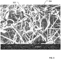
- FIG. 3 is an illustration of a particular embodiment of a ceramic foam for a heat exchange device.
- the ceramic foam illustrated in FIG. 3 may be used to form a ceramic foam member, such as the one or more ceramic foam members 106 of FIG. 1 or the one or more ceramic foam members 206 of FIG. 2 .
- FIG. 3 illustrates an electron micrograph of fibers 302 of Alumina Enhanced Thermal Barrier (AETB), made by The Boeing Company, Huntington Beach, Calif.
- FIG. 3 also illustrates that pores 304 of the ceramic foam may have an average pore size of approximately 35 micrometers.
- Another ceramic foam material that may be used is Boeing Rigid Insulation foam (BRI) also available from The Boeing Company, Huntington Beach, Calif.
- BBI Boeing Rigid Insulation foam
- the ceramic foam may include materials that combine small average pore size and high porosity.
- the ceramic foam includes an alumina silica ceramic foam with up to around 68 percent silica, around 20 percent alumina, and around 12 percent alumina borosilicate fibers.
- the ceramic foam may include an alumina silica foam that is light-weight having a density of approximately 256 kg/m 3 (16 pounds per cubic foot).
- the porosity of the ceramic foam may be in excess of 80 percent. In a particular embodiment, the porosity may be at least 90 percent.
- the pores of the ceramic foam may be between 5 and 50 microns across with an average pore size of about 35 microns.
- the combination of high porosity and very small pores provides a large internal surface area for transfer of heat to a coolant flowing through the pores of the ceramic foam.
- the internal surface area of the ceramic foam may be approximately 31,350 ft 2 /ft 3 (102,85 m 2 /m 3 ).
- the pores of the ceramic foam have an average diameter of less than 50 microns, so air flow through the ceramic foam becomes rarefied. Air flow in ceramic foam at the pressure levels characteristic of the embodiments disclosed herein results in the flow being in the slip flow regime. Rarefaction of the coolant flow (i.e., flow within the slip flow regime) occurs when the flow channel size, in this case the effective diameter of the pores, approaches the mean free path of the individual molecules in the coolant flow. In rarefied flow, the flow can no longer be considered as a continuum and is more correctly considered in terms of the path of individual particles through the flow channel. Since no boundary layer is formed, the coolant has a non-zero "slip" velocity at the walls of the flow channels.
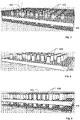
- FIGS. 4-9 illustrate a particular embodiment of a method of manufacturing an extended plug cold plate.
- the method illustrated in FIGS. 4-9 may be used to manufacture the heat exchange device 100 illustrated in FIG. 1 or the heat exchange device 200 illustrated in FIG. 2 .
- a ceramic foam member 406 is provided.
- the ceramic foam member 406, such as the ceramic foam illustrated in FIG. 3 may include a plurality of pores defined by spaces between ceramic fibers.
- a first casting layer 434 is applied to a first side of the ceramic foam member 406 and a second casting layer 436 is applied to a second side of the ceramic foam member 406.
- the first casting layer 434 and the second casting layer 436 may include a wax layer, a silicone layer, or a layer of another material that can be applied to and removed from the ceramic foam member 406 without damaging extended plugs (such as the extended plugs 108 of FIG. 1 or the extended plugs 208 of FIG. 2 ) formed through the ceramic foam member 406.
- the casting layers 434 and 436 should also be capable of being modified to provide openings for casting the extended plugs.
- a plurality of openings 432 are provided through the first casting layer 434, the ceramic foam member 406, and the second casting layer 436.
- the openings 432 may be drilled or otherwise machined through the first casting layer 434, the ceramic foam member 406, and the second casting layer 436.
- a casting material 440 may be pored or injected into the openings 432.
- the casting material 440 may be curable to form a thermally conductive material.
- the casting material 440 may include a castable aluminum nitride, such as Ceramacast 675N.
- the casting material 440 may be cured to form a plurality of thermally conductive extended plugs 408 through the ceramic foam member 406.
- the first casting layer 434 and the second casting layer 436 may be removed leaving the ceramic foam member 406 and the plurality of cured thermally conductive extended plugs 408 as a cold plate core.
- a thermally conductive adhesive 410 may be used to apply a first side 402 of a housing to first ends of the plurality of thermally conductive extended plugs 408. Additionally, the thermally conductive adhesive 410 may be used to apply a second side 404 of the housing to second ends of the plurality of thermally conductive extended plugs 408.
- the thermally conductive adhesive may include a thermally conductive room temperature vulcanizing (RTV) adhesive. In another example, the thermally conductive adhesive may include the casting material 440.
- the first side 402, the second side 404, or both may be thermally conductive.
- first side 402 or the second side 404 may be thermally insulating. Additionally, the first side 402, the second side 404, or both may have low electrical conductivity (e.g., a dielectric constant about 8.8). Further, an erosion resistant layer may be applied to the first side 402, the second side 404, or both.
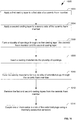
- FIG. 10 is a flowchart of a particular embodiment of a method of manufacturing a heat exchange core.
- the method is generally designated 1000.
- the method 1000 may be used to manufacture the heat exchange device 100 of FIG. 1 , or the heat exchange device 200 of FIG. 2 .
- the method 1000 includes, at 1002, applying a first casting layer to a first side of a ceramic foam member.
- the method 1000 also includes, at 1004, applying a second casting layer to a second side of the ceramic foam member.
- the ceramic foam member may be a high porosity foam with a porosity of about 90 percent and an average pore size of about 35 microns across, such as the ceramic foam described with reference to FIG. 3 .
- the first and second casting layers may include a material that can be applied to and removed from the ceramic foam, in which casting openings can be formed and that is capable of retaining a casting material during curing of the casting material.
- the first and second casting layers may include wax or silicone.
- the method 1000 also includes, at 1006, forming a plurality of openings through the first casting layer, the ceramic foam member and the second casting layer.
- the openings may be formed by drilling or otherwise machining openings through the first casting layer, the ceramic foam member and the second casting layer.
- the method 1000 may further include, at 1008, inserting a casting material into the plurality of openings.
- the casting material may include a curable aluminum nitride material or other curable thermally conductive materials.
- the method 1000 may also include, at 1010, curing the casting material to form a plurality of thermally conductive extended plugs through the ceramic foam member.
- the method 1000 may also include, at 1012, removing the first and second casting layers from the ceramic foam member.
- the plurality of thermally conductive extended plugs and the ceramic foam member form the heat exchange core.
- a heat exchange device such as a cold plate or thermal protection system, may be formed, at 1014, by coupling one or more sides to ends of the extended plugs using a thermally conductive adhesive to form a housing.
- FIG. 11 is a flowchart of a particular embodiment of a heat exchange method.
- the method is generally designated 1100.
- the method 1100 may be performed using a heat exchange device, such as the heat exchange device 100 of FIG. 1 , the heat exchange device 200 of FIG. 2 , a heat exchange device manufactured using the method illustrated in FIGS. 4-9 , or a heat exchange device manufactured using the method 1000 of FIG. 10 .
- the method 1100 includes receiving ram air from outside an aircraft, at 1102.
- the ram air may be received via one or more inlet ports or via an airstream diverted from an engine inlet.
- the ram air may be further pressurized, at 1104, or otherwise treated, such as by pre-cooling the ram air before the ram air is routed for use as a coolant.
- a coolant other than ram air may be used.
- a liquid coolant may be used or a gaseous coolant other than ram air may be used.
- a phase-changing refrigerant material may be used as the coolant.
- the method 1100 may also include, at 1106, routing the ram air to an inlet of a heat exchange device (e.g., a cold plate) as a coolant.
- a heat exchange device e.g., a cold plate
- heat may be extracted from a surface to be cooled into the coolant routed through the inlet of the heat exchange device.
- the heat exchange device may be adjacent to a surface to be cooled.
- the heat exchange device may be adjacent to a heat exposed surface, such as an engine exhaust nozzle or a leading edge of the aircraft.
- the heat exchange device may be adjacent to a heat generating device, such as a printed circuit board or other electronic device such as an avionics device.
- the heat exchange device may include the inlet, an outlet and a ceramic foam member spaced apart from the surface to be cooled.
- the ceramic foam member may include a high porosity foam, such as the ceramic foam described with reference to FIG. 3 .
- a plurality of thermally conductive extended plugs may extend from a first side of a ceramic foam member adjacent to the inlet through the ceramic foam member to the surface to be cooled.
- the coolant that is routed to the inlet may pass from the inlet to a space (or channel) between the ceramic foam member and the surface to be cooled through pores of the ceramic foam member.
- the coolant may pass through the space between the ceramic foam member and the surface to be cooled to an outlet of a heat exchange device. In a particular embodiment, the coolant may pass a second time through pores of the ceramic foam member prior to reaching the outlet.
- FIG. 12 is a diagram of a particular embodiment of an aircraft 1200 including one or more heat exchange devices.
- the heat exchange devices may include the heat exchange device 100 illustrated in FIG. 1 , the heat exchange device 200 illustrated in FIG. 2 , or a combination thereof.
- the aircraft 1200 may also include at least one engine 1206, a fuselage 1220, and a plurality of wings or other lift generating surfaces 1222.
- the aircraft 1200 includes one or more surfaces that are exposed to high heat flux.
- the surfaces experiencing heating may include an exterior surface of the aircraft.
- the heat exposed surfaces may include a surface 1202 that may be heated due to frictional contact with surrounding air, especially during high-speed flight.
- the heat exposed surfaces may include a surface of an engine exhaust nozzle 1208 of the at least one engine 1206.
- the exhaust nozzle 1208 may include one or more heat exposed surfaces (not shown), such as interior surfaces of the exhaust nozzle 1208.
- the heat exchange devices of the aircraft 1200 may include one or more cold plates adjacent to the heat exposed surfaces.
- a first cold plate 1204 may be adjacent to the first heat exposed surface 1202.
- the first cold plate 1204 may be adapted to remove heat from the first heat exposed surface 1202.
- a second cold plate 1210 may be located at or adjacent to the exhaust nozzle 1208 of one or more engines 1206.
- the cold plates 1204 and 1210 include an inlet to receive a coolant and an outlet to route the coolant away from the cold plates 1204 and 1210.
- the cold plates 1204 and 1210 may also include one or more ceramic foam members inside the cold plates 1204 and 1210. The one or more ceramic foam members define a plurality of pores.
- the one or more ceramic foam members may include a ceramic foam as described with reference to FIG. 3 .
- the cold plates 1204 and 1210 may also include a plurality of thermally conductive extended plugs that extend from a first side of the cold plate separated from the heat exposed surface through the ceramic foam member to a second side of the cold plate adjacent to the heat exposed surface. The second side of a heat exposed surface may be separated from the ceramic foam member by ends of the thermally conductive extended plugs.
- the heat exposed surface may include a thermally conductive erosion resistant layer that is thermally coupled to first ends of the plurality of thermally conductive extended plugs.
- FIGS. 13 and 14 are charts of simulated performance characteristics of heat exchange devices according to particular embodiments.
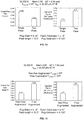
- FIG. 13 includes two charts of simulated performance characteristics of the heat exchange device 100 illustrated in FIG. 1 , referred to in FIG. 13 as a "single pass" configuration, and the heat exchange device 200 illustrated in FIG. 2 , referred to in FIG. 13 as a "two pass” configuration.
- the performance characteristics are simulated for the heat exchange devices using ram air as the coolant, where the ram air is received at flight conditions including an altitude of 9144 m (30,000 feet) and a speed of Mach 0.8.
- the ram air temperature is estimated to be -15 °C (5 °F).
- An allowable coolant pressure drop based on ram air for these flight conditions is set to 0.94 pounds per square inch (psid) (6.5 kN/m 2 ). Additionally, the heat transfer coefficient (h surf ) for a high heat flux surface of the aircraft is set at 20 BTU/hr-ft - °F.
- the performance characteristics are simulated for the heat exchange devices based on a six inch long cold plate that has been analytically extended to twelve inches long for both a single pass and a two pass design.
- the simulated heat exchange devices include extended plugs arranged in a row with approximately 6.223 mm (0.245 inches) between rows and extended plugs in each row set at about 12.446 mm (0.49 inches) on center.
- Each thermally conductive extended plug had a diameter (Plug Diam) of 3.556 mm (0.14 inches) and extended past the ceramic foam member (Plug Extension) by approximately 3.175 mm (0.125 inches).
- the ceramic foam member had a thickness (Foam Thickness) of approximately 3.81 mm (0.15 inches), and the total length of the cooling device (Plate Length) was 12 inches.
- the expected coolant flow rate in pounds per second per square foot (Lb/sec- ft 2 ) for the single pass configuration is approximately 0.038 (0.185 kg/(s m 2 )) and for the two pass configuration is approximately 0.034 (0.166 kg/(s m 2 )).
- the two pass configuration may achieve desired cooling with a lower coolant flow rate.
- FIG. 13 also illustrates a simulated equivalent fan air film cooling effectiveness for each configuration of the heat exchange device.
- the equivalent fan air film cooling effectiveness relates the temperature achieved at the interface between an extended plug cold plate and a hot gas to the corresponding film cooling effectiveness.
- the equivalent fan air film cooling effectiveness is approximately 0.73 and for the two pass configuration the equivalent fan air film cooling effectiveness is approximately 0.77.
- the two pass cold plate produces a greater degree of cooling with less coolant flow than is the case for the single pass cold plate.
- FIG. 14 includes two charts of simulated performance characteristics of the two pass cold plate 200 illustrated in FIG. 2 .
- FIG. 14 illustrates additional improvements that can be achieved using the two pass configuration when the ram air is augmented, by increasing the ram air supply pressure. Augmenting the ram air may increase the coolant flow rate significantly, further improving the equivalent fan air film cooling effectiveness of the two pass configuration of the heat exchange device by reducing the surface temperature.
- the simulated performance data illustrated in FIG. 14 compares a non-flow augmented case to a flow augmented case for both coolant flow rate and equivalent fan air film cooling effectiveness. This comparison is made using the two pass cold plate configuration and vehicle flight condition defined with reference to FIG. 13 .
- Flow augmentation through pressurization of the ram air coolant results in an increase in supply pressure of 1.0 psi to an 1.94 (6.9 - 13.4 kN/m 2 ) coolant flow pressure drop and an increase in supply temperature to -9.44 °C (15 °F).
- Flow augmentation results in an increase in coolant flow to 0.2684 kg/(s m 2 ) (0.055 lbs/sec-ft2) from 0.166 kg/(s m2) (0.034 lbs/sec-ft2) for the non-flow augmented case.
- This increase in coolant flow leads to an increase in equivalent fan air film cooling effectiveness to 0.84 from 0.77 for the non-flow augmented case.
- the heat exchange devices disclosed herein are not limited to use in aircraft. Rather, any vehicle that uses a heat exchange device for thermal protection, cooling of components or for other purposes may benefit from the reduced equipment and operation costs associated with the disclosed heat exchange devices.
- spacecraft, land-based vehicles, and water-based vehicles may benefit from use of the disclosed heat exchange devices to provide thermal protection and heat management.
- the disclosed heat exchange devices may provide reduced equipment cost and reduced operating cost for non-mobile uses, such as thermal management in buildings or other structures.
- different coolants may be used depending on operational constraints of the system being cooled. To illustrate, for stationary or slow moving systems, air cooling may not be sufficient. Accordingly a liquid or phase-change coolant may be used.
- the heat exchange devices disclosed may similarly be used for heating. That is, rather that using a relatively cold material (e.g., a coolant) to remove heat from a heat source via a surface of a heat exchange device, the heat exchange device may receive heat from a relatively hot material and provide the heat to a heat sink via the surface of the heat exchange device.
- a relatively cold material e.g., a coolant
Landscapes
- Engineering & Computer Science (AREA)
- Chemical & Material Sciences (AREA)
- Dispersion Chemistry (AREA)
- Physics & Mathematics (AREA)
- Thermal Sciences (AREA)
- Mechanical Engineering (AREA)
- General Engineering & Computer Science (AREA)
- Cooling Or The Like Of Electrical Apparatus (AREA)
- Heat-Exchange Devices With Radiators And Conduit Assemblies (AREA)
Applications Claiming Priority (1)
| Application Number | Priority Date | Filing Date | Title |
|---|---|---|---|
| US12/630,699 US8720828B2 (en) | 2009-12-03 | 2009-12-03 | Extended plug cold plate |
Publications (3)
| Publication Number | Publication Date |
|---|---|
| EP2333475A2 EP2333475A2 (en) | 2011-06-15 |
| EP2333475A3 EP2333475A3 (en) | 2013-05-01 |
| EP2333475B1 true EP2333475B1 (en) | 2018-09-12 |
Family
ID=43587122
Family Applications (1)
| Application Number | Title | Priority Date | Filing Date |
|---|---|---|---|
| EP10193280.4A Not-in-force EP2333475B1 (en) | 2009-12-03 | 2010-12-01 | Cold plate comprising ceramic foam member |
Country Status (4)
| Country | Link |
|---|---|
| US (1) | US8720828B2 (enExample) |
| EP (1) | EP2333475B1 (enExample) |
| JP (1) | JP5730552B2 (enExample) |
| CN (1) | CN102095314B (enExample) |
Families Citing this family (8)
| Publication number | Priority date | Publication date | Assignee | Title |
|---|---|---|---|---|
| RU2481255C2 (ru) * | 2011-08-05 | 2013-05-10 | Открытое акционерное общество "Информационные спутниковые системы" имени академика М.Ф. Решетнева" | Способ изготовления системы терморегулирования космического аппарата |
| JP5953206B2 (ja) * | 2011-11-11 | 2016-07-20 | 昭和電工株式会社 | 液冷式冷却装置およびその製造方法 |
| US9182175B2 (en) | 2011-12-01 | 2015-11-10 | The Boeing Company | Anti-icing heat exchanger |
| US9074829B2 (en) | 2011-12-01 | 2015-07-07 | The Boeing Company | Lightweight high temperature heat exchanger |
| US9403600B2 (en) | 2012-05-01 | 2016-08-02 | Lockheed Martin Corporation | Integrated thermal protection and leakage reduction in a supersonic air intake system |
| JP6447630B2 (ja) | 2014-08-13 | 2019-01-09 | 株式会社Ihi | 航空機の電子機器を冷却する冷却装置 |
| CN106570252B (zh) * | 2016-10-26 | 2019-05-24 | 中国运载火箭技术研究院 | 一种基于概率技术的热防护系统设计方法 |
| US12319117B2 (en) | 2023-04-27 | 2025-06-03 | Pratt & Whitney Canada Corp. | Heat exchanger and method of operation |
Family Cites Families (64)
| Publication number | Priority date | Publication date | Assignee | Title |
|---|---|---|---|---|
| CH427118A (de) | 1963-11-28 | 1966-12-31 | Bbc Brown Boveri & Cie | Verfahren zum Schützen von durch heisse Medien überstrichenen Oberflächenteilen eines hitzebeständigen Körpers |
| US3452553A (en) | 1967-03-17 | 1969-07-01 | Gen Dynamics Corp | Transpiration cooled window |
| US3880969A (en) | 1973-11-05 | 1975-04-29 | Universal Oil Prod Co | Method of preparing an open-celled aromic foam |
| US4222434A (en) * | 1978-04-27 | 1980-09-16 | Clyde Robert A | Ceramic sponge heat-exchanger member |
| US4420462A (en) | 1982-03-22 | 1983-12-13 | Clyde Robert A | Catalytic heat exchanger |
| JPS6078143U (ja) * | 1983-10-31 | 1985-05-31 | 三菱電機株式会社 | 液冷装置 |
| US4884168A (en) | 1988-12-14 | 1989-11-28 | Cray Research, Inc. | Cooling plate with interboard connector apertures for circuit board assemblies |
| US4884169A (en) | 1989-01-23 | 1989-11-28 | Technology Enterprises Company | Bubble generation in condensation wells for cooling high density integrated circuit chips |
| US5744252A (en) | 1989-09-21 | 1998-04-28 | The United States Of America As Represented By The Administrator Of The National Aeronautics And Space Administration | Flexible ceramic-metal insulation composite and method of making |
| JPH07114250B2 (ja) | 1990-04-27 | 1995-12-06 | インターナショナル・ビジネス・マシーンズ・コーポレイション | 熱伝達システム |
| ATE163474T1 (de) * | 1991-04-15 | 1998-03-15 | Scient Ecology Group Inc | Wärmetauscher für sehr hohe temperatur |
| JPH0731028B2 (ja) * | 1991-05-24 | 1995-04-10 | 株式会社ヒラノテクシード | 熱風供給方法、及び放熱装置 |
| JP2995590B2 (ja) | 1991-06-26 | 1999-12-27 | 株式会社日立製作所 | 半導体冷却装置 |
| JPH05136305A (ja) | 1991-11-08 | 1993-06-01 | Hitachi Ltd | 発熱体の冷却装置 |
| US6006824A (en) * | 1994-03-28 | 1999-12-28 | Ngk Insulators, Ltd. | Ceramic shell-and-tube type heat exchanger, and method for manufacturing it |
| JPH09253945A (ja) * | 1996-03-25 | 1997-09-30 | Ngk Insulators Ltd | フィン付きセラミック製シェルアンドチューブ型熱交換器及びその製造方法 |
| DE19643717A1 (de) | 1996-10-23 | 1998-04-30 | Asea Brown Boveri | Flüssigkeits-Kühlvorrichtung für ein Hochleistungshalbleitermodul |
| JPH10148120A (ja) | 1996-11-18 | 1998-06-02 | Isuzu Ceramics Kenkyusho:Kk | 給電用エンジンの熱回収装置 |
| US6089505A (en) | 1997-07-22 | 2000-07-18 | Mcdonnell Douglas Corporation | Mission adaptive inlet |
| JPH11254047A (ja) * | 1998-03-12 | 1999-09-21 | Konica Corp | 熱交換器に使用する薄板の曲げ方法及び熱交換器 |
| JP4067165B2 (ja) * | 1998-03-23 | 2008-03-26 | 電気化学工業株式会社 | 複合体とそれを用いたヒートシンク |
| WO1999052838A1 (en) | 1998-04-13 | 1999-10-21 | Minnesota Mining And Manufacturing Company | Tough, low permeable ceramic composite material |
| US6196307B1 (en) | 1998-06-17 | 2001-03-06 | Intersil Americas Inc. | High performance heat exchanger and method |
| AU4687799A (en) | 1998-06-19 | 2000-01-05 | Zess Technologies, Inc. | Micro-channel heat exchanger |
| KR20010076991A (ko) | 2000-01-29 | 2001-08-17 | 박호군 | 발포금속 방열기 |
| US6761211B2 (en) | 2000-03-14 | 2004-07-13 | Delphi Technologies, Inc. | High-performance heat sink for electronics cooling |
| US6840307B2 (en) | 2000-03-14 | 2005-01-11 | Delphi Technologies, Inc. | High performance heat exchange assembly |
| US6478082B1 (en) | 2000-05-22 | 2002-11-12 | Jia Hao Li | Heat dissipating apparatus with nest wind duct |
| KR100468217B1 (ko) * | 2001-12-31 | 2005-01-26 | 한국과학기술연구원 | 다공성 금속물질을 이용한 축방열 시스템 |
| JP2005516425A (ja) * | 2002-01-30 | 2005-06-02 | エレル,デイビット | フィン対空気の接触面積が大きいヒートシンク |
| US6888720B2 (en) | 2002-06-18 | 2005-05-03 | Sun Microsystems, Inc. | Distributed graphitic foam heat exchanger system |
| US6988534B2 (en) | 2002-11-01 | 2006-01-24 | Cooligy, Inc. | Method and apparatus for flexible fluid delivery for cooling desired hot spots in a heat producing device |
| US6757170B2 (en) | 2002-07-26 | 2004-06-29 | Intel Corporation | Heat sink and package surface design |
| US6735083B2 (en) | 2002-08-07 | 2004-05-11 | Inventec Corporation | Porous CPU cooler |
| KR100917042B1 (ko) * | 2002-08-14 | 2009-09-10 | 엘지전자 주식회사 | 무선 이동통신 시스템의 방송 및 멀티캐스트 데이터의전송 방법 |
| GB0220652D0 (en) * | 2002-09-05 | 2002-10-16 | Chart Heat Exchangers Ltd | Heat exchanger |
| US7156159B2 (en) | 2003-03-17 | 2007-01-02 | Cooligy, Inc. | Multi-level microchannel heat exchangers |
| EP1581463B1 (en) | 2003-01-08 | 2007-07-11 | 3M Innovative Properties Company | Ceramic fiber composite and method for making the same |
| US7055781B2 (en) | 2003-06-05 | 2006-06-06 | The Boeing Company | Cooled insulation surface temperature control system |
| US7275720B2 (en) | 2003-06-09 | 2007-10-02 | The Boeing Company | Actively cooled ceramic thermal protection system |
| JP4239077B2 (ja) * | 2003-08-20 | 2009-03-18 | 独立行政法人 日本原子力研究開発機構 | 高温耐食性セラミックス製コンパクト熱交換器 |
| US7044199B2 (en) | 2003-10-20 | 2006-05-16 | Thermal Corp. | Porous media cold plate |
| US6969546B2 (en) | 2003-10-20 | 2005-11-29 | The Boeing Company | Thermal insulation system employing oxide ceramic matrix composites |
| US6958912B2 (en) | 2003-11-18 | 2005-10-25 | Intel Corporation | Enhanced heat exchanger |
| US20050111188A1 (en) | 2003-11-26 | 2005-05-26 | Anandaroop Bhattacharya | Thermal management device for an integrated circuit |
| US20050111966A1 (en) | 2003-11-26 | 2005-05-26 | Metheny Alfred P. | Construction of static structures for gas turbine engines |
| WO2005117917A2 (en) | 2004-04-07 | 2005-12-15 | Thermonix Llc | Thermal management system and computer arrangement |
| US7188662B2 (en) | 2004-06-04 | 2007-03-13 | Cooligy, Inc. | Apparatus and method of efficient fluid delivery for cooling a heat producing device |
| US20060068205A1 (en) | 2004-09-24 | 2006-03-30 | Carbone Lorraine Composants | Composite material used for manufacturing heat exchanger fins with high thermal conductivity |
| US20060141413A1 (en) | 2004-12-27 | 2006-06-29 | Masten James H | Burner plate and burner assembly |
| CN2768388Y (zh) * | 2004-12-29 | 2006-03-29 | 中兴通讯股份有限公司 | 一种具有热交换装置的印制板 |
| US20060157225A1 (en) | 2005-01-18 | 2006-07-20 | Yves Martin | High turbulence heat exchanger |
| US7705342B2 (en) | 2005-09-16 | 2010-04-27 | University Of Cincinnati | Porous semiconductor-based evaporator having porous and non-porous regions, the porous regions having through-holes |
| US8505616B2 (en) | 2006-04-20 | 2013-08-13 | The Boeing Company | Hybrid ceramic core cold plate |
| US7905275B2 (en) * | 2006-04-20 | 2011-03-15 | The Boeing Company | Ceramic foam cold plate |
| US7742297B2 (en) | 2006-04-20 | 2010-06-22 | The Boeing Company | Ceramic foam electronic component cooling |
| US8162035B2 (en) | 2006-04-20 | 2012-04-24 | The Boeing Company | High conductivity ceramic foam cold plate |
| US7485354B2 (en) | 2006-06-20 | 2009-02-03 | Northrop Grumman Corporation | Thermal protection system for a vehicle |
| JP5148079B2 (ja) | 2006-07-25 | 2013-02-20 | 富士通株式会社 | 液冷ユニット用熱交換器および液冷ユニット並びに電子機器 |
| US7501111B2 (en) | 2006-08-25 | 2009-03-10 | Conoco Phillips Company | Increased capacity sulfur recovery plant and process for recovering elemental sulfur |
| US8240361B2 (en) | 2006-11-02 | 2012-08-14 | The Boeing Company | Combined thermal protection and surface temperature control system |
| US8191616B2 (en) | 2006-11-02 | 2012-06-05 | The Boeing Company | Combined thermal protection and surface temperature control system |
| US8047235B2 (en) | 2006-11-30 | 2011-11-01 | Alcatel Lucent | Fluid-permeable body having a superhydrophobic surface |
| US20090288814A1 (en) | 2008-05-20 | 2009-11-26 | The Boeing Company. | Mixed Carbon Foam/Metallic Heat Exchanger |
-
2009
- 2009-12-03 US US12/630,699 patent/US8720828B2/en not_active Expired - Fee Related
-
2010
- 2010-12-01 EP EP10193280.4A patent/EP2333475B1/en not_active Not-in-force
- 2010-12-02 JP JP2010269044A patent/JP5730552B2/ja not_active Expired - Fee Related
- 2010-12-03 CN CN201010578282.5A patent/CN102095314B/zh not_active Expired - Fee Related
Non-Patent Citations (1)
| Title |
|---|
| None * |
Also Published As
| Publication number | Publication date |
|---|---|
| EP2333475A2 (en) | 2011-06-15 |
| JP2011122815A (ja) | 2011-06-23 |
| JP5730552B2 (ja) | 2015-06-10 |
| CN102095314A (zh) | 2011-06-15 |
| CN102095314B (zh) | 2014-07-16 |
| US8720828B2 (en) | 2014-05-13 |
| US20110133026A1 (en) | 2011-06-09 |
| EP2333475A3 (en) | 2013-05-01 |
Similar Documents
| Publication | Publication Date | Title |
|---|---|---|
| EP2333475B1 (en) | Cold plate comprising ceramic foam member | |
| US8191616B2 (en) | Combined thermal protection and surface temperature control system | |
| GB2437383A (en) | Hybrid ceramic core cold plate | |
| US9623973B2 (en) | Cooling concept for fuel cell emergency power supply | |
| US8677755B2 (en) | Method for controlling thermal effluents generated by an aircraft and cooling device for an aircraft implementing said method | |
| AU2004202946B2 (en) | A transpiration cooling system | |
| US20030150955A1 (en) | Aircraft wing heat exchanger apparatus and method | |
| US20110031353A1 (en) | De-icing system for an aircraft | |
| US10807723B2 (en) | Integrated liquid heat exchanger and outflow valve systems and methods | |
| US8191834B2 (en) | Cooling system on the basis of suction of a boundary layer | |
| GB2437382A (en) | Highly porous foam material for cooling an electronic component | |
| US7275720B2 (en) | Actively cooled ceramic thermal protection system | |
| JP2010522842A5 (enExample) | ||
| CA2726558A1 (en) | System and method for cooling a device subjected to heat in a vehicle, particularly an aircraft | |
| US7905275B2 (en) | Ceramic foam cold plate | |
| EP3771644B1 (en) | Vehicle heat exchanger system | |
| US8240361B2 (en) | Combined thermal protection and surface temperature control system | |
| EP4301659B1 (en) | System and method for generating electrical energy from thermal waste energy and removing thermal waste energy in an aircraft | |
| CN101636314A (zh) | 飞行器或航天器的舱体以及使所述舱体主动隔绝的方法 | |
| EP2116468A2 (en) | Systems and methods for a passive, forced convection cooling system | |
| US20090290305A1 (en) | Entrainment heatsink using engine bleed air | |
| EP3886549B1 (en) | Aircraft and method for thermal management | |
| US10393454B2 (en) | Valve system | |
| JP7205969B2 (ja) | 外板冷却システム | |
| US20240262510A1 (en) | Aircraft component with a surface exposed to an ambient air-flow and a heat transfer device and a method for operating a heat transfer device with a aircraft component |
Legal Events
| Date | Code | Title | Description |
|---|---|---|---|
| PUAI | Public reference made under article 153(3) epc to a published international application that has entered the european phase |
Free format text: ORIGINAL CODE: 0009012 |
|
| 17P | Request for examination filed |
Effective date: 20101201 |
|
| AK | Designated contracting states |
Kind code of ref document: A2 Designated state(s): AL AT BE BG CH CY CZ DE DK EE ES FI FR GB GR HR HU IE IS IT LI LT LU LV MC MK MT NL NO PL PT RO RS SE SI SK SM TR |
|
| AX | Request for extension of the european patent |
Extension state: BA ME |
|
| PUAL | Search report despatched |
Free format text: ORIGINAL CODE: 0009013 |
|
| AK | Designated contracting states |
Kind code of ref document: A3 Designated state(s): AL AT BE BG CH CY CZ DE DK EE ES FI FR GB GR HR HU IE IS IT LI LT LU LV MC MK MT NL NO PL PT RO RS SE SI SK SM TR |
|
| AX | Request for extension of the european patent |
Extension state: BA ME |
|
| RIC1 | Information provided on ipc code assigned before grant |
Ipc: B64D 13/00 20060101ALN20130322BHEP Ipc: B64G 1/50 20060101ALN20130322BHEP Ipc: F28F 13/00 20060101AFI20130322BHEP |
|
| RIC1 | Information provided on ipc code assigned before grant |
Ipc: B64G 1/50 20060101ALN20180213BHEP Ipc: B64D 13/00 20060101ALN20180213BHEP Ipc: F28F 13/00 20060101AFI20180213BHEP |
|
| GRAP | Despatch of communication of intention to grant a patent |
Free format text: ORIGINAL CODE: EPIDOSNIGR1 |
|
| RIC1 | Information provided on ipc code assigned before grant |
Ipc: F28F 13/00 20060101AFI20180223BHEP Ipc: B64D 13/00 20060101ALN20180223BHEP Ipc: B64G 1/50 20060101ALN20180223BHEP |
|
| RIC1 | Information provided on ipc code assigned before grant |
Ipc: B64D 13/00 20060101ALN20180307BHEP Ipc: F28F 13/00 20060101AFI20180307BHEP Ipc: B64G 1/50 20060101ALN20180307BHEP |
|
| INTG | Intention to grant announced |
Effective date: 20180327 |
|
| GRAS | Grant fee paid |
Free format text: ORIGINAL CODE: EPIDOSNIGR3 |
|
| GRAA | (expected) grant |
Free format text: ORIGINAL CODE: 0009210 |
|
| AK | Designated contracting states |
Kind code of ref document: B1 Designated state(s): AL AT BE BG CH CY CZ DE DK EE ES FI FR GB GR HR HU IE IS IT LI LT LU LV MC MK MT NL NO PL PT RO RS SE SI SK SM TR |
|
| REG | Reference to a national code |
Ref country code: GB Ref legal event code: FG4D |
|
| REG | Reference to a national code |
Ref country code: CH Ref legal event code: EP |
|
| REG | Reference to a national code |
Ref country code: IE Ref legal event code: FG4D |
|
| REG | Reference to a national code |
Ref country code: DE Ref legal event code: R096 Ref document number: 602010053482 Country of ref document: DE |
|
| REG | Reference to a national code |
Ref country code: AT Ref legal event code: REF Ref document number: 1041114 Country of ref document: AT Kind code of ref document: T Effective date: 20181015 |
|
| REG | Reference to a national code |
Ref country code: NL Ref legal event code: MP Effective date: 20180912 |
|
| REG | Reference to a national code |
Ref country code: LT Ref legal event code: MG4D |
|
| PG25 | Lapsed in a contracting state [announced via postgrant information from national office to epo] |
Ref country code: LT Free format text: LAPSE BECAUSE OF FAILURE TO SUBMIT A TRANSLATION OF THE DESCRIPTION OR TO PAY THE FEE WITHIN THE PRESCRIBED TIME-LIMIT Effective date: 20180912 Ref country code: RS Free format text: LAPSE BECAUSE OF FAILURE TO SUBMIT A TRANSLATION OF THE DESCRIPTION OR TO PAY THE FEE WITHIN THE PRESCRIBED TIME-LIMIT Effective date: 20180912 Ref country code: BG Free format text: LAPSE BECAUSE OF FAILURE TO SUBMIT A TRANSLATION OF THE DESCRIPTION OR TO PAY THE FEE WITHIN THE PRESCRIBED TIME-LIMIT Effective date: 20181212 Ref country code: SE Free format text: LAPSE BECAUSE OF FAILURE TO SUBMIT A TRANSLATION OF THE DESCRIPTION OR TO PAY THE FEE WITHIN THE PRESCRIBED TIME-LIMIT Effective date: 20180912 Ref country code: FI Free format text: LAPSE BECAUSE OF FAILURE TO SUBMIT A TRANSLATION OF THE DESCRIPTION OR TO PAY THE FEE WITHIN THE PRESCRIBED TIME-LIMIT Effective date: 20180912 Ref country code: GR Free format text: LAPSE BECAUSE OF FAILURE TO SUBMIT A TRANSLATION OF THE DESCRIPTION OR TO PAY THE FEE WITHIN THE PRESCRIBED TIME-LIMIT Effective date: 20181213 Ref country code: NO Free format text: LAPSE BECAUSE OF FAILURE TO SUBMIT A TRANSLATION OF THE DESCRIPTION OR TO PAY THE FEE WITHIN THE PRESCRIBED TIME-LIMIT Effective date: 20181212 |
|
| PG25 | Lapsed in a contracting state [announced via postgrant information from national office to epo] |
Ref country code: LV Free format text: LAPSE BECAUSE OF FAILURE TO SUBMIT A TRANSLATION OF THE DESCRIPTION OR TO PAY THE FEE WITHIN THE PRESCRIBED TIME-LIMIT Effective date: 20180912 Ref country code: HR Free format text: LAPSE BECAUSE OF FAILURE TO SUBMIT A TRANSLATION OF THE DESCRIPTION OR TO PAY THE FEE WITHIN THE PRESCRIBED TIME-LIMIT Effective date: 20180912 Ref country code: AL Free format text: LAPSE BECAUSE OF FAILURE TO SUBMIT A TRANSLATION OF THE DESCRIPTION OR TO PAY THE FEE WITHIN THE PRESCRIBED TIME-LIMIT Effective date: 20180912 Ref country code: ES Free format text: LAPSE BECAUSE OF FAILURE TO SUBMIT A TRANSLATION OF THE DESCRIPTION OR TO PAY THE FEE WITHIN THE PRESCRIBED TIME-LIMIT Effective date: 20180912 |
|
| REG | Reference to a national code |
Ref country code: AT Ref legal event code: MK05 Ref document number: 1041114 Country of ref document: AT Kind code of ref document: T Effective date: 20180912 |
|
| PG25 | Lapsed in a contracting state [announced via postgrant information from national office to epo] |
Ref country code: IT Free format text: LAPSE BECAUSE OF FAILURE TO SUBMIT A TRANSLATION OF THE DESCRIPTION OR TO PAY THE FEE WITHIN THE PRESCRIBED TIME-LIMIT Effective date: 20180912 Ref country code: RO Free format text: LAPSE BECAUSE OF FAILURE TO SUBMIT A TRANSLATION OF THE DESCRIPTION OR TO PAY THE FEE WITHIN THE PRESCRIBED TIME-LIMIT Effective date: 20180912 Ref country code: CZ Free format text: LAPSE BECAUSE OF FAILURE TO SUBMIT A TRANSLATION OF THE DESCRIPTION OR TO PAY THE FEE WITHIN THE PRESCRIBED TIME-LIMIT Effective date: 20180912 Ref country code: PL Free format text: LAPSE BECAUSE OF FAILURE TO SUBMIT A TRANSLATION OF THE DESCRIPTION OR TO PAY THE FEE WITHIN THE PRESCRIBED TIME-LIMIT Effective date: 20180912 Ref country code: IS Free format text: LAPSE BECAUSE OF FAILURE TO SUBMIT A TRANSLATION OF THE DESCRIPTION OR TO PAY THE FEE WITHIN THE PRESCRIBED TIME-LIMIT Effective date: 20190112 Ref country code: NL Free format text: LAPSE BECAUSE OF FAILURE TO SUBMIT A TRANSLATION OF THE DESCRIPTION OR TO PAY THE FEE WITHIN THE PRESCRIBED TIME-LIMIT Effective date: 20180912 Ref country code: EE Free format text: LAPSE BECAUSE OF FAILURE TO SUBMIT A TRANSLATION OF THE DESCRIPTION OR TO PAY THE FEE WITHIN THE PRESCRIBED TIME-LIMIT Effective date: 20180912 Ref country code: AT Free format text: LAPSE BECAUSE OF FAILURE TO SUBMIT A TRANSLATION OF THE DESCRIPTION OR TO PAY THE FEE WITHIN THE PRESCRIBED TIME-LIMIT Effective date: 20180912 |
|
| PG25 | Lapsed in a contracting state [announced via postgrant information from national office to epo] |
Ref country code: SM Free format text: LAPSE BECAUSE OF FAILURE TO SUBMIT A TRANSLATION OF THE DESCRIPTION OR TO PAY THE FEE WITHIN THE PRESCRIBED TIME-LIMIT Effective date: 20180912 Ref country code: SK Free format text: LAPSE BECAUSE OF FAILURE TO SUBMIT A TRANSLATION OF THE DESCRIPTION OR TO PAY THE FEE WITHIN THE PRESCRIBED TIME-LIMIT Effective date: 20180912 Ref country code: PT Free format text: LAPSE BECAUSE OF FAILURE TO SUBMIT A TRANSLATION OF THE DESCRIPTION OR TO PAY THE FEE WITHIN THE PRESCRIBED TIME-LIMIT Effective date: 20190112 |
|
| REG | Reference to a national code |
Ref country code: DE Ref legal event code: R097 Ref document number: 602010053482 Country of ref document: DE |
|
| PLBE | No opposition filed within time limit |
Free format text: ORIGINAL CODE: 0009261 |
|
| STAA | Information on the status of an ep patent application or granted ep patent |
Free format text: STATUS: NO OPPOSITION FILED WITHIN TIME LIMIT |
|
| PG25 | Lapsed in a contracting state [announced via postgrant information from national office to epo] |
Ref country code: DK Free format text: LAPSE BECAUSE OF FAILURE TO SUBMIT A TRANSLATION OF THE DESCRIPTION OR TO PAY THE FEE WITHIN THE PRESCRIBED TIME-LIMIT Effective date: 20180912 |
|
| REG | Reference to a national code |
Ref country code: CH Ref legal event code: PL |
|
| 26N | No opposition filed |
Effective date: 20190613 |
|
| PG25 | Lapsed in a contracting state [announced via postgrant information from national office to epo] |
Ref country code: LU Free format text: LAPSE BECAUSE OF NON-PAYMENT OF DUE FEES Effective date: 20181201 Ref country code: MC Free format text: LAPSE BECAUSE OF FAILURE TO SUBMIT A TRANSLATION OF THE DESCRIPTION OR TO PAY THE FEE WITHIN THE PRESCRIBED TIME-LIMIT Effective date: 20180912 Ref country code: SI Free format text: LAPSE BECAUSE OF FAILURE TO SUBMIT A TRANSLATION OF THE DESCRIPTION OR TO PAY THE FEE WITHIN THE PRESCRIBED TIME-LIMIT Effective date: 20180912 |
|
| REG | Reference to a national code |
Ref country code: IE Ref legal event code: MM4A |
|
| REG | Reference to a national code |
Ref country code: BE Ref legal event code: MM Effective date: 20181231 |
|
| PG25 | Lapsed in a contracting state [announced via postgrant information from national office to epo] |
Ref country code: IE Free format text: LAPSE BECAUSE OF NON-PAYMENT OF DUE FEES Effective date: 20181201 |
|
| PG25 | Lapsed in a contracting state [announced via postgrant information from national office to epo] |
Ref country code: BE Free format text: LAPSE BECAUSE OF NON-PAYMENT OF DUE FEES Effective date: 20181231 |
|
| PG25 | Lapsed in a contracting state [announced via postgrant information from national office to epo] |
Ref country code: LI Free format text: LAPSE BECAUSE OF NON-PAYMENT OF DUE FEES Effective date: 20181231 Ref country code: CH Free format text: LAPSE BECAUSE OF NON-PAYMENT OF DUE FEES Effective date: 20181231 |
|
| REG | Reference to a national code |
Ref country code: DE Ref legal event code: R082 Ref document number: 602010053482 Country of ref document: DE Representative=s name: MAIER, LL.M., MICHAEL C., DE Ref country code: DE Ref legal event code: R082 Ref document number: 602010053482 Country of ref document: DE Representative=s name: BOULT WADE TENNANT LLP, DE |
|
| PG25 | Lapsed in a contracting state [announced via postgrant information from national office to epo] |
Ref country code: MT Free format text: LAPSE BECAUSE OF NON-PAYMENT OF DUE FEES Effective date: 20181201 |
|
| REG | Reference to a national code |
Ref country code: DE Ref legal event code: R082 Ref document number: 602010053482 Country of ref document: DE Representative=s name: BOULT WADE TENNANT LLP, DE |
|
| PG25 | Lapsed in a contracting state [announced via postgrant information from national office to epo] |
Ref country code: TR Free format text: LAPSE BECAUSE OF FAILURE TO SUBMIT A TRANSLATION OF THE DESCRIPTION OR TO PAY THE FEE WITHIN THE PRESCRIBED TIME-LIMIT Effective date: 20180912 |
|
| PG25 | Lapsed in a contracting state [announced via postgrant information from national office to epo] |
Ref country code: MK Free format text: LAPSE BECAUSE OF NON-PAYMENT OF DUE FEES Effective date: 20180912 Ref country code: HU Free format text: LAPSE BECAUSE OF FAILURE TO SUBMIT A TRANSLATION OF THE DESCRIPTION OR TO PAY THE FEE WITHIN THE PRESCRIBED TIME-LIMIT; INVALID AB INITIO Effective date: 20101201 Ref country code: CY Free format text: LAPSE BECAUSE OF FAILURE TO SUBMIT A TRANSLATION OF THE DESCRIPTION OR TO PAY THE FEE WITHIN THE PRESCRIBED TIME-LIMIT Effective date: 20180912 |
|
| PGFP | Annual fee paid to national office [announced via postgrant information from national office to epo] |
Ref country code: FR Payment date: 20201227 Year of fee payment: 11 Ref country code: GB Payment date: 20201228 Year of fee payment: 11 |
|
| PGFP | Annual fee paid to national office [announced via postgrant information from national office to epo] |
Ref country code: DE Payment date: 20201229 Year of fee payment: 11 |
|
| REG | Reference to a national code |
Ref country code: DE Ref legal event code: R119 Ref document number: 602010053482 Country of ref document: DE |
|
| GBPC | Gb: european patent ceased through non-payment of renewal fee |
Effective date: 20211201 |
|
| PG25 | Lapsed in a contracting state [announced via postgrant information from national office to epo] |
Ref country code: GB Free format text: LAPSE BECAUSE OF NON-PAYMENT OF DUE FEES Effective date: 20211201 Ref country code: DE Free format text: LAPSE BECAUSE OF NON-PAYMENT OF DUE FEES Effective date: 20220701 |
|
| PG25 | Lapsed in a contracting state [announced via postgrant information from national office to epo] |
Ref country code: FR Free format text: LAPSE BECAUSE OF NON-PAYMENT OF DUE FEES Effective date: 20211231 |