EP2333268A2 - Cooling system for engine - Google Patents
Cooling system for engine Download PDFInfo
- Publication number
- EP2333268A2 EP2333268A2 EP10191902A EP10191902A EP2333268A2 EP 2333268 A2 EP2333268 A2 EP 2333268A2 EP 10191902 A EP10191902 A EP 10191902A EP 10191902 A EP10191902 A EP 10191902A EP 2333268 A2 EP2333268 A2 EP 2333268A2
- Authority
- EP
- European Patent Office
- Prior art keywords
- coolant
- engine
- flow
- circulation flow
- warming
- Prior art date
- Legal status (The legal status is an assumption and is not a legal conclusion. Google has not performed a legal analysis and makes no representation as to the accuracy of the status listed.)
- Granted
Links
- 238000001816 cooling Methods 0.000 title claims abstract description 74
- 239000002826 coolant Substances 0.000 claims abstract description 205
- 230000001276 controlling effect Effects 0.000 claims abstract description 18
- 230000001105 regulatory effect Effects 0.000 claims abstract description 13
- XLYOFNOQVPJJNP-UHFFFAOYSA-N water Substances O XLYOFNOQVPJJNP-UHFFFAOYSA-N 0.000 claims description 78
- 230000005855 radiation Effects 0.000 claims description 12
- 238000001914 filtration Methods 0.000 claims description 9
- 238000010276 construction Methods 0.000 description 18
- 238000000034 method Methods 0.000 description 13
- 230000000694 effects Effects 0.000 description 7
- 238000001514 detection method Methods 0.000 description 6
- 238000010438 heat treatment Methods 0.000 description 5
- 238000009835 boiling Methods 0.000 description 2
- 238000002485 combustion reaction Methods 0.000 description 2
- 239000000446 fuel Substances 0.000 description 2
- 238000002347 injection Methods 0.000 description 2
- 239000007924 injection Substances 0.000 description 2
- 230000007423 decrease Effects 0.000 description 1
- 230000003111 delayed effect Effects 0.000 description 1
- 238000002474 experimental method Methods 0.000 description 1
- 230000002349 favourable effect Effects 0.000 description 1
- 239000000203 mixture Substances 0.000 description 1
- 239000007858 starting material Substances 0.000 description 1
- 238000010257 thawing Methods 0.000 description 1
Images



Classifications
-
- F—MECHANICAL ENGINEERING; LIGHTING; HEATING; WEAPONS; BLASTING
- F01—MACHINES OR ENGINES IN GENERAL; ENGINE PLANTS IN GENERAL; STEAM ENGINES
- F01P—COOLING OF MACHINES OR ENGINES IN GENERAL; COOLING OF INTERNAL-COMBUSTION ENGINES
- F01P7/00—Controlling of coolant flow
- F01P7/14—Controlling of coolant flow the coolant being liquid
- F01P7/16—Controlling of coolant flow the coolant being liquid by thermostatic control
- F01P7/162—Controlling of coolant flow the coolant being liquid by thermostatic control by cutting in and out of pumps
-
- F—MECHANICAL ENGINEERING; LIGHTING; HEATING; WEAPONS; BLASTING
- F01—MACHINES OR ENGINES IN GENERAL; ENGINE PLANTS IN GENERAL; STEAM ENGINES
- F01P—COOLING OF MACHINES OR ENGINES IN GENERAL; COOLING OF INTERNAL-COMBUSTION ENGINES
- F01P2023/00—Signal processing; Details thereof
-
- F—MECHANICAL ENGINEERING; LIGHTING; HEATING; WEAPONS; BLASTING
- F01—MACHINES OR ENGINES IN GENERAL; ENGINE PLANTS IN GENERAL; STEAM ENGINES
- F01P—COOLING OF MACHINES OR ENGINES IN GENERAL; COOLING OF INTERNAL-COMBUSTION ENGINES
- F01P2037/00—Controlling
- F01P2037/02—Controlling starting
-
- F—MECHANICAL ENGINEERING; LIGHTING; HEATING; WEAPONS; BLASTING
- F01—MACHINES OR ENGINES IN GENERAL; ENGINE PLANTS IN GENERAL; STEAM ENGINES
- F01P—COOLING OF MACHINES OR ENGINES IN GENERAL; COOLING OF INTERNAL-COMBUSTION ENGINES
- F01P2060/00—Cooling circuits using auxiliaries
- F01P2060/08—Cabin heater
Definitions
- This disclosure relates to a cooling system for cooling an engine by circulating a coolant. More particularly, the disclosure pertains to a cooling system for an engine which includes a heat exchanging device which uses the heat of a coolant.
- Patent reference 1 JPH08-14043A discloses a cooling system of this kind which enhances an efficiency of warming-up without circulating a coolant until the water temperature reaches a predetermined level at an warming-up of an engine.
- an electric motor is applied to a water pump for circulating a coolant, and the electric motor is controlled by a control means in accordance with the temperature of the coolant detected by a temperature sensor positioned in the vicinity of an outlet port for the coolant.
- an operation of the water pump is stopped when the temperature of the coolant is equal to or lower than a lower limit temperature required for a normal start of the engine.
- the water pump is rotated at high speeds.
- Patent reference 2 JP2008-303775A discloses a cooling system for an internal combustion which includes a water level detection means provided at a portion of a coolant conduit, and a boiling detection means which detects that the coolant boils based on an increasing rate of the water level.
- Patent reference 2 discloses that a response of the detection that the coolant boils based on the water level is faster than a response of the detection that the coolant boils based on the temperature.
- the detection based on the water level is notably more responsive than the detection based on the temperature when the water pump is stopped during the warming-up of the engine, or the like.
- the boiling state of the coolant can be detected promptly to increase a flow of the coolant thus to decline the water temperature when the water pump is stopped. Namely, reliability when performing a warm-up of the engine while stopping the water pump is enhanced according to the disclosure of Patent reference 2.
- Patent reference 1 includes an air conditioner for heating besides a radiator for radiating the heat of the coolant.
- the air conditioner for heating uses a part of the coolant as a heat source.
- a trouble may be caused if the coolant is circulated in response to the request of the heat exchanging means.
- Conditions for the warming-up when warming-up the engine for example, idle speed, fuel injection amount, an ignition timing, or the like, are determined in accordance with the temperature of the coolant to be controlled.
- the temperature of the coolant is generally detected at a point of a coolant temperature sensitive sensor portion positioned at an outlet port of an engine cooling portion, and a high temperature coolant in the engine flows to the sensor portion first after starting a circulation and next a lower temperature coolant outside the engine flows to the sensor portion.
- a fluctuation of the detected water temperature is increased so that the conditions for the warming-up when warming-up the engine are assumed to be unstable and a control for the warming-up is assumed to be difficult.
- the detected water temperature is largely fluctuated, which may influence the engine.
- the fluctuation of the water temperature may be reduced if the warming-up is performed while circulating the coolant.
- the efficiency of the warming-up is declined by a degree that the heat is radiated from the coolant by the circulation of the coolant.
- the disclosure provides a cooling system for an engine, which includes a cooling portion formed at the engine for flowing a coolant therethrough, a coolant sensitive sensor portion detecting a temperature of the coolant, a heat exchanging device using a heat of the coolant, a circulation flow varying device for varying a circulation flow of the coolant, a circulation path for flowing the coolant therethrough via the cooling portion, the coolant sensitive sensor portion, the heat exchanging device, and the circulation flow varying device, and a controller for regulating the circulation flow of the coolant by controlling the circulation flow varying device while referring to the temperature of the coolant upon a receipt of a request for a requested flow from the heat exchanging device.
- the controller determines a condition for warming-up the engine when the warming-up of the engine is performed in accordance with the temperature of the coolant, controls the circulation flow varying device for warming-up the engine without circulating the coolant, and increases the circulation flow to the requested flow for a predetermined period of time in a case where the requested flow is requested during the warming-up operation of the engine.
- the cooling system for the engine includes cooling portion of the engine, the coolant sensitive sensor portion, the heat exchanging device, the circulation flow varying device, the circulation path, and the controller.
- the controller determines the condition for warming-up the engine when warming-up the engine in accordance with the temperature of the coolant, warms-up the engine without circulating the coolant by controlling the circulation flow varying device, and increases the circulation flow to the requested flow for the predetermined period of time when receiving a request of the requested flow from the heat exchanging device during the warming-up of the engine. Namely, the circulation flow of the coolant less than the requested flow starts to flow after receiving the request.
- the coolant positioned outside the engine which is not warmed by the warming-up of the engine slowly passes through cooling portion of the engine and reaches the coolant sensitive sensor portion after being warmed-up.
- the coolant positioned outside the engine passes through cooling portion of the engine at a speed that is too fast to warm up the coolant sufficiently.
- a difference between the temperature of the coolant warmed up in the engine from the start of the warming-up of the engine and the temperature of the coolant initially portioned outside the engine and warmed up after passing through cooling portion of the engine is assumed to be smaller compared to the known apparatuses.
- the fluctuation of the water temperature detected at the coolant sensitive sensor portion is assumed to be smaller, the control of the warming-up operation of the engine is assumed to be stable, which does not influence the engine.
- the controller increases the circulation flow stepwise. According to still another aspect of the disclosure, the controller increases the circulation flow proportionally to an elapsed time. According to further aspect of the disclosure, the controller increases the circulation flow in accordance with a characteristic of a first order lag filter.
- the controller increases the circulation flow stepwise. According to the disclosure, the controller increases the circulation flow proportionally to the elapsed time. Further, according to the disclosure, the controller increases the circulation flow in accordance with the characteristic of the first order lag filter. According to the foregoing constructions of the disclosure, the circulation flow of the coolant less than the requested flow is started to flow after receiving the request of the requested flow from the heat exchanging device, and the circulation flow of the coolant is increased to the requested flow amount for the predetermined period of time.
- the coolant positioned outside the engine which is not warmed by the warming-up of the engine slowly, passes through cooling portion of the engine and reaches the coolant sensitive sensor portion after being warmed-up.
- a difference between the temperature of the coolant warmed up in the engine and the temperature of the coolant initially positioned outside the engine and warmed up after passing through cooling portion of the engine is assumed to be smaller compared to the known apparatuses. Further, according to the construction of the disclosure, the fluctuation of the water temperature detected at the coolant sensitive sensor portion is assumed to be smaller, the control of the warming-up operation of the engine is assumed to be stable, which does not influence the engine.
- the controller regulates the circulation flow with a feedback control to limit a fluctuation of the temperature of the coolant.
- the controller regulates the circulation flow by a feedback control to restrict the fluctuation of the temperature of the coolant. This enables to securely restrict the fluctuation of the temperature of the coolant within a range which does not influence the control of the warming-up of the engine and to respond to the request from the heat exchanging device by swiftly increasing the circulation flow within the range which does not influence the control of the warming-up of the engine.
- the controller determines the condition for warming-up the engine in accordance with an amended temperature of the coolant which is obtained by filtering the temperature of the coolant after increasing the circulation flow to the requested flow.
- the cooling system for the engine includes the cooling portion of the engine, the coolant sensitive sensor portion, the heat exchanging device, the circulation flow varying device, the circulation path, and the controller.
- the controller determines the condition for warming-up the engine when warming-up the engine in accordance with the temperature of the coolant, warms-up the engine without circulating the coolant by controlling the circulation flow varying device, and increases the circulation flow to the requested flow immediately when receiving a request of the requested flow from the heat exchanging device during the warming-up of the engine, and determines the condition for warming-up in accordance with the modified temperature of the coolant which changes gradually compared to the actually detected temperature of the coolant by applying the filtering processing to the temperature of the coolant thereafter.
- the condition for the warming-up operation of the engine is determined in accordance with the modified temperature of the coolant which changes more gradually compared to the actually detected temperature of the coolant after staring the circulation of the coolant, the control of the warming-up is not influenced. Further, by immediately increasing the circulation flow to the requested flow, the cooling system for the engine respond to the request from the heat exchanging device.
- a cooling system for an engine includes a cooling portion formed at the engine for flowing a coolant therethrough, a coolant sensitive sensor portion detecting a temperature of the coolant, a heat exchanging device using a heat of the coolant, a circulation flow varying device for varying a circulation flow of the coolant, a circulation path for flowing the coolant therethrough via the cooling portion, the coolant sensitive sensor portion, the heat exchanging device, and the circulation flow varying device, and a controller for regulating the circulation flow of the coolant by controlling the circulation flow varying device while referring to the temperature of the coolant upon a receipt of a request for a requested flow from the heat exchanging device.
- the controller determines a condition for warming-up the engine when the warming-up of the engine is performed in accordance with the temperature of the coolant, controls the circulation flow varying device for warming-up the engine without circulating the coolant, and increases the circulation flow to the requested flow immediately in a case where the requested flow is requested during the warming-up operation of the engine, and determines the condition for the warming-up of the engine in accordance with an amended temperature of the coolant which is obtained by filtering the temperature of the coolant and changes gradually thereafter.
- the circulation flow varying device corresponds to an electric water pump which varies a flow amount, a mechanical water pump actuated by the engine, or a flow regulating valve.
- the electric water pump which can change the flow amount, the mechanical water pump actuated by the engine, or the flow regulating valve may be applied as the circulation flow varying device.
- the construction of the cooling system for the engine is not limited to the structures and variations of the water pump and is applicable to a wide range.
- the cooling system for the engine includes a heat radiation path being branched from the circulation path between the coolant sensitive sensor portion and the heat exchanging device and joining the circulation path at a suction port of the electric water pump, a radiator provided within the heat radiation path, and a thermostat valve.
- the circulation flow varying device corresponds to an electric water pump which varies a flow amount
- the coolant sensitive sensor portion is positioned at an outlet port of the cooling portion of the engine
- an outlet port of the electric water pump is positioned at an inlet port of the cooling portion.
- the electric water pump which varies the flow amount is applied as the circulation flow varying device.
- the cooling system includes the heat radiation path which branches from the circulation path and joins the circulation path after passing through the radiator and the thermostat valve.
- the thermostat valve automatically adjusts an opening degree thereof in accordance with the temperature of the coolant, the flow of the coolant in the heat radiation path increases as the temperature of the coolant increases to increase the heat radiation from the radiator. Accordingly, the heat of the coolant is preferentially radiated at the heat exchanging device, and the excessive heat which is not radiated at the heat exchanging device is radiated at the radiator.
- the constructions of the cooling system according to the disclosure may be varied with the construction which radiates the heat only with the heat exchanging device, the construction in which the heat is preferentially radiated at the heat exchanging device and the excessive heat which is not radiated at the heat exchanging device is radiated at the radiator, and the construction which radiates the heat by both of the heat exchanging device and the radiator.
- the engine is mounted to a vehicle and the heat exchanging device corresponds to either a heater or a defroster.
- the engine is mounted to the vehicle, and the heater or the defroster is applied as the heat exchanging device.
- the cooling system of the disclosure is applicable to the cooling system which is configured to cool the engine mounted to the vehicle.
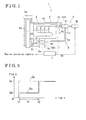
- Fig. 1 is a schematic view of a cooling system for an engine according to a first embodiment disclosed here;
- Fig. 2 is an explanatory graph of a first controlling method for increasing a circulation flow of coolant for a predetermined period of time by an engine control ECU according to the first embodiment
- Fig. 3 shows a flow for a cooling control when warming-up the engine by the engine control ECU according to the first embodiment
- Fig. 4 is an explanatory graph showing effects when the circulation flow of the coolant is increased for the predetermined period of time by the engine control ECU as shown in Fig. 2 ;
- Fig. 5 is an explanatory graph of a second controlling method for increasing a circulation flow of coolant proportionally to an elapsed time by the engine control ECU according to the first embodiment
- Fig. 6 is an explanatory graph of a third controlling method for increasing a circulation flow of coolant in accordance with characteristics of a first order lag filter by the engine control ECU according to the first embodiment;
- Fig. 7 shows a flow for a cooling control when warming-up the engine by the engine control ECU according to a second embodiment
- Fig. 8 is an explanatory graph showing effects when obtaining a modified water temperature by applying a filtering processing to the temperature of the coolant.
- a cooling system 1 is configured to cool an engine mounted to a vehicle and to heat a vehicle compartment using a heat of a coolant.
- the cooling system 1 includes a water jacket 2, a coolant temperature sensitive sensor portion 3, a heater 4, an electric water pump 5, a circulation water path 6, an engine control ECU 7, a radiation water path 81, a radiator 82, and a thermostat valve 83.
- the water jacket 2 serves as a cooling portion of the engine.
- the water jacket 2 is formed surrounding a cylinder of the engine and a coolant flows inside the water jacket 2.
- the coolant sensitive sensor portion 3, which detects a temperature T of the coolant, is positioned at an outlet port 21 of the water jacket 2.
- the heater 4 serves as a heat exchanging device.
- the heater 4 includes a heater core (i.e., serving as a heat exchanging body) 41 which takes in the heat of the coolant and a control unit 42 controlling an operation of the heater core 41.
- the electric power pump 5 serves as a circulation flow varying device which varies circulation flow Qc by controlling an input electric power.
- a vane pump, or a centrifugal pump, or the like, may be applied as the electric water pump 5.
- An outlet port 51 of the electric water pump 5 is connected to an inlet port 22 of the water jacket 2.
- the circulation water path 6 is configured to allow the coolant to circulate through the water jacket 2, the coolant sensitive sensor portion 3, the heater core 41 of the heater 4, and the electric water pump 5.
- a flowing direction of the coolant is indicated with an arrow F in Fig. 1 .
- the circulation water path 6 includes a first path 61 which connects the coolant sensitive sensor portion 3 and an inlet port 411 of the heater core 41 and a second path 62 which connects an outlet port 412 of the heater core 41 and a confluence portion 63.
- a heat radiation path 81 joins the circulation water path 6 at the confluence portion 63.
- the confluence portion 63 is connected to an inlet port 52 of the electric water pump 5.
- the heat radiation path 81 branches from the first path 61 of the circulation path 6 and is connected to the thermostat valve 83 via the radiator 82.
- the heater core 41 of the heater 4 and the radiator 82 are arranged in parallel to each other with respect to the electric water pump 5.
- the radiator 82 includes an internal path through which the coolant passes to radiate the heat.
- the thermostat valve 83 is configured to automatically adjusting an opening degree thereof in accordance with the temperature of the coolant.
- An outlet port 831 whose opening degree is variable of the thermostat valve 83 opens to the confluence portion 63.
- a temperature sensitive portion of the thermostat valve 83 is positioned within the confluence portion 63.
- the thermostat valve 83 is configured to be closed at a low water temperature during the warming-up of the engine.
- the thermostat valve 83 is configured to automatically open when the water temperature rises in response to the operation of the engine thus to flow the coolant to the heat radiation path 81. Accordingly, the heat is radiated by the radiator 82. Further, a reservoir tank 84 which is connected to the heat radiation path 81 and the radiator 82 is provided to absorb changes in a level of the coolant in response to changes in temperature and to compensate for a shortage of the coolant.
- the engine control ECU 7 is an electronic control unit for controlling an operation of the engine and serves as a controller for adjusting/regulating the circulation flow Qc of the coolant.
- the engine control ECU 7 is configured to receive information of the temperature T of the coolant from the coolant temperature sensitive sensor portion 3 and to receive information of a requested flow Qr necessary for heating the vehicle compartment from the control unit 42 of the heater 4. Further, the engine control ECU 7 controls the input electric power supplied to the electric water pump 5 to regulate the circulation flow Qc.
- the engine control ECU 7 controls the operation of the engine based on operational conditions of the engine in accordance with the temperature T. Control amounts controlled by the engine control ECU 7 includes the engine rotation speed, the fuel injection amount, and the ignition timing.
- the foregoing warming-up operation is defined as a warming-up without coolant circulation.
- the engine control ECU 7 circulates the coolant by controlling the electric water pump 5 to continue the warming-up operation so that an entire system including the circulation path 6 is warmed-up.
- the foregoing warming-up operation is defined as a warming-up with coolant.
- the engine control ECU 7 includes a timer for timing an elapsed time tx from a request time t1 at which the requested flow Qr is requested.
- a horizontal axis indicates a time t
- a vertical axis indicates a flow Q
- a dotted line indicates the requested flow Qr
- a solid line indicates the circulation flow Qc.
- the engine control ECU 7 does not increase the circulation flow Qc to the requested flow Qr immediately at the request time t1 and increases the circulation flow Qc to a reduced flow Qd which is less than the requested flow Qr.
- the circulation flow Qc is increased from the reduced flow Qd to the requested flow Qr at a time t2 at which the elapsed time tx reaches a predetermined period of time tr.
- the engine control ECU 7 increases the circulation flow Qc stepwise as a transitional transaction when increasing the circulation flow Qc to the requested flow Qr.
- the requested flow Qr is equal to or less than a predetermined flow Q0
- the reduced flow Qd, the predetermined period of time tr, and the predetermined flow QO may be defined as fixed amounts, however, preferably, may be defined to be variable in accordance with the temperature T and the requested flow Qr at the timing.
- the reduced flow Qd may be reduced, the predetermined period of time tr is elongated, and the predetermined flow Q0 may be determined to be greater.
- the foregoing settings do not meet the request from the heater 4 and a start of the heater 4 is delayed.
- the appropriate reduced flow Qd, the predetermined period of time tr, and the predetermined flow Q0 which enable to start the heater 4 swiftly while restricting the fluctuation of the temperature T to be equal to or less than a predetermined level are determined so as not to influence the control of the warming-up of the engine.
- Those appropriate values may be obtained by experiments performed by changing various conditions, and may further be memorized as a map in the engine control ECU 7.
- Step S1 when the warming-up of the engine is started at Step S1, whether the control ECU 7 operates the warming-up without coolant circulation or the warming-up with coolant circulation is judged at Step S2.
- Step S8 When the warming-up with coolant circulation is operated, whether the requested flow Qr is requested from the heater 4 is judged at Step S3.
- Step S7 When the requested flow Qr is not requested, the transaction advances to Step S7.
- Step S4 is started and the transaction advances to Step S4 after start timing the elapsed time tx.
- the transaction also advances to Step S4.
- step S4 whether the requested flow Qr exceeds the predetermined flow Q0 is judged at step S4.
- the transaction advances to step S7.
- step S5 whether the elapsed time tx timed by the timer is equal to or greater than the predetermined period of time tr is judged at Step S5.
- the transaction advances to step S8, and the transaction advances to step S6 when the elapsed time tx is less than the predetermined period of time tr. Accordingly, the transaction reaches one of Steps S6 to S8 eventually.
- Step S8 Under the conditions that the warming-up with coolant circulation is operated or when the requested flow Qr exceeds the predetermined flow Q0 and the elapsed time tx is equal to or greater than the predetermined period of time tr, the transaction reaches Step S8.
- the condition that the requested flow Qr exceeds the predetermined flow Q0 and the elapsed time tx is equal to or greater than the predetermined period of time tr corresponds to a situation after the transitional transaction with the reduced flow Qd for the predetermined period of time tr is completed.
- the engine control ECU 7 performs a control for a normal warming-up with coolant circulation. In other words, the engine control ECU 7 controls the circulation flow Qc to immediately respond to changes in the requested flow Qr.
- One cycle of the control is completed at one of Steps S6 to S8, and the transaction returns to Step S2 to repeat the transactions of the control.
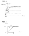
- FIG. 4 Effects when the circulation flow Qc is increased for the predetermined period of time based on Fig. 2 are shown in Fig. 4 .
- the horizontal axis in Fig. 4 indicates time t and the vertical axis in Fig. 4 indicates the temperature T of the coolant detected by the coolant sensitive sensor portion 3.
- Fig. 4 shows an example in which the warming-up of the engine starts at a warm-up starting time t0 and a request of the requested flow Qr is received at a request time t1.
- a solid line i.e., hereinafter referred to as line 1 in Fig.
- FIG. 4 shows changes of the temperature T of the coolant when the circulation flow Qc is increased stepwise to the requested flow Qr via the reduced flow Qd from a state of the warming-up without coolant circulation based on Fig. 2 .
- a dotted line i.e., hereinafter referred to as line 2) in Fig. 4 shows changes of the temperature T of the coolant when a known control method for immediately increasing the circulation flow Qc to the requested flow Qr at the request time t1 in the state of warming-up without coolant circulation.
- a double chain dotted line i.e., hereinafter referred to as line 3 in Fig. 4 shows changes of the temperature of the coolant when a known control method for circulating the coolant is applied from the warm-up starting time t0.
- the engine control ECU 7 increases the circulation flow Qc to the reduced flow Qd immediately after the request time t1.
- the coolant positioned at the second path 62 outside the engine at the start of the operation of the engine reaches the coolant sensitive sensor portion 3 after being warmed up by slowly passing through the water jacket 2.
- the fluctuation of the temperature T of the line 1 is assumed to be smaller than the fluctuation at the line 2, stable conditions for the warming-up can be determined, which does not influence the engine.
- the reduced flow Qd for increasing the circulation flow Qc stepwise for the predetermined period of time tr includes one step.
- the circulation flow Qc may be increased stepwise with plural steps.
- other methods may also be applied.
- Figs. 5 and 6 show examples of alternative methods for increasing the circulation flow Qc for the predetermined period of time tr.
- the circulation flow Qc may be increased proportionally to the elapsed time tx by the engine control ECU 7.
- the engine control ECU 7 controls the electric water pump 5 to increase the circulation flow Qc immediately after the request time t1 with a constant inclination so as to reach the requested flow Qr at time t3 after elapsing the predetermined period of time tr.
- Fig. 6 shows another control method for increasing the circulation flow Qc in accordance with characteristics of a first order lag filter by the engine control ECU 7.
- the engine control ECU 7 controls the electric water pump 5 to increase the circulation flow Qc with certain increment amounts when starting to follow the characteristics of the first order lag filter immediately after the request time t1 and to gradually reduce the increment amount to approximate the requested flow Qr.
- the circulation flow Qc and the requested flow Qr do not come to be equal to each other.
- a time during which the circulation flow Qc and the requested flow Qr are assumed to be substantially the same values in other words, a time during which the circulation flow Qc reaches a value within a range by which stable conditions for the warming-up are attained may be defined as the predetermined time.
- a second embodiment for the cooling system for the engine will be explained with reference to Fig. 7 .
- a feedback control is applied for controlling the circulation flow Qc of the coolant.
- Constructions of the cooling system according to the second embodiment are the same to the cooling system 1 according to the first embodiment shown in Fig. 1 .
- a difference of the second embodiment from the first embodiment is a control method of the engine control ECU 7, that is, software. The constructions common to the first embodiment will not be repeated and only the differences of the second embodiment from the first embodiment will be explained hereinafter.
- the engine control ECU 7 compares the requested flow Qr of the heater 4 to the circulation flow Qc at the time at Step S12.
- the transaction advances to Step S17 to control the electric water pump 5 to maintain the circulation flow Qc.
- the transaction advances to Step S13 to compare a fluctuation ⁇ T of the temperature T of the coolant detected by the coolant sensitive sensor portion 3 to an allowable upper limit value ⁇ TU.
- the fluctuation ⁇ T is assumed to be excessive exceeding the allowable upper limit value ⁇ TU, the transaction advances to Step S15 to control the electric water pump 5 to reduce the circulation flow Qc. Accordingly, the fluctuation ⁇ T of the temperature T is restrained.
- Step S13 When the fluctuation ⁇ T is equal to or less than the allowable upper limit value ⁇ TU at Step S13, the transaction advances to Step S14 to compare the fluctuation ⁇ T of the temperature T to an allowable lower limit value ⁇ TL which is smaller than the allowable upper limit value ⁇ TU (i.e., ⁇ TL ⁇ ⁇ TU).
- Step S16 When the fluctuation ⁇ T is assumed to be excessively small to be less than the allowable lower limit value ⁇ TL, the transaction advances to Step S16 to control the electric water pump 5 to increase the circulation flow Qc. Accordingly, the cooling system 1 is responsive to the request from the heater 4 quickly.
- Step S17 when the fluctuation ⁇ T is equal to or higher than the allowable upper limit value ⁇ TU, the transaction advances to Step S17 because the fluctuation ⁇ T of the temperature T is appropriately maintained to control the electric water pump 5 to maintain the circulation flow Qc. Because one cycle of the control is completed by one of Steps S15 to S17, the transaction returns to Step S12 to repeat the transactions of the control.
- the fluctuation ⁇ T of the temperature T of the coolant is securely controlled to be within the range between the allowable upper limit value ⁇ TU and the allowable lower limit value ⁇ TL, which do not influence the control of the warming-up of the engine.
- the cooling system 1 is responsive to the request from the heater 4 by swiftly increasing the circulation flow Qc within an allowable range.
- a third embodiment of the cooling system for the engine will be explained with reference to Fig. 8 as follows.
- the temperature T to be detected is modified.
- Constructions of the cooling system according to the third embodiment are the same as the cooling system 1 according to the first embodiment shown in Fig. 1 .
- a difference of the third embodiment compared to the first and second embodiments is a control method of the engine control ECU 7, that is, software. The constructions common to the first embodiment will not be repeated and only the differences of the third embodiment from the first and second embodiments will be explained hereinafter.
- the engine control ECU 7 controls the electric water pump 5 to increase the circulation flow Qc to the requested flow Qr immediately when receiving the request of the requested flow Qr from the heater 4 during the warming-up without coolant circulation. Thereafter, the temperature T of the coolant detected by the coolant sensitive sensor portion 3 is filtered to determine conditions for warming-up the engine in accordance with a gradually changing amended coolant temperature TA of the coolant which is obtained by the filtering.
- FIG. 8 Effects of obtaining the amended temperature TA of the coolant by filtering the temperature T of the coolant according to the third embodiment are shown in Fig. 8 .
- Horizontal axes in Fig. 8 indicate time t.
- An upper portion of the graph in Fig. 8 shows changes in the circulation flow Qc, and a lower portion of the graph in Fig. 8 shows changes in the temperature T of the coolant and the amended temperature TA of the coolant.
- the request of the requested flow Qr is received at a request time t1, and the requested flow Qr returns to zero (0) at time t4.
- the engine control ECU 7 controls the electric water pump 5 so that the circulation flow Qc immediately follows the requested flow Qr in response to the changes in the requested flow Qr.
- the engine control ECU 7 obtains the amended temperature TA of the coolant (i.e., indicated with a dotted line) by filtering the detected temperature T (i.e., indicated with a solid line).
- the engine control ECU 7 determines conditions for the warming-up in accordance with the amended temperature TA of the coolant which gradually changes after the request time t1.
- the control of the warming-up is not influenced. Further, by immediately increasing the circulation flow Qc to the requested flow Qr at the request time t1, the cooling system 1 is responsive to the request from the heater 4.
- the electric water pump 5 is applied to the embodiments of the cooling system 1.
- a mechanical water pump or a flow regulating valve, or the like may also be applied.
- an electrically controllable needle valve may be applied as the flow regulating valve to be controlled by the engine control ECU 7.
- the circulation flow Qc can be regulated as desired within a range of an output amount of the mechanical water pump which is defined depending on a rotation speed of the engine.
- a bypass water path which allows the coolant to return immediately from the outlet port 21 of the water jacket 2 to the confluence portion 63, may be provided to enhance the efficiency of the warming-up of the engine.
- the constructions of the embodiments are applicable to other structures.
- the heater 4 serving as the heat exchanging device is provided.
- a defroster may be applied as the heat exchanging device instead of the heater and the defroster may be applied as a defroster 4 in Fig. 1 .
Landscapes
- Engineering & Computer Science (AREA)
- Chemical & Material Sciences (AREA)
- Combustion & Propulsion (AREA)
- Mechanical Engineering (AREA)
- General Engineering & Computer Science (AREA)
- Combined Controls Of Internal Combustion Engines (AREA)
- Control Of Temperature (AREA)
- Air-Conditioning For Vehicles (AREA)
Abstract
Description
- This disclosure relates to a cooling system for cooling an engine by circulating a coolant. More particularly, the disclosure pertains to a cooling system for an engine which includes a heat exchanging device which uses the heat of a coolant.
- Known water-cooling type cooling systems for cooling an engine by compulsorily circulating a coolant are widely in application. A mechanical water pump which is actuated by a crankshaft of the engine, or an electric water pump which is actuated by an electric power supplied from a vehicle mounted battery is generally applied to circulate the coolant.
JPH08-14043A - According to a water pump control apparatus for an internal combustion disclosed in
Patent reference 1, an electric motor is applied to a water pump for circulating a coolant, and the electric motor is controlled by a control means in accordance with the temperature of the coolant detected by a temperature sensor positioned in the vicinity of an outlet port for the coolant. According to the disclosure ofPatent reference 1, an operation of the water pump is stopped when the temperature of the coolant is equal to or lower than a lower limit temperature required for a normal start of the engine. When the temperature of the coolant is higher than the lower limit temperature for the normal start of the engine and equal to or lower than a higher limit temperature for accelerating warming-up, the water pump is rotated at high speeds. Thus, a cranking time for a starter and a time for a self operation of the engine are shortened by stopping the operation of the water pump and a smooth engine operation is performed by swiftly warming-up the entire engine by rotating the water pump at high speeds. -
JP2008-303775A Patent reference 2 discloses that a response of the detection that the coolant boils based on the water level is faster than a response of the detection that the coolant boils based on the temperature. Particularly, it is disclosed that the detection based on the water level is notably more responsive than the detection based on the temperature when the water pump is stopped during the warming-up of the engine, or the like. Further, it is disclosed that the boiling state of the coolant can be detected promptly to increase a flow of the coolant thus to decline the water temperature when the water pump is stopped. Namely, reliability when performing a warm-up of the engine while stopping the water pump is enhanced according to the disclosure ofPatent reference 2. - On the other hand, generally, a heat of the coolant is applied for defrosting or heating the vehicle, which is favorable in terms of energy efficiency. For example, the construction disclosed in
Patent reference 1 includes an air conditioner for heating besides a radiator for radiating the heat of the coolant. The air conditioner for heating uses a part of the coolant as a heat source. - In a case where a heat exchanging means requests a circulation flow during a warming-up of the engine without circulating the coolant in a known cooling system which includes the heat exchanging means such as the air conditioner for heating, a trouble may be caused if the coolant is circulated in response to the request of the heat exchanging means. Conditions for the warming-up when warming-up the engine, for example, idle speed, fuel injection amount, an ignition timing, or the like, are determined in accordance with the temperature of the coolant to be controlled. In those circumstances, the temperature of the coolant is generally detected at a point of a coolant temperature sensitive sensor portion positioned at an outlet port of an engine cooling portion, and a high temperature coolant in the engine flows to the sensor portion first after starting a circulation and next a lower temperature coolant outside the engine flows to the sensor portion. Thus, a fluctuation of the detected water temperature is increased so that the conditions for the warming-up when warming-up the engine are assumed to be unstable and a control for the warming-up is assumed to be difficult. Particularly, when the requested flow is suddenly circulated in a state where the warming-up is proceeded to some extent, the detected water temperature is largely fluctuated, which may influence the engine. As a countermeasure against the foregoing drawback, the fluctuation of the water temperature may be reduced if the warming-up is performed while circulating the coolant. However, the efficiency of the warming-up is declined by a degree that the heat is radiated from the coolant by the circulation of the coolant.
- A need thus exists for a cooling system for an engine which stably controls a warming-up of the engine even if a coolant is circulated when a circulation flow of the coolant is requested from a heat exchanging device when the warming-up of the engine is performed without circulating the coolant and which does not influence the engine.
- In light of the foregoing, the disclosure provides a cooling system for an engine, which includes a cooling portion formed at the engine for flowing a coolant therethrough, a coolant sensitive sensor portion detecting a temperature of the coolant, a heat exchanging device using a heat of the coolant, a circulation flow varying device for varying a circulation flow of the coolant, a circulation path for flowing the coolant therethrough via the cooling portion, the coolant sensitive sensor portion, the heat exchanging device, and the circulation flow varying device, and a controller for regulating the circulation flow of the coolant by controlling the circulation flow varying device while referring to the temperature of the coolant upon a receipt of a request for a requested flow from the heat exchanging device. The controller determines a condition for warming-up the engine when the warming-up of the engine is performed in accordance with the temperature of the coolant, controls the circulation flow varying device for warming-up the engine without circulating the coolant, and increases the circulation flow to the requested flow for a predetermined period of time in a case where the requested flow is requested during the warming-up operation of the engine.
- According to the disclosure, the cooling system for the engine includes cooling portion of the engine, the coolant sensitive sensor portion, the heat exchanging device, the circulation flow varying device, the circulation path, and the controller. The controller determines the condition for warming-up the engine when warming-up the engine in accordance with the temperature of the coolant, warms-up the engine without circulating the coolant by controlling the circulation flow varying device, and increases the circulation flow to the requested flow for the predetermined period of time when receiving a request of the requested flow from the heat exchanging device during the warming-up of the engine. Namely, the circulation flow of the coolant less than the requested flow starts to flow after receiving the request. Thus, the coolant positioned outside the engine which is not warmed by the warming-up of the engine slowly passes through cooling portion of the engine and reaches the coolant sensitive sensor portion after being warmed-up. To the contrary, according to known apparatuses which control the circulation flow to be the requested flow immediately, the coolant positioned outside the engine passes through cooling portion of the engine at a speed that is too fast to warm up the coolant sufficiently. Accordingly, with the construction of the disclosure, a difference between the temperature of the coolant warmed up in the engine from the start of the warming-up of the engine and the temperature of the coolant initially portioned outside the engine and warmed up after passing through cooling portion of the engine is assumed to be smaller compared to the known apparatuses. Further, according to the construction of the disclosure, the fluctuation of the water temperature detected at the coolant sensitive sensor portion is assumed to be smaller, the control of the warming-up operation of the engine is assumed to be stable, which does not influence the engine.
- According to another aspect of the disclosure, the controller increases the circulation flow stepwise. According to still another aspect of the disclosure, the controller increases the circulation flow proportionally to an elapsed time. According to further aspect of the disclosure, the controller increases the circulation flow in accordance with a characteristic of a first order lag filter.
- According to the disclosure, the controller increases the circulation flow stepwise. According to the disclosure, the controller increases the circulation flow proportionally to the elapsed time. Further, according to the disclosure, the controller increases the circulation flow in accordance with the characteristic of the first order lag filter. According to the foregoing constructions of the disclosure, the circulation flow of the coolant less than the requested flow is started to flow after receiving the request of the requested flow from the heat exchanging device, and the circulation flow of the coolant is increased to the requested flow amount for the predetermined period of time. Thus, according to the foregoing constructions of the disclosure, the coolant positioned outside the engine, which is not warmed by the warming-up of the engine slowly, passes through cooling portion of the engine and reaches the coolant sensitive sensor portion after being warmed-up. A difference between the temperature of the coolant warmed up in the engine and the temperature of the coolant initially positioned outside the engine and warmed up after passing through cooling portion of the engine is assumed to be smaller compared to the known apparatuses. Further, according to the construction of the disclosure, the fluctuation of the water temperature detected at the coolant sensitive sensor portion is assumed to be smaller, the control of the warming-up operation of the engine is assumed to be stable, which does not influence the engine.
- According to further aspect of the disclosure, the controller regulates the circulation flow with a feedback control to limit a fluctuation of the temperature of the coolant.
- According to the disclosure, the controller regulates the circulation flow by a feedback control to restrict the fluctuation of the temperature of the coolant. This enables to securely restrict the fluctuation of the temperature of the coolant within a range which does not influence the control of the warming-up of the engine and to respond to the request from the heat exchanging device by swiftly increasing the circulation flow within the range which does not influence the control of the warming-up of the engine.
- According to further aspect of the disclosure, the controller determines the condition for warming-up the engine in accordance with an amended temperature of the coolant which is obtained by filtering the temperature of the coolant after increasing the circulation flow to the requested flow.
- According to the disclosure, the cooling system for the engine includes the cooling portion of the engine, the coolant sensitive sensor portion, the heat exchanging device, the circulation flow varying device, the circulation path, and the controller. The controller determines the condition for warming-up the engine when warming-up the engine in accordance with the temperature of the coolant, warms-up the engine without circulating the coolant by controlling the circulation flow varying device, and increases the circulation flow to the requested flow immediately when receiving a request of the requested flow from the heat exchanging device during the warming-up of the engine, and determines the condition for warming-up in accordance with the modified temperature of the coolant which changes gradually compared to the actually detected temperature of the coolant by applying the filtering processing to the temperature of the coolant thereafter. Namely, because the condition for the warming-up operation of the engine is determined in accordance with the modified temperature of the coolant which changes more gradually compared to the actually detected temperature of the coolant after staring the circulation of the coolant, the control of the warming-up is not influenced. Further, by immediately increasing the circulation flow to the requested flow, the cooling system for the engine respond to the request from the heat exchanging device.
- According to another aspect of the disclosure, a cooling system for an engine includes a cooling portion formed at the engine for flowing a coolant therethrough, a coolant sensitive sensor portion detecting a temperature of the coolant, a heat exchanging device using a heat of the coolant, a circulation flow varying device for varying a circulation flow of the coolant, a circulation path for flowing the coolant therethrough via the cooling portion, the coolant sensitive sensor portion, the heat exchanging device, and the circulation flow varying device, and a controller for regulating the circulation flow of the coolant by controlling the circulation flow varying device while referring to the temperature of the coolant upon a receipt of a request for a requested flow from the heat exchanging device. The controller determines a condition for warming-up the engine when the warming-up of the engine is performed in accordance with the temperature of the coolant, controls the circulation flow varying device for warming-up the engine without circulating the coolant, and increases the circulation flow to the requested flow immediately in a case where the requested flow is requested during the warming-up operation of the engine, and determines the condition for the warming-up of the engine in accordance with an amended temperature of the coolant which is obtained by filtering the temperature of the coolant and changes gradually thereafter.
- According to further aspect of the disclosure, the circulation flow varying device corresponds to an electric water pump which varies a flow amount, a mechanical water pump actuated by the engine, or a flow regulating valve.
- According to the disclosure, the electric water pump which can change the flow amount, the mechanical water pump actuated by the engine, or the flow regulating valve may be applied as the circulation flow varying device. According to the disclosure, the construction of the cooling system for the engine is not limited to the structures and variations of the water pump and is applicable to a wide range.
- According to the disclosure, the cooling system for the engine includes a heat radiation path being branched from the circulation path between the coolant sensitive sensor portion and the heat exchanging device and joining the circulation path at a suction port of the electric water pump, a radiator provided within the heat radiation path, and a thermostat valve. The circulation flow varying device corresponds to an electric water pump which varies a flow amount, the coolant sensitive sensor portion is positioned at an outlet port of the cooling portion of the engine, and an outlet port of the electric water pump is positioned at an inlet port of the cooling portion.
- According to the disclosure, the electric water pump which varies the flow amount is applied as the circulation flow varying device. Further, the cooling system includes the heat radiation path which branches from the circulation path and joins the circulation path after passing through the radiator and the thermostat valve. The thermostat valve automatically adjusts an opening degree thereof in accordance with the temperature of the coolant, the flow of the coolant in the heat radiation path increases as the temperature of the coolant increases to increase the heat radiation from the radiator. Accordingly, the heat of the coolant is preferentially radiated at the heat exchanging device, and the excessive heat which is not radiated at the heat exchanging device is radiated at the radiator. The constructions of the cooling system according to the disclosure may be varied with the construction which radiates the heat only with the heat exchanging device, the construction in which the heat is preferentially radiated at the heat exchanging device and the excessive heat which is not radiated at the heat exchanging device is radiated at the radiator, and the construction which radiates the heat by both of the heat exchanging device and the radiator.
- According to another aspect of the disclosure, the engine is mounted to a vehicle and the heat exchanging device corresponds to either a heater or a defroster.
- According to the disclosure, the engine is mounted to the vehicle, and the heater or the defroster is applied as the heat exchanging device. The cooling system of the disclosure is applicable to the cooling system which is configured to cool the engine mounted to the vehicle.
- The foregoing and additional features and characteristics of this disclosure will become more apparent from the following detailed description considered with the reference to the accompanying drawings, wherein:
-
Fig. 1 is a schematic view of a cooling system for an engine according to a first embodiment disclosed here; -
Fig. 2 is an explanatory graph of a first controlling method for increasing a circulation flow of coolant for a predetermined period of time by an engine control ECU according to the first embodiment; -
Fig. 3 shows a flow for a cooling control when warming-up the engine by the engine control ECU according to the first embodiment; -
Fig. 4 is an explanatory graph showing effects when the circulation flow of the coolant is increased for the predetermined period of time by the engine control ECU as shown inFig. 2 ; -
Fig. 5 is an explanatory graph of a second controlling method for increasing a circulation flow of coolant proportionally to an elapsed time by the engine control ECU according to the first embodiment; -
Fig. 6 is an explanatory graph of a third controlling method for increasing a circulation flow of coolant in accordance with characteristics of a first order lag filter by the engine control ECU according to the first embodiment; -
Fig. 7 shows a flow for a cooling control when warming-up the engine by the engine control ECU according to a second embodiment; and -
Fig. 8 is an explanatory graph showing effects when obtaining a modified water temperature by applying a filtering processing to the temperature of the coolant. - Embodiments of a cooling system for an engine will be explained with reference to illustrations of drawing figures as follows.
- A first embodiment of the cooling system for the engine will be explained with reference to
Figs. 1 to 6 . As illustrated inFig. 1 , acooling system 1 is configured to cool an engine mounted to a vehicle and to heat a vehicle compartment using a heat of a coolant. Thecooling system 1 includes awater jacket 2, a coolant temperaturesensitive sensor portion 3, aheater 4, anelectric water pump 5, acirculation water path 6, anengine control ECU 7, aradiation water path 81, aradiator 82, and athermostat valve 83. - The
water jacket 2 serves as a cooling portion of the engine. Thewater jacket 2 is formed surrounding a cylinder of the engine and a coolant flows inside thewater jacket 2. The coolantsensitive sensor portion 3, which detects a temperature T of the coolant, is positioned at anoutlet port 21 of thewater jacket 2. Theheater 4 serves as a heat exchanging device. Theheater 4 includes a heater core (i.e., serving as a heat exchanging body) 41 which takes in the heat of the coolant and acontrol unit 42 controlling an operation of theheater core 41. Theelectric power pump 5 serves as a circulation flow varying device which varies circulation flow Qc by controlling an input electric power. A vane pump, or a centrifugal pump, or the like, may be applied as theelectric water pump 5. An outlet port 51 of theelectric water pump 5 is connected to aninlet port 22 of thewater jacket 2. - The
circulation water path 6 is configured to allow the coolant to circulate through thewater jacket 2, the coolantsensitive sensor portion 3, theheater core 41 of theheater 4, and theelectric water pump 5. A flowing direction of the coolant is indicated with an arrow F inFig. 1 . Thecirculation water path 6 includes afirst path 61 which connects the coolantsensitive sensor portion 3 and aninlet port 411 of theheater core 41 and asecond path 62 which connects anoutlet port 412 of theheater core 41 and aconfluence portion 63. Aheat radiation path 81 joins thecirculation water path 6 at theconfluence portion 63. Theconfluence portion 63 is connected to aninlet port 52 of theelectric water pump 5. - The
heat radiation path 81 branches from thefirst path 61 of thecirculation path 6 and is connected to thethermostat valve 83 via theradiator 82. Theheater core 41 of theheater 4 and theradiator 82 are arranged in parallel to each other with respect to theelectric water pump 5. Theradiator 82 includes an internal path through which the coolant passes to radiate the heat. Thethermostat valve 83 is configured to automatically adjusting an opening degree thereof in accordance with the temperature of the coolant. Anoutlet port 831 whose opening degree is variable of thethermostat valve 83 opens to theconfluence portion 63. A temperature sensitive portion of thethermostat valve 83 is positioned within theconfluence portion 63. Thethermostat valve 83 is configured to be closed at a low water temperature during the warming-up of the engine. Thethermostat valve 83 is configured to automatically open when the water temperature rises in response to the operation of the engine thus to flow the coolant to theheat radiation path 81. Accordingly, the heat is radiated by theradiator 82. Further, areservoir tank 84 which is connected to theheat radiation path 81 and theradiator 82 is provided to absorb changes in a level of the coolant in response to changes in temperature and to compensate for a shortage of the coolant. - The
engine control ECU 7 is an electronic control unit for controlling an operation of the engine and serves as a controller for adjusting/regulating the circulation flow Qc of the coolant. Theengine control ECU 7 is configured to receive information of the temperature T of the coolant from the coolant temperaturesensitive sensor portion 3 and to receive information of a requested flow Qr necessary for heating the vehicle compartment from thecontrol unit 42 of theheater 4. Further, theengine control ECU 7 controls the input electric power supplied to theelectric water pump 5 to regulate the circulation flow Qc. Theengine control ECU 7 controls the operation of the engine based on operational conditions of the engine in accordance with the temperature T. Control amounts controlled by theengine control ECU 7 includes the engine rotation speed, the fuel injection amount, and the ignition timing. - Further, the
engine control ECU 7 determining the conditions for warming-up the engine in accordance with the temperature T and warms-up the engine without circulating the coolant by controlling theelectric water pump 5. That is, theengine control ECU 7 warms-up the engine when determining that the circulation flow Qc is equal to zero (Qc = 0). The foregoing warming-up operation is defined as a warming-up without coolant circulation. On the other hand, when the temperature T reaches a predetermined value (level), theengine control ECU 7 circulates the coolant by controlling theelectric water pump 5 to continue the warming-up operation so that an entire system including thecirculation path 6 is warmed-up. The foregoing warming-up operation is defined as a warming-up with coolant. Theengine control ECU 7 controls theelectric water pump 5 to increment the circulation flow Qc to the requested flow Qr for a predetermined period of time when receiving a request for the requested flow Qr from thecontrol unit 42 of theheater 4 during the warming-up without coolant circulation at which the circulation flow Qc is equal to zero (Qc = 0). Theengine control ECU 7 includes a timer for timing an elapsed time tx from a request time t1 at which the requested flow Qr is requested. - Referring to
Fig. 2 , a horizontal axis indicates a time t, a vertical axis indicates a flow Q, a dotted line indicates the requested flow Qr, and a solid line indicates the circulation flow Qc. The graph inFig. 2 shows a case where the requested flow Qr is requested at the request time t1 during the warming-up without coolant circulation in which the circulation flow Qc is equal to zero (Qc = 0). As shown inFig. 2 , theengine control ECU 7 does not increase the circulation flow Qc to the requested flow Qr immediately at the request time t1 and increases the circulation flow Qc to a reduced flow Qd which is less than the requested flow Qr. Thereafter, the circulation flow Qc is increased from the reduced flow Qd to the requested flow Qr at a time t2 at which the elapsed time tx reaches a predetermined period of time tr. Namely, theengine control ECU 7 increases the circulation flow Qc stepwise as a transitional transaction when increasing the circulation flow Qc to the requested flow Qr. In those circumstances, in a case where the requested flow Qr is equal to or less than a predetermined flow Q0, the warming-up of the engine is continued maintaining the circulation flow Qc to be zero (Qc = 0). - The reduced flow Qd, the predetermined period of time tr, and the predetermined flow QO may be defined as fixed amounts, however, preferably, may be defined to be variable in accordance with the temperature T and the requested flow Qr at the timing. In order to reduce the fluctuation of the temperature T, the reduced flow Qd may be reduced, the predetermined period of time tr is elongated, and the predetermined flow Q0 may be determined to be greater. To the contrary, the foregoing settings do not meet the request from the
heater 4 and a start of theheater 4 is delayed. Thus, according to the construction of the embodiment, the appropriate reduced flow Qd, the predetermined period of time tr, and the predetermined flow Q0 which enable to start theheater 4 swiftly while restricting the fluctuation of the temperature T to be equal to or less than a predetermined level are determined so as not to influence the control of the warming-up of the engine. Those appropriate values may be obtained by experiments performed by changing various conditions, and may further be memorized as a map in theengine control ECU 7. - An operation of the
cooling system 1 for the engine according to the first embodiment will be explained with reference toFig. 3 . As illustrated inFig. 3 , when the warming-up of the engine is started at Step S1, whether thecontrol ECU 7 operates the warming-up without coolant circulation or the warming-up with coolant circulation is judged at Step S2. When the warming-up with coolant circulation is operated, the transaction proceeds to Step S8. When the warming-up without coolant circulation is operated, whether the requested flow Qr is requested from theheater 4 is judged at Step S3. When the requested flow Qr is not requested, the transaction advances to Step S7. When the requested flow Qr is requested for the first time, a timer is started and the transaction advances to Step S4 after start timing the elapsed time tx. When the requested flow Qr continues, the transaction also advances to Step S4. - Next, whether the requested flow Qr exceeds the predetermined flow Q0 is judged at step S4. When the requested flow Qr does not exceed the predetermined flow Q0, the transaction advances to step S7. When the requested flow Qr exceeds the predetermined flow Q0, whether the elapsed time tx timed by the timer is equal to or greater than the predetermined period of time tr is judged at Step S5. In those circumstances, when the elapsed time tx is equal to or greater than the predetermined period of time tr, the transaction advances to step S8, and the transaction advances to step S6 when the elapsed time tx is less than the predetermined period of time tr. Accordingly, the transaction reaches one of Steps S6 to S8 eventually.
- Under the conditions that the requested flow Qr exceeding the predetermined flow Q0 is received during the warming-up without coolant circulation and the elapsed time tx is less than the predetermined period of time tr, the transaction reaches Step S6. In those circumstances, the
engine control ECU 7 controls theelectric water pump 5 to change the circulation flow Qc to the reduced flow Qd. Under the conditions that warming-up without coolant circulation is operated and the requested flow Qr is zero or equal to or less than predetermined flow Q0, the transaction reaches Step S7. In those circumstances, theengine control ECU 7 controls the circulation flow Qc to be zero (Qc =0) and the operation of warming-up without coolant circulation continues. Under the conditions that the warming-up with coolant circulation is operated or when the requested flow Qr exceeds the predetermined flow Q0 and the elapsed time tx is equal to or greater than the predetermined period of time tr, the transaction reaches Step S8. The condition that the requested flow Qr exceeds the predetermined flow Q0 and the elapsed time tx is equal to or greater than the predetermined period of time tr corresponds to a situation after the transitional transaction with the reduced flow Qd for the predetermined period of time tr is completed. In those circumstances, theengine control ECU 7 performs a control for a normal warming-up with coolant circulation. In other words, theengine control ECU 7 controls the circulation flow Qc to immediately respond to changes in the requested flow Qr. - One cycle of the control is completed at one of Steps S6 to S8, and the transaction returns to Step S2 to repeat the transactions of the control.
- Advantages and effects of the
cooling system 1 for the engine according to the first embodiment will be explained with reference toFig. 4 . Effects when the circulation flow Qc is increased for the predetermined period of time based onFig. 2 are shown inFig. 4 . The horizontal axis inFig. 4 indicates time t and the vertical axis inFig. 4 indicates the temperature T of the coolant detected by the coolantsensitive sensor portion 3.Fig. 4 shows an example in which the warming-up of the engine starts at a warm-up starting time t0 and a request of the requested flow Qr is received at a request time t1. A solid line (i.e., hereinafter referred to as line 1) inFig. 4 shows changes of the temperature T of the coolant when the circulation flow Qc is increased stepwise to the requested flow Qr via the reduced flow Qd from a state of the warming-up without coolant circulation based onFig. 2 . A dotted line (i.e., hereinafter referred to as line 2) inFig. 4 shows changes of the temperature T of the coolant when a known control method for immediately increasing the circulation flow Qc to the requested flow Qr at the request time t1 in the state of warming-up without coolant circulation. A double chain dotted line (i.e., hereinafter referred to as line 3) inFig. 4 shows changes of the temperature of the coolant when a known control method for circulating the coolant is applied from the warm-up starting time t0. - First, comparing the
line 1 and theline 2 to theline 3, effects of the warming-up without coolant circulation during which the coolant is not circulated will be explained as follows. Theline 1 and theline 2 at which the warming-up without coolant circulation is performed show that the temperature T surge immediately after the warm-up starting time t0 compared to the known control method for circulating the coolant indicated withline 3 in which the warming-up without coolant circulation is not performed. This indicates that an inside of the engine including a piston is swiftly warmed-up. - Next, comparing the
line 1 and theline 2, effects of increasing the circulation flow Qc stepwise will be explained as follows. Theengine control ECU 7 immediately increases the circulation flow Qc to the requested flow Qr at the request time t1. Consequently, the temperature T rises to P1 inFig. 4 during the coolant, which is warmed-up in thewater jacket 2 of the engine from a start of an operation of the engine, flows, however, the temperature T declines to P2 inFig. 4 after the coolant in thesecond path 62 outside the engine comes to flow the coolantsensitive sensor portion 3, which causes a sharp fluctuation of the temperature. Thus, it becomes difficult for theengine control ECU 7 to determine stable conditions for the warming-up in accordance with the temperature T, the control of the warming-up is assumed to be difficult, which may influence the engine. - On the other hand, as indicated with
line 1 inFig. 4 , theengine control ECU 7 increases the circulation flow Qc to the reduced flow Qd immediately after the request time t1. In consequence, the coolant positioned at thesecond path 62 outside the engine at the start of the operation of the engine reaches the coolantsensitive sensor portion 3 after being warmed up by slowly passing through thewater jacket 2. Accordingly, as illustrated inFig. 4 , the fluctuation of the temperature T of theline 1 is assumed to be smaller than the fluctuation at theline 2, stable conditions for the warming-up can be determined, which does not influence the engine. - According to the first embodiment, the reduced flow Qd for increasing the circulation flow Qc stepwise for the predetermined period of time tr includes one step. However, the circulation flow Qc may be increased stepwise with plural steps. Further, with regard to the method for increasing the circulation flow Qc for the predetermined period of time tr, other methods may also be applied.
Figs. 5 and6 show examples of alternative methods for increasing the circulation flow Qc for the predetermined period of time tr. - As shown in
Fig. 5 , the circulation flow Qc may be increased proportionally to the elapsed time tx by theengine control ECU 7. As illustrated inFig. 5 , theengine control ECU 7 controls theelectric water pump 5 to increase the circulation flow Qc immediately after the request time t1 with a constant inclination so as to reach the requested flow Qr at time t3 after elapsing the predetermined period of time tr. - Further,
Fig. 6 shows another control method for increasing the circulation flow Qc in accordance with characteristics of a first order lag filter by theengine control ECU 7. As shown inFig. 6 , theengine control ECU 7 controls theelectric water pump 5 to increase the circulation flow Qc with certain increment amounts when starting to follow the characteristics of the first order lag filter immediately after the request time t1 and to gradually reduce the increment amount to approximate the requested flow Qr. In a case where the characteristics of the first order lag filter is applied as shown inFig. 6 , the circulation flow Qc and the requested flow Qr do not come to be equal to each other. However, a time during which the circulation flow Qc and the requested flow Qr are assumed to be substantially the same values, in other words, a time during which the circulation flow Qc reaches a value within a range by which stable conditions for the warming-up are attained may be defined as the predetermined time. - Various control methods other than the foregoing examples may be applied for reaching the circulation flow Qc to the requested flow Qr for the predetermined period of time.
- A second embodiment for the cooling system for the engine will be explained with reference to
Fig. 7 . According to the second embodiment, a feedback control is applied for controlling the circulation flow Qc of the coolant. Constructions of the cooling system according to the second embodiment are the same to thecooling system 1 according to the first embodiment shown inFig. 1 . A difference of the second embodiment from the first embodiment is a control method of theengine control ECU 7, that is, software. The constructions common to the first embodiment will not be repeated and only the differences of the second embodiment from the first embodiment will be explained hereinafter. - As illustrated in
Fig. 7 , upon a start of the warming-up at Step S11, theengine control ECU 7 compares the requested flow Qr of theheater 4 to the circulation flow Qc at the time at Step S12. When the requested flow Qr is equal to or less than the circulation flow Qc, because the request of theheater 4 is already satisfied, the transaction advances to Step S17 to control theelectric water pump 5 to maintain the circulation flow Qc. When the requested flow Qr exceeds the circulation flow Qc, the transaction advances to Step S13 to compare a fluctuation ΔT of the temperature T of the coolant detected by the coolantsensitive sensor portion 3 to an allowable upper limit value ΔTU. When the fluctuation ΔT is assumed to be excessive exceeding the allowable upper limit value ΔTU, the transaction advances to Step S15 to control theelectric water pump 5 to reduce the circulation flow Qc. Accordingly, the fluctuation ΔT of the temperature T is restrained. - When the fluctuation ΔT is equal to or less than the allowable upper limit value ΔTU at Step S13, the transaction advances to Step S14 to compare the fluctuation ΔT of the temperature T to an allowable lower limit value ΔTL which is smaller than the allowable upper limit value ΔTU (i.e., ΔTL < ΔTU). When the fluctuation ΔT is assumed to be excessively small to be less than the allowable lower limit value ΔTL, the transaction advances to Step S16 to control the
electric water pump 5 to increase the circulation flow Qc. Accordingly, thecooling system 1 is responsive to the request from theheater 4 quickly. Further, when the fluctuation ΔT is equal to or higher than the allowable upper limit value ΔTU, the transaction advances to Step S17 because the fluctuation ΔT of the temperature T is appropriately maintained to control theelectric water pump 5 to maintain the circulation flow Qc. Because one cycle of the control is completed by one of Steps S15 to S17, the transaction returns to Step S12 to repeat the transactions of the control. - According to the flow for controlling the coolant of the second embodiment, the fluctuation ΔT of the temperature T of the coolant is securely controlled to be within the range between the allowable upper limit value ΔTU and the allowable lower limit value ΔTL, which do not influence the control of the warming-up of the engine. In addition to that, according to the second embodiment, the
cooling system 1 is responsive to the request from theheater 4 by swiftly increasing the circulation flow Qc within an allowable range. - A third embodiment of the cooling system for the engine will be explained with reference to
Fig. 8 as follows. According to the third embodiment, instead of regulating the circulation flow Qc of the coolant, the temperature T to be detected is modified. Constructions of the cooling system according to the third embodiment are the same as thecooling system 1 according to the first embodiment shown inFig. 1 . A difference of the third embodiment compared to the first and second embodiments is a control method of theengine control ECU 7, that is, software. The constructions common to the first embodiment will not be repeated and only the differences of the third embodiment from the first and second embodiments will be explained hereinafter. According to the third embodiment, theengine control ECU 7 controls theelectric water pump 5 to increase the circulation flow Qc to the requested flow Qr immediately when receiving the request of the requested flow Qr from theheater 4 during the warming-up without coolant circulation. Thereafter, the temperature T of the coolant detected by the coolantsensitive sensor portion 3 is filtered to determine conditions for warming-up the engine in accordance with a gradually changing amended coolant temperature TA of the coolant which is obtained by the filtering. - Effects of obtaining the amended temperature TA of the coolant by filtering the temperature T of the coolant according to the third embodiment are shown in
Fig. 8 . Horizontal axes inFig. 8 indicate time t. An upper portion of the graph inFig. 8 shows changes in the circulation flow Qc, and a lower portion of the graph inFig. 8 shows changes in the temperature T of the coolant and the amended temperature TA of the coolant. The request of the requested flow Qr is received at a request time t1, and the requested flow Qr returns to zero (0) at time t4. As shown in the upper portion of the graph, theengine control ECU 7 controls theelectric water pump 5 so that the circulation flow Qc immediately follows the requested flow Qr in response to the changes in the requested flow Qr. Further, as shown in the lower portion of the graph inFig. 8 , theengine control ECU 7 obtains the amended temperature TA of the coolant (i.e., indicated with a dotted line) by filtering the detected temperature T (i.e., indicated with a solid line). Theengine control ECU 7 determines conditions for the warming-up in accordance with the amended temperature TA of the coolant which gradually changes after the request time t1. - Thus, according to the third embodiment, because the conditions for the warming-up is determined in accordance with the amended temperature which changes gradually compared to the actually detected temperature T, the control of the warming-up is not influenced. Further, by immediately increasing the circulation flow Qc to the requested flow Qr at the request time t1, the
cooling system 1 is responsive to the request from theheater 4. - The
electric water pump 5 is applied to the embodiments of thecooling system 1. Instead of theelectric water pump 5, a mechanical water pump or a flow regulating valve, or the like, may also be applied. For example, an electrically controllable needle valve may be applied as the flow regulating valve to be controlled by theengine control ECU 7. According to the foregoing construction, by controlling the opening degree of the needle valve, the circulation flow Qc can be regulated as desired within a range of an output amount of the mechanical water pump which is defined depending on a rotation speed of the engine. - Further, as a modified example of the embodiments, a bypass water path, which allows the coolant to return immediately from the
outlet port 21 of thewater jacket 2 to theconfluence portion 63, may be provided to enhance the efficiency of the warming-up of the engine. The constructions of the embodiments are applicable to other structures. - According to the foregoing embodiments, the
heater 4 serving as the heat exchanging device is provided. However, a defroster may be applied as the heat exchanging device instead of the heater and the defroster may be applied as adefroster 4 inFig. 1 . - It is explicitly stated that all features disclosed in the description and/or the claims are intended to be disclosed separately and independently from each other for the purpose of original disclosure as well as for the purpose of restricting the claimed invention independent of the composition of the features in the embodiments and/or the claims. It is explicitly stated that all value ranges or indications of groups of entities disclose every possible intermediate value or intermediate entity for the purpose of original disclosure as well as for the purpose of restricting the claimed invention, in particular as limits of value ranges.
Claims (10)
- A cooling system (1) for an engine, comprising:a cooling portion (2) formed at the engine for flowing a coolant therethrough;a coolant sensitive sensor portion (3) detecting a temperature of the coolant;a heat exchanging device (4) using a heat of the coolant;a circulation flow varying device (5) for varying a circulation flow of the coolant;a circulation path (6) for flowing the coolant therethrough via the cooling portion, the coolant sensitive sensor portion (3), the heat exchanging device (4), and the circulation flow varying device (5); anda controller (7) for regulating the circulation flow of the coolant by controlling the circulation flow varying device (5) while referring to the temperature of the coolant upon a receipt of a request for a requested flow from the heat exchanging device (4); whereinthe controller (7) determines a condition for warming-up the engine when the warming-up of the engine is performed in accordance with the temperature of the coolant, controls the circulation flow varying device (5) for warming-up the engine without circulating the coolant, and increases the circulation flow to the requested flow for a predetermined period of time in a case where the requested flow is requested during the warming-up operation of the engine.
- The cooling system for the engine according to claim 1, wherein the controller (7) increases the circulation flow stepwise.
- The cooling system for the engine according to claim 1, wherein the controller (7) increases the circulation flow proportionally to an elapsed time.
- The cooling system for the engine according to claim 1, wherein the controller (7) increases the circulation flow in accordance with a characteristic of a first order lag filter.
- The cooling system for the engine according to claim 1, wherein the controller (7) regulates the circulation flow with a feedback control to limit a fluctuation of the temperature of the coolant.
- The cooling system for the engine according to claim 1, wherein the controller (7) determines the condition for warming-up the engine in accordance with an amended temperature of the coolant which is obtained by filtering the temperature of the coolant after increasing the circulation flow to the requested flow.
- A cooling system for an engine, comprising:a cooling portion (2) formed at the engine for flowing a coolant therethrough;a coolant sensitive sensor portion (3) detecting a temperature of the coolant;a heat exchanging device (4) using a heat of the coolant;a circulation flow varying device (5) for varying a circulation flow of the coolant;a circulation path (6) for flowing the coolant therethrough via the cooling portion (2), the coolant sensitive sensor portion (3), the heat exchanging device (4), and the circulation flow varying device (5); anda controller (7) for regulating the circulation flow of the coolant by controlling the circulation flow varying device (5) while referring to the temperature of the coolant upon a receipt of a request for a requested flow from the heat exchanging device (4); whereinthe controller (7) determines a condition for warming-up the engine when the warming-up of the engine is performed in accordance with the temperature of the coolant, controls the circulation flow varying device (5) for warming-up the engine without circulating the coolant, and increases the circulation flow to the requested flow immediately in a case where the requested flow is requested during the warming-up operation of the engine, and determines the condition for the warming-up of the engine in accordance with an amended temperature of the coolant which is obtained by filtering the temperature of the coolant and changes gradually thereafter.
- The cooling system for the engine according to any one of claims 1 to 7, wherein the circulation flow varying device (5) corresponds to an electric water pump which varies a flow amount, a mechanical water pump actuated by the engine, or a flow regulating valve.
- The cooling system for the engine according to any one of claims 1 to 8 further comprising:a heat radiation path (81) being branched from the circulation path (6) between the coolant sensitive sensor portion (3) and the heat exchanging device (4) and joining the circulation path (6) at a suction port of the electric water pump (5);a radiator (82) provided within the heat radiation path (81); anda thermostat valve (83); whereinthe circulation flow varying device (5) corresponds to an electric water pump which varies a flow amount, the coolant sensitive sensor portion (3) is positioned at an outlet port of the cooling portion (2) of the engine, and an outlet port of the electric water pump (5) is positioned at an inlet port of the cooling portion (2).
- The cooling system for the engine according to any one of claims 1 to 9, wherein the engine is mounted to a vehicle and the heat exchanging device (4) corresponds to either a heater or a defroster.
Applications Claiming Priority (1)
| Application Number | Priority Date | Filing Date | Title |
|---|---|---|---|
| JP2009266408A JP4860746B2 (en) | 2009-11-24 | 2009-11-24 | Engine cooling system |
Publications (3)
| Publication Number | Publication Date |
|---|---|
| EP2333268A2 true EP2333268A2 (en) | 2011-06-15 |
| EP2333268A3 EP2333268A3 (en) | 2012-01-04 |
| EP2333268B1 EP2333268B1 (en) | 2013-05-01 |
Family
ID=43736042
Family Applications (1)
| Application Number | Title | Priority Date | Filing Date |
|---|---|---|---|
| EP10191902.5A Not-in-force EP2333268B1 (en) | 2009-11-24 | 2010-11-19 | Cooling system for engine |
Country Status (4)
| Country | Link |
|---|---|
| US (1) | US20110120394A1 (en) |
| EP (1) | EP2333268B1 (en) |
| JP (1) | JP4860746B2 (en) |
| CN (1) | CN102072007A (en) |
Cited By (3)
| Publication number | Priority date | Publication date | Assignee | Title |
|---|---|---|---|---|
| FR3002281A1 (en) * | 2013-02-19 | 2014-08-22 | Peugeot Citroen Automobiles Sa | Cooling circuit for thermal engine of car, has thermostatic valve located in inlet manifold upstream of feed pump, where valve blocks flow of coolant in inlet manifold as long as coolant temperature is below threshold temperature |
| EP3088715A1 (en) * | 2015-04-28 | 2016-11-02 | Toyota Jidosha Kabushiki Kaisha | Control system for internal combustion engine |
| EP3369906A1 (en) * | 2017-03-02 | 2018-09-05 | Toyota Jidosha Kabushiki Kaisha | Coolant circulation system for vehicle-mounted internal combustion engine |
Families Citing this family (21)
| Publication number | Priority date | Publication date | Assignee | Title |
|---|---|---|---|---|
| WO2013003950A1 (en) * | 2011-07-04 | 2013-01-10 | Litens Automotive Partnership | System and method for pumping coolant through an internal combustion engine for a vehicle |
| JP5892469B2 (en) * | 2012-03-09 | 2016-03-23 | スズキ株式会社 | Cooling device for internal combustion engine for vehicle |
| US9562534B2 (en) | 2012-05-04 | 2017-02-07 | Ghsp, Inc. | In-line dual pump and motor with control device |
| US9115720B2 (en) | 2012-05-04 | 2015-08-25 | Ghsp, Inc. | Dual pump and motor with control device |
| US9869232B2 (en) * | 2012-06-27 | 2018-01-16 | Ford Global Technologies, Llc | Variable-speed pump control for engine coolant system with variable restriction |
| US9752590B2 (en) | 2013-03-13 | 2017-09-05 | Ghsp, Inc. | Two pump design with coplanar interface surface |
| US8960134B1 (en) * | 2013-07-31 | 2015-02-24 | GM Global Technology Operations LLC | Targeted cooling with individualized feeding ports to cylinders |
| US11015585B2 (en) | 2014-05-01 | 2021-05-25 | Ghsp, Inc. | Submersible pump assembly |
| US10087927B2 (en) | 2014-05-01 | 2018-10-02 | Ghsp, Inc. | Electric motor with flux collector |
| US9869223B2 (en) * | 2014-08-22 | 2018-01-16 | GM Global Technology Operations LLC | Flexible engine metal warming system and method for an internal combustion engine |
| US9964022B2 (en) * | 2015-03-26 | 2018-05-08 | GM Global Technology Operations LLC | Engine off cooling strategy |
| CN106150824A (en) * | 2015-03-30 | 2016-11-23 | 长城汽车股份有限公司 | The warm-up control method of electromotor and device |
| JP6701715B2 (en) | 2015-12-21 | 2020-05-27 | 株式会社デンソー | Vehicle air conditioner |
| JP6790901B2 (en) * | 2017-02-17 | 2020-11-25 | スズキ株式会社 | Internal combustion engine cooling system |
| CN107271163B (en) * | 2017-06-16 | 2018-09-28 | 英特尔产品(成都)有限公司 | Local diagnosis for cooler and verification system and method |
| US10119454B1 (en) * | 2017-11-13 | 2018-11-06 | GM Global Technology Operations LLC | Flow model inversion using a multi-dimensional search algorithm |
| JP6848828B2 (en) | 2017-11-24 | 2021-03-24 | トヨタ自動車株式会社 | Rotating machine cooling device |
| CN109281747A (en) * | 2018-11-09 | 2019-01-29 | 东风商用车有限公司 | Cooling liquid adapting unit with temperature control device |
| CN112829567B (en) * | 2019-11-25 | 2022-06-17 | 江铃汽车股份有限公司 | Control method for cooling system of electric automobile |
| CN114837792A (en) | 2021-03-10 | 2022-08-02 | 美普盛(上海)汽车零部件有限公司 | Electric coolant pump with expansion compensation sealing element |
| CN113775405A (en) * | 2021-11-11 | 2021-12-10 | 潍坊力创电子科技有限公司 | Engine cooling system capable of adjusting power consumption of water pump and control method of engine cooling system |
Citations (1)
| Publication number | Priority date | Publication date | Assignee | Title |
|---|---|---|---|---|
| JP2008303775A (en) | 2007-06-07 | 2008-12-18 | Nippon Soken Inc | Cooling device for internal combustion engine |
Family Cites Families (15)
| Publication number | Priority date | Publication date | Assignee | Title |
|---|---|---|---|---|
| JPS58124017A (en) * | 1982-01-19 | 1983-07-23 | Nippon Denso Co Ltd | Cooling system controller of engine |
| DE3810174C2 (en) * | 1988-03-25 | 1996-09-19 | Hella Kg Hueck & Co | Device for regulating the coolant temperature of an internal combustion engine, in particular in motor vehicles |
| DE4109498B4 (en) * | 1991-03-22 | 2006-09-14 | Robert Bosch Gmbh | Device and method for controlling the temperature of an internal combustion engine |
| JP3513919B2 (en) * | 1994-06-30 | 2004-03-31 | いすゞ自動車株式会社 | Water pump control device for internal combustion engine |
| DE19508102C1 (en) * | 1995-03-08 | 1996-07-25 | Volkswagen Ag | Method for regulating a cooling circuit of an internal combustion engine, in particular for motor vehicles |
| JP2000303841A (en) * | 1999-04-20 | 2000-10-31 | Honda Motor Co Ltd | Engine cooling control device |
| US6739290B2 (en) * | 2001-03-06 | 2004-05-25 | Calsonic Kansei Corporation | Cooling system for water-cooled internal combustion engine and control method applicable to cooling system therefor |
| DE10154091A1 (en) * | 2001-11-02 | 2003-05-15 | Bayerische Motoren Werke Ag | Method and device for controlling a cooling system of an internal combustion engine |
| US6745726B2 (en) * | 2002-07-29 | 2004-06-08 | Visteon Global Technologies, Inc. | Engine thermal management for internal combustion engine |
| JP3932277B2 (en) * | 2002-10-18 | 2007-06-20 | 日本サーモスタット株式会社 | Control method of electronic control thermostat |
| JP2004316472A (en) * | 2003-04-14 | 2004-11-11 | Nissan Motor Co Ltd | Cooling device for internal combustion engine |
| JP2004360509A (en) * | 2003-06-03 | 2004-12-24 | Nissan Motor Co Ltd | Cooling device for internal combustion engine |
| DE10332947A1 (en) * | 2003-07-19 | 2005-02-03 | Daimlerchrysler Ag | Internal combustion engine for a motor vehicle |
| JP4529709B2 (en) * | 2005-02-01 | 2010-08-25 | マツダ株式会社 | Engine cooling system |
| JP2007016718A (en) * | 2005-07-08 | 2007-01-25 | Toyota Motor Corp | Engine cooling system |
-
2009
- 2009-11-24 JP JP2009266408A patent/JP4860746B2/en not_active Expired - Fee Related
-
2010
- 2010-11-19 EP EP10191902.5A patent/EP2333268B1/en not_active Not-in-force
- 2010-11-23 US US12/952,827 patent/US20110120394A1/en not_active Abandoned
- 2010-11-24 CN CN201010566219XA patent/CN102072007A/en active Pending
Patent Citations (1)
| Publication number | Priority date | Publication date | Assignee | Title |
|---|---|---|---|---|
| JP2008303775A (en) | 2007-06-07 | 2008-12-18 | Nippon Soken Inc | Cooling device for internal combustion engine |
Cited By (4)
| Publication number | Priority date | Publication date | Assignee | Title |
|---|---|---|---|---|
| FR3002281A1 (en) * | 2013-02-19 | 2014-08-22 | Peugeot Citroen Automobiles Sa | Cooling circuit for thermal engine of car, has thermostatic valve located in inlet manifold upstream of feed pump, where valve blocks flow of coolant in inlet manifold as long as coolant temperature is below threshold temperature |
| EP3088715A1 (en) * | 2015-04-28 | 2016-11-02 | Toyota Jidosha Kabushiki Kaisha | Control system for internal combustion engine |
| US10280859B2 (en) | 2015-04-28 | 2019-05-07 | Toyota Jidosha Kabushiki Kaisha | Control system for internal combustion engine |
| EP3369906A1 (en) * | 2017-03-02 | 2018-09-05 | Toyota Jidosha Kabushiki Kaisha | Coolant circulation system for vehicle-mounted internal combustion engine |
Also Published As
| Publication number | Publication date |
|---|---|
| US20110120394A1 (en) | 2011-05-26 |
| EP2333268B1 (en) | 2013-05-01 |
| CN102072007A (en) | 2011-05-25 |
| EP2333268A3 (en) | 2012-01-04 |
| JP4860746B2 (en) | 2012-01-25 |
| JP2011111910A (en) | 2011-06-09 |
Similar Documents
| Publication | Publication Date | Title |
|---|---|---|
| EP2333268B1 (en) | Cooling system for engine | |
| JP6241435B2 (en) | Internal combustion engine temperature control device | |
| EP2441930B1 (en) | Control device for internal combustion engine | |
| KR101875620B1 (en) | Engine cooling system and electronic thermostat control system and method thereof | |
| JP6264443B2 (en) | COOLING SYSTEM CONTROL DEVICE AND COOLING SYSTEM CONTROL METHOD | |
| US9217689B2 (en) | Engine cooling system control | |
| RU2620928C2 (en) | Engine cooling system method (versions) and vehicle system | |
| US9982587B2 (en) | Cooling system for engine | |
| US20140142819A1 (en) | Engine cooling system control | |
| JP5618945B2 (en) | Cooling control device for internal combustion engine | |
| US10647177B2 (en) | Control apparatus of heat exchanging system | |
| KR20200014539A (en) | Control method of cooling system for vehicle | |
| JP2004353602A (en) | Control method of electronic thermostat | |
| US10190479B2 (en) | Cooling system with a coolant pump for an internal combustion engine | |
| US10961898B2 (en) | Cooling controller and control method for cooling device | |
| US6772716B2 (en) | Method and system for controlling a cooling system of an internal-combustion engine | |
| JP6447721B2 (en) | Vehicle air conditioning system | |
| KR102041920B1 (en) | System and method for turbo charger cooling | |
| JP2005188327A (en) | Vehicle cooling device | |
| JPH02125910A (en) | Internal combustion engine cooling water flow control device | |
| GB2581479A (en) | Engine cooling circuit and method of cooling an engine | |
| JP2003269167A (en) | Engine cooling system | |
| JP2012102628A (en) | Internal combustion engine cooling system | |
| JPH07310517A (en) | In-line fuel injection pump |
Legal Events
| Date | Code | Title | Description |
|---|---|---|---|
| PUAI | Public reference made under article 153(3) epc to a published international application that has entered the european phase |
Free format text: ORIGINAL CODE: 0009012 |
|
| AK | Designated contracting states |
Kind code of ref document: A2 Designated state(s): AL AT BE BG CH CY CZ DE DK EE ES FI FR GB GR HR HU IE IS IT LI LT LU LV MC MK MT NL NO PL PT RO RS SE SI SK SM TR |
|
| AX | Request for extension of the european patent |
Extension state: BA ME |
|
| PUAL | Search report despatched |
Free format text: ORIGINAL CODE: 0009013 |
|
| AK | Designated contracting states |
Kind code of ref document: A3 Designated state(s): AL AT BE BG CH CY CZ DE DK EE ES FI FR GB GR HR HU IE IS IT LI LT LU LV MC MK MT NL NO PL PT RO RS SE SI SK SM TR |
|
| AX | Request for extension of the european patent |
Extension state: BA ME |
|
| RIC1 | Information provided on ipc code assigned before grant |
Ipc: F01P 7/16 20060101AFI20111201BHEP |
|
| 17P | Request for examination filed |
Effective date: 20120703 |
|
| GRAP | Despatch of communication of intention to grant a patent |
Free format text: ORIGINAL CODE: EPIDOSNIGR1 |
|
| GRAS | Grant fee paid |
Free format text: ORIGINAL CODE: EPIDOSNIGR3 |
|
| GRAA | (expected) grant |
Free format text: ORIGINAL CODE: 0009210 |
|
| AK | Designated contracting states |
Kind code of ref document: B1 Designated state(s): AL AT BE BG CH CY CZ DE DK EE ES FI FR GB GR HR HU IE IS IT LI LT LU LV MC MK MT NL NO PL PT RO RS SE SI SK SM TR |
|
| REG | Reference to a national code |
Ref country code: GB Ref legal event code: FG4D |
|
| REG | Reference to a national code |
Ref country code: AT Ref legal event code: REF Ref document number: 610096 Country of ref document: AT Kind code of ref document: T Effective date: 20130515 Ref country code: CH Ref legal event code: EP |
|
| REG | Reference to a national code |
Ref country code: IE Ref legal event code: FG4D |
|
| REG | Reference to a national code |
Ref country code: DE Ref legal event code: R096 Ref document number: 602010006636 Country of ref document: DE Effective date: 20130627 |
|
| REG | Reference to a national code |
Ref country code: AT Ref legal event code: MK05 Ref document number: 610096 Country of ref document: AT Kind code of ref document: T Effective date: 20130501 |
|
| REG | Reference to a national code |
Ref country code: NL Ref legal event code: VDEP Effective date: 20130501 |
|
| REG | Reference to a national code |
Ref country code: LT Ref legal event code: MG4D |
|
| PG25 | Lapsed in a contracting state [announced via postgrant information from national office to epo] |
Ref country code: IS Free format text: LAPSE BECAUSE OF FAILURE TO SUBMIT A TRANSLATION OF THE DESCRIPTION OR TO PAY THE FEE WITHIN THE PRESCRIBED TIME-LIMIT Effective date: 20130901 Ref country code: SI Free format text: LAPSE BECAUSE OF FAILURE TO SUBMIT A TRANSLATION OF THE DESCRIPTION OR TO PAY THE FEE WITHIN THE PRESCRIBED TIME-LIMIT Effective date: 20130501 Ref country code: PT Free format text: LAPSE BECAUSE OF FAILURE TO SUBMIT A TRANSLATION OF THE DESCRIPTION OR TO PAY THE FEE WITHIN THE PRESCRIBED TIME-LIMIT Effective date: 20130902 Ref country code: ES Free format text: LAPSE BECAUSE OF FAILURE TO SUBMIT A TRANSLATION OF THE DESCRIPTION OR TO PAY THE FEE WITHIN THE PRESCRIBED TIME-LIMIT Effective date: 20130812 Ref country code: SE Free format text: LAPSE BECAUSE OF FAILURE TO SUBMIT A TRANSLATION OF THE DESCRIPTION OR TO PAY THE FEE WITHIN THE PRESCRIBED TIME-LIMIT Effective date: 20130501 Ref country code: GR Free format text: LAPSE BECAUSE OF FAILURE TO SUBMIT A TRANSLATION OF THE DESCRIPTION OR TO PAY THE FEE WITHIN THE PRESCRIBED TIME-LIMIT Effective date: 20130802 Ref country code: LT Free format text: LAPSE BECAUSE OF FAILURE TO SUBMIT A TRANSLATION OF THE DESCRIPTION OR TO PAY THE FEE WITHIN THE PRESCRIBED TIME-LIMIT Effective date: 20130501 Ref country code: AT Free format text: LAPSE BECAUSE OF FAILURE TO SUBMIT A TRANSLATION OF THE DESCRIPTION OR TO PAY THE FEE WITHIN THE PRESCRIBED TIME-LIMIT Effective date: 20130501 Ref country code: NO Free format text: LAPSE BECAUSE OF FAILURE TO SUBMIT A TRANSLATION OF THE DESCRIPTION OR TO PAY THE FEE WITHIN THE PRESCRIBED TIME-LIMIT Effective date: 20130801 Ref country code: FI Free format text: LAPSE BECAUSE OF FAILURE TO SUBMIT A TRANSLATION OF THE DESCRIPTION OR TO PAY THE FEE WITHIN THE PRESCRIBED TIME-LIMIT Effective date: 20130501 |
|
| PG25 | Lapsed in a contracting state [announced via postgrant information from national office to epo] |
Ref country code: BG Free format text: LAPSE BECAUSE OF FAILURE TO SUBMIT A TRANSLATION OF THE DESCRIPTION OR TO PAY THE FEE WITHIN THE PRESCRIBED TIME-LIMIT Effective date: 20130801 Ref country code: PL Free format text: LAPSE BECAUSE OF FAILURE TO SUBMIT A TRANSLATION OF THE DESCRIPTION OR TO PAY THE FEE WITHIN THE PRESCRIBED TIME-LIMIT Effective date: 20130501 Ref country code: HR Free format text: LAPSE BECAUSE OF FAILURE TO SUBMIT A TRANSLATION OF THE DESCRIPTION OR TO PAY THE FEE WITHIN THE PRESCRIBED TIME-LIMIT Effective date: 20130501 Ref country code: RS Free format text: LAPSE BECAUSE OF FAILURE TO SUBMIT A TRANSLATION OF THE DESCRIPTION OR TO PAY THE FEE WITHIN THE PRESCRIBED TIME-LIMIT Effective date: 20130501 Ref country code: CY Free format text: LAPSE BECAUSE OF FAILURE TO SUBMIT A TRANSLATION OF THE DESCRIPTION OR TO PAY THE FEE WITHIN THE PRESCRIBED TIME-LIMIT Effective date: 20130501 |
|
| PG25 | Lapsed in a contracting state [announced via postgrant information from national office to epo] |
Ref country code: LV Free format text: LAPSE BECAUSE OF FAILURE TO SUBMIT A TRANSLATION OF THE DESCRIPTION OR TO PAY THE FEE WITHIN THE PRESCRIBED TIME-LIMIT Effective date: 20130501 |
|
| PG25 | Lapsed in a contracting state [announced via postgrant information from national office to epo] |
Ref country code: DK Free format text: LAPSE BECAUSE OF FAILURE TO SUBMIT A TRANSLATION OF THE DESCRIPTION OR TO PAY THE FEE WITHIN THE PRESCRIBED TIME-LIMIT Effective date: 20130501 Ref country code: SK Free format text: LAPSE BECAUSE OF FAILURE TO SUBMIT A TRANSLATION OF THE DESCRIPTION OR TO PAY THE FEE WITHIN THE PRESCRIBED TIME-LIMIT Effective date: 20130501 Ref country code: EE Free format text: LAPSE BECAUSE OF FAILURE TO SUBMIT A TRANSLATION OF THE DESCRIPTION OR TO PAY THE FEE WITHIN THE PRESCRIBED TIME-LIMIT Effective date: 20130501 Ref country code: CZ Free format text: LAPSE BECAUSE OF FAILURE TO SUBMIT A TRANSLATION OF THE DESCRIPTION OR TO PAY THE FEE WITHIN THE PRESCRIBED TIME-LIMIT Effective date: 20130501 Ref country code: BE Free format text: LAPSE BECAUSE OF FAILURE TO SUBMIT A TRANSLATION OF THE DESCRIPTION OR TO PAY THE FEE WITHIN THE PRESCRIBED TIME-LIMIT Effective date: 20130501 |
|
| PG25 | Lapsed in a contracting state [announced via postgrant information from national office to epo] |
Ref country code: IT Free format text: LAPSE BECAUSE OF FAILURE TO SUBMIT A TRANSLATION OF THE DESCRIPTION OR TO PAY THE FEE WITHIN THE PRESCRIBED TIME-LIMIT Effective date: 20130501 Ref country code: NL Free format text: LAPSE BECAUSE OF FAILURE TO SUBMIT A TRANSLATION OF THE DESCRIPTION OR TO PAY THE FEE WITHIN THE PRESCRIBED TIME-LIMIT Effective date: 20130501 Ref country code: RO Free format text: LAPSE BECAUSE OF FAILURE TO SUBMIT A TRANSLATION OF THE DESCRIPTION OR TO PAY THE FEE WITHIN THE PRESCRIBED TIME-LIMIT Effective date: 20130501 |
|
| PLBE | No opposition filed within time limit |
Free format text: ORIGINAL CODE: 0009261 |
|
| STAA | Information on the status of an ep patent application or granted ep patent |
Free format text: STATUS: NO OPPOSITION FILED WITHIN TIME LIMIT |
|
| 26N | No opposition filed |
Effective date: 20140204 |
|
| REG | Reference to a national code |
Ref country code: DE Ref legal event code: R097 Ref document number: 602010006636 Country of ref document: DE Effective date: 20140204 |
|
| PG25 | Lapsed in a contracting state [announced via postgrant information from national office to epo] |
Ref country code: MC Free format text: LAPSE BECAUSE OF FAILURE TO SUBMIT A TRANSLATION OF THE DESCRIPTION OR TO PAY THE FEE WITHIN THE PRESCRIBED TIME-LIMIT Effective date: 20130501 |
|
| REG | Reference to a national code |
Ref country code: IE Ref legal event code: MM4A |
|
| PG25 | Lapsed in a contracting state [announced via postgrant information from national office to epo] |
Ref country code: IE Free format text: LAPSE BECAUSE OF NON-PAYMENT OF DUE FEES Effective date: 20131119 |
|
| PG25 | Lapsed in a contracting state [announced via postgrant information from national office to epo] |
Ref country code: SM Free format text: LAPSE BECAUSE OF FAILURE TO SUBMIT A TRANSLATION OF THE DESCRIPTION OR TO PAY THE FEE WITHIN THE PRESCRIBED TIME-LIMIT Effective date: 20130501 |
|
| PG25 | Lapsed in a contracting state [announced via postgrant information from national office to epo] |
Ref country code: TR Free format text: LAPSE BECAUSE OF FAILURE TO SUBMIT A TRANSLATION OF THE DESCRIPTION OR TO PAY THE FEE WITHIN THE PRESCRIBED TIME-LIMIT Effective date: 20130501 |
|
| REG | Reference to a national code |
Ref country code: CH Ref legal event code: PL |
|
| GBPC | Gb: european patent ceased through non-payment of renewal fee |
Effective date: 20141119 |
|
| PG25 | Lapsed in a contracting state [announced via postgrant information from national office to epo] |
Ref country code: CH Free format text: LAPSE BECAUSE OF NON-PAYMENT OF DUE FEES Effective date: 20141130 Ref country code: HU Free format text: LAPSE BECAUSE OF FAILURE TO SUBMIT A TRANSLATION OF THE DESCRIPTION OR TO PAY THE FEE WITHIN THE PRESCRIBED TIME-LIMIT; INVALID AB INITIO Effective date: 20101119 Ref country code: LU Free format text: LAPSE BECAUSE OF NON-PAYMENT OF DUE FEES Effective date: 20131119 Ref country code: MK Free format text: LAPSE BECAUSE OF FAILURE TO SUBMIT A TRANSLATION OF THE DESCRIPTION OR TO PAY THE FEE WITHIN THE PRESCRIBED TIME-LIMIT Effective date: 20130501 Ref country code: LI Free format text: LAPSE BECAUSE OF NON-PAYMENT OF DUE FEES Effective date: 20141130 |
|
| PG25 | Lapsed in a contracting state [announced via postgrant information from national office to epo] |
Ref country code: MT Free format text: LAPSE BECAUSE OF FAILURE TO SUBMIT A TRANSLATION OF THE DESCRIPTION OR TO PAY THE FEE WITHIN THE PRESCRIBED TIME-LIMIT Effective date: 20130501 |
|
| REG | Reference to a national code |
Ref country code: FR Ref legal event code: PLFP Year of fee payment: 6 |
|
| PG25 | Lapsed in a contracting state [announced via postgrant information from national office to epo] |
Ref country code: GB Free format text: LAPSE BECAUSE OF NON-PAYMENT OF DUE FEES Effective date: 20141119 |
|
| REG | Reference to a national code |
Ref country code: FR Ref legal event code: PLFP Year of fee payment: 7 |
|
| REG | Reference to a national code |
Ref country code: FR Ref legal event code: PLFP Year of fee payment: 8 |
|
| REG | Reference to a national code |
Ref country code: FR Ref legal event code: PLFP Year of fee payment: 9 |
|
| PG25 | Lapsed in a contracting state [announced via postgrant information from national office to epo] |
Ref country code: AL Free format text: LAPSE BECAUSE OF FAILURE TO SUBMIT A TRANSLATION OF THE DESCRIPTION OR TO PAY THE FEE WITHIN THE PRESCRIBED TIME-LIMIT Effective date: 20130501 |
|
| PGFP | Annual fee paid to national office [announced via postgrant information from national office to epo] |
Ref country code: DE Payment date: 20191105 Year of fee payment: 10 |
|
| PGFP | Annual fee paid to national office [announced via postgrant information from national office to epo] |
Ref country code: FR Payment date: 20191014 Year of fee payment: 10 |
|
| REG | Reference to a national code |
Ref country code: DE Ref legal event code: R119 Ref document number: 602010006636 Country of ref document: DE |
|
| PG25 | Lapsed in a contracting state [announced via postgrant information from national office to epo] |
Ref country code: FR Free format text: LAPSE BECAUSE OF NON-PAYMENT OF DUE FEES Effective date: 20201130 |
|
| PG25 | Lapsed in a contracting state [announced via postgrant information from national office to epo] |
Ref country code: DE Free format text: LAPSE BECAUSE OF NON-PAYMENT OF DUE FEES Effective date: 20210601 |