JP2007016718A - Engine cooling device - Google Patents
Engine cooling device Download PDFInfo
- Publication number
- JP2007016718A JP2007016718A JP2005200323A JP2005200323A JP2007016718A JP 2007016718 A JP2007016718 A JP 2007016718A JP 2005200323 A JP2005200323 A JP 2005200323A JP 2005200323 A JP2005200323 A JP 2005200323A JP 2007016718 A JP2007016718 A JP 2007016718A
- Authority
- JP
- Japan
- Prior art keywords
- engine
- flow rate
- cooling
- cooling medium
- medium
- Prior art date
- Legal status (The legal status is an assumption and is not a legal conclusion. Google has not performed a legal analysis and makes no representation as to the accuracy of the status listed.)
- Pending
Links
Images


Classifications
-
- F—MECHANICAL ENGINEERING; LIGHTING; HEATING; WEAPONS; BLASTING
- F01—MACHINES OR ENGINES IN GENERAL; ENGINE PLANTS IN GENERAL; STEAM ENGINES
- F01P—COOLING OF MACHINES OR ENGINES IN GENERAL; COOLING OF INTERNAL-COMBUSTION ENGINES
- F01P3/00—Liquid cooling
- F01P3/20—Cooling circuits not specific to a single part of engine or machine
-
- F—MECHANICAL ENGINEERING; LIGHTING; HEATING; WEAPONS; BLASTING
- F01—MACHINES OR ENGINES IN GENERAL; ENGINE PLANTS IN GENERAL; STEAM ENGINES
- F01N—GAS-FLOW SILENCERS OR EXHAUST APPARATUS FOR MACHINES OR ENGINES IN GENERAL; GAS-FLOW SILENCERS OR EXHAUST APPARATUS FOR INTERNAL COMBUSTION ENGINES
- F01N5/00—Exhaust or silencing apparatus combined or associated with devices profiting from exhaust energy
- F01N5/02—Exhaust or silencing apparatus combined or associated with devices profiting from exhaust energy the devices using heat
-
- F—MECHANICAL ENGINEERING; LIGHTING; HEATING; WEAPONS; BLASTING
- F01—MACHINES OR ENGINES IN GENERAL; ENGINE PLANTS IN GENERAL; STEAM ENGINES
- F01N—GAS-FLOW SILENCERS OR EXHAUST APPARATUS FOR MACHINES OR ENGINES IN GENERAL; GAS-FLOW SILENCERS OR EXHAUST APPARATUS FOR INTERNAL COMBUSTION ENGINES
- F01N2240/00—Combination or association of two or more different exhaust treating devices, or of at least one such device with an auxiliary device, not covered by indexing codes F01N2230/00 or F01N2250/00, one of the devices being
- F01N2240/36—Combination or association of two or more different exhaust treating devices, or of at least one such device with an auxiliary device, not covered by indexing codes F01N2230/00 or F01N2250/00, one of the devices being an exhaust flap
-
- F—MECHANICAL ENGINEERING; LIGHTING; HEATING; WEAPONS; BLASTING
- F01—MACHINES OR ENGINES IN GENERAL; ENGINE PLANTS IN GENERAL; STEAM ENGINES
- F01N—GAS-FLOW SILENCERS OR EXHAUST APPARATUS FOR MACHINES OR ENGINES IN GENERAL; GAS-FLOW SILENCERS OR EXHAUST APPARATUS FOR INTERNAL COMBUSTION ENGINES
- F01N2410/00—By-passing, at least partially, exhaust from inlet to outlet of apparatus, to atmosphere or to other device
- F01N2410/06—By-passing, at least partially, exhaust from inlet to outlet of apparatus, to atmosphere or to other device at cold starting
-
- F—MECHANICAL ENGINEERING; LIGHTING; HEATING; WEAPONS; BLASTING
- F01—MACHINES OR ENGINES IN GENERAL; ENGINE PLANTS IN GENERAL; STEAM ENGINES
- F01P—COOLING OF MACHINES OR ENGINES IN GENERAL; COOLING OF INTERNAL-COMBUSTION ENGINES
- F01P2037/00—Controlling
- F01P2037/02—Controlling starting
-
- F—MECHANICAL ENGINEERING; LIGHTING; HEATING; WEAPONS; BLASTING
- F01—MACHINES OR ENGINES IN GENERAL; ENGINE PLANTS IN GENERAL; STEAM ENGINES
- F01P—COOLING OF MACHINES OR ENGINES IN GENERAL; COOLING OF INTERNAL-COMBUSTION ENGINES
- F01P2060/00—Cooling circuits using auxiliaries
- F01P2060/08—Cabin heater
-
- F—MECHANICAL ENGINEERING; LIGHTING; HEATING; WEAPONS; BLASTING
- F01—MACHINES OR ENGINES IN GENERAL; ENGINE PLANTS IN GENERAL; STEAM ENGINES
- F01P—COOLING OF MACHINES OR ENGINES IN GENERAL; COOLING OF INTERNAL-COMBUSTION ENGINES
- F01P2060/00—Cooling circuits using auxiliaries
- F01P2060/16—Outlet manifold
-
- F—MECHANICAL ENGINEERING; LIGHTING; HEATING; WEAPONS; BLASTING
- F01—MACHINES OR ENGINES IN GENERAL; ENGINE PLANTS IN GENERAL; STEAM ENGINES
- F01P—COOLING OF MACHINES OR ENGINES IN GENERAL; COOLING OF INTERNAL-COMBUSTION ENGINES
- F01P2060/00—Cooling circuits using auxiliaries
- F01P2060/18—Heater
-
- F—MECHANICAL ENGINEERING; LIGHTING; HEATING; WEAPONS; BLASTING
- F01—MACHINES OR ENGINES IN GENERAL; ENGINE PLANTS IN GENERAL; STEAM ENGINES
- F01P—COOLING OF MACHINES OR ENGINES IN GENERAL; COOLING OF INTERNAL-COMBUSTION ENGINES
- F01P7/00—Controlling of coolant flow
- F01P7/14—Controlling of coolant flow the coolant being liquid
- F01P7/16—Controlling of coolant flow the coolant being liquid by thermostatic control
- F01P7/164—Controlling of coolant flow the coolant being liquid by thermostatic control by varying pump speed
-
- Y—GENERAL TAGGING OF NEW TECHNOLOGICAL DEVELOPMENTS; GENERAL TAGGING OF CROSS-SECTIONAL TECHNOLOGIES SPANNING OVER SEVERAL SECTIONS OF THE IPC; TECHNICAL SUBJECTS COVERED BY FORMER USPC CROSS-REFERENCE ART COLLECTIONS [XRACs] AND DIGESTS
- Y02—TECHNOLOGIES OR APPLICATIONS FOR MITIGATION OR ADAPTATION AGAINST CLIMATE CHANGE
- Y02T—CLIMATE CHANGE MITIGATION TECHNOLOGIES RELATED TO TRANSPORTATION
- Y02T10/00—Road transport of goods or passengers
- Y02T10/10—Internal combustion engine [ICE] based vehicles
- Y02T10/12—Improving ICE efficiencies
Abstract
Description
本発明は、エンジンの冷却装置に関し、特に、冷間始動時におけるエンジンの冷却媒体の流量の制御に関する。 The present invention relates to an engine cooling device, and more particularly to control of a flow rate of an engine cooling medium at a cold start.
従来より、水冷式のエンジンが知られている。エンジンを冷却した冷却媒体(冷却水)は、ラジエータや空調装置のヒータにおいて空気との間で熱交換される。ヒータにおいて冷却水との熱交換により暖められた空気は、車室内の暖房に用いられる。そのため、エンジンの始動後に速やかに暖房を効かせるために、速やかにエンジンを暖機して、冷却媒体の温度を上昇させている。また、自動車のエンジンから排出される排気ガスの熱エネルギを回収する技術が知られている。たとえば、自動車の排気系統に排熱回収器(たとえば、熱交換器)を装着して、排熱回収器により排気ガス中の熱エネルギを吸収して、暖房やエンジンの暖機等に利用する排熱回収システムの技術が提案されている。 Conventionally, a water-cooled engine is known. The cooling medium (cooling water) that has cooled the engine is heat-exchanged with air in the heater of the radiator or air conditioner. The air warmed by heat exchange with the cooling water in the heater is used for heating the passenger compartment. For this reason, in order to effect heating immediately after the engine is started, the engine is quickly warmed up to raise the temperature of the cooling medium. Further, a technique for recovering thermal energy of exhaust gas discharged from an automobile engine is known. For example, an exhaust heat recovery device (for example, a heat exchanger) is attached to an exhaust system of an automobile, and the heat energy in the exhaust gas is absorbed by the exhaust heat recovery device to be used for heating or warming up the engine. Heat recovery system technology has been proposed.
たとえば、特開昭63−120814号公報(特許文献1)は、燃費の悪化およびヒータ効率の低下を抑制するエンジン冷却システムを開示する。このエンジン冷却システムは、機関の排気ガスの熱を冷却水に与える熱交換器および熱交換器への排気ガスの流入を制御する手段と、冷却水温を検出しつつ任意の設定温度の冷却水が機関へ流入するよう高温の冷却水と低温の冷却水を混合制御する手段と、冷却水温を検出しつつ機関へ任意の流量の冷却水を送水する油圧駆動ウォータポンプと、ラジエータへ任意の流量の冷却風を送風する油圧駆動ファンと、機関の放熱量の一部をヒータ用ラジエータを介して車外へ放出するための送風路および冷却水回路の切換手段を有し、各手段を総合的に連動制御するコントロールユニットを有する。 For example, Japanese Patent Laid-Open No. Sho 63-120814 (Patent Document 1) discloses an engine cooling system that suppresses deterioration of fuel consumption and heater efficiency. This engine cooling system includes a heat exchanger that gives heat of the exhaust gas of the engine to the cooling water, a means for controlling the inflow of the exhaust gas to the heat exchanger, and cooling water having an arbitrary set temperature while detecting the cooling water temperature. A means for mixing and controlling high and low temperature cooling water to flow into the engine, a hydraulically driven water pump that sends cooling water at an arbitrary flow rate to the engine while detecting the cooling water temperature, and an arbitrary flow rate to the radiator It has a hydraulically driven fan that blows cooling air and a switching means for the air passage and cooling water circuit for releasing a part of the heat dissipation of the engine to the outside of the vehicle via the heater radiator. It has a control unit to control.
上述した文献に開示されたエンジン冷却システムによると、エンジンが始動した直後、ウォータポンプは最小回転数で回転する。エンジンの冷却媒体の低温時およびヒータの能力不足時には熱交換器に排気ガスが導入されて、排気ガスの熱が回収される。ヒータのスイッチがオンされると、冷却媒体の温度が低い場合においては、ウォータポンプは最大回転数で回転し、排気ガスから回収された熱により冷却水温が上昇する。そのため、ヒータ効率の低下を抑制する。
しかしながら、上述した文献に開示されたエンジン冷却システムのように、ヒータの作動要求があるときに、ウォータポンプを最大回転数で回転させるようにすると、冷間始動後に温度の低い冷却媒体が流通するため、エンジンの燃焼により発生した熱エネルギは流通する冷却媒体に奪われる。そのため、エンジンの温度が上昇しにくいという問題がある。エンジンの温度が低いと燃焼が安定しないため、燃費が悪化する場合がある。一方、ヒータの作動要求があるときにエンジンの暖機を優先して、ウォータポンプを停止あるいは最小回転数になるようにすると、ヒータコアにおける冷却媒体の温度が上昇しにくいため、ヒータの性能を確保できない可能性がある。 However, as in the engine cooling system disclosed in the above-mentioned document, when the heater pump is requested to operate, if the water pump is rotated at the maximum number of rotations, a cooling medium having a low temperature flows after the cold start. Therefore, the heat energy generated by the combustion of the engine is lost to the circulating cooling medium. Therefore, there is a problem that the temperature of the engine is difficult to rise. If the engine temperature is low, combustion is not stable, and fuel efficiency may deteriorate. On the other hand, if there is a request to operate the heater, giving priority to warming up the engine and stopping the water pump or setting it to the minimum number of revolutions ensures that the temperature of the cooling medium in the heater core does not rise easily, ensuring the performance of the heater It may not be possible.
また、ウォータポンプによる流量と排熱回収器における熱交換効率とは比例しないため、ウォータポンプを最大回転数で回転させる場合、たとえば、ウォータポンプを電動モータにより駆動させるときには、消費電力が増加するなどして燃費が悪化する可能性がある。 Further, since the flow rate by the water pump and the heat exchange efficiency in the exhaust heat recovery unit are not proportional, when the water pump is rotated at the maximum number of rotations, for example, when the water pump is driven by an electric motor, the power consumption increases. As a result, fuel consumption may deteriorate.
本発明は、上述した課題を解決するためになされたものであって、その目的は、エンジンの燃費の悪化の抑制とエンジンの冷却媒体が流通する熱交換器における流量の効率化とを両立するエンジンの冷却装置を提供することである。 The present invention has been made in order to solve the above-described problems, and an object of the present invention is to achieve both suppression of deterioration of fuel consumption of the engine and efficiency improvement of the flow rate in the heat exchanger through which the cooling medium of the engine flows. An engine cooling device is provided.
第1の発明に係るエンジンの冷却装置は、エンジンの温度を調整する冷却装置である。エンジンには、冷却媒体が流通する媒体通路が設けられる。媒体通路は、冷却媒体と熱交換する熱交換器に接続される。この冷却装置は、電力の供給を受けて冷却媒体を循環させるための循環手段と、循環手段に供給される電力を制御するための制御手段とを含む。制御手段は、エンジンの冷間時において、熱交換器における熱交換効率と、冷却媒体の流量に対応する循環手段における電力との関係に基づいて、流量を設定するための設定手段と、設定された流量になるように、電力を制御するための手段とを含む。 An engine cooling device according to a first aspect of the present invention is a cooling device that adjusts the temperature of the engine. The engine is provided with a medium passage through which a cooling medium flows. The medium passage is connected to a heat exchanger that exchanges heat with the cooling medium. The cooling device includes a circulation unit that circulates a cooling medium in response to the supply of electric power, and a control unit that controls electric power supplied to the circulation unit. The control means is set with setting means for setting the flow rate based on the relationship between the heat exchange efficiency in the heat exchanger and the power in the circulation means corresponding to the flow rate of the cooling medium when the engine is cold. Means for controlling the power so that the flow rate is constant.
第1の発明によると、設定手段は、エンジンの冷間時において、熱交換器(たとえば、排熱回収器)における熱交換効率と、冷却媒体の流量に対応する循環手段(たとえば、電動ウォータポンプ)における電力との関係に基づいて、流量を設定する。制御手段は、設定された流量になるように、電力を制御する。設定手段は、たとえば、熱交換効率と電力との関係に基づいて、消費電力の増加を抑制しつつ必要な熱交換効率を確保できる流量を設定する。これにより、消費電力の増加による燃費の悪化と、流量が不足して熱交換効率が悪化することによる熱交換器としての性能の低下とを抑制することができる。したがって、エンジンの燃費の悪化の抑制とエンジンの冷却媒体が流通する熱交換器における流量の効率化とを両立するエンジンの冷却装置を提供することができる。 According to the first invention, the setting means is a circulation means (for example, an electric water pump) corresponding to the heat exchange efficiency in the heat exchanger (for example, the exhaust heat recovery unit) and the flow rate of the cooling medium when the engine is cold. The flow rate is set based on the relationship with the electric power in (). The control means controls the electric power so that the set flow rate is obtained. For example, the setting means sets a flow rate that can secure necessary heat exchange efficiency while suppressing an increase in power consumption based on the relationship between heat exchange efficiency and electric power. Thereby, the deterioration of the fuel consumption due to the increase in power consumption and the deterioration of the performance as a heat exchanger due to the deterioration of the heat exchange efficiency due to the insufficient flow rate can be suppressed. Therefore, it is possible to provide an engine cooling device that achieves both suppression of deterioration of the fuel consumption of the engine and efficiency improvement of the flow rate in the heat exchanger in which the engine coolant flows.
第2の発明に係るエンジンの冷却装置は、エンジンの温度を調整する冷却装置である。エンジンには、冷却媒体が流通する媒体通路が設けられる。媒体通路は、エンジンの排気通路に設けられたエンジンの排気ガスと冷却媒体との熱交換により排熱を回収する排熱回収器に接続される。この冷却装置は、電力の供給を受けて冷却媒体を循環させるための循環手段と、循環手段に供給される電力を制御するための制御手段とを含む。制御手段は、エンジンの冷間時において、排熱回収器における熱交換効率と、冷却媒体の流量に対応する循環手段における電力との関係に基づいて流量を設定するための設定手段と、設定された流量になるように、電力を制御するための手段とを含む。 An engine cooling apparatus according to a second aspect of the invention is a cooling apparatus that adjusts the temperature of the engine. The engine is provided with a medium passage through which a cooling medium flows. The medium passage is connected to an exhaust heat recovery unit that recovers exhaust heat by exchanging heat between the exhaust gas of the engine and the cooling medium provided in the exhaust passage of the engine. The cooling device includes a circulation unit that circulates a cooling medium in response to the supply of electric power, and a control unit that controls electric power supplied to the circulation unit. The control means is set with setting means for setting the flow rate based on the relationship between the heat exchange efficiency in the exhaust heat recovery device and the electric power in the circulation means corresponding to the flow rate of the cooling medium when the engine is cold. Means for controlling the power so that the flow rate is constant.
第2の発明によると、設定手段は、エンジンの冷間時において、排熱回収器における熱交換効率と、冷却媒体の流量に対応する循環手段(たとえば、電動ウォータポンプ)における電力との関係に基づいて流量を設定する。制御手段は、設定された流量になるように、電力を制御する。設定手段は、排熱回収器における熱交換効率と電動ウォータポンプの電力との関係に基づいて、たとえば、消費電力の増加を抑制しつつ排熱回収器において必要な熱交換効率を確保できる流量を設定する。これにより、消費電力の増加による燃費の悪化と流量が不足して熱交換効率が悪化することによる排熱回収器の性能の低下とを抑制することができる。したがって、エンジンの燃費の悪化の抑制とエンジンの冷却媒体が流通する熱交換器における流量の効率化とを両立するエンジンの冷却装置を提供することができる。 According to the second invention, the setting means has a relationship between the heat exchange efficiency in the exhaust heat recovery unit and the electric power in the circulation means (for example, the electric water pump) corresponding to the flow rate of the cooling medium when the engine is cold. Set the flow rate based on this. The control means controls the electric power so that the set flow rate is obtained. Based on the relationship between the heat exchange efficiency in the exhaust heat recovery unit and the power of the electric water pump, the setting means, for example, has a flow rate that can secure the necessary heat exchange efficiency in the exhaust heat recovery unit while suppressing an increase in power consumption. Set. Thereby, the deterioration of the fuel consumption due to the increase in power consumption and the deterioration of the performance of the exhaust heat recovery device due to the deterioration of the heat exchange efficiency due to the insufficient flow rate can be suppressed. Therefore, it is possible to provide an engine cooling device that achieves both suppression of deterioration of the fuel consumption of the engine and efficiency improvement of the flow rate in the heat exchanger in which the engine coolant flows.
第3の発明に係るエンジンの冷却装置は、エンジンの温度を調整する冷却装置である。エンジンには、冷却媒体が流通する媒体通路が設けられる。媒体通路は、エンジンの排気通路に設けられたエンジンの排気ガスと冷却媒体との熱交換により排熱を回収する排熱回収器に接続される。この冷却装置は、冷却媒体を循環させるための循環手段と、循環手段により循環する冷却媒体の流量を制御するための制御手段とを含む。制御手段は、エンジンの冷間時において、エンジンの暖機状態と、排熱回収器における排熱回収状態との比較結果に基づいて、流量を設定するための設定手段と、設定された流量になるように流量を制御するための手段とを含む。 An engine cooling device according to a third aspect of the invention is a cooling device that adjusts the temperature of the engine. The engine is provided with a medium passage through which a cooling medium flows. The medium passage is connected to an exhaust heat recovery unit that recovers exhaust heat by exchanging heat between the exhaust gas of the engine and the cooling medium provided in the exhaust passage of the engine. The cooling device includes a circulation means for circulating the cooling medium and a control means for controlling the flow rate of the cooling medium circulated by the circulation means. The control means includes a setting means for setting the flow rate based on a comparison result between the warm-up state of the engine and the exhaust heat recovery state in the exhaust heat recovery device, and the set flow rate when the engine is cold. And means for controlling the flow rate.
第3の発明によると、設定手段は、エンジンの冷間時において、エンジンの暖機状態(たとえば、エンジン自体の温度)と、排熱回収器における排熱回収状態(たとえば、エンジンのアイドル回転数時の回収熱量)との比較結果に基づいて、流量を設定する。制御手段は、設定された流量になるように流量を制御する。エンジンの冷間時におけるエンジン自体の温度と回収熱量との関係に基づいて、たとえば、エンジンの暖機および排熱の回収のうちのいずれが効率あるいは燃費の点で有利であるかが判断される。そして、エンジンの暖機が有利であると判断される場合に、たとえば、冷却媒体の流通を停止するようにすると、エンジン自体の温度が速やかに上昇する。また、排熱の回収が有利であると判断される場合に、たとえば、排熱回収が効率よく行なうことができる流量(たとえば、熱交換効率と電力との関係に基づく消費電力の増加を抑制しつつ必要な熱交換効率を確保できる流量)で冷却媒体が流通するようにすると、冷却媒体の温度を効率よく上昇させることができる。そのため、エンジンの暖機状態と排熱回収状態に応じて流量が設定されるため、効率よく暖機を行なうことができる。したがって、エンジンの燃費の悪化の抑制とエンジンの冷却媒体が流通する熱交換器における流量の効率化とを両立するエンジンの冷却装置を提供することができる。 According to the third invention, the setting means, when the engine is cold, the engine warm-up state (for example, the temperature of the engine itself) and the exhaust heat recovery state in the exhaust heat recovery unit (for example, the engine idle speed). The flow rate is set based on the comparison result with the amount of heat recovered at the time. The control means controls the flow rate so that the set flow rate is obtained. Based on the relationship between the temperature of the engine itself and the amount of recovered heat when the engine is cold, for example, it is determined which of engine warm-up and exhaust heat recovery is advantageous in terms of efficiency or fuel consumption. . When it is determined that warming up of the engine is advantageous, for example, when the circulation of the cooling medium is stopped, the temperature of the engine itself quickly increases. In addition, when it is determined that exhaust heat recovery is advantageous, for example, a flow rate at which exhaust heat recovery can be performed efficiently (for example, an increase in power consumption based on the relationship between heat exchange efficiency and electric power is suppressed). However, if the cooling medium is circulated at a flow rate that can ensure the necessary heat exchange efficiency, the temperature of the cooling medium can be increased efficiently. Therefore, since the flow rate is set according to the warm-up state and exhaust heat recovery state of the engine, warm-up can be performed efficiently. Therefore, it is possible to provide an engine cooling device that achieves both suppression of deterioration of the fuel consumption of the engine and efficiency improvement of the flow rate in the heat exchanger in which the engine coolant flows.
第4の発明に係るエンジンの冷却装置においては、第2または3の発明の構成に加えて、媒体通路は、車両の室内の空気と冷却媒体との間で熱交換を行なうヒータコアに接続される。制御手段は、ヒータの作動要求があると、ヒータコアにおいて要求される流量と、エンジンの冷間時に要求される流量とのうちのいずれか大きい方の流量を設定するための手段を含む。 In the engine cooling device according to the fourth aspect of the invention, in addition to the configuration of the second or third aspect of the invention, the medium passage is connected to a heater core that exchanges heat between the air in the vehicle interior and the cooling medium. . The control means includes means for setting a larger one of a flow rate required in the heater core and a flow rate required when the engine is cold when there is a heater operation request.
第4の発明によると、ヒータの作動要求があると、ヒータコアにおいて要求される流量(たとえば、ヒータ性能を満たす最低限の流量)と、エンジンの冷間時に要求される流量(たとえば、エンジンにおいて要求される流量および排熱回収器において要求される流量)のうちのいずれか大きい方の流量を設定する。ヒータの作動要求があったときには、少なくともヒータの性能を満たす最低限の流量が設定されるため、ヒータ性能の低下を抑制しつつ、エンジンの暖機を促進することができる。 According to the fourth invention, when there is a heater operation request, a flow rate required in the heater core (for example, a minimum flow rate satisfying the heater performance) and a flow rate required when the engine is cold (for example, required in the engine). The larger one of the flow rate and the flow rate required in the exhaust heat recovery unit) is set. When there is a heater operation request, at least a minimum flow rate that satisfies the heater performance is set, so that the engine warm-up can be promoted while suppressing a decrease in the heater performance.
第5の発明に係るエンジンの冷却装置においては、第4の発明の構成に加えて、制御手段は、ヒータの作動要求があった後、予め定められた時間が経過するまでの間は、冷却媒体が媒体通路を循環しないように、流量を制御するための手段をさらに含む。 In the engine cooling apparatus according to the fifth aspect of the invention, in addition to the configuration of the fourth aspect of the invention, the control means cools until a predetermined time elapses after the heater is requested to operate. A means for controlling the flow rate is further included so that the medium does not circulate through the medium passage.
第5の発明によると、エンジンの冷間始動後に、ヒータの作動要求があった後、予め定められた時間が経過するまでの間は、冷却媒体が媒体通路を循環しないように流量を制御することにより、エンジン自体の温度を上昇させることができる。そのため、ヒータの作動が要求されてから予め定められた時間が経過するまでの間、エンジンの暖機を優先させることができる。そのため、エンジン自体の温度を速やかに上昇させることができるため、燃費の悪化を抑制することができる。 According to the fifth invention, after the cold start of the engine, the flow rate is controlled so that the cooling medium does not circulate through the medium passage until a predetermined time elapses after the heater is requested to operate. As a result, the temperature of the engine itself can be raised. Therefore, it is possible to prioritize engine warm-up until a predetermined time elapses after the heater operation is requested. Therefore, since the temperature of the engine itself can be quickly raised, deterioration of fuel consumption can be suppressed.
第6の発明に係るエンジンの冷却装置においては、第1〜5のいずれかの発明の構成に加えて、設定手段は、エンジンが冷間時でないと、エンジンの作動に応じて要求される流量を設定するための手段を含む。 In the engine cooling device according to the sixth invention, in addition to the configuration of any one of the first to fifth inventions, the setting means is a flow rate required in accordance with the operation of the engine unless the engine is cold. Means for setting.
第6の発明によると、設定手段は、エンジンが冷間時でないと、エンジンの作動に応じて要求される流量を設定する。これにより、エンジンの温度を適切に維持することができる。 According to the sixth invention, the setting means sets the flow rate required according to the operation of the engine when the engine is not cold. Thereby, the temperature of an engine can be maintained appropriately.
以下、図面を参照しつつ、本発明の実施の形態について説明する。以下の説明では、同一の部品には同一の符号を付してある。それらの名称および機能も同じである。したがってそれらについての詳細な説明は繰り返さない。 Hereinafter, embodiments of the present invention will be described with reference to the drawings. In the following description, the same parts are denoted by the same reference numerals. Their names and functions are also the same. Therefore, detailed description thereof will not be repeated.
<第1の実施の形態>
図1を参照して、本実施の形態に係るエンジンの冷却装置について説明する。本実施の形態に係るエンジンの冷却装置は、たとえば、車両に搭載され、ECU100と、エンジン200に設けられる媒体通路806,808と、ヒータコア300と、排熱回収器400と、ラジエータ500と、電動ウォータポンプ600と、サーモスタット700とを含む。エンジン200は、シリンダブロック202と、シリンダブロック202の上部に載置されたシリンダヘッド204とを含む。シリンダブロック202には、媒体通路806が設けられ、シリンダヘッド204には、媒体通路808が設けられる。
<First Embodiment>
With reference to FIG. 1, an engine cooling apparatus according to the present embodiment will be described. The engine cooling apparatus according to the present embodiment is mounted on, for example, a vehicle, and includes
エンジン200には、電動ウォータポンプ600から冷却媒体が供給される。なお、本実施の形態において、冷却媒体は、たとえば、冷却水(いわゆる、クーラント)であるが、特にこれに限定されるものではない。冷却媒体は、たとえば、気体であってもよいものとする。なお、以下の説明においては、冷却媒体は冷却水とも記載する。
The
エンジン200に供給された冷却水は、シリンダブロック202の媒体通路806およびシリンダヘッド204の媒体通路808を流通する場合、エンジン200の下方から上方に流れるように、シリンダブロック202を流通した後、シリンダヘッド204を流通する。
When the cooling water supplied to the
本実施の形態において電動ウォータポンプ600は、電力の供給を受けて作動するポンプであれば特に限定されるものではないが、たとえば、電動モータなどにより駆動させられる。電動ウォータポンプ600は、ECU100から受信した制御信号に応じて流量が制御される。具体的には、ECU100は、電動ウォータポンプ600に供給される電力を制御する。電動ウォータポンプ600からエンジン200に供給された冷却水は、媒体通路806,808を流通した後、ラジエータ500、サーモスタット700および空調装置(図示せず)のヒータコア300のそれぞれに供給される。
In the present embodiment,
ラジエータ500は、冷却水と外気とを熱交換させ、冷却水を冷却する。サーモスタット700は、冷却水の温度が予め定められた温度よりも高い場合、ラジエータ500から電動ウォータポンプ600への冷却水の流れを許容する。すなわち、サーモスタット700は、冷却水の温度が予め定められた温度よりも高い場合、ラジエータ500への冷却水の供給を許容する。サーモスタット700は機械式の弁であってもよいし電気式の弁(電磁弁)であっても良いものとする。ヒータコア300は、冷却水と車両の室内の空気とを熱交換させ、空気を暖める。ヒータコア300にておいて暖められた空気は、車室内の暖房などに利用される。すなわち、ヒータの作動要求があると、ヒータコア300に接触するように送風が行なわれ、ヒータコア300において暖められた空気が車室内へと送られる。
The
シリンダブロック202およびシリンダヘッド204を流通した冷却水は、媒体通路800を流通してサーモスタット700に供給され、媒体通路802を流通してラジエータ500に供給され、媒体通路804を流通してヒータコア300に供給される。
Cooling water that has flowed through the
シリンダブロック202には、水温センサ900が設けられ、シリンダブロック202内の媒体通路806を流通する冷却水の温度を検知する。水温センサ900は、検知した冷却水の温度を表わす信号をECU100に送信する。なお、水温センサ900は、媒体通路808の途中に設けられてもよい。
The
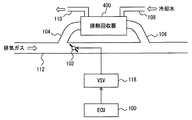
図2に示すように、排気ガスが流通する排気通路112には、排気通路112に並列に接続されたバイパス通路104,106と、バイパス通路104,106の間に設けられる排熱回収器400と、排気通路112の途中に設けられる切換弁102とが設けられる。
As shown in FIG. 2, the
排気通路112には、バイパス通路104との分岐後であって、バイパス通路106との合流前の位置に切換弁102が設けられる。切換弁102が閉じられると、切換弁102により通路が遮断される。このとき、排気通路112を通る排気ガスは、バイパス通路104を流通する。排気ガスは、排熱回収器400を通過した後、バイパス通路106を通過して、排気通路112に再び合流する。切換弁102が開いたときには、バイパス通路104側に排気ガスが流れないような構造を有する。たとえば、切換弁102が開くと、バイパス通路104側の通路が閉じる構造を有してもよいし、バイパス通路104の通路断面積を小さくすることにより通気抵抗を大きくして、切換弁102が開くと、排気通路112側に排気ガスが流れるようにしてもよいが、特にこれらの構造に限定されるものではない。
A switching
切換弁102は、VSV(Vacuum Switching Valve)118により作動し、ECU100がVSVの作動を制御することにより、切換弁102の開閉状態が制御される。なお、VSVに代えてアクチュエータを用いるようにしてもよい。
The switching
排熱回収器400は、熱交換器(図示せず)と、熱交換器に媒体を流通させる媒体通路とから構成される。媒体通路は、熱交換器に媒体を導入する上流側通路108と、熱交換器から媒体を導出する下流側通路110とを含む。上流側通路108は、ヒータコア300の下流側に接続され、下流側通路110は、電動ウォータポンプ600の上流側に接続される。ECU100は、エンジン200の始動時の暖機初期時において、切換弁102が閉じるように制御する。具体的には、ECU100は、たとえば、水温センサ900により検知される冷却水の温度が予め定められた温度以下であると、切換弁102を閉じるように制御する。切換弁102が閉じられると、バイパス通路104に排気ガスが流通して、熱交換器である排熱回収器400において、排気ガスの熱エネルギが回収される。具体的には、排熱回収器400と排気ガスが接触することにより、排気ガスと排熱回収器との間で熱交換されて、排熱回収器に流通する冷却媒体の温度が上昇する。
The exhaust
排熱回収器400を流通する冷却媒体の流量、および、冷却媒体と排気ガスとの熱交換の効率は、図3に示すような関係を有する。
The flow rate of the cooling medium flowing through the exhaust
すなわち、図3に示すように、横軸を排熱回収器400における冷却媒体の流量とし、縦軸を熱交換効率とすると、熱交換効率は冷却媒体の流量の増加とともに増加していくが、冷却媒体の流量が増加するほど熱交換効率の増加量が減少していく。すなわち、熱交換効率は、ある値に収束する。
That is, as shown in FIG. 3, when the horizontal axis is the flow rate of the cooling medium in the exhaust
このような構成を有するエンジンの冷却装置において、エンジン200が冷間時であるときに、エンジン200が始動されたときには、ヒータの作動要求があると、ヒータ性能を確保するために、冷却媒体の温度を速やかに上昇させる必要がある。しかしながら、たとえば、電動ウォータポンプ600を最大回転数で回転させようとすると、冷間始動後に温度の低い冷却媒体が流通するため、エンジン200の燃焼により発生した熱エネルギは流通する冷却媒体に奪われる。そのため、エンジン200の温度が上昇しにくいという問題がある。エンジン200の温度が低いと燃焼が安定しないため、燃費が悪化する場合がある。一方、ヒータの作動要求があるときにエンジン200の暖機を優先して、電動ウォータポンプ600を停止あるいは最小回転数になるようにすると、ヒータコア300における冷却媒体の温度が上昇しにくいため、ヒータの性能を確保できない可能性がある。
In the engine cooling apparatus having such a structure, when the
また、電動ウォータポンプ600による流量と排熱回収器400における熱交換効率とは比例しないため、電動ウォータポンプ600を最大回転数で回転させる場合、消費電力が増加するなどして燃費が悪化する可能性がある。
In addition, since the flow rate by the
本実施の形態においては、ECU100が、排熱回収器400などの熱交換器における熱交換効率と、冷却媒体の流量に対応する電動ウォータポンプ600における電力との関係に基づいて流量を設定し、設定された流量の冷却媒体が流通するように電動ウォータポンプ600に供給される電力を制御する点に特徴を有する。本実施の形態に係るエンジンの冷却装置は、ECU100が実行するプログラムにより実現される。
In the present embodiment, the
具体的には、ECU100は、エンジン200の冷間始動後に、ヒータの作動要求があると、エンジン200において要求される流量と、ヒータコア300において要求される流量と、排熱回収器400において要求される流量とのうちのいずれか大きい流量を設定する。
Specifically, when there is a heater operation request after the
ここで、「エンジン200において要求される流量」は、エンジン200の温度が予め定められた範囲内の温度になるために必要な流量である。エンジン200の温度は、たとえば、水温センサ900により検知された媒体通路806における冷却媒体の温度に基づいて推定するようにしてもよい。
Here, “the flow rate required in the
「ヒータコア300において要求される流量」は、ヒータ性能を満たす最低限の流量である。ヒータ性能を最低限確保するために必要な流量は、実験等により適合される。「排熱回収器400において要求される流量」は、図3に示したように、熱交換効率と流量との関係に基づいて、電動ウォータポンプ600の消費電力の増加を抑制しつつ、必要な熱効率が確保できる流量(たとえば、熱交換効率A(0)−A(1)の範囲に対応するV(1)−V(2)の範囲内の流量)である。ECU100は、設定された流量の冷却媒体が流通するように電動ウォータポンプ600に供給される電力を制御する。
The “flow rate required in the
図4を参照して、本実施の形態に係るエンジンの冷却装置において、ECU100が実行するプログラムの制御構造について説明する。
With reference to FIG. 4, a control structure of a program executed by
ステップ(以下、ステップをSと略す)100にて、ECU100は、エンジン200が冷間時であるか否かを判断する。ECU100は、たとえば、冷却媒体の温度が予め定められた温度以下であると、エンジン200が冷間時であると判断するようにしてもよい。または、ECU100は、エンジン200が始動してから予め定められた時間が経過していなければエンジン200が冷間時であると判断するようにしてもよい。あるいは、ECU100は、水温センサ900により検知された冷却媒体の温度に基づいてエンジン200自体の温度を推定して、推定された温度が予め定められた温度以下であると、エンジン200が冷間時であると判断するようにしてもよい。エンジン200自体の温度の推定は周知の技術を用いればよく、その詳細は説明しない。エンジン200が冷間時であると(S100にてYES)、処理はS102に移される。もしそうでないと(S100にてNO)、処理はS108に移される。
In step (hereinafter step is abbreviated as S) 100,
S102にて、ECU100は、ヒータの作動要求があるか否かを判断する。ECU100は、運転者によるヒータの作動に対応する操作が行なわれたことを検知することにより、ヒータの作動要求があると判断するようにしてもよい。あるいは、ECU100は、自動空調装置(図示せず)が車室内の温度が上昇するように制御する時に、ヒータの作動要求があると判断するようにしてもよい。ヒータの作動要求があると(S102にてYES)、処理はS106に移される。もしそうでないと(S102にてNO)、処理はS104に移される。
In S102,
S104にて、ECU100は、電動ウォータポンプ600を停止するように電力を制御する。なお、本実施の形態において、ECU100は、冷却媒体を流通しないように流量を設定するが、特に限定されるものではなく、たとえば、予め定められた設定された範囲の流量のうちの最小の流量になるように電力を制御するようにしてもよい。
In S104,
S106にて、ECU100は、(1)エンジン200において要求される流量と、(2)ヒータコア300において要求される流量と、(3)排熱回収器400において要求される流量とのうちのいずれか大きい方の流量を設定する。(1)〜(3)の要求流量については、上述した通りであるため、その詳細な説明は繰り返さない。ECU100は、設定された流量になるように電動ウォータポンプ600に供給される電力を制御する。
In S106,
S108にて、ECU100は、電動ウォータポンプ600の通常制御を行なう。すなわち、ECU100は、エンジン200において要求される流量になるように電動ウォータポンプ600に供給される電力を制御する。このとき、ECU100は、エンジン200の温度が予め定められた範囲内の温度になるように電動ウォータポンプ600を制御する。
In S108,
以上のような構成およびフローチャートに基づく、本実施の形態におけるECU100の動作について説明する。
An operation of
運転者がイグニッションキーをオンし、エンジン200を始動したときに、冷却媒体の温度が予め定められた温度よりも低いと(S100にてYES)、排気ガスが排熱回収器400に導かれるように切換弁102が切り換わる。排気ガスが排熱回収器400に導かれると、排気ガスの熱により排熱回収器400内の冷却媒体の温度が上昇する。このとき、ヒータの作動要求がない場合には(S102にてNO)、電動ウォータポンプ600は停止するように電力が制御される(S104)。エンジン200内の媒体通路の冷却媒体は流通しないため、エンジン200の作動により発生した熱はエンジン200内の冷却媒体とともに、エンジン200自体の温度を上昇させる。
When the driver turns on the ignition key and starts
一方、冷却媒体の温度が予め定められた温度よりも低いときに(S100にてYES)、ヒータの作動要求があると(S102にてYES)、エンジン200において要求される流量と、ヒータコア300において要求される流量と、排熱回収器400において要求される流量とのうちのいずれか大きい流量が設定される。そして、ECU100により設定された流量になるように電動ウォータポンプ600に供給される電力が制御される(S106)。このとき、少なくともヒータ性能を満たす最低限の流量が設定されるため、流量不足によりヒータの性能が低下することはない。
On the other hand, when the temperature of the cooling medium is lower than a predetermined temperature (YES in S100), if there is a heater operation request (YES in S102), the flow rate required in
また、運転者がエンジン200を始動したときに、冷却媒体の温度が予め定められた温度よりも高いと(S100にてNO)、切換弁102が切り換わらないため、排気ガスは排熱回収器400に導かれない。このとき、エンジン200において要求される流量、すなわち、エンジン200の温度が予め定められた範囲内の温度になるために必要な流量の冷却媒体が流通するように、電動ウォータポンプ600に供給される電力が制御される(S108)。
Further, when the driver starts
以上のようにして、本実施の形態に係るエンジンの冷却装置によると、ECUは、排熱回収器における熱交換効率と電動ウォータポンプの電力との関係に基づいて、消費電力の増加を抑制しつつ排熱回収器において必要な熱交換効率を確保できる流量を設定する。これにより、消費電力の増加による燃費の悪化と流量が不足して熱交換効率が悪化することによる排熱回収器の性能の低下とを抑制することができる。したがって、エンジンの燃費の悪化の抑制とエンジンの冷却媒体が流通する熱交換器における流量の効率化とを両立するエンジンの冷却装置を提供することができる。 As described above, according to the engine cooling device according to the present embodiment, the ECU suppresses an increase in power consumption based on the relationship between the heat exchange efficiency in the exhaust heat recovery device and the power of the electric water pump. While setting the flow rate that can secure the required heat exchange efficiency in the exhaust heat recovery unit. Thereby, the deterioration of the fuel consumption due to the increase in power consumption and the deterioration of the performance of the exhaust heat recovery device due to the deterioration of the heat exchange efficiency due to the insufficient flow rate can be suppressed. Therefore, it is possible to provide an engine cooling device that achieves both suppression of deterioration of the fuel consumption of the engine and efficiency improvement of the flow rate in the heat exchanger in which the engine coolant flows.
また、ヒータの作動要求があると、ヒータコアにおいて要求される流量、エンジンにおいて要求される流量および排熱回収器において要求される流量のうちのいずれか大きい方の流量を設定する。そのため、ヒータの作動要求があったときには、少なくともヒータの性能を満たす最低限の流量が設定されるため、ヒータ性能の低下を抑制しつつ、エンジンの暖機を促進することができる。さらに、ECUは、エンジンが冷間時でないと、エンジンの作動に応じて要求される流量を設定する。これにより、エンジンの温度を適切に維持することができる。 Further, when there is a heater operation request, the larger one of the flow rate required in the heater core, the flow rate required in the engine, and the flow rate required in the exhaust heat recovery unit is set. Therefore, when there is a heater operation request, a minimum flow rate that satisfies at least the performance of the heater is set. Therefore, it is possible to promote engine warm-up while suppressing a decrease in the heater performance. Further, when the engine is not cold, the ECU sets a flow rate required according to the operation of the engine. Thereby, the temperature of an engine can be maintained appropriately.
なお、本実施の形態に係るエンジンの冷却装置が搭載された車両において、エンジンの始動は運転者により行なわれることとして説明したが、エンジンが搭載される車両であれば特にこれに限定されるものではない。たとえば、車両は、ハイブリッド車両やアイドリングストップ車両であってもよく、エンジン200は、予め定められた始動条件が成立すると始動するようにしてもよい。
In addition, in the vehicle equipped with the engine cooling device according to the present embodiment, it has been described that the engine is started by the driver. However, the vehicle is particularly limited to this as long as the vehicle is equipped with the engine. is not. For example, the vehicle may be a hybrid vehicle or an idling stop vehicle, and
<第2の実施の形態>
以下、本発明の第2の実施の形態に係るエンジンの冷却装置について説明する。本実施の形態に係るエンジンの冷却装置は、上述の第1の実施の形態に係るエンジンの冷却装置の構成と比較して、ECU100が実行するプログラムの制御構造が異なる。それ以外の構成は、上述の第1の実施の形態に係るエンジンの冷却装置の構成と同じ構成である。それらについては同じ参照符号が付してある。それらの機能も同じである。したがって、それらについての詳細な説明はここでは繰り返さない。
<Second Embodiment>
Hereinafter, an engine cooling apparatus according to a second embodiment of the present invention will be described. The engine cooling device according to the present embodiment differs from the configuration of the engine cooling device according to the first embodiment described above in the control structure of the program executed by
図5を参照して、本実施の形態に係るエンジンの冷却装置において、ECU100が実行するプログラムの制御構造について説明する。なお、図5に示したフローチャートの中で、前述の図4に示したフローチャートと同じ処理については同じステップ番号を付してある。それらについて処理も同じである。したがって、それらについての詳細な説明はここでは繰り返さない。
With reference to FIG. 5, a control structure of a program executed by
S200にて、ECU100は、ヒータの作動要求があると(S102にてYES)、すなわち、ヒータがオンされると、ヒータがオンされた後予め定められた時間が経過したか否かを判断する。ヒータがオンされてから予め定められた時間が経過すると(S200にてYES)、処理はS106に移される。もしそうでないと(S200にてNO)、処理はS202に移される。
In S200, when there is a heater operation request (YES in S102), that is, when the heater is turned on, that is, when the heater is turned on,
S202にて、ECU100は、エンジン200の温度が予め定められた温度以上であるか否かを判断する。なお、ECU100は、水温センサ900により検知されたエンジン200を流通する冷却媒体の温度が予め定められた温度以上であるか否かを判断するようにしてもよい。エンジン200の温度が予め定められた温度以上であると(S202にてYES)、処理はS106に移される。もしそうでないと(S202にてNO)、処理はS104に移される。
In S202,
以上のような構造およびフローチャートに基づく、本実施の形態におけるECU100の動作について説明する。
An operation of
運転者がイグニッションキーをオンし、エンジン200を始動したときに、冷却媒体の温度が予め定められた温度よりも低いと(S100にてYES)、排気ガスが排熱回収器400に導かれるように切換弁102が切り換わる。排気ガスが排熱回収器400に導かれると、排気ガスの熱により排熱回収器400内の冷却媒体の温度が上昇する。
When the driver turns on the ignition key and starts
このとき、ヒータの作動要求がない場合には(S102にてNO)、電動ウォータポンプ600は停止するように電力が制御される(S104)。エンジン200内の媒体通路の冷却媒体は流通しないため、エンジン200の作動により発生した熱はエンジン200内の冷却媒体とともに、エンジン200自体の温度を上昇させる。
At this time, if there is no heater activation request (NO in S102), electric power is controlled so that
一方、冷却媒体の温度が予め定められた温度よりも低いときに(S100にてYES)、ヒータの作動要求があると(S102にてYES)、予め定められた時間が経過するか(S200にてYES)、あるいは、予め定められた時間が経過していなくても(S200にてNO)、エンジン200の温度が予め定められた温度以上であると(S202にてYES)、エンジン200において要求される流量と、ヒータコア300において要求される流量と、排熱回収器400において要求される流量とのうちのいずれか大きい流量が設定される。そして、ECU100により設定された流量になるように電動ウォータポンプ600に供給される電力が制御される(S106)。このとき、少なくともヒータ性能を満たす最低限の流量が設定されるため、流量不足によりヒータの性能が低下することはない。
On the other hand, when the temperature of the cooling medium is lower than the predetermined temperature (YES in S100), if there is a heater operation request (YES in S102), does the predetermined time elapse (in S200)? YES, or even if the predetermined time has not elapsed (NO in S200), if the temperature of
また、ヒータの作動要求があっても(S102にてYES)、予め定められた時間が経過せず(S200にてNO)、エンジン200の温度も予め定められた温度以上でないと(S202にてNO)、電動ウォータポンプ600は停止するように電力が制御される(S104)。
Further, even if there is a heater operation request (YES in S102), a predetermined time does not elapse (NO in S200), and the temperature of
また、運転者がエンジン200を始動したときに、冷却媒体の温度が予め定められた温度よりも高いと(S100にてNO)、切換弁102が切り換わらないため、排気ガスは排熱回収器400に導かれない。このとき、エンジン200において要求される流量、すなわち、エンジン200の温度が予め定められた範囲内の温度になるために必要な流量の冷却媒体が流通するように、電動ウォータポンプ600に供給される電力が制御される(S108)。
Further, when the driver starts
以上のようにして、本実施の形態に係るエンジンの冷却装置によると、上述した第1の実施の形態に係るエンジンの冷却装置が有する効果に加えて、エンジンの冷間始動後に、ヒータの作動要求があった後、予め定められた時間が経過するまでの間は、冷却媒体が媒体通路を循環しないように、流量を制御するため、エンジン自体の温度を速やかに上昇させることができる。そのため、ヒータがオンされてから予め定められた時間が経過するまでの間、エンジンの暖機を優先させることができる。そのため、エンジン自体の温度を速やかに上昇させることができるため、燃費の悪化を抑制することができる。 As described above, according to the engine cooling apparatus according to the present embodiment, in addition to the effects of the engine cooling apparatus according to the first embodiment described above, the heater operation is performed after the engine is cold started. Since the flow rate is controlled so that the cooling medium does not circulate through the medium passage after the request is made until a predetermined time elapses, the temperature of the engine itself can be quickly raised. Therefore, priority can be given to warming up the engine until a predetermined time elapses after the heater is turned on. Therefore, since the temperature of the engine itself can be quickly raised, deterioration of fuel consumption can be suppressed.
<第3の実施の形態>
以下、本発明の第3の実施の形態に係るエンジンの冷却装置について説明する。本実施の形態に係るエンジンの冷却装置は、上述の第1の実施の形態に係るエンジンの冷却装置の構成と比較して、ECU100が実行するプログラムの制御構造が異なる。それ以外の構成は、上述の第1の実施の形態に係るエンジンの冷却装置の構成と同じ構成である。それらについては同じ参照符号が付してある。それらの機能も同じである。したがって、それらについての詳細な説明はここでは繰り返さない。
<Third Embodiment>
Hereinafter, an engine cooling apparatus according to a third embodiment of the present invention will be described. The engine cooling device according to the present embodiment differs from the configuration of the engine cooling device according to the first embodiment described above in the control structure of the program executed by
図6を参照して、本実施の形態に係るエンジンの冷却装置において、ECU100が実行するプログラムの制御構造について説明する。なお、図6に示したフローチャートの中で、前述の図5に示したフローチャートと同じ処理については同じステップ番号を付してある。それらについて処理も同じである。したがって、それらについての詳細な説明はここでは繰り返さない。
With reference to FIG. 6, a control structure of a program executed by
S300にて、ヒータの作動要求がないと(S102にてNO)、ECU100は、排熱回収状態と電動ウォータポンプ600の停止によるエンジン200の暖機状態との比較結果に基づいて、電動ウォータポンプ600の停止が有利であるか否かを判断する。電動ウォータポンプ600の停止が有利であるか否かは、たとえば、エンジン200がアイドル回転数であるときの排熱回収状態(たとえば、回収熱量)と、エンジン200の暖機状態(たとえば、エンジン200の温度)との比較に基づいて、効率あるいは燃費の点で有利であるのはいずれかという観点で判断される。アイドル回転時における排熱回収状態とエンジン200の暖機状態とのうちいずれか有利であるかについて、ECU100は、たとえば、回収熱量とエンジン200の温度(あるいは、エンジン200内の冷却媒体の温度)との関係を、実験等によりマップなどとして記憶しておき、マップに排熱回収が有利な領域とエンジン暖機が有利な領域とを設定しておくことにより判断するようにしてもよい。すなわち、ECU100は、エンジン回転数センサ(図示せず)により検知されたエンジン200の回転数と水温センサ900により検知された温度に基づくエンジン200の温度とが排熱回収が有利な領域内であるかエンジン暖機が有利な領域内であるかを判断するようにしてもよい。電動ウォータポンプ600の停止が有利であると判断されると(S300にてYES)、処理はS104に移される。もしそうでないと(S300にてNO)、処理はS106に移される。
If there is no heater activation request in S300 (NO in S102),
以上のような構造およびフローチャートに基づく、本実施の形態におけるECU100の動作について説明する。
An operation of
運転者がイグニッションキーをオンし、エンジン200を始動したときに、冷却媒体の温度が予め定められた温度よりも低いと(S100にてYES)、排気ガスが排熱回収器400に導かれるように切換弁102が切り換わる。排気ガスが排熱回収器400に導かれると、排気ガスの熱により排熱回収器400内の冷却媒体の温度が上昇する。
When the driver turns on the ignition key and starts
このとき、ヒータの作動要求がない場合には(S102にてNO)、排熱回収器400の排熱回収状態(アイドル回転時における回収熱量)とエンジン200の暖機状態(エンジン200の温度)とに基づいて、電動ウォータポンプ600を停止させることが有利であると判断されると(S300にてYES)、電動ウォータポンプ600は停止するように電力が制御される(S104)。エンジン200内の媒体通路の冷却媒体は流通しないため、エンジン200の作動により発生した熱はエンジン200内の冷却媒体とともに、エンジン200自体の温度を上昇させる。
At this time, if there is no heater activation request (NO in S102), the exhaust heat recovery state (recovered heat amount during idle rotation) of the exhaust
電動ウォータポンプ600の停止が有利でないと判断されると(S300にてNO)、エンジン200において要求される流量と、ヒータコア300において要求される流量と、排熱回収器400において要求される流量とのうちのいずれか大きい流量が設定される。このとき、ヒータの作動要求がないため、ECU100は、エンジン200において要求される流量と、排熱回収器400において要求される流量とのうちのいずれか大きい流量を設定する。そして、ECU100により設定された流量になるように電動ウォータポンプ600に供給される電力が制御される(S106)。冷却媒体は媒体通路を流通し、冷却媒体の温度は、排熱回収器400において回収される熱と、エンジン200の作動により発生する熱により上昇する。
If it is determined that stopping
一方、冷却媒体の温度が予め定められた温度よりも低いときに(S100にてYES)、ヒータの作動要求があると(S102にてYES)、予め定められた時間が経過するか(S200にてYES)、あるいは、予め定められた時間が経過していなくても(S200にてNO)、エンジン200の温度が予め定められた温度以上であると(S202にてYES)、エンジン200において要求される流量と、ヒータコア300において要求される流量と、排熱回収器400において要求される流量とのうちのいずれか大きい流量が設定される。そして、ECU100により設定された流量になるように電動ウォータポンプ600に供給される電力が制御される(S106)。このとき、少なくともヒータ性能を満たす最低限の流量が設定されるため、流量不足によりヒータの性能が低下することはない。
On the other hand, when the temperature of the cooling medium is lower than the predetermined temperature (YES in S100), if there is a heater operation request (YES in S102), does the predetermined time elapse (in S200)? YES, or even if the predetermined time has not elapsed (NO in S200), if the temperature of
また、ヒータの作動要求があっても(S102にてYES)、予め定められた時間が経過せず(S200にてNO)、エンジン200の温度も予め定められた温度以上でないと(S202にてNO)、電動ウォータポンプ600は停止するように電力が制御される(S104)。
Further, even if there is a heater operation request (YES in S102), a predetermined time does not elapse (NO in S200), and the temperature of
また、運転者がエンジン200を始動したときに、冷却媒体の温度が予め定められた温度よりも高いと(S100にてNO)、切換弁102が切り換わらないため、排気ガスは排熱回収器400に導かれない。このとき、エンジン200において要求される流量、すなわち、エンジン200の温度が予め定められた範囲内の温度になるために必要な流量の冷却媒体が流通するように、電動ウォータポンプ600に供給される電力が制御される(S108)。
Further, when the driver starts
以上のようにして、本実施の形態に係るエンジンの冷却装置によると、上述した第2の実施の形態に係るエンジンの冷却装置が有する効果に加えて、ECUは、エンジンの冷間時におけるエンジン自体の温度と回収熱量との関係に基づいて、エンジンの暖機および排熱回収のうちのいずれが効率あるいは燃費の点で有利であるかを判断するため、エンジンの暖機が有利であると判断される場合に、冷却媒体の流通を停止することにより、エンジン自体の温度を速やかに上昇させることができる。また、排熱の回収が有利であると判断される場合に、排熱回収が効率よく行なうことができる流量で冷却媒体を流通させることにより、冷却媒体の温度を効率よく上昇させることができる。すなわち、エンジンの暖機状態と排熱回収状態に応じて流量が設定されるため、効率よく暖機を行なうことができる。したがって、エンジンの燃費の悪化の抑制とエンジンの冷却媒体が流通する熱交換器における流量の効率化とを両立するエンジンの冷却装置を提供することができる。 As described above, according to the engine cooling device according to the present embodiment, in addition to the effects of the engine cooling device according to the second embodiment described above, the ECU Based on the relationship between the temperature of itself and the amount of recovered heat, it is determined which of engine warm-up and exhaust heat recovery is advantageous in terms of efficiency or fuel consumption. When the determination is made, the temperature of the engine itself can be quickly raised by stopping the flow of the cooling medium. In addition, when it is determined that the recovery of exhaust heat is advantageous, the temperature of the cooling medium can be efficiently increased by circulating the cooling medium at a flow rate that allows efficient exhaust heat recovery. That is, since the flow rate is set according to the warm-up state of the engine and the exhaust heat recovery state, warm-up can be performed efficiently. Therefore, it is possible to provide an engine cooling device that achieves both suppression of deterioration of the fuel consumption of the engine and efficiency improvement of the flow rate in the heat exchanger in which the engine coolant flows.
今回開示された実施の形態はすべての点で例示であって制限的なものではないと考えられるべきである。本発明の範囲は上記した説明ではなくて特許請求の範囲によって示され、特許請求の範囲と均等の意味および範囲内でのすべての変更が含まれることが意図される。 The embodiment disclosed this time should be considered as illustrative in all points and not restrictive. The scope of the present invention is defined by the terms of the claims, rather than the description above, and is intended to include any modifications within the scope and meaning equivalent to the terms of the claims.
100 ECU、102 切換弁、104,106 バイパス通路、108 上流側通路、110 下流側通路、112 排気通路、118 VSV、200 エンジン、202 シリンダブロック、204 シリンダヘッド、300 ヒータコア、400 排熱回収器、500 ラジエータ、600 電動ウォータポンプ、700 サーモスタット、800,802,804 媒体通路、900 水温センサ。 100 ECU, 102 switching valve, 104, 106 bypass passage, 108 upstream passage, 110 downstream passage, 112 exhaust passage, 118 VSV, 200 engine, 202 cylinder block, 204 cylinder head, 300 heater core, 400 exhaust heat recovery device, 500 radiator, 600 electric water pump, 700 thermostat, 800, 802, 804 medium passage, 900 water temperature sensor.
Claims (6)
電力の供給を受けて前記冷却媒体を循環させるための循環手段と、
前記循環手段に供給される電力を制御するための制御手段とを含み、
前記制御手段は、
前記エンジンの冷間時において、前記熱交換器における熱交換効率と、前記冷却媒体の流量に対応する前記循環手段における電力との関係に基づいて、前記流量を設定するための設定手段と、
前記設定された流量になるように前記電力を制御するための手段とを含む、エンジンの冷却装置。 A cooling device for adjusting the temperature of the engine, wherein the engine is provided with a medium passage through which a cooling medium flows, and the medium passage is connected to a heat exchanger that exchanges heat with the cooling medium,
Circulating means for circulating the cooling medium in response to power supply;
Control means for controlling the power supplied to the circulation means,
The control means includes
Setting means for setting the flow rate based on the relationship between the heat exchange efficiency in the heat exchanger and the electric power in the circulation means corresponding to the flow rate of the cooling medium when the engine is cold;
Means for controlling the electric power so as to achieve the set flow rate.
電力の供給を受けて前記冷却媒体を循環させるための循環手段と、
前記循環手段に供給される電力を制御するための制御手段とを含み、
前記制御手段は、
前記エンジンの冷間時において、前記排熱回収器における熱交換効率と、前記冷却媒体の流量に対応する前記循環手段における電力との関係に基づいて、前記流量を設定するための設定手段と、
前記設定された流量になるように前記電力を制御するための手段とを含む、エンジンの冷却装置。 A cooling device for adjusting a temperature of an engine, wherein the engine is provided with a medium passage through which a cooling medium flows, and the medium passage includes the exhaust gas of the engine provided in the exhaust passage of the engine and the cooling It is connected to an exhaust heat recovery unit that recovers exhaust heat by heat exchange with the medium,
Circulating means for circulating the cooling medium in response to power supply;
Control means for controlling the power supplied to the circulation means,
The control means includes
Setting means for setting the flow rate based on the relationship between the heat exchange efficiency in the exhaust heat recovery unit and the electric power in the circulation means corresponding to the flow rate of the cooling medium when the engine is cold;
Means for controlling the electric power so as to achieve the set flow rate.
前記冷却媒体を循環させるための循環手段と、
前記循環手段により循環する冷却媒体の流量を制御するための制御手段とを含み、
前記制御手段は、
前記エンジンの冷間時において、前記エンジンの暖機状態と、前記排熱回収器における排熱回収状態との比較結果に基づいて、前記流量を設定するための設定手段と、
前記設定された流量になるように前記流量を制御するための手段とを含む、エンジンの冷却装置。 A cooling device for adjusting a temperature of an engine, wherein the engine is provided with a medium passage through which a cooling medium flows, and the medium passage includes the exhaust gas of the engine provided in the exhaust passage of the engine and the cooling It is connected to an exhaust heat recovery unit that recovers exhaust heat by heat exchange with the medium,
Circulating means for circulating the cooling medium;
Control means for controlling the flow rate of the cooling medium circulated by the circulation means,
The control means includes
Setting means for setting the flow rate based on a comparison result between the warm-up state of the engine and the exhaust heat recovery state in the exhaust heat recovery unit when the engine is cold;
Means for controlling the flow rate to achieve the set flow rate.
前記制御手段は、前記ヒータの作動要求があると、前記ヒータコアにおいて要求される流量と、前記エンジンの冷間時に要求される流量とのうちのいずれか大きい方の流量を設定するための手段を含む、請求項2または3に記載のエンジンの冷却装置。 The medium passage is connected to a heater core that performs heat exchange between air in the vehicle room and the cooling medium,
The control means has means for setting a larger one of a flow rate required in the heater core and a flow rate required when the engine is cold when the heater is requested to operate. The cooling device for an engine according to claim 2 or 3, further comprising:
Priority Applications (5)
| Application Number | Priority Date | Filing Date | Title |
|---|---|---|---|
| JP2005200323A JP2007016718A (en) | 2005-07-08 | 2005-07-08 | Engine cooling device |
| US11/886,947 US20090229543A1 (en) | 2005-07-08 | 2006-07-05 | Cooling device for engine |
| CNA2006800248068A CN101218422A (en) | 2005-07-08 | 2006-07-05 | Engine cooler |
| EP06780986A EP1903193A1 (en) | 2005-07-08 | 2006-07-05 | Engine cooler |
| PCT/JP2006/313816 WO2007007775A1 (en) | 2005-07-08 | 2006-07-05 | Engine cooler |
Applications Claiming Priority (1)
| Application Number | Priority Date | Filing Date | Title |
|---|---|---|---|
| JP2005200323A JP2007016718A (en) | 2005-07-08 | 2005-07-08 | Engine cooling device |
Publications (1)
| Publication Number | Publication Date |
|---|---|
| JP2007016718A true JP2007016718A (en) | 2007-01-25 |
Family
ID=37637165
Family Applications (1)
| Application Number | Title | Priority Date | Filing Date |
|---|---|---|---|
| JP2005200323A Pending JP2007016718A (en) | 2005-07-08 | 2005-07-08 | Engine cooling device |
Country Status (5)
| Country | Link |
|---|---|
| US (1) | US20090229543A1 (en) |
| EP (1) | EP1903193A1 (en) |
| JP (1) | JP2007016718A (en) |
| CN (1) | CN101218422A (en) |
| WO (1) | WO2007007775A1 (en) |
Cited By (8)
| Publication number | Priority date | Publication date | Assignee | Title |
|---|---|---|---|---|
| JP2008274885A (en) * | 2007-05-01 | 2008-11-13 | Toyota Motor Corp | Cooling device for internal combustion engine |
| JP2009150266A (en) * | 2007-12-19 | 2009-07-09 | Toyota Motor Corp | Cooling water controller of internal combustion engine |
| JP2009167917A (en) * | 2008-01-16 | 2009-07-30 | Denso Corp | Warmup promoting device |
| JP2010190050A (en) * | 2009-02-16 | 2010-09-02 | Toyota Motor Corp | Cooling control device of internal combustion engine |
| JP2011111910A (en) * | 2009-11-24 | 2011-06-09 | Aisin Seiki Co Ltd | Engine cooling device |
| US8347846B2 (en) | 2009-06-09 | 2013-01-08 | Toyota Jidosha Kabushiki Kaisha | Control device for internal combustion engine |
| JP2014037785A (en) * | 2012-08-13 | 2014-02-27 | Toyota Motor Corp | Cooling water control device |
| JP2015110919A (en) * | 2013-12-06 | 2015-06-18 | マツダ株式会社 | Engine cooling device and cooling method |
Families Citing this family (31)
| Publication number | Priority date | Publication date | Assignee | Title |
|---|---|---|---|---|
| EP1862526B1 (en) | 2006-05-31 | 2009-10-14 | Chisso Corporation | Liquid crystal compositions and liquid crystal display device |
| JP2008231942A (en) * | 2007-03-16 | 2008-10-02 | Toyota Motor Corp | Cooling system of internal combustion engine |
| EP2014889A1 (en) * | 2007-06-20 | 2009-01-14 | Ford Global Technologies, LLC | A method for thermally managing an internal combustion engine |
| JP2010119282A (en) * | 2008-10-17 | 2010-05-27 | Denso Corp | Thermal management system |
| US9097172B2 (en) * | 2009-09-03 | 2015-08-04 | GM Global Technology Operations LLC | Switchable water pump control systems and methods |
| JP5447644B2 (en) * | 2010-02-26 | 2014-03-19 | トヨタ自動車株式会社 | Control device for internal combustion engine |
| CN103174504B (en) | 2010-03-03 | 2015-11-18 | 株式会社电装 | For the controller of engine-cooling system |
| DE102010002605B4 (en) | 2010-03-05 | 2013-12-12 | Ford Global Technologies, Llc | Method for shortening the warm-up phase by means of heat recovery from recirculated exhaust gases |
| WO2011111159A1 (en) * | 2010-03-09 | 2011-09-15 | トヨタ自動車 株式会社 | Engine cooling device |
| DE102010015107B4 (en) * | 2010-04-16 | 2014-01-02 | Audi Ag | Coolant circuit for an internal combustion engine of a motor vehicle |
| KR20110120766A (en) * | 2010-04-29 | 2011-11-04 | 현대자동차주식회사 | Apparatus for control water pump of hybrid vehicle and method thereof |
| US8746185B2 (en) * | 2010-09-08 | 2014-06-10 | Toyota Jidosha Kabushiki Kaisha | Engine control device and engine control method |
| US8997847B2 (en) | 2010-09-10 | 2015-04-07 | Ford Global Technologies, Llc | Cooling in a liquid-to-air heat exchanger |
| EP2607643B1 (en) * | 2010-11-12 | 2018-01-24 | Aisin Seiki Kabushiki Kaisha | Control valve |
| US8991338B2 (en) * | 2010-12-24 | 2015-03-31 | Toyota Jidosha Kabushiki Kaisha | Vehicle and method for controlling the same |
| JP5505331B2 (en) * | 2011-02-23 | 2014-05-28 | 株式会社デンソー | Internal combustion engine cooling system |
| WO2012148565A1 (en) * | 2011-02-28 | 2012-11-01 | Cummins Intellectual Property, Inc. | Ejector coolant pump for internal combustion engine |
| US9297292B2 (en) * | 2011-07-20 | 2016-03-29 | Toyota Jidosha Kabushiki Kaisha | Engine cooling device |
| US20130094972A1 (en) * | 2011-10-18 | 2013-04-18 | Ford Global Technologies, Llc | Climate Thermal Load Based Minimum Flow Rate Water Pump Control |
| DE102011085961A1 (en) * | 2011-11-08 | 2013-05-08 | Behr Gmbh & Co. Kg | Cooling circuit |
| CN102536582A (en) * | 2012-01-13 | 2012-07-04 | 浙江吉利汽车研究院有限公司 | Preheating device of engine |
| US9869232B2 (en) * | 2012-06-27 | 2018-01-16 | Ford Global Technologies, Llc | Variable-speed pump control for engine coolant system with variable restriction |
| US20140000859A1 (en) * | 2012-06-27 | 2014-01-02 | Ford Global Technologies, Llc | Variable-speed pump control for combustion engine coolant system |
| CN103543027B (en) * | 2013-10-29 | 2016-03-30 | 浙江吉利控股集团有限公司 | A kind of automatic checkout system of thermostat working temperature |
| SE537027C2 (en) * | 2013-12-20 | 2014-12-09 | Scania Cv Ab | Cooling arrangement for cooling at least one cylinder of a single-combustion engine |
| US20170248065A1 (en) * | 2014-08-19 | 2017-08-31 | Borgwarner Inc. | Thermal management system and method ofmaking and using the same |
| WO2016071556A1 (en) * | 2014-11-04 | 2016-05-12 | Wärtsilä Finland Oy | Internal combustion piston engine and method of operating an internal combustion piston engine |
| US10471793B2 (en) | 2016-10-12 | 2019-11-12 | Ford Global Technologies, Llc | Seat mounts for side load spring on a twist beam axle |
| US20180128145A1 (en) * | 2016-11-09 | 2018-05-10 | Ford Global Technologies, Llc | Method and system for an exhaust diverter valve |
| CN106870100B (en) * | 2017-02-17 | 2019-07-23 | 广州汽车集团股份有限公司 | A kind of control method and device of engine clutch type water pump |
| CN111412099B (en) * | 2019-01-08 | 2021-04-02 | 广州汽车集团股份有限公司 | Method and system for quickly warming automobile |
Citations (6)
| Publication number | Priority date | Publication date | Assignee | Title |
|---|---|---|---|---|
| JPS57171022A (en) * | 1981-04-15 | 1982-10-21 | Mazda Motor Corp | Controlling device of water pump of engine |
| JPS635108A (en) * | 1986-06-23 | 1988-01-11 | Mitsubishi Heavy Ind Ltd | Cooling fluid temperature control device for internal combustion engine |
| JPH0196420A (en) * | 1987-10-09 | 1989-04-14 | Isuzu Motors Ltd | Cooling device for thermally insulated engine |
| JPH1089149A (en) * | 1996-09-20 | 1998-04-07 | Zexel Corp | Exhaust heat recovering device for engine drive heat pump device |
| JPH10103203A (en) * | 1996-09-06 | 1998-04-21 | Hyundai Motor Co Ltd | Cooling device for water cooling engine |
| JP2004204823A (en) * | 2002-12-26 | 2004-07-22 | Mitsubishi Motors Corp | Cooling water circulating apparatus of internal combustion engine |
Family Cites Families (2)
| Publication number | Priority date | Publication date | Assignee | Title |
|---|---|---|---|---|
| DE10155339A1 (en) * | 2001-11-10 | 2003-05-22 | Daimler Chrysler Ag | Method for operating an internal combustion engine and motor vehicle |
| DE10332947A1 (en) * | 2003-07-19 | 2005-02-03 | Daimlerchrysler Ag | Internal combustion engine for a motor vehicle |
-
2005
- 2005-07-08 JP JP2005200323A patent/JP2007016718A/en active Pending
-
2006
- 2006-07-05 US US11/886,947 patent/US20090229543A1/en not_active Abandoned
- 2006-07-05 CN CNA2006800248068A patent/CN101218422A/en active Pending
- 2006-07-05 EP EP06780986A patent/EP1903193A1/en not_active Withdrawn
- 2006-07-05 WO PCT/JP2006/313816 patent/WO2007007775A1/en active Application Filing
Patent Citations (6)
| Publication number | Priority date | Publication date | Assignee | Title |
|---|---|---|---|---|
| JPS57171022A (en) * | 1981-04-15 | 1982-10-21 | Mazda Motor Corp | Controlling device of water pump of engine |
| JPS635108A (en) * | 1986-06-23 | 1988-01-11 | Mitsubishi Heavy Ind Ltd | Cooling fluid temperature control device for internal combustion engine |
| JPH0196420A (en) * | 1987-10-09 | 1989-04-14 | Isuzu Motors Ltd | Cooling device for thermally insulated engine |
| JPH10103203A (en) * | 1996-09-06 | 1998-04-21 | Hyundai Motor Co Ltd | Cooling device for water cooling engine |
| JPH1089149A (en) * | 1996-09-20 | 1998-04-07 | Zexel Corp | Exhaust heat recovering device for engine drive heat pump device |
| JP2004204823A (en) * | 2002-12-26 | 2004-07-22 | Mitsubishi Motors Corp | Cooling water circulating apparatus of internal combustion engine |
Cited By (8)
| Publication number | Priority date | Publication date | Assignee | Title |
|---|---|---|---|---|
| JP2008274885A (en) * | 2007-05-01 | 2008-11-13 | Toyota Motor Corp | Cooling device for internal combustion engine |
| JP2009150266A (en) * | 2007-12-19 | 2009-07-09 | Toyota Motor Corp | Cooling water controller of internal combustion engine |
| JP2009167917A (en) * | 2008-01-16 | 2009-07-30 | Denso Corp | Warmup promoting device |
| JP2010190050A (en) * | 2009-02-16 | 2010-09-02 | Toyota Motor Corp | Cooling control device of internal combustion engine |
| US8347846B2 (en) | 2009-06-09 | 2013-01-08 | Toyota Jidosha Kabushiki Kaisha | Control device for internal combustion engine |
| JP2011111910A (en) * | 2009-11-24 | 2011-06-09 | Aisin Seiki Co Ltd | Engine cooling device |
| JP2014037785A (en) * | 2012-08-13 | 2014-02-27 | Toyota Motor Corp | Cooling water control device |
| JP2015110919A (en) * | 2013-12-06 | 2015-06-18 | マツダ株式会社 | Engine cooling device and cooling method |
Also Published As
| Publication number | Publication date |
|---|---|
| US20090229543A1 (en) | 2009-09-17 |
| WO2007007775A1 (en) | 2007-01-18 |
| CN101218422A (en) | 2008-07-09 |
| EP1903193A1 (en) | 2008-03-26 |
Similar Documents
| Publication | Publication Date | Title |
|---|---|---|
| JP2007016718A (en) | Engine cooling device | |
| KR101316463B1 (en) | Integrated Heat Management System in Vehicle and Heat Management Method thereof | |
| JP6096492B2 (en) | Engine cooling system | |
| JP4911126B2 (en) | Internal combustion engine warm-up control system | |
| JP2008038827A (en) | Method of controlling rapid heating system for engine | |
| JP5381815B2 (en) | Vehicle control device | |
| JP2010031701A (en) | Control device of heat exchanging system for vehicle | |
| JP2008248715A (en) | Electric water pump control device for automobile, and air conditioning system for automobile having the same | |
| JP2011099400A (en) | Cooling device for vehicle | |
| JP2011157035A (en) | Cooling device for hybrid vehicle | |
| JP2008291690A (en) | Cooling system | |
| JP6239912B2 (en) | Temperature control device and temperature control method | |
| JP2006341660A (en) | Vehicular heating device | |
| JP4976222B2 (en) | Waste heat recovery device | |
| JP6443824B2 (en) | Engine cooling system | |
| JP2006299850A (en) | Waste heat recovery system for internal combustion engine for vehicle | |
| JP2007126046A (en) | Heating device | |
| JP2008223488A (en) | Cooling system for hybrid vehicle | |
| JP2007137184A (en) | Heater | |
| JP5633390B2 (en) | Cooling device for internal combustion engine | |
| JP2010260443A (en) | Vehicle heating apparatus | |
| JP2012021422A (en) | Cooling device of on-vehicle internal combustion engine | |
| JP4034010B2 (en) | Vehicle heat storage system | |
| JP4001041B2 (en) | Engine cooling system | |
| JP2006207449A (en) | Control device for vehicle |
Legal Events
| Date | Code | Title | Description |
|---|---|---|---|
| A621 | Written request for application examination |
Free format text: JAPANESE INTERMEDIATE CODE: A621 Effective date: 20071210 |
|
| A131 | Notification of reasons for refusal |
Free format text: JAPANESE INTERMEDIATE CODE: A131 Effective date: 20090707 |
|
| A521 | Written amendment |
Free format text: JAPANESE INTERMEDIATE CODE: A523 Effective date: 20090903 |
|
| A02 | Decision of refusal |
Free format text: JAPANESE INTERMEDIATE CODE: A02 Effective date: 20100323 |