JP3932277B2 - Control method of electronic control thermostat - Google Patents
Control method of electronic control thermostat Download PDFInfo
- Publication number
- JP3932277B2 JP3932277B2 JP2002304033A JP2002304033A JP3932277B2 JP 3932277 B2 JP3932277 B2 JP 3932277B2 JP 2002304033 A JP2002304033 A JP 2002304033A JP 2002304033 A JP2002304033 A JP 2002304033A JP 3932277 B2 JP3932277 B2 JP 3932277B2
- Authority
- JP
- Japan
- Prior art keywords
- control
- temperature
- water temperature
- cooling water
- electronically controlled
- Prior art date
- Legal status (The legal status is an assumption and is not a legal conclusion. Google has not performed a legal analysis and makes no representation as to the accuracy of the status listed.)
- Expired - Fee Related
Links
Images


Classifications
-
- G—PHYSICS
- G05—CONTROLLING; REGULATING
- G05D—SYSTEMS FOR CONTROLLING OR REGULATING NON-ELECTRIC VARIABLES
- G05D23/00—Control of temperature
- G05D23/19—Control of temperature characterised by the use of electric means
- G05D23/1951—Control of temperature characterised by the use of electric means with control of the working time of a temperature controlling device
-
- F—MECHANICAL ENGINEERING; LIGHTING; HEATING; WEAPONS; BLASTING
- F01—MACHINES OR ENGINES IN GENERAL; ENGINE PLANTS IN GENERAL; STEAM ENGINES
- F01P—COOLING OF MACHINES OR ENGINES IN GENERAL; COOLING OF INTERNAL-COMBUSTION ENGINES
- F01P7/00—Controlling of coolant flow
- F01P7/14—Controlling of coolant flow the coolant being liquid
- F01P7/16—Controlling of coolant flow the coolant being liquid by thermostatic control
- F01P7/167—Controlling of coolant flow the coolant being liquid by thermostatic control by adjusting the pre-set temperature according to engine parameters, e.g. engine load, engine speed
-
- G—PHYSICS
- G05—CONTROLLING; REGULATING
- G05D—SYSTEMS FOR CONTROLLING OR REGULATING NON-ELECTRIC VARIABLES
- G05D23/00—Control of temperature
- G05D23/01—Control of temperature without auxiliary power
- G05D23/13—Control of temperature without auxiliary power by varying the mixing ratio of two fluids having different temperatures
- G05D23/1393—Control of temperature without auxiliary power by varying the mixing ratio of two fluids having different temperatures characterised by the use of electric means
-
- F—MECHANICAL ENGINEERING; LIGHTING; HEATING; WEAPONS; BLASTING
- F01—MACHINES OR ENGINES IN GENERAL; ENGINE PLANTS IN GENERAL; STEAM ENGINES
- F01P—COOLING OF MACHINES OR ENGINES IN GENERAL; COOLING OF INTERNAL-COMBUSTION ENGINES
- F01P2023/00—Signal processing; Details thereof
-
- F—MECHANICAL ENGINEERING; LIGHTING; HEATING; WEAPONS; BLASTING
- F01—MACHINES OR ENGINES IN GENERAL; ENGINE PLANTS IN GENERAL; STEAM ENGINES
- F01P—COOLING OF MACHINES OR ENGINES IN GENERAL; COOLING OF INTERNAL-COMBUSTION ENGINES
- F01P2023/00—Signal processing; Details thereof
- F01P2023/08—Microprocessor; Microcomputer
-
- F—MECHANICAL ENGINEERING; LIGHTING; HEATING; WEAPONS; BLASTING
- F01—MACHINES OR ENGINES IN GENERAL; ENGINE PLANTS IN GENERAL; STEAM ENGINES
- F01P—COOLING OF MACHINES OR ENGINES IN GENERAL; COOLING OF INTERNAL-COMBUSTION ENGINES
- F01P2025/00—Measuring
- F01P2025/04—Pressure
- F01P2025/06—Pressure for determining flow
-
- F—MECHANICAL ENGINEERING; LIGHTING; HEATING; WEAPONS; BLASTING
- F01—MACHINES OR ENGINES IN GENERAL; ENGINE PLANTS IN GENERAL; STEAM ENGINES
- F01P—COOLING OF MACHINES OR ENGINES IN GENERAL; COOLING OF INTERNAL-COMBUSTION ENGINES
- F01P2025/00—Measuring
- F01P2025/08—Temperature
- F01P2025/32—Engine outcoming fluid temperature
-
- F—MECHANICAL ENGINEERING; LIGHTING; HEATING; WEAPONS; BLASTING
- F01—MACHINES OR ENGINES IN GENERAL; ENGINE PLANTS IN GENERAL; STEAM ENGINES
- F01P—COOLING OF MACHINES OR ENGINES IN GENERAL; COOLING OF INTERNAL-COMBUSTION ENGINES
- F01P2025/00—Measuring
- F01P2025/08—Temperature
- F01P2025/36—Heat exchanger mixed fluid temperature
-
- F—MECHANICAL ENGINEERING; LIGHTING; HEATING; WEAPONS; BLASTING
- F01—MACHINES OR ENGINES IN GENERAL; ENGINE PLANTS IN GENERAL; STEAM ENGINES
- F01P—COOLING OF MACHINES OR ENGINES IN GENERAL; COOLING OF INTERNAL-COMBUSTION ENGINES
- F01P2025/00—Measuring
- F01P2025/60—Operating parameters
-
- F—MECHANICAL ENGINEERING; LIGHTING; HEATING; WEAPONS; BLASTING
- F01—MACHINES OR ENGINES IN GENERAL; ENGINE PLANTS IN GENERAL; STEAM ENGINES
- F01P—COOLING OF MACHINES OR ENGINES IN GENERAL; COOLING OF INTERNAL-COMBUSTION ENGINES
- F01P2025/00—Measuring
- F01P2025/60—Operating parameters
- F01P2025/62—Load
-
- F—MECHANICAL ENGINEERING; LIGHTING; HEATING; WEAPONS; BLASTING
- F01—MACHINES OR ENGINES IN GENERAL; ENGINE PLANTS IN GENERAL; STEAM ENGINES
- F01P—COOLING OF MACHINES OR ENGINES IN GENERAL; COOLING OF INTERNAL-COMBUSTION ENGINES
- F01P2025/00—Measuring
- F01P2025/60—Operating parameters
- F01P2025/64—Number of revolutions
-
- F—MECHANICAL ENGINEERING; LIGHTING; HEATING; WEAPONS; BLASTING
- F01—MACHINES OR ENGINES IN GENERAL; ENGINE PLANTS IN GENERAL; STEAM ENGINES
- F01P—COOLING OF MACHINES OR ENGINES IN GENERAL; COOLING OF INTERNAL-COMBUSTION ENGINES
- F01P2031/00—Fail safe
-
- F—MECHANICAL ENGINEERING; LIGHTING; HEATING; WEAPONS; BLASTING
- F01—MACHINES OR ENGINES IN GENERAL; ENGINE PLANTS IN GENERAL; STEAM ENGINES
- F01P—COOLING OF MACHINES OR ENGINES IN GENERAL; COOLING OF INTERNAL-COMBUSTION ENGINES
- F01P2037/00—Controlling
- F01P2037/02—Controlling starting
-
- F—MECHANICAL ENGINEERING; LIGHTING; HEATING; WEAPONS; BLASTING
- F01—MACHINES OR ENGINES IN GENERAL; ENGINE PLANTS IN GENERAL; STEAM ENGINES
- F01P—COOLING OF MACHINES OR ENGINES IN GENERAL; COOLING OF INTERNAL-COMBUSTION ENGINES
- F01P2070/00—Details
- F01P2070/04—Details using electrical heating elements
Landscapes
- Engineering & Computer Science (AREA)
- Physics & Mathematics (AREA)
- General Physics & Mathematics (AREA)
- Automation & Control Theory (AREA)
- Chemical & Material Sciences (AREA)
- Combustion & Propulsion (AREA)
- Mechanical Engineering (AREA)
- General Engineering & Computer Science (AREA)
- Combined Controls Of Internal Combustion Engines (AREA)
- Temperature-Responsive Valves (AREA)
Description
【0001】
【発明の属する技術分野】
本発明は、自動車等に使用されるエンジン(以下、エンジンと称す)の負荷に応じて冷却水温度を可変設定するエンジンの冷却水温度制御系において、アクチュエータの感温部に発熱素子等の発熱装置を設置することにより、実際の温度だけに依存せずにバルブ開度を任意に変化させることが可能な電子制御サーモスタットの制御方法に関する。
【0002】
【従来の技術】
自動車用エンジンにおいて、これを冷却するためには、一般にはラジエータを用いた水冷式の冷却装置が使用されている。そして、従来からこの種の冷却装置においては、自動車の燃費向上を目的として、エンジンに導入する冷却水の温度を制御できるように、ラジエータ側に循環させる冷却水量を調節する制御バルブ、たとえばサーモスタットが使用されている。このようなサーモスタットとしては、バルブを制御するアクチュエータとして熱膨張体を用いたもの、あるいは電気制御によるもの等が知られている。
【0003】
このようなサーモスタットは、そのバルブ部を冷却水通路の一部に介装し、冷却水温度が低い場合に、該バルブ部を閉じて、冷却水をラジエータに経由させずバイパス通路を介して循環させ、また冷却水温度が高くなった場合は、該バルブ部を開いて冷却水がラジエータを通して循環させることにより、冷却水の温度を所要の状態に制御することができるものである。
【0004】
ところで、自動車のエンジンが高負荷で運転されているときには、冷却水温度を低くし、低負荷であるときには冷却水温度を高くすることにより、自動車の燃費向上を図れることが一般に知られている。
【0005】
このような状況において、自動車の燃費向上のための最適水温を提供するために、最近では電子制御式のバルブ、すなわち電子制御サーモスタットが採用されることが多くなっている。このような電子制御サーモスタットは、そのバルブ部の開度を任意に制御すること、およびラジエータに付設した冷却ファンを制御することで、冷却水温度を制御しており、これにより冷却水温度の適切な制御を行えるものである。これは、上述した電子制御サーモスタットを可変制御する制御装置(エンジンコントロールモジュール)を、エンジン制御ユニットでの種々のパラメータ、たとえば冷却水温度、外気温、車速、エンジン回転数、スロットル開度等の検出情報をも加味して制御できるためである。
【0006】
このような冷却水温度の制御を所要の状態で行うことにより、燃費向上を図るものとして、従来から種々のものが多数提案されている。
たとえばサーモスタットの感温部に発熱素子を装着し、この発熱素子の発熱制御を併用することによって、エンジン始動時の冷却水の即暖化およびエンジンの燃費向上を図ることができるようにした電子制御サーモスタットが従来既に提案されている(たとえば、特許文献1参照)。
【0007】
【特許文献1】
特開2001−317355号公報
【0008】
【発明が解決しようとする課題】
ところで、上述したように電子制御サーモスタットにおいて、冷却水温を制御する際に問題とされることに、「アクチュエータの通電が設定されてから水温変化するまでの応答性」がある。
【0009】
すなわち、従来の電子制御サーモスタットの制御方法では、アクチュエータへ通電をしてからバルブが開き、実際の冷却水温が目標水温に変化するまでの間に、アンダーシュートやオーバーシュート、ハンチング、冷却水の熱交換の速度等といった種々の要因が影響し、かなりの時間がかかってしまうものであった。
【0010】
また、前記アクチュエータに装着される発熱装置としてのPTCに通電するための電気回路が、従来は定電圧回路であったため、PTCの抵抗値が温度と共に変化することから、一定の発熱量を確保することができなかった。たとえば、PTCの温度が0℃で、10Wの通電であったとすると、PTCの温度が100℃になると通電が5Wになるものであった。
【0011】
また、自動車にあっては、運転者の乗り方あるいは車両毎の冷却水循環系のレイアウト、サーモスタットの個体差などによって、設計段階でその車にベストな設定水温を決定することが困難であるという問題もあり、このような点にも配慮することが望まれている。
【0012】
本発明はこのような事情に鑑みてなされたものであり、上述した従来から問題とされている不具合を一掃し、高精度、低コストで、高い冷却水温の追従性を実現することができる電子制御サーモスタットの制御方法を得ることを目的とする。
【0013】
さらに、本発明は、エンジン負荷判断手段や学習機能を持たせることによって、低コストでありながら、常にその車に適した設定水温を供給することができ、最適燃費化、最適通電化を実現することができる電子制御サーモスタットの制御方法を得ることを目的としている。
【0014】
【課題を解決するための手段】
このような目的に応えるために本発明(請求項1記載の発明)に係る電子制御サーモスタットの制御方法は、エンジンの冷却水温度制御に用いられ、実際の冷却水温度だけに依存せずにバルブの開度を任意に変化させることが可能なアクチュエータを備えた電子制御サーモスタットにおいて、前記アクチュエータは、発熱装置を取付けたWAX式サーモエレメントであって、制御コントローラは、前記アクチュエータを作動させるための前記発熱装置への通電を行うのと併せて、通電後から前記アクチュエータが作動して温度変化するまでの経過時間と単位時間あたりの水温変化量を算出することで、前記経過時間後の冷却水温度を予測し、前記予測水温に合わせて前記アクチュエータを制御するとともに、冷却水の実際の流量と目標流量との差を検出または算出し、サーモエレメントの放熱量と前記バルブの駆動する部位におけるヒステリシスを補正するように構成されていることを特徴とする。
また、この他電子制御サーモスタット制御において、用いられるさまざまなアクチュエータに共通して対応できる制御方法を得ることを特徴とする。
【0015】
ここで、アクチュエータを先行制御するとは、設定温度が算出され制御水温に達するまでの時間を算出し、このタイムラグ経過後の水温を予測し、その予測した水温に合わせてアクチュエータへ先行して通電制御することによりバルブを作動させ、アクチュエータの発熱装置への通電を決定してから実際の水温になるまでの応答遅れを解消する制御である。
【0016】
また、アクチュエータとは、感温部に発熱装置を設置したWAX式等のサーモエレメントである。
【0017】
このようにすれば、冷却水が要求された温度になるようにバルブを、より一層現実に即した所要の状態でリニアにコントロールさせることによって、従来から問題であった応答遅れを解消することが可能で、高精度、低コストで、高い冷却水温の追従性を実現することができる。これにより、自動車の運転状態においてエンジンの負荷に応じて冷却水温度を適切かつ効率よく行うことができ、応答性や冷却水温度の安定性の面でも優れ、またオーバーシュートやアンダーシュート、ハンチング等を生じるおそれもなく、冷却水温度を高水温制御、あるいは低水温制御することが適切に行え、さらに燃費向上をより一層確実に、しかも運転状態のほぼ全域で達成することができる。
【0018】
また、上述した構成によれば、冷却水が要求された温度になるようにバルブを、より一層現実に即した所要の状態でリニアにコントロールさせることによって、従来から問題であった水温制御性の悪さを解消することが可能で、高精度、低コストで、高い冷却水温の追従性を実現することができる。これにより、自動車の運転状態においてエンジンの負荷に応じて冷却水温度を適切かつ効率よく行うことができ、応答性や冷却水温度の安定性の面でも優れ、またオーバーシュートやアンダーシュート、ハンチング等を生じるおそれもなく、冷却水温度を高水温制御、あるいは低水温制御することが適切に行え、さらに燃費向上をより一層確実に、しかも運転状態のほぼ全域で達成することができる。
【0019】
ここで、エレメントの放熱量補正とは、サーモエレメントから冷却水への放熱量を予測して、放熱で逃げた分の熱を確実に膨張体(WAX)に吸収させるために、この放熱量に相当する熱を発熱素子により補えるように通電を増減させ、放熱による影響をなくす補正である。このような補正を行うと、ハンチングや水温制御幅などの水温制御性を向上させることができる。
【0020】
また、機械的駆動部位におけるヒステリシスの補正は、次のような場合に行われる。
たとえばバルブ開閉時に構造上での機械的な駆動部位に生じるヒステリシスにより、開弁から閉弁、閉弁から開弁への切換時、あるいは通電を徐々に上げたり下げたりしても開弁量が変わらない領域がある。これは、上述したようなバルブの機械的な駆動部位が、固定側との関係において動き出すまでの間に時間がかかるからである。そのため、このような領域の影響を受けないようにバルブが、「開弁から閉弁へ」、「閉弁から開弁へ」の切換時にPTCの通電を余分に加減したりして補正するのである。
【0021】
本発明(請求項2記載の発明)に係る電子制御サーモスタットの制御方法は、請求項1において、前記制御コントローラは、冷却水の実際の流量(ラジエータ流量)以外のエレメントリフト量、発熱素子の温度、感温体の温度等のパラメータを検出することにより冷却水の実際の流量(ラジエータ流量)を予測する手段を有することを特徴とする。
【0022】
ここで、冷却水の実際の流量(ラジエータ流量)を予測する手段とは、アクチュエータに通電を決定させる際に、エレメントリフト量をフィードバックさせ、目標流量に代えて目標リフト量を算出することである。あるいは、発熱装置の発熱体の温度または感温体の温度をフィードバックさせ、目標流量に代えて目標温度を算出することである。
【0023】
このようにすることにより、冷却水の実際の流量(ラジエータ流量)をセンシングしなくとも高い精度をもって冷却水温の制御が可能となるのである。
【0024】
本発明(請求項3記載の発明)に係る電子制御サーモスタットの制御方法は、請求項1または請求項2において、前記制御コントローラは、エレメントリフト量の劣化量を予測することで前記エレメントリフトを補正する制御を備えることを特徴とする。
【0025】
このようにすることにより、応答遅れをより一層適切に解消し、長い間、高い精度をもっての冷却水温の制御を行える。ここで、エレメントリフト量の劣化を予測する補正とは、エレメントの経年劣化により、水温ハンチングが生じたり、水温制御幅が大きくなる等というように水温制御性が初期に比べて悪くなるので、エレメントのリフト劣化量をオーバーシュート増大量や初期の水温勾配との差から予測し、劣化量の影響を受けないように通電を増減する補正である。
【0026】
本発明(請求項4記載の発明)に係る電子制御サーモスタットの制御方法は、請求項1ないし請求項3のいずれか1項において、前記制御コントローラは、前記エンジンの始動時には、前記発熱装置の抵抗値を測定することで、前記抵抗値と前もって格納していた基準抵抗値との差が所定値以上になった場合に前記電子制御サーモスタットが故障したと判断することを特徴とする。
このようにすれば、電子制御サーモスタットを適切かつ確実に制御することができる。
【0027】
以上のような本発明に係る制御方法を適用する電子制御サーモスタットを含めた自動車用エンジンの冷却水温度制御系は、任意に水温制御を行える構造をもつ電子制御サーモスタットと、冷却水系における実際の水温(実水温)を感知する水温センサと、冷却水を設定水温に制御するための補正演算等を含めて行う制御コントローラとを備えた構成をもち、これに冷却水系における流量を検出するセンサ、サーモエレメントのリフトを検出するセンサ、膨張体としてのWAXあるいは発熱素子を検出する温度センサ等を適宜用いるように構成されているものである。
【0028】
【発明の実施の形態】
図1および図2は本発明に係る電子制御サーモスタットの制御方法の一つの実施の形態を示す。
これらの図において、まず、電子制御サーモスタットを含む自動車用エンジンの冷却水温度制御系の全体の概要を示す図2に基づき、以下に説明する。
【0029】
図2において、1はエンジンとしての自動車用エンジンであり、このエンジン1内には、図示しないが周知の通りの冷却水通路が形成されている。
2は熱交換器、すなわちラジエータ(Rd)であり、このラジエータ2の内部にも周知の通り冷却水通路が形成されており、またラジエータ2の冷却水入口部2aおよび冷却水出口部2bは、前記エンジン1との間で冷却水を循環させる冷却水路3,4に接続されている。
【0030】
この冷却水路は、エンジン1の上部に設けられた冷却水の出口部1bからラジエータ2の上部に設けられた冷却水の入口部2aまで連通する流出側冷却水路3と、ラジエータ2の下部に設けられた冷却水の出口部2bからエンジン1の下部に設けられた冷却水の入口部1aまで連通する流入側冷却水路4とから構成されている。さらに、これら冷却水路3,4間を短絡して接続するバイパス水路5が設けられ、このバイパス水路5の前記冷却水路4への合流部に、水分配バルブとして機能する電子制御サーモスタットとしてのバルブユニット10が設けられている。
【0031】
このバルブユニット10は、たとえば前述した特許文献1等に開示されているような構造をもつものであって、バルブは、冷却水の温度を感温して内装するワックスの膨張によりピストンを伸張させる機構のサーモエレメントと、ピストンの先端部に接続部材を介し接続されるメインシャフトと、このメインシャフトに支承されるメイン弁体とバイパス弁体とから構成されている。
さらに、サーモエレメントの頭部にあって冷却水と接触しない箇所には発熱装置としての発熱素子が取りつけられているが、この発熱素子に通電するとによりバルブを制御でき、エンジンの運転状況に応じて制御コントローラからの出力信号により、例えばエンジン負荷が大きくなった時に冷却水温度が高くなる場合に早く開弁、又は通常よりもリフト量を大きくしエンジンを冷やす等のエンジン自体の制御も可能となり、実際の温度だけに依存せずバルブの開度を任意に変化させることが可能なものである。
なお、発熱素子としてはニクロムヒータ、PTC素子、ペルチェ素子等のものがあるが、用途により選択することができる。
そして、このようなエンジン1、ラジエータ2、冷却水路3,4等によってエンジン冷却水の循環路が形成されている。
【0032】
前記エンジン1における冷却水の流出部1b近くの流出側冷却水路3(ここでは同等の箇所であるバイパス通路5の一部)には、例えばサーミスタ等の水温センサ11が配置されている。この水温センサ11による検出値、すなわちエンジン出口側の水温に関する情報は、制御装置(ECU:エンジンコントロールユニット)であるコントローラ20に送られ、エンジン1の運転状態等に応じて冷却水の流れを適宜制御できるように構成されている。
【0033】
前記流入側の冷却水路4において、バルブユニット10の上流側には、ラジエータ2の出口側の水温を検出する水温センサ12が設けられている。この水温センサ12の検出値もコントローラ20に送られている。
なお、このコントローラ20は、前記ラジエータ2に付設され冷却水を強制的に空冷するための冷却ファンのファンモータも制御するようになっている。
また、詳細な図示は省略したが、コントローラ20には、エンジン1やラジエータ2等を始めとする各部の動作状態を示す情報、たとえばNe(エンジン回転数)、θth(スロットル開度)等も送られている。
【0034】
以上の構成において、電子制御サーモスタットによるバルブユニット10は、自動車の運転状態においてエンジン1の負荷に応じて冷却水温度を適宜制御している。
本発明によれば、上述した冷却水温度制御系において、ラジエータ2からエンジン1への流入側冷却水路4に、ラジエータ流量センサ(以下、Rd流量センサという)21を設けることにより、冷却水の水温制御を、図1に示すようにして行っている。
【0035】
すなわち、従来構造では、冷却水の水温制御を行うにあたって、冷却水路3,4での温度差を基にPID(またはPI)制御を行った結果で、発熱素子(たとえばPTC)の通電を単純に制御している。したがって、発熱素子通電の変化とラジエータ側のRd流量とが比例しないため、ハンチングを生じたり水温制御幅が大きくなったりし、水温制御性が悪いという問題があったため、これを解消するために、温度差を基にしたPID(またはPI)制御量で目標ラジエータ流量(目標Rd流量)を算出し、この目標Rd流量に安定するように種々の補正を加え、図1、図3、図4に示すように、フィードバック制御を行うようにしている。
【0036】
図1はアクチュエータに従来のサーモスタットに発熱装置とRd流量センサ21を設けたシステムでの制御ブロック図であり、発熱装置に発熱素子であるPTCを用いた場合を示す。すなわち、サーモスタット内に設けた発熱素子に通電して発熱させる過程で、冷却水の実際の水温(実水温)と設定水温との差ΔTを検出し、PID制御で目標流量を算出した後、実流量と目標流量との差ΔQを検出してからさらにPID制御を行い、エレメントの放熱量補正、機械的駆動部位におけるヒステリシス補正、消費電力を抑える補正等を加えて、発熱素子に通電する通電を決定することにより、発熱素子への通電を決定してから実際の水温になるまでの応答遅れ(タイムラグ)および水温ハンチング等を解消する制御を行うように構成されている。その途中で、目標Rd流量を算出し、これを冷却水循環路での実際のRd流量と比べて調整し、フィードバック制御を行っているのである。
【0037】
なお、Rd流量センサの代わりに、Rd流量を予測しやすいエレメントリフト、発熱装置であるPTCおよびWAXの温度を用い、これをもう一つのフィードバック情報としてもよい。
すなわち、Rd流量センサ21を取付けできない等の場合には、図2において想像線で示すように、電子制御サーモスタットを構成するバルブユニット10にエレメントリフト量を検出するリフトセンサ22とPTCあるいはWAXの温度を検出するPTC温度センサ23、あるいはWAX温度センサ24を設け、これらの検出値によって図3または図4に示す制御を行う。
【0038】
図3は、上述した目標Rd流量に代えて、目標リフト量を算出する際に、上述したリフトセンサ22を用い、これによって求めたエレメントリフト量をフィードバックさせる場合を示している。
図4は、上述した目標Rd流量に代えて、目標温度を算出する際に、PTC温度センサ23またはWAX温度センサ24を用い、これによって求めたPTCまたはWAXの温度をフィードバックさせる場合を示している。
このようにすることにより、ラジエータ流量をセンシングしなくても、つまりラジエータ流量センサを無くすことが可能である。
なお、前述した図1、図3、図4において、各補正制御では、PIDの計算結果を加減乗除しているが、この代わりにPID制御の定数を変更してもよい。
【0039】
上述したようなステップで冷却水の温度制御を行うにあたって、発熱素子としてPTCを使用する場合、PTCに通電する発熱回路として、定電流回路を用いるとよい。すなわち、電子制御サーモスタット(バルブユニット10)におけるアクチュエータの発熱装置に、PTCとWAXエレメント(バイメタルや形状記憶合金SMAでもよい)を組み合わせた場合において、WAXエレメントをPTCで加熱し、バルブを開弁させる構造では、バルブ開弁量を保持するにはPTCで発する熱量を一定に維持できるのが理想である。
【0040】
しかし、従来はこのPTC通電回路に定電圧回路を用いているため、同じ電圧を加えたとしてもPTC自体の温度上昇で抵抗変化するために通電も変化してしまい、バルブ開弁量が変動し、水温ハンチング、水温制御幅が大きくなり水温制御性が悪くなる。
このような点を解消するために、図5に示すようにPTC通電回路に定電流回路を用い、PTC自体の温度変化による通電変化特性をキャンセルすることで、安定した通電を確保でき、PTC発熱量の制御を容易にすることができる。
【0041】
また、前述した図1あるいは図3、図4の制御ブロック図において、エレメントの放熱量補正とは、サーモエレメントから冷却水への放熱量を予測して、放熱で逃げた分の熱を確実に膨張体(WAX)に吸収させるために、この放熱量に相当する熱をPTCにより補えるように通電を増減させ、放熱による影響をなくす補正である。
【0042】
すなわち、PTCで加熱されるエレメントが冷却水中に配置またはエレメントの一部が冷却水に接する位置に配置されている場合、発生した熱は常に周辺に流れる冷却水へ放熱される。この放熱量が多くなると、PTCへ同じ通電を加えていても開弁量を維持できず、結果として水温制御性が悪くなる。これを解決するため、図6に示すようにエレメントから冷却水への放熱量を予測する手段を設け、この放熱量に相当する熱をPTCで補足するように通電を増減させる。これにより、エレメントから冷却水へ放熱される熱量が増減したとしても閉弁量への影響をなくすことができるのである。
【0043】
なお、このエレメント放熱量の補正制御にあたって、Neに対するエレメント放熱補正量マップからそのときに必要とされる放熱量を取り出し、PTC通電に加える。エレメント放熱量の予測は、単純にNeから予測する方法のほかに、Neおよび制御水温、外気温、ラジエータ出口側水温、エンジン負荷などを用いて、より高精度な予測を行うようにしてもよい。
【0044】
応答遅れのキャンセル制御にあたっては、次のように行う。
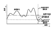
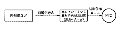
すなわち、このような応答遅れによってオーバーシュート、アンダーシュート、ハンチングなどの不具合が発生すると、冷却水系やエンジン部品の耐久性、燃費が悪化する等の問題が発生する。このような問題を解消するために、タイムラグ経過後の水温を予測する手段を設け、図7に示すようにタイムラグ経過後の予測した水温に合わせてバルブを先行制御することで、タイムラグを擬似的に解消するように構成するとよい。
【0045】
ここで、タイムラグ経過後を予測した水温とは、制御に使用される水温であって、この水温で先行制御すれば、タイムラグ経過後に必要とされるPTC通電を事前に通電でき、タイムラグ経過後にその通電が反映されることになる。
そのステップとしては、始めに、センサから取り込んだ水温と単位時間あたりの水温変化量からタイムラグ経過後予測水温を算出する。ここで、水温変化の変化を算出すれば、より精度を上げることも可能である。
次に、求めた予測水温を元の通電量を決めるPID制御等を行うとよい。これを図8に示す。
【0046】
なお、タイムラグ経過後の水温はタイムラグ時間Td(通電変更から水温フィードバックされるまでの時間)から予測する方法に加えて、さらにラジエータ出口側水温変化、エンジン負荷などを加えて、より高精度に検知するようにしてもよい。たとえば冷却水の流速がNeに比例することからバルブ開弁から水温変化までの時間の変化にNeをパラメータとして算出に使用してもよい。さらに、通電変化から水温フィードバックまでの時間を毎回計測し、この値を基にタイムラグ時間Tdを決めるとエレメントなどの経年劣化などにも対応することができる。また、ミキシングに水温センサを設け、通電からバルブが開くまでの時間を測定し、より高精度なタイムラグ検出手段を用いてもよい。
【0047】
上述した方法では、制御の基準となる水温を、算出したタイムラグ経過後水温に差し替えることでタイムラグキャンセルを実現しているが、次のように目標水温を差し替えることでも、同じ動作を実現することができる。
この目標水温Tsの差し替え手法を説明する。
すなわち、始めにセンサから取り込んだ水温変化からタイムラグ経過後水温を算出する。
そして、図9に示すように、この求めた水温変化を設定水温から減算し、この設定水温に追従するようにPID制御を行うとよい。ここで、オーバーシュートとアンダーシュートでは制御の流れが逆になることは理解されよう。
【0048】
また、機械的駆動部位におけるヒステリシスの補正は、次のような場合に行われる。
たとえばバルブ開閉時に構造上での機械的な駆動部位に生じるヒステリシスにより、開弁から閉弁、閉弁から開弁への切換時、あるいは通電を徐々に上げたり下げたりしても開弁量が変わらない領域(不感帯)がある。これは、上述したようなバルブの機械的な駆動部位が、固定側との関係において動き出すまでの間に時間がかかるからである。
そのため、このような領域の影響を受けないようにバルブが、「開弁から閉弁へ」、「閉弁から開弁へ」の切換時に、図10に例示したようにPTCへの出力(通電)を余分に加減(ベースアップおよびベースダウン)したりして補正するとよいのである。
【0049】
さらに、消費電力を抑える補正とは、設定水温と制御水温との温度差が一定値以下になったときに、PTCへの通電(アクチュエータへの通電等)を止めることで行われる。
すなわち、サーモスタットの開弁温度と同程度に設定温度をもってきた場合、PTCは常に通電される状態におかれ、消費電力が多くなり、燃費増大、出力低下を招く。したがって、図11に示すように、設定水温と制御水温の温度差ΔTがある値以下になったときはPTCへの通電を完全に止める。勿論、設定水温を上げて、結果通電量を減らす手法を用いてもよい。
【0050】
また、上述したWAX式サーモスタットに発熱装置を設置し、発熱装置には通電すると抵抗値が変化するもの(たとえば、PTCまたはニクロム線等)を使用した冷却水温制御を行うにあたっては、安全性の観点から、エンジン始動時にPTCまたはニクロム線等の抵抗値を測定することにより、基準範囲内にあるか否かによって、サーモスタットの故障判断を行うとよい。
【0051】
また、このような冷却水温制御を行うにあたって自動車全体のシステム面から見ると、エンジンに付随した補器類に連動した制御を行うことが望ましい。すなわち、PTCで多くの通電を必要とする場合には、連動してエアコンなどの補器類の作動をカットまたはオルタネータ等の通電を押さえる制御を加えることにより、補器類に連動させた制御を行うとよい。このようにすると、PTCへの消費電力が大きく、補器類も同時に作動させるようなとき等のようにかなりの電力を消費する場合において、燃料消費率、エンジン出力を確保することができる。
【0052】
また、上述した冷却水温制御を行うにあたっては、自動車を運転する運転者がエンジンの高負荷域を多用する人であるか、それとも低負荷域を多用する人かを判断し、設定水温を変化させることも、燃費低下、通電低下を防止するうえでは必要なことである。すなわち、従来の制御では、低負荷走行が多い運転者に設定水温を合わせると、設定水温が高くなるから、高負荷走行を多用する運転者にとっては燃費、エンジン出力とも悪化する。これは逆も同じである。
【0053】
このような不具合を解消するには、図12、図13に示すように、運転者によって設定水温を変化する制御を行うとよい。
すなわち、一定時間、運転者の負荷の変化をモニタリングし、負荷の平均を算出することで行う。たとえば、その負荷平均値が一定値以上であれば、高負荷多用運転者と判断し、設定水温を下げる。一方、負荷平均値が一定値以下であれば、低負荷多用運転者と判断し、設定水温を上げる。
【0054】
なお、上げ幅、下げ幅とも負荷平均値と比例させてもよい。また、設定水温とともに、高負荷判定基準を変更させ、低水温への移行を早めてもよい。さらに、アクセルの踏み方で判別してもよい。この設定水温をメモリしておき、次回のエンジン始動時にも同じ設定水温からスタートするような学習機能を持たせることも考えられる。
【0055】
また、上述した冷却水温制御を行うにあたっては、エレメントリフトの経年劣化の補正を行うことも望まれる。これは、エレメントの経年劣化により、水温制御性が初期に比べて低下することは避けられないからである。
このために、リフト劣化量を予測する手段を設け、その劣化量を補足するようにPTCへの通電を増大させるように制御し、これによりリフト劣化によるリフトダウン防止を実現するとよい。この状態を図14、図15、図16に示す。
【0056】
ここで、PTC通電量とリフト量の相関テーブルを用いて制御する場合は、これを考慮して補正量の算出を行うとよい。
また、エレメントリフト劣化検出にあたっては、始めにある運転条件下で、水温のオーバーシュート量の違い若しくは水温が上昇してから下降に転じた温度を初期状態と比較して、開弁温度のずれを検出し、リフト劣化量を導く。
次に、ある運転条件下、水温昇温時に、水温の傾斜が変化する温度を初期状態と比較して、開弁温度のずれを検出し、リフト劣化量を求めるとよい。
【0057】
また、上述した冷却水温制御を行うシステムでは、搭載する車両毎にサーモスタットのばらつき等により、PID(またはPI)制御定数をマッチングさせる必要がある。一般的には設計時に行うとよいが、エンジン冷却水系のばらつき、バルブのばらつき等を考慮して適切に制御するには煩雑さは避けられない。このため、エンジン組付け後に搭載される車両に応じてPI制御定数を自動的に決定し、自動チューニングを行えるようにすることが望ましい。
【0058】
すなわち、図17に示すように、一定時間の間、温度差の平均を算出し、これが小さくなるように比例定数、積分定数を増減させる。出荷時には適当な比例、積分定数を設定しておく。そして、ある時間の平均温度差ΔTを測定しておき、このときの比例、積分定数に対してそれぞれ定数を好ましくは1.5倍に増加させ、再度平均温度差を測定する。その際に、平均温度差が小さくなれば、その比例、積分定数をベースとして、さらに定数を好ましくは1.5倍にしてゆく。しかし、平均温度差が大きくなるようであれば、元の値を好ましくは0.65倍して平均温度差を測定し、温度差を小さくする。このとき、温度差が小さくならない場合は、元の値がベストの比例、積分定数と考えられるのである。
なお、サーモスタットの個体差や経年変化により最適な比例、積分定数は変化する場合も考えられるから、常に最適値を模索するように、この種の確認手段は動作していることが望ましい。
【0059】
なお、本発明は上述した実施の形態で説明した構造または数値には限定されず、各部の形状、構造等を適宜変形、変更し得ることはいうまでもない。
すなわち、本発明を適用する電子制御サーモスタットとしては、冷却水温を任意に温度制御できるものであればどのような構造のものでもよく、たとえばWAX+PTC式サーモスタット等といった電子制御サーモスタットであってもよい。また、発熱装置としても発熱素子に限られるものではなく、誘電加熱や誘導加熱やマイクロ波加熱を利用したもの及びニクロム線等の発熱体であればどのようなものでもよく、また発熱素子もPTCに限らずペルチェ素子等でもよい。さらに、WAXではなく、バイメタルや形状記憶合金(SMA)でもよい。
【0060】
また、その他の構成部品や冷却水循環路の構造、さらには各部で説明した数値などは図示や説明で特定されるものに限定されるものではなく、種々の形態のものを採用することは自由である。さらに、上述したそれぞれの制御での説明も、一例を例示したに過ぎず、本発明の精神を逸脱しない範囲において、種々の形態を採ることができる。
【0061】
【発明の効果】
以上説明したように本発明に係る電子制御サーモスタットの制御方法によれば、従来の制御での問題点を解消し、高精度で、低コスト、さらに高い冷却水温の追従性を実現することができる。
【0062】
また、本発明によれば、PTC通電回路を定電流回路としたことにより、発熱素子(たとえばPTC)の温度に左右されない発熱量を得ることができる。
さらに、本発明によれば、エンジン負荷判断手段、あるいは学習機能を持たせることにより、低コストでありながら、常にその自動車に適した設定水温を供給でき、最適燃費化、最適通電化を実現することができる。
【図面の簡単な説明】
【図1】 本発明に係る電子制御サーモスタット制御方法の一つの実施形態を示し、Rd流量センサを設けたシステムでの制御ブロック図である。
【図2】 本発明に係る電子制御サーモスタット制御方法を適用するエンジンの冷却水温度制御系を説明するための概略図である。
【図3】 図1の変形例を示す制御ブロック図である。
【図4】 図1、図3の変形例を示す制御ブロック図である。
【図5】 PTCの発熱回路を説明するための図である。
【図6】 エレメント放熱量補正制御を説明するための図である。
【図7】 応答遅れの補正制御を説明するためのグラフである。
【図8】 タイムラグ経過後予測水温のフィードバック制御を説明するための図である。
【図9】 図8の別の例を説明するための図である。
【図10】 機械的駆動部位におけるヒステリシスの補正制御を説明するためのグラフである。
【図11】 消費電力の低減制御を説明するためのグラフである。
【図12】 最適水温設定制御を説明するためのグラフである。
【図13】 (a),(b),(c)は設定水温を変えたことでの水温制御イメージを示すグラフである。
【図14】 エレメント経年劣化の補正制御を説明するための図である。
【図15】 エレメント経年劣化の補正制御を説明するためのグラフである。
【図16】 エレメントリフト劣化検出を説明するためのグラフである。
【図17】 PI値の学習制御を説明するためのグラフである。
【符号の説明】
1…エンジンとしての自動車用エンジン、2…熱交換器としてのラジエータ(Rd)、3…流出側冷却水路、4…流入側冷却水路、5…バイパス水路、10…水分配バルブとして機能する電子制御サーモスタットとしてのバルブユニット、11,12…水温センサ、20…制御装置(ECU:エンジンコントロールユニット)であるコントローラ、21…ラジエータ流量センサ(Rd流量センサ)、22…リフトセンサ、23…PTC温度センサ、24…WAX温度センサ。[0001]
BACKGROUND OF THE INVENTION
The present invention relates to an engine coolant temperature control system that variably sets a coolant temperature according to a load of an engine (hereinafter referred to as an engine) used in an automobile or the like.By installing a heating device such as a heating element in the temperature sensing part of the actuator,The present invention relates to a control method for an electronically controlled thermostat capable of arbitrarily changing a valve opening without depending only on an actual temperature.
[0002]
[Prior art]
In order to cool an automobile engine, a water-cooling type cooling device using a radiator is generally used. Conventionally, in this type of cooling device, for the purpose of improving the fuel efficiency of an automobile, a control valve, for example, a thermostat for adjusting the amount of cooling water to be circulated to the radiator side so as to control the temperature of cooling water introduced into the engine is provided. in use. As such a thermostat, one using a thermal expansion body as an actuator for controlling a valve, or one using electric control is known.
[0003]
In such a thermostat, the valve portion is interposed in a part of the cooling water passage, and when the cooling water temperature is low, the valve portion is closed and the cooling water is circulated through the bypass passage without passing through the radiator. When the cooling water temperature becomes high, the temperature of the cooling water can be controlled to a required state by opening the valve portion and circulating the cooling water through the radiator.
[0004]
By the way, it is generally known that the fuel efficiency of an automobile can be improved by lowering the coolant temperature when the engine of the automobile is operated at a high load and increasing the coolant temperature at a low load.
[0005]
Under such circumstances, electronically controlled valves, that is, electronically controlled thermostats have recently been increasingly employed to provide the optimum water temperature for improving the fuel efficiency of automobiles. Such an electronically controlled thermostat controls the cooling water temperature by arbitrarily controlling the opening degree of the valve portion and the cooling fan attached to the radiator, thereby appropriately adjusting the cooling water temperature. Can be controlled. This is because the control device (engine control module) that variably controls the electronic control thermostat described above detects various parameters in the engine control unit, such as cooling water temperature, outside air temperature, vehicle speed, engine speed, throttle opening, and the like. This is because the information can also be controlled.
[0006]
A number of various types have been proposed in the past for improving the fuel consumption by controlling the cooling water temperature in a required state.
For example, by installing a heating element in the temperature sensing part of the thermostat and using the heat generation control of this heating element together, electronic control has been made so that the cooling water can be immediately warmed up and the fuel efficiency of the engine can be improved when starting the engine. Thermostats have already been proposed (see, for example, Patent Document 1).
[0007]
[Patent Document 1]
JP 2001-317355 A
[0008]
[Problems to be solved by the invention]
By the way, in the electronic control thermostat as described above, what is a problem when controlling the cooling water temperature is “responsiveness from when the actuator is energized until the water temperature changes”.
[0009]
In other words, in the conventional electronic control thermostat control method, undershoot, overshoot, hunting, and heat of the cooling water are required during the period from when the actuator is energized until the valve opens and the actual cooling water temperature changes to the target water temperature. Various factors such as the speed of exchange affected and took a considerable amount of time.
[0010]
In addition, since the electric circuit for energizing the PTC as a heat generating device attached to the actuator has been a constant voltage circuit in the past, the resistance value of the PTC changes with temperature, so a certain amount of heat generation is ensured. I couldn't. For example, assuming that the temperature of the PTC is 0 ° C. and the energization is 10 W, the energization is 5 W when the temperature of the PTC is 100 ° C.
[0011]
In addition, for automobiles, it is difficult to determine the best set water temperature for the vehicle at the design stage, depending on how the driver rides, the layout of the cooling water circulation system for each vehicle, individual differences in the thermostat, etc. Therefore, it is desirable to consider this point.
[0012]
The present invention has been made in view of such circumstances, and it is an electronic device that can eliminate the above-mentioned problems that have been considered as problems, and can realize high cooling water temperature followability with high accuracy and low cost. An object is to obtain a control method of a control thermostat.
[0013]
Furthermore, the present invention provides an engine load determination means and a learning function, so that it is possible to always supply a set water temperature suitable for the vehicle at a low cost, thereby realizing optimum fuel consumption and optimum energization. The object is to obtain a control method of an electronically controlled thermostat.
[0014]
[Means for Solving the Problems]
In order to meet such an object, the control method of the electronically controlled thermostat according to the present invention (the invention described in claim 1) is used for engine coolant temperature control and does not depend only on the actual coolant temperature.Valve openingIn an electronically controlled thermostat having an actuator capable of arbitrarily changingThe actuator is a WAX type thermo element to which a heating device is attached,The controller is for operating the actuator.To the heating deviceIn addition to energizing, after energizingActuatorThe coolant temperature after the elapsed time is predicted by calculating the elapsed time until the temperature changes due to the operation and the amount of change in the water temperature per unit time, and the actuator is controlled according to the predicted water temperatureIn addition, it is configured to detect or calculate the difference between the actual flow rate of the cooling water and the target flow rate, and to correct the heat radiation amount of the thermo element and the hysteresis in the portion where the valve is driven.
In addition, in the other electronic control thermostat control, a control method capable of commonly handling various actuators used is obtained.
[0015]
Here, to control the actuator in advance means calculating the time until the set temperature is calculated and reaching the control water temperature, predicting the water temperature after the elapse of this time lag, and conducting the energization control ahead of the actuator according to the predicted water temperature. To activate the valve,Actuator heating deviceThis is a control that eliminates the response delay until the actual water temperature is reached after the energization of the battery is determined.
[0016]
Also actuatorIs a WAX type thermo element with a heat generating device installed in the temperature sensing partIt is.
[0017]
In this way, the response delay, which has been a problem in the past, can be eliminated by linearly controlling the valve so that the cooling water reaches the required temperature in a more realistic and required state. It is possible to achieve high cooling water temperature followability with high accuracy and low cost. This makes it possible to perform the cooling water temperature appropriately and efficiently according to the engine load in the driving state of the automobile, and is excellent in terms of responsiveness and cooling water temperature stability, overshoot, undershoot, hunting, etc. Therefore, it is possible to appropriately control the cooling water temperature at a high water temperature or a low water temperature, and further improve the fuel consumption more reliably and in almost the entire operating state.
[0018]
Moreover, according to the above-described configuration,By controlling the valve linearly in a required state that is even more realistic so that the cooling water becomes the required temperature, it is possible to eliminate the poor water temperature controllability that has been a problem in the past, With high accuracy and low cost, high cooling water temperature followability can be realized. This makes it possible to perform the cooling water temperature appropriately and efficiently according to the engine load in the driving state of the automobile, and is excellent in terms of responsiveness and cooling water temperature stability, overshoot, undershoot, hunting, etc. Therefore, it is possible to appropriately control the cooling water temperature at a high water temperature or a low water temperature, and further improve the fuel consumption more reliably and in almost the entire operating state.
[0019]
Here, the amount of heat dissipation of the element is the amount of heat released to predict the amount of heat released from the thermoelement to the cooling water and to ensure that the heat released by heat dissipation is absorbed by the expansion body (WAX). It is a correction that increases or decreases energization so that the corresponding heat can be compensated by the heating element, and eliminates the influence of heat dissipation. By performing such correction, it is possible to improve water temperature controllability such as hunting and water temperature control width.
[0020]
Further, correction of hysteresis in the mechanical drive part is performed in the following case.
For example, due to the hysteresis that occurs in the mechanical drive part of the structure when the valve is opened and closed, the valve opening amount can be reduced even when switching from valve opening to valve closing, from valve closing to valve opening, or when energization is gradually increased or decreased. There are areas that do not change. This is because it takes time until the mechanical drive portion of the valve as described above starts moving in relation to the fixed side. Therefore, in order to avoid the influence of such a region, the valve compensates by adding or subtracting power to the PTC at the time of switching from “open to close” or “from close to open”. is there.
[0021]
The present invention (Claim 2The control method of the electronically controlled thermostat according to the invention isClaim 1In the control controller,Actual flow rate of cooling water (radiator flow rate)By detecting parameters such as element lift, temperature of heating element, temperature of temperature sensor, etc.Actual flow rate of cooling water (radiator flow rate)It has the means to predict this.
[0022]
here,Actual flow rate of cooling water (radiator flow rate)The means for predicting is to feed back the element lift amount and calculate the target lift amount instead of the target flow rate when making the actuator determine energization. Alternatively, the target temperature is calculated instead of the target flow rate by feeding back the temperature of the heating element or the temperature of the temperature sensing element of the heating device.
[0023]
By doing this,Actual flow rate of cooling water (radiator flow rate)This makes it possible to control the cooling water temperature with high accuracy without sensing.
[0024]
The present invention (Claim 3The control method of the electronically controlled thermostat according to the
[0025]
By doing so, the response delay can be more appropriately eliminated, and the cooling water temperature can be controlled with high accuracy for a long time. Here, the correction that predicts the deterioration of the element lift amount means that the water temperature controllability becomes worse compared to the initial stage such that the water temperature hunting occurs or the water temperature control width increases due to the aging of the element. This is a correction that predicts the amount of lift deterioration from the difference from the overshoot increase amount and the initial water temperature gradient, and increases or decreases energization so as not to be affected by the amount of deterioration.
[0026]
The present invention (Claim 4The control method of the electronically controlled thermostat according to the invention isAny one of
In this way, the electronic control thermostat can be appropriately and reliably controlled.
[0027]
The automotive engine cooling water temperature control system including the electronic control thermostat to which the control method according to the present invention is applied as described above includes an electronic control thermostat having a structure capable of arbitrarily controlling the water temperature, and an actual water temperature in the cooling water system. (Actual water temperature) and a controller that includes a controller for performing correction calculation for controlling the cooling water to a set water temperature, a sensor for detecting the flow rate in the cooling water system, and a thermo A sensor for detecting the lift of the element, a WAX as an expansion body, a temperature sensor for detecting a heating element, or the like is appropriately used.
[0028]
DETAILED DESCRIPTION OF THE INVENTION
1 and 2 show an embodiment of a method for controlling an electronically controlled thermostat according to the present invention.
In these drawings, first, description will be given below based on FIG. 2 showing an outline of the entire cooling water temperature control system of an automobile engine including an electronic control thermostat.
[0029]
In FIG. 2,
2 is a heat exchanger, that is, a radiator (Rd), and a cooling water passage is formed in the
[0030]
This cooling water channel is provided at the outflow side cooling
[0031]
The
In addition, in locations where the thermoelement is not in contact with the cooling waterHeating element as a heating deviceHowever, when the heating element is energized, the valve can be controlled by the output signal from the controller according to the engine operating status, for example, when the coolant temperature rises when the engine load increases. It is possible to control the engine itself, such as opening the valve quickly or cooling the engine by increasing the lift amount than usual, and it is possible to arbitrarily change the valve opening degree without depending on only the actual temperature. .
In addition, although there exist things, such as a nichrome heater, a PTC element, a Peltier element, as a heat generating element, it can select according to a use.
The engine cooling water circulation path is formed by the
[0032]
A
[0033]
In the cooling water passage 4 on the inflow side, a
The
Although not shown in detail, the
[0034]
In the above configuration, the
According to the present invention, in the above-described cooling water temperature control system, the coolant flow rate sensor (hereinafter referred to as Rd flow rate sensor) 21 is provided in the inflow-side cooling water passage 4 from the
[0035]
That is, in the conventional structure, when performing the water temperature control of the cooling water, the PID (or PI) control is performed based on the temperature difference in the cooling
[0036]
FIG. 1 is a control block diagram in a system in which a conventional thermostat is provided with a heat generating device and an
[0037]
Instead of the Rd flow sensor, an element lift that easily predicts the Rd flow, and temperatures of the PTC and WAX that are the heat generating devices may be used, and this may be used as another feedback information.
That is, when the
[0038]
FIG. 3 shows a case where the above-described
FIG. 4 shows a case in which the
By doing so, it is possible to eliminate the radiator flow rate sensor without sensing the radiator flow rate.
In FIG. 1, FIG. 3, and FIG. 4 described above, in each correction control, the PID calculation result is added / subtracted / divided, but instead, the PID control constant may be changed.
[0039]
When the temperature control of the cooling water is performed in the steps as described above, when a PTC is used as a heating element, a constant current circuit may be used as a heating circuit for energizing the PTC. That is, in the case where a PTC and a WAX element (bimetal or shape memory alloy SMA) are combined with an actuator heating device in an electronically controlled thermostat (valve unit 10), the WAX element is heated with PTC and the valve is opened. In the structure, it is ideal that the amount of heat generated by the PTC can be kept constant in order to maintain the valve opening amount.
[0040]
However, since a constant voltage circuit is conventionally used for this PTC energization circuit, even if the same voltage is applied, the energization also changes because the resistance changes due to the temperature rise of the PTC itself, and the valve opening amount fluctuates. , Water temperature hunting, water temperature control width is increased and water temperature controllability is deteriorated.
In order to eliminate such a point, by using a constant current circuit in the PTC energization circuit as shown in FIG. 5 and canceling the energization change characteristic due to the temperature change of the PTC itself, stable energization can be secured, and PTC heat generation is achieved. The amount can be easily controlled.
[0041]
In the control block diagram of FIG. 1 or FIG. 3 and FIG. 4 described above, the heat radiation amount correction of the element predicts the heat radiation amount from the thermo element to the cooling water, and ensures the heat that escapes from the heat radiation. In order to absorb the expansion body (WAX), the current is increased / decreased so that the heat corresponding to the heat radiation amount can be compensated by the PTC, thereby eliminating the influence of the heat radiation.
[0042]
That is, when the element heated by the PTC is disposed in the cooling water or is disposed at a position where a part of the element is in contact with the cooling water, the generated heat is always radiated to the cooling water flowing around. When this heat dissipation amount increases, the valve opening amount cannot be maintained even if the same energization is applied to the PTC, resulting in poor water temperature controllability. In order to solve this, as shown in FIG. 6, a means for predicting the amount of heat released from the element to the cooling water is provided, and the energization is increased or decreased so that the heat corresponding to the amount of heat released is supplemented by the PTC. As a result, even if the amount of heat radiated from the element to the cooling water increases or decreases, the influence on the valve closing amount can be eliminated.
[0043]
In this element heat radiation correction control, the heat radiation amount required at that time is extracted from the element heat radiation correction amount map for Ne and added to PTC energization. In addition to the method of simply predicting from Ne, the element heat radiation amount may be predicted with higher accuracy using Ne, control water temperature, outside air temperature, radiator outlet water temperature, engine load, and the like. .
[0044]
The response delay canceling control is performed as follows.
That is, when a problem such as overshoot, undershoot, and hunting occurs due to such a response delay, problems such as deterioration of the durability of the cooling water system and engine parts and fuel consumption occur. In order to solve such a problem, a means for predicting the water temperature after the time lag elapses is provided, and the valve is controlled in advance according to the predicted water temperature after the time lag elapses as shown in FIG. It may be configured to eliminate the problem.
[0045]
Here, the water temperature predicted after the elapse of the time lag is the water temperature used for the control, and if the preceding control is performed at this water temperature, the PTC energization required after the elapse of the time lag can be energized in advance, and after the elapse of the time lag, Energization is reflected.
As the step, first, the predicted water temperature after the lapse of time lag is calculated from the water temperature taken from the sensor and the water temperature change amount per unit time. Here, if the change in the water temperature change is calculated, the accuracy can be further increased.
Next, it is good to perform PID control etc. which determine the original energization amount for the calculated predicted water temperature. This is shown in FIG.
[0046]
In addition to the method of predicting the water temperature after the time lag has elapsed from the time lag time Td (the time from when the power is changed until the water temperature is fed back), the water temperature change at the outlet side of the radiator, engine load, etc. are added to detect the water temperature with higher accuracy. You may make it do. For example, since the flow rate of the cooling water is proportional to Ne, Ne may be used for calculation as a parameter for the change in time from the valve opening to the water temperature change. Furthermore, when the time from energization change to water temperature feedback is measured every time, and the time lag time Td is determined based on this value, it is possible to cope with aging deterioration of elements and the like. Further, a water temperature sensor may be provided for mixing, and the time from energization to opening of the valve may be measured, and more accurate time lag detection means may be used.
[0047]
In the method described above, the time lag cancellation is realized by replacing the water temperature that is the reference for control with the water temperature after the lapse of the calculated time lag, but the same operation can also be realized by replacing the target water temperature as follows. it can.
A method for replacing the target water temperature Ts will be described.
That is, the water temperature is calculated after the lapse of time from the change in the water temperature first taken from the sensor.
And as shown in FIG. 9, it is good to subtract this calculated | required water temperature change from setting water temperature, and to perform PID control so that this setting water temperature may be tracked. Here, it will be understood that the flow of control is reversed between overshoot and undershoot.
[0048]
Further, correction of hysteresis in the mechanical drive part is performed in the following case.
For example, due to the hysteresis that occurs in the mechanical drive part of the structure when the valve is opened and closed, the valve opening amount can be reduced even when switching from valve opening to valve closing, from valve closing to valve opening, or when the energization is gradually increased or decreased. There is an area that does not change (dead zone). This is because it takes time until the mechanical drive portion of the valve as described above starts moving in relation to the fixed side.
Therefore, in order to avoid the influence of such a region, when the valve is switched from “open to close” or “from close to open”, the output (energization) to the PTC as illustrated in FIG. ) Is added and subtracted (base up and base down)It's good.
[0049]
Further, the correction for reducing the power consumption is performed by stopping energization of the PTC (such as energization of the actuator) when the temperature difference between the set water temperature and the control water temperature becomes a certain value or less.
That is, when the set temperature reaches the same level as the valve opening temperature of the thermostat, the PTC is always energized, power consumption increases, and fuel consumption increases and output decreases. Therefore, as shown in FIG. 11, when the temperature difference ΔT between the set water temperature and the control water temperature falls below a certain value, the energization to the PTC is completely stopped. Of course, a method of increasing the set water temperature and reducing the energization amount as a result may be used.
[0050]
In addition, when a heating device is installed in the above-described WAX thermostat, and the cooling water temperature control is performed using a device whose resistance value changes when the heating device is energized (for example, PTC or nichrome wire), a safety point of view. Therefore, it is preferable to determine the failure of the thermostat by measuring the resistance value of PTC or nichrome wire at the time of starting the engine, depending on whether or not it is within the reference range.
[0051]
Further, when performing such cooling water temperature control, it is desirable to perform control in conjunction with auxiliary devices attached to the engine from the viewpoint of the system of the entire automobile. In other words, when a large amount of electricity is required in the PTC, the operation linked to the auxiliary devices is controlled by adding the control that cuts off the operation of the auxiliary devices such as the air conditioner or suppresses the electricity supply such as the alternator. It is good to do. In this way, the fuel consumption rate and the engine output can be ensured when the power consumption to the PTC is large and a considerable amount of power is consumed, such as when the auxiliary devices are operated simultaneously.
[0052]
Further, when performing the above-described cooling water temperature control, it is determined whether the driver driving the automobile is a person who heavily uses the high load area of the engine or a person who frequently uses the low load area, and changes the set water temperature. This is also necessary to prevent a reduction in fuel consumption and a decrease in energization. That is, in the conventional control, when the set water temperature is adjusted to a driver who frequently travels with a low load, the set water temperature becomes high. Therefore, for a driver who frequently uses a high load, both fuel consumption and engine output are deteriorated. The reverse is also true.
[0053]
In order to eliminate such a problem, as shown in FIGS. 12 and 13, it is preferable to perform control to change the set water temperature by the driver.
That is, it is performed by monitoring the change of the driver's load for a certain period of time and calculating the average of the load.For example,If the load average value is equal to or greater than a certain value, it is determined that the driver is a heavy load heavy driver and the set water temperature is lowered. On the other hand, if the load average value is below a certain value, it is determined that the driver is a low load heavy driver and the set water temperature is raised.
[0054]
It should be noted that both the increase range and the decrease range may be proportional to the load average value. In addition, the high load determination criterion may be changed together with the set water temperature to speed up the transition to the low water temperature. Further, the determination may be made based on how the accelerator is depressed. It is also conceivable to store this set water temperature and to have a learning function that starts from the same set water temperature at the next engine start.
[0055]
Further, in performing the above-described cooling water temperature control, it is also desired to correct the element lift over time. This is because it is unavoidable that the water temperature controllability is deteriorated compared to the initial stage due to aging of the element.
For this purpose, it is preferable to provide means for predicting the amount of lift deterioration, and to control the energization of the PTC so as to supplement the amount of deterioration, thereby realizing prevention of lift-down due to lift deterioration. This state is shown in FIG. 14, FIG. 15, and FIG.
[0056]
Here, when the control is performed using the correlation table between the PTC energization amount and the lift amount, the correction amount may be calculated in consideration of this.
In addition, when detecting element lift deterioration, the difference in the overshoot amount of the water temperature or the temperature at which the water temperature started to decrease under the initial operating conditions is compared with the initial state, and the deviation in the valve opening temperature is detected. Detects the amount of lift deterioration.
Next, when the temperature of the water temperature is raised under certain operating conditions, the temperature at which the slope of the water temperature changes is compared with the initial state to detect a deviation in the valve opening temperature and obtain the lift deterioration amount.
[0057]
Further, in the system that performs the cooling water temperature control described above, it is necessary to match PID (or PI) control constants due to variations in the thermostat for each vehicle to be mounted. Generally, it is good to carry out at the time of design, but complicatedness is unavoidable for appropriate control in consideration of variations in engine cooling water systems, valve variations, and the like. For this reason, it is desirable that the PI control constant is automatically determined according to the vehicle mounted after assembly of the engine so that automatic tuning can be performed.
[0058]
That is,As shown in FIG. 17, the average of the temperature difference is calculated for a certain period of time, and the proportionality constant and the integration constant are increased or decreased so as to decrease the average. Appropriate proportionality and integral constants are set at the time of shipment. Then, an average temperature difference ΔT for a certain time is measured, and the constant is preferably increased by 1.5 times with respect to the proportionality and integral constants at this time, and the average temperature difference is measured again. At that time, if the average temperature difference becomes small, the constant is preferably increased by a factor of 1.5 based on the proportionality and integral constant. However, if the average temperature difference becomes large, the original value is preferably multiplied by 0.65, the average temperature difference is measured, and the temperature difference is reduced. At this time, if the temperature difference does not become small, the original value is considered to be the best proportionality and integration constant.
It should be noted that the optimal proportionality and integral constant may change due to individual differences in thermostats and changes over time. Therefore, it is desirable that this type of confirmation means operate so as to always search for the optimal value.
[0059]
Note that the present invention is not limited to the structures or numerical values described in the above-described embodiments, and it goes without saying that the shape and structure of each part can be appropriately modified and changed.
That is, the electronic control thermostat to which the present invention is applied may have any structure as long as the cooling water temperature can be arbitrarily controlled. For example, a WAX + PTC type thermostat.Etc.An electronically controlled thermostat may be used. Further, the heating device is not limited to a heating element, and any heating element using dielectric heating, induction heating, microwave heating, or a heating element such as a nichrome wire may be used. However, it is not limited to Peltier elements. Furthermore, instead of WAX, bimetal or shape memory alloy (SMA) may be used.
[0060]
Further, the other components, the structure of the cooling water circulation path, and the numerical values explained in each part are not limited to those specified in the drawings and explanations, and various forms can be freely adopted. is there. Furthermore, the description of each control described above is merely an example, and various forms can be adopted without departing from the spirit of the present invention.
[0061]
【The invention's effect】
As described above, according to the control method of the electronically controlled thermostat according to the present invention, problems in conventional control can be solved, and high accuracy, low cost, and high followability of the cooling water temperature can be realized. .
[0062]
Further, according to the present invention, since the PTC energization circuit is a constant current circuit, it is possible to obtain a heat generation amount that is not influenced by the temperature of the heat generating element (for example, PTC).
Furthermore, according to the present invention, by providing an engine load determination means or a learning function, it is possible to always supply a set water temperature suitable for the automobile at a low cost, thereby realizing optimum fuel consumption and optimum energization. be able to.
[Brief description of the drawings]
FIG. 1 is a control block diagram of a system provided with an Rd flow sensor according to an embodiment of an electronically controlled thermostat control method according to the present invention.
FIG. 2 is a schematic diagram for explaining an engine coolant temperature control system to which an electronically controlled thermostat control method according to the present invention is applied.
FIG. 3 is a control block diagram showing a modification of FIG. 1;
4 is a control block diagram showing a modification of FIGS. 1 and 3. FIG.
FIG. 5 is a diagram for explaining a heat generation circuit of a PTC.
FIG. 6 is a diagram for explaining element heat radiation amount correction control;
FIG. 7 is a graph for explaining response delay correction control;
FIG. 8 is a diagram for explaining feedback control of a predicted water temperature after the time lag has elapsed.
FIG. 9 is a diagram for explaining another example of FIG. 8;
FIG. 10 is a graph for explaining hysteresis correction control in a mechanical drive portion;
FIG. 11 is a graph for explaining power consumption reduction control;
FIG. 12 is a graph for explaining optimum water temperature setting control.
FIGS. 13A, 13B, and 13C are graphs showing water temperature control images when the set water temperature is changed.
FIG. 14 is a view for explaining correction control for element aging.
FIG. 15 is a graph for explaining correction control for element aging.
FIG. 16 is a graph for explaining element lift deterioration detection;
FIG. 17 is a graph for explaining PI value learning control;
[Explanation of symbols]
DESCRIPTION OF
Claims (4)
前記アクチュエータは、発熱装置を取付けたWAX式サーモエレメントであって、
制御コントローラは、前記アクチュエータを作動させるための前記発熱装置への通電を行うのと併せて、
通電後から前記アクチュエータが作動して温度変化するまでの経過時間と単位時間あたりの水温変化量を算出することで、前記経過時間後の冷却水温度を予測し、
前記予測水温に合わせて前記アクチュエータを制御するとともに、
冷却水の実際の流量と目標流量との差を検出または算出し、
サーモエレメントの放熱量と前記バルブの駆動する部位におけるヒステリシスを補正するように構成されていることを特徴とする電子制御サーモスタットの制御方法。In an electronically controlled thermostat equipped with an actuator that can be used to control the coolant temperature of an engine and can arbitrarily change the opening of a valve without depending only on the actual coolant temperature,
The actuator is a WAX type thermo element to which a heating device is attached,
In addition to energizing the heat generating device for operating the actuator,
By calculating the elapsed time from the time of energization until the temperature of the actuator is changed and the temperature change per unit time, the coolant temperature after the elapsed time is predicted,
While controlling the actuator according to the predicted water temperature ,
Detect or calculate the difference between the actual cooling water flow rate and the target flow rate,
A control method for an electronically controlled thermostat, characterized in that the heat dissipation amount of the thermo element and the hysteresis at a portion driven by the valve are corrected .
前記制御コントローラは、冷却水の実際の流量以外のエレメントリフト量、発熱体の温度、感温体の温度等のパラメータを検出することにより冷却水の実際の流量を予測する手段を有することを特徴とする電子制御サーモスタットの制御方法。 The method of controlling an electronically controlled thermostat according to claim 1 ,
The controller has means for predicting the actual flow rate of the cooling water by detecting parameters such as the element lift amount, the temperature of the heating element, and the temperature of the temperature sensing element other than the actual flow rate of the cooling water. A method for controlling an electronically controlled thermostat.
前記制御コントローラは、エレメントリフト量の劣化量を予測することで前記エレメントリフトを補正する制御を備えることを特徴とする電子制御サーモスタットの制御方法。 In the control method of the electronically controlled thermostat according to claim 1 or 2 ,
The method of controlling an electronically controlled thermostat, wherein the control controller includes control for correcting the element lift by predicting a deterioration amount of the element lift.
前記制御コントローラは、前記エンジンの始動時には、前記発熱装置の抵抗値を測定することで、前記抵抗値と前もって格納していた基準抵抗値との差が所定値以上になった場合に前記電子制御サーモスタットが故障したと判断することを特徴とする電子制御サーモスタットの制御方法。 In the control method of the electronically controlled thermostat according to any one of claims 1 to 3 ,
The control controller measures the resistance value of the heat generating device at the time of starting the engine, and the electronic control is performed when a difference between the resistance value and a reference resistance value stored in advance becomes a predetermined value or more. A control method for an electronically controlled thermostat, characterized in that it is determined that the thermostat has failed.
Priority Applications (4)
| Application Number | Priority Date | Filing Date | Title |
|---|---|---|---|
| JP2002304033A JP3932277B2 (en) | 2002-10-18 | 2002-10-18 | Control method of electronic control thermostat |
| US10/496,016 US7320434B2 (en) | 2002-10-18 | 2003-08-26 | Method of controlling electronic controlled thermostat |
| DE10392219.9T DE10392219B4 (en) | 2002-10-18 | 2003-08-26 | Control method with electronically controlled thermostat |
| PCT/JP2003/010808 WO2004036007A1 (en) | 2002-10-18 | 2003-08-26 | Method of controlling electronic controlled thermostat |
Applications Claiming Priority (1)
| Application Number | Priority Date | Filing Date | Title |
|---|---|---|---|
| JP2002304033A JP3932277B2 (en) | 2002-10-18 | 2002-10-18 | Control method of electronic control thermostat |
Publications (2)
| Publication Number | Publication Date |
|---|---|
| JP2004137981A JP2004137981A (en) | 2004-05-13 |
| JP3932277B2 true JP3932277B2 (en) | 2007-06-20 |
Family
ID=32105097
Family Applications (1)
| Application Number | Title | Priority Date | Filing Date |
|---|---|---|---|
| JP2002304033A Expired - Fee Related JP3932277B2 (en) | 2002-10-18 | 2002-10-18 | Control method of electronic control thermostat |
Country Status (4)
| Country | Link |
|---|---|
| US (1) | US7320434B2 (en) |
| JP (1) | JP3932277B2 (en) |
| DE (1) | DE10392219B4 (en) |
| WO (1) | WO2004036007A1 (en) |
Families Citing this family (65)
| Publication number | Priority date | Publication date | Assignee | Title |
|---|---|---|---|---|
| DE10336599B4 (en) * | 2003-08-08 | 2016-08-04 | Daimler Ag | Method for controlling a thermostat in a cooling circuit of an internal combustion engine |
| SE528778C2 (en) | 2005-03-30 | 2007-02-13 | Scania Cv Ab | A method and a control unit for determining the opening temperature of a temperature controller |
| JP4821247B2 (en) * | 2005-10-06 | 2011-11-24 | トヨタ自動車株式会社 | Cooling water control device for internal combustion engine |
| US8316926B2 (en) | 2005-10-31 | 2012-11-27 | General Cybernation Group Inc. | Arrangement and method for automatically determined time constant for a control device |
| JP2008025764A (en) * | 2006-07-24 | 2008-02-07 | Nitta Ind Corp | Thermal expansion polymer wax actuator |
| JP5050516B2 (en) * | 2006-12-11 | 2012-10-17 | パナソニック株式会社 | Sauna equipment |
| JP2009146241A (en) * | 2007-12-17 | 2009-07-02 | Fuji Koki Corp | Valve control device and valve control method |
| DE102008030969A1 (en) * | 2008-06-30 | 2009-12-31 | Agco Gmbh | Flow Control |
| US20120004172A1 (en) * | 2008-10-27 | 2012-01-05 | Oncotherapy Science, Inc. | Screening method of anti-lung or esophageal cancer compounds |
| US8215381B2 (en) * | 2009-04-10 | 2012-07-10 | Ford Global Technologies, Llc | Method for controlling heat exchanger fluid flow |
| JP4860746B2 (en) * | 2009-11-24 | 2012-01-25 | アイシン精機株式会社 | Engine cooling system |
| EP2447498B1 (en) * | 2009-12-04 | 2014-03-26 | Toyota Jidosha Kabushiki Kaisha | Control device for vehicle |
| WO2011089705A1 (en) * | 2010-01-22 | 2011-07-28 | トヨタ自動車 株式会社 | Cooling device for vehicle |
| JP5500264B2 (en) * | 2010-11-01 | 2014-05-21 | トヨタ自動車株式会社 | Internal combustion engine cooling system |
| DE102011003430B3 (en) * | 2011-02-01 | 2012-05-31 | Continental Automotive Gmbh | Method and device for checking a control device |
| JP5168379B2 (en) * | 2011-03-28 | 2013-03-21 | トヨタ自動車株式会社 | Cooling water control device for internal combustion engine |
| JP5618945B2 (en) * | 2011-08-22 | 2014-11-05 | 日立オートモティブシステムズ株式会社 | Cooling control device for internal combustion engine |
| GB201119371D0 (en) * | 2011-11-10 | 2011-12-21 | Ford Global Tech Llc | A method for improving warm-up of an engine |
| KR101875621B1 (en) | 2012-04-09 | 2018-07-06 | 현대자동차 주식회사 | Glow plug and electric thermostat with the same |
| US9719407B2 (en) | 2012-08-03 | 2017-08-01 | Ford Global Technologies, Llc | Method for regulating engine temperature |
| JP2014101767A (en) * | 2012-11-16 | 2014-06-05 | Toyota Motor Corp | Cooling control device |
| JP2014101876A (en) * | 2012-11-20 | 2014-06-05 | Hyundai Motor Company Co Ltd | Engine system including thermostat |
| US20150369113A1 (en) * | 2013-01-30 | 2015-12-24 | Fishman Thermo Technologies Ltd | Hydro-actuated thermostats |
| JP6301061B2 (en) | 2013-02-18 | 2018-03-28 | 株式会社ミクニ | Valve control device and valve control method |
| FR3010446B1 (en) * | 2013-09-12 | 2015-10-02 | Peugeot Citroen Automobiles Sa | METHOD FOR CONTROLLING COOLANT TEMPERATURE TEMPERATURE FOR MOTOR VEHICLE |
| KR101526419B1 (en) * | 2013-12-16 | 2015-06-11 | 현대자동차 주식회사 | Method and system for diagnosting system for cooling power electronic components of hybrid vehicle |
| US10865697B2 (en) * | 2014-01-15 | 2020-12-15 | Renault S.A.S. | Thermostat device for motor vehicle cooling system, cooling system equipped with such a thermostat device and method of controlling a heating module |
| FR3016397B1 (en) * | 2014-01-15 | 2016-02-05 | Renault Sas | THERMOSTAT DEVICE FOR AUTOMOTIVE VEHICLE COOLING SYSTEM, COOLING SYSTEM EQUIPPED WITH SUCH A THERMOSTAT DEVICE AND METHOD OF CONTROLLING A HEATING MODULE |
| FR3016400B1 (en) * | 2014-01-15 | 2016-02-05 | Renault Sas | METHOD FOR ESTIMATING A COOLANT TEMPERATURE AND COOLING SYSTEM FOR A MOTOR VEHICLE DRIVE MOTOR |
| DE102014201170A1 (en) * | 2014-01-23 | 2015-07-23 | Bayerische Motoren Werke Aktiengesellschaft | Method and device for venting a thermal management system of an internal combustion engine |
| DE102014016307A1 (en) * | 2014-11-06 | 2016-05-12 | Man Truck & Bus Ag | Device for monitoring an oil thermostat |
| DE102014117391A1 (en) * | 2014-11-27 | 2016-06-02 | Elka-Elektronik Gmbh | Method for controlling a state variable that can be regulated by a building-technical installation |
| US10221755B2 (en) * | 2014-12-27 | 2019-03-05 | Marcus A. Garraway | Thermal controller with automotive applications |
| US9840962B2 (en) * | 2015-06-25 | 2017-12-12 | GM Global Technology Operations LLC | System and method for controlling inlet coolant temperature of an internal combustion engine |
| JP6487313B2 (en) * | 2015-11-27 | 2019-03-20 | 株式会社アドヴィックス | Valve control device, hydraulic pressure control device, and valve control method |
| KR101720568B1 (en) | 2016-05-04 | 2017-03-29 | 엔브이에이치코리아(주) | flow control valve of combine type |
| EP3242061B1 (en) | 2016-05-04 | 2019-03-06 | Hyundai Motor Company | Coolant control valve unit having sealing structure |
| KR102518247B1 (en) | 2016-07-18 | 2023-04-07 | 현대자동차주식회사 | Control method for flow control valve |
| FR3054282B1 (en) * | 2016-07-21 | 2018-08-31 | Vernet | MIXING UNIT AND MIXER TAP COMPRISING SUCH A MIXING UNIT |
| US10494984B2 (en) * | 2016-09-15 | 2019-12-03 | Ford Global Technologies, Llc | Method and system for monitoring cooling system |
| DE102016124675A1 (en) * | 2016-12-12 | 2018-06-14 | Illinois Tool Works Inc. | Thermostatic valve for an internal combustion engine |
| JP6461221B2 (en) * | 2017-03-30 | 2019-01-30 | 株式会社Subaru | Engine control device |
| US10190478B1 (en) * | 2017-07-25 | 2019-01-29 | GM Global Technology Operations LLC | Controlling a cooling system for an internal combustion engine using feedback linearization |
| KR102371717B1 (en) | 2017-08-17 | 2022-03-08 | 현대자동차주식회사 | Flow control valve |
| EP3444461B1 (en) * | 2017-08-18 | 2020-03-11 | Meccanotecnica Umbra S.p.A. | Thermostat for cooling system of an internal combustion engine for vehicles |
| KR102391010B1 (en) | 2017-10-18 | 2022-04-27 | 현대자동차주식회사 | Fail-safe controlled method for cooling system of vehicles |
| KR102398887B1 (en) | 2017-10-25 | 2022-05-18 | 현대자동차주식회사 | Cooling system for vehicles and thereof controlled method |
| KR102478089B1 (en) | 2017-11-07 | 2022-12-16 | 현대자동차주식회사 | Cooling system for vehicles and thereof controlled method |
| JP2019089524A (en) * | 2017-11-17 | 2019-06-13 | アイシン精機株式会社 | Vehicular heat exchange device |
| KR102496255B1 (en) | 2017-12-11 | 2023-02-08 | 현대자동차주식회사 | Flow control valve |
| KR102019321B1 (en) | 2017-12-19 | 2019-09-09 | 현대자동차(주) | Controlled method for flow control valve |
| KR102478096B1 (en) | 2017-12-19 | 2022-12-19 | 현대자동차주식회사 | Flow control valve |
| KR102452470B1 (en) | 2018-05-15 | 2022-10-11 | 현대자동차주식회사 | Fault diagnosis method of coolant temperature sensor for vehicles |
| KR102075137B1 (en) | 2018-09-03 | 2020-02-10 | 현대자동차(주) | Method for controlled cooling system of vehicles |
| KR102132030B1 (en) | 2018-10-10 | 2020-07-09 | 현대자동차(주) | Method for controlled cooling system of vehicles |
| FR3087488B1 (en) * | 2018-10-23 | 2020-12-18 | Psa Automobiles Sa | PROCESS FOR EARLY OPENING OF A COLD THERMOSTAT IN AN ENGINE COOLING SYSTEM |
| FR3088677B1 (en) * | 2018-11-20 | 2020-11-13 | Psa Automobiles Sa | METHOD AND DEVICE FOR COOLING AN INTERNAL COMBUSTION ENGINE |
| CN111335999B (en) * | 2018-12-18 | 2021-02-05 | 广州汽车集团股份有限公司 | Control method and device of electric heating thermostat and electronic control unit |
| KR20200138482A (en) | 2019-05-29 | 2020-12-10 | 현대자동차주식회사 | Method and system for diagnosing failure of integrated thermal management valve |
| CN112746891A (en) * | 2019-10-31 | 2021-05-04 | 日立汽车系统(苏州)有限公司 | Engine coolant control system and engine coolant control method |
| KR102373426B1 (en) | 2020-03-27 | 2022-03-14 | 주식회사 엔티엠 | Flow control valve |
| JP7444740B2 (en) | 2020-09-07 | 2024-03-06 | 株式会社ミクニ | engine cooling system |
| CN112084661B (en) * | 2020-09-10 | 2022-07-05 | 中国船舶重工集团海装风电股份有限公司 | Wind turbine converter water cooling system cooling state assessment early warning method |
| CN112630526B (en) * | 2020-12-17 | 2024-04-05 | 北京航天计量测试技术研究所 | Improved flow type microwave medium power measuring device and measuring method |
| CN113446105B (en) * | 2021-06-10 | 2022-09-06 | 深圳市永亿豪电子有限公司 | Vehicle-mounted efficient fan control method and device, computer equipment and storage medium |
Family Cites Families (24)
| Publication number | Priority date | Publication date | Assignee | Title |
|---|---|---|---|---|
| JPS5837376A (en) * | 1981-08-31 | 1983-03-04 | Akira Sasaki | Thermo responsive pressure control valve |
| DE3244603C1 (en) * | 1982-12-02 | 1984-06-28 | Dieter Gräßlin Feinwerktechnik, 7742 St Georgen | Device for thermostatic valves, in particular for lowering the temperature of thermostatically controlled radiators |
| EP0557113B1 (en) * | 1992-02-19 | 1999-05-26 | Honda Giken Kogyo Kabushiki Kaisha | Engine cooling system |
| US5404842A (en) * | 1992-12-15 | 1995-04-11 | Nippon Soken, Inc. | Internal combustion engine cooling apparatus |
| DE4328719A1 (en) * | 1993-08-26 | 1995-03-02 | Bosch Gmbh Robert | Method for monitoring at least one electrical consumer |
| DE19519378B4 (en) * | 1995-05-26 | 2011-06-30 | Bayerische Motoren Werke Aktiengesellschaft, 80809 | Cooling system with electrically adjustable actuator |
| JPH108960A (en) | 1996-06-27 | 1998-01-13 | Mitsubishi Motors Corp | Cooling fan device for vehicle |
| US6152376A (en) * | 1997-02-21 | 2000-11-28 | Heat-Timer Corporation | Valve modulation method and system utilizing same |
| JP3859307B2 (en) * | 1997-05-16 | 2006-12-20 | 日本サーモスタット株式会社 | Cooling control device for internal combustion engine |
| JP3891512B2 (en) * | 1997-05-29 | 2007-03-14 | 日本サーモスタット株式会社 | Cooling control device and cooling control method for internal combustion engine |
| JP3266851B2 (en) * | 1998-04-01 | 2002-03-18 | 日本サーモスタット株式会社 | Cooling control device for internal combustion engine |
| JP3838528B2 (en) | 1997-07-02 | 2006-10-25 | 日本サーモスタット株式会社 | Cooling control device and cooling control method for internal combustion engine |
| EP0889211B1 (en) * | 1997-07-02 | 2006-09-13 | Nippon Thermostat Co., Ltd. | Cooling control system and cooling control method for engine |
| JP3644262B2 (en) | 1998-07-29 | 2005-04-27 | 株式会社デンソー | Cooling device for liquid-cooled internal combustion engine |
| DE19960079A1 (en) * | 1998-12-15 | 2000-06-21 | Bosch Gmbh Robert | Procedure for switching loads by switch elements that can be controlled by control unit has switching priorities assigned to loads changed dynamically during operation and changed according to operating state of loads |
| JP2000303842A (en) * | 1999-04-21 | 2000-10-31 | Honda Motor Co Ltd | Cooling control device for engine |
| JP2001032714A (en) | 1999-07-23 | 2001-02-06 | Honda Motor Co Ltd | Cooling control device for engine |
| DE19951362A1 (en) * | 1999-10-26 | 2001-05-03 | Bosch Gmbh Robert | Method for regulating the cooling water temperature of a motor vehicle with an internal combustion engine |
| JP4192386B2 (en) | 2000-03-02 | 2008-12-10 | 株式会社島津製作所 | Furnace atomic absorption spectrophotometer |
| JP4187131B2 (en) * | 2000-04-28 | 2008-11-26 | 日本サーモスタット株式会社 | Thermostat device |
| FR2811709B1 (en) * | 2000-07-17 | 2003-02-21 | Vernet Sa | PROPORTIONAL CONTROL PILOT THERMOSTATIC DEVICE, WITH SAFETY THERMOSTATIC ELEMENT |
| JP3680727B2 (en) | 2000-11-24 | 2005-08-10 | トヨタ自動車株式会社 | Exhaust gas purification device for internal combustion engine |
| JP3915966B2 (en) * | 2001-10-15 | 2007-05-16 | 日本サーモスタット株式会社 | Control method of electronic control thermostat |
| KR100521913B1 (en) * | 2002-02-09 | 2005-10-13 | 현대자동차주식회사 | CONTROL METHOD OF Adjustable Electronic Thermostat |
-
2002
- 2002-10-18 JP JP2002304033A patent/JP3932277B2/en not_active Expired - Fee Related
-
2003
- 2003-08-26 US US10/496,016 patent/US7320434B2/en active Active
- 2003-08-26 DE DE10392219.9T patent/DE10392219B4/en not_active Expired - Fee Related
- 2003-08-26 WO PCT/JP2003/010808 patent/WO2004036007A1/en active Application Filing
Also Published As
| Publication number | Publication date |
|---|---|
| DE10392219B4 (en) | 2017-01-19 |
| WO2004036007A1 (en) | 2004-04-29 |
| DE10392219T5 (en) | 2005-09-29 |
| US20050006487A1 (en) | 2005-01-13 |
| JP2004137981A (en) | 2004-05-13 |
| US7320434B2 (en) | 2008-01-22 |
Similar Documents
| Publication | Publication Date | Title |
|---|---|---|
| JP3932277B2 (en) | Control method of electronic control thermostat | |
| KR101875620B1 (en) | Engine cooling system and electronic thermostat control system and method thereof | |
| US8116953B2 (en) | Active thermal management system and method for transmissions | |
| JP5333833B2 (en) | Control device for heating device independent of engine, heating system, and control method of heating device independent of engine | |
| KR19990013475A (en) | Cooling control device and cooling control method of internal combustion engine | |
| JP2004353602A (en) | Control method of electronically controlled thermostat | |
| US9850802B2 (en) | Coolant control device | |
| KR101338468B1 (en) | Control sytem of electrical thermostat and the system thereof | |
| US20090126656A1 (en) | Method and device for regulating the temperature of an internal combustion engine | |
| KR101694012B1 (en) | A method for controlling water pump of vehicle and an apparatus therefor | |
| JP2015094264A (en) | Engine cooling control device | |
| US10865697B2 (en) | Thermostat device for motor vehicle cooling system, cooling system equipped with such a thermostat device and method of controlling a heating module | |
| JPH10266858A (en) | Self diagnosing device for fluid control valve | |
| JP4677973B2 (en) | Failure diagnosis device for engine cooling system | |
| JP4604858B2 (en) | Vehicle heating system | |
| JP2012102639A (en) | Engine cooling system | |
| KR20190117063A (en) | System and method for turbo charger cooling | |
| JP2005188327A (en) | Vehicle cooling device | |
| JP2000161063A (en) | Cooling controller for internal combustion engine | |
| US11008929B2 (en) | Engine cooling apparatus | |
| JP2008121435A (en) | Vehicle cooling system | |
| JP2010096042A (en) | Engine cooling device | |
| WO2011089705A1 (en) | Cooling device for vehicle | |
| JP2006037883A (en) | Cooling system of internal combustion engine | |
| JP6590297B2 (en) | Engine cooling system |
Legal Events
| Date | Code | Title | Description |
|---|---|---|---|
| A621 | Written request for application examination |
Free format text: JAPANESE INTERMEDIATE CODE: A621 Effective date: 20050111 |
|
| A131 | Notification of reasons for refusal |
Free format text: JAPANESE INTERMEDIATE CODE: A131 Effective date: 20061213 |
|
| A521 | Written amendment |
Free format text: JAPANESE INTERMEDIATE CODE: A523 Effective date: 20070205 |
|
| TRDD | Decision of grant or rejection written | ||
| A01 | Written decision to grant a patent or to grant a registration (utility model) |
Free format text: JAPANESE INTERMEDIATE CODE: A01 Effective date: 20070309 |
|
| A61 | First payment of annual fees (during grant procedure) |
Free format text: JAPANESE INTERMEDIATE CODE: A61 Effective date: 20070312 |
|
| R150 | Certificate of patent or registration of utility model |
Ref document number: 3932277 Country of ref document: JP Free format text: JAPANESE INTERMEDIATE CODE: R150 Free format text: JAPANESE INTERMEDIATE CODE: R150 |
|
| FPAY | Renewal fee payment (event date is renewal date of database) |
Free format text: PAYMENT UNTIL: 20100323 Year of fee payment: 3 |
|
| FPAY | Renewal fee payment (event date is renewal date of database) |
Free format text: PAYMENT UNTIL: 20100323 Year of fee payment: 3 |
|
| FPAY | Renewal fee payment (event date is renewal date of database) |
Free format text: PAYMENT UNTIL: 20110323 Year of fee payment: 4 |
|
| R250 | Receipt of annual fees |
Free format text: JAPANESE INTERMEDIATE CODE: R250 |
|
| FPAY | Renewal fee payment (event date is renewal date of database) |
Free format text: PAYMENT UNTIL: 20110323 Year of fee payment: 4 |
|
| FPAY | Renewal fee payment (event date is renewal date of database) |
Free format text: PAYMENT UNTIL: 20120323 Year of fee payment: 5 |
|
| R250 | Receipt of annual fees |
Free format text: JAPANESE INTERMEDIATE CODE: R250 |
|
| FPAY | Renewal fee payment (event date is renewal date of database) |
Free format text: PAYMENT UNTIL: 20120323 Year of fee payment: 5 |
|
| FPAY | Renewal fee payment (event date is renewal date of database) |
Free format text: PAYMENT UNTIL: 20130323 Year of fee payment: 6 |
|
| R250 | Receipt of annual fees |
Free format text: JAPANESE INTERMEDIATE CODE: R250 |
|
| FPAY | Renewal fee payment (event date is renewal date of database) |
Free format text: PAYMENT UNTIL: 20130323 Year of fee payment: 6 |
|
| FPAY | Renewal fee payment (event date is renewal date of database) |
Free format text: PAYMENT UNTIL: 20140323 Year of fee payment: 7 |
|
| R250 | Receipt of annual fees |
Free format text: JAPANESE INTERMEDIATE CODE: R250 |
|
| R250 | Receipt of annual fees |
Free format text: JAPANESE INTERMEDIATE CODE: R250 |
|
| R250 | Receipt of annual fees |
Free format text: JAPANESE INTERMEDIATE CODE: R250 |
|
| R250 | Receipt of annual fees |
Free format text: JAPANESE INTERMEDIATE CODE: R250 |
|
| R250 | Receipt of annual fees |
Free format text: JAPANESE INTERMEDIATE CODE: R250 |
|
| R250 | Receipt of annual fees |
Free format text: JAPANESE INTERMEDIATE CODE: R250 |
|
| R250 | Receipt of annual fees |
Free format text: JAPANESE INTERMEDIATE CODE: R250 |
|
| R250 | Receipt of annual fees |
Free format text: JAPANESE INTERMEDIATE CODE: R250 |
|
| LAPS | Cancellation because of no payment of annual fees |