JP6301061B2 - Valve control device and valve control method - Google Patents
Valve control device and valve control method Download PDFInfo
- Publication number
- JP6301061B2 JP6301061B2 JP2013028595A JP2013028595A JP6301061B2 JP 6301061 B2 JP6301061 B2 JP 6301061B2 JP 2013028595 A JP2013028595 A JP 2013028595A JP 2013028595 A JP2013028595 A JP 2013028595A JP 6301061 B2 JP6301061 B2 JP 6301061B2
- Authority
- JP
- Japan
- Prior art keywords
- control deviation
- valve
- value
- correction
- deviation
- Prior art date
- Legal status (The legal status is an assumption and is not a legal conclusion. Google has not performed a legal analysis and makes no representation as to the accuracy of the status listed.)
- Active
Links
- 238000000034 method Methods 0.000 title claims description 35
- 238000012937 correction Methods 0.000 claims description 116
- 238000005070 sampling Methods 0.000 claims description 4
- 230000008859 change Effects 0.000 claims description 3
- 238000005259 measurement Methods 0.000 claims description 2
- 239000000498 cooling water Substances 0.000 description 54
- 230000008569 process Effects 0.000 description 26
- XLYOFNOQVPJJNP-UHFFFAOYSA-N water Substances O XLYOFNOQVPJJNP-UHFFFAOYSA-N 0.000 description 23
- 230000001052 transient effect Effects 0.000 description 19
- 238000001816 cooling Methods 0.000 description 9
- 238000010586 diagram Methods 0.000 description 7
- 238000012545 processing Methods 0.000 description 5
- 239000002826 coolant Substances 0.000 description 4
- 239000012530 fluid Substances 0.000 description 4
- 230000006870 function Effects 0.000 description 4
- 230000003247 decreasing effect Effects 0.000 description 2
- 238000005516 engineering process Methods 0.000 description 2
- 230000007246 mechanism Effects 0.000 description 2
- 238000012986 modification Methods 0.000 description 2
- 230000004048 modification Effects 0.000 description 2
- 230000008901 benefit Effects 0.000 description 1
- 238000002485 combustion reaction Methods 0.000 description 1
- 238000001514 detection method Methods 0.000 description 1
- 230000002093 peripheral effect Effects 0.000 description 1
- 238000007789 sealing Methods 0.000 description 1
- 238000006467 substitution reaction Methods 0.000 description 1
Images


Classifications
-
- G—PHYSICS
- G05—CONTROLLING; REGULATING
- G05D—SYSTEMS FOR CONTROLLING OR REGULATING NON-ELECTRIC VARIABLES
- G05D7/00—Control of flow
- G05D7/06—Control of flow characterised by the use of electric means
- G05D7/0617—Control of flow characterised by the use of electric means specially adapted for fluid materials
- G05D7/0629—Control of flow characterised by the use of electric means specially adapted for fluid materials characterised by the type of regulator means
- G05D7/0635—Control of flow characterised by the use of electric means specially adapted for fluid materials characterised by the type of regulator means by action on throttling means
-
- F—MECHANICAL ENGINEERING; LIGHTING; HEATING; WEAPONS; BLASTING
- F02—COMBUSTION ENGINES; HOT-GAS OR COMBUSTION-PRODUCT ENGINE PLANTS
- F02D—CONTROLLING COMBUSTION ENGINES
- F02D41/00—Electrical control of supply of combustible mixture or its constituents
- F02D41/02—Circuit arrangements for generating control signals
- F02D41/14—Introducing closed-loop corrections
- F02D41/1401—Introducing closed-loop corrections characterised by the control or regulation method
-
- G—PHYSICS
- G05—CONTROLLING; REGULATING
- G05B—CONTROL OR REGULATING SYSTEMS IN GENERAL; FUNCTIONAL ELEMENTS OF SUCH SYSTEMS; MONITORING OR TESTING ARRANGEMENTS FOR SUCH SYSTEMS OR ELEMENTS
- G05B15/00—Systems controlled by a computer
- G05B15/02—Systems controlled by a computer electric
-
- F—MECHANICAL ENGINEERING; LIGHTING; HEATING; WEAPONS; BLASTING
- F01—MACHINES OR ENGINES IN GENERAL; ENGINE PLANTS IN GENERAL; STEAM ENGINES
- F01P—COOLING OF MACHINES OR ENGINES IN GENERAL; COOLING OF INTERNAL-COMBUSTION ENGINES
- F01P7/00—Controlling of coolant flow
- F01P7/14—Controlling of coolant flow the coolant being liquid
- F01P2007/146—Controlling of coolant flow the coolant being liquid using valves
-
- F—MECHANICAL ENGINEERING; LIGHTING; HEATING; WEAPONS; BLASTING
- F02—COMBUSTION ENGINES; HOT-GAS OR COMBUSTION-PRODUCT ENGINE PLANTS
- F02D—CONTROLLING COMBUSTION ENGINES
- F02D41/00—Electrical control of supply of combustible mixture or its constituents
- F02D41/02—Circuit arrangements for generating control signals
- F02D41/14—Introducing closed-loop corrections
- F02D41/1401—Introducing closed-loop corrections characterised by the control or regulation method
- F02D2041/1409—Introducing closed-loop corrections characterised by the control or regulation method using at least a proportional, integral or derivative controller
Description
本発明は、電子制御バルブを制御するバルブ制御装置及びバルブ制御方法に関する。 The present invention relates to a valve control device and a valve control method for controlling an electronic control valve.
従来、バルブをPID(Proportional Integral Derivative)制御などのフィードバック制御により電子制御する技術が知られている。この技術による制御対象のバルブとして、例えば、エンジンのスロットルバルブや冷却水バルブが挙げられる。このようなスロットルバルブの制御において、制御機構のパーツ間の摩擦抵抗を原因とするヒステリシスが発生することにより、制御対象の実測値が要求目標値に到達しないという問題があった。このような問題を解消し、スロットルバルブのポジションフィードバック制御側により算出された制御量が増加または減少に転じた場合にヒステリシス補正を行うことにより、ヒステリシスフリクションを有する制御対象の駆動機構を、実測値から要求目標値に向けて迅速且つ精度良く制御することを可能とするバルブ制御装置が知られている(例えば、特許文献1参照)。 Conventionally, a technique for electronically controlling a valve by feedback control such as PID (Proportional Integral Derivative) control is known. Examples of valves to be controlled by this technology include engine throttle valves and cooling water valves. In such a throttle valve control, there is a problem that the actual measurement value of the controlled object does not reach the required target value due to the occurrence of hysteresis caused by the frictional resistance between the parts of the control mechanism. By solving the problem and performing hysteresis correction when the control amount calculated by the position feedback control side of the throttle valve starts to increase or decrease, the drive mechanism to be controlled having hysteresis friction is measured. There is known a valve control device that enables quick and accurate control from the target value to the required target value (see, for example, Patent Document 1).
なお、関連する技術として、自動車用エンジンの冷却水温度制御系において、制御コントローラで演算したアクチュエータの通電から水温変化するまでの経過時間を算出し、経過時間後の水温を予測し、予測水温に合わせてアクチュエータを先行制御することにより、高い冷却水温の追従性を実現する技術が知られている(例えば、特許文献2参照)。 As a related technology, in the cooling water temperature control system for automobile engines, the elapsed time from the energization of the actuator calculated by the controller to the change in water temperature is calculated, the water temperature after the elapsed time is predicted, and the predicted water temperature is calculated. In addition, there is known a technique that realizes high followability of the cooling water temperature by controlling the actuator in advance (see, for example, Patent Document 2).
しかしながら、上述のスロットルバルブがエンジンに吸入される空気量を調節するのに対し、冷却水バルブはエンジンを冷却する冷却水の流量を調節するものであるために、スロットルバルブとは異なる要因によってバルブの目標開度への整定性が悪くなる、すなわち、冷却水の流量調節の制御性が悪くなる、という問題がある。スロットルバルブとは異なる要因としては、例えば、冷却水バルブとシール部材との間にスティックスリップ現象が発生するなどしてフリクションが不安定となる、といった点が挙げられる。このような問題は、冷却水バルブに限らず、流体の流量を調節するバルブの制御全般において起こり得る問題である。 However, the above-described throttle valve adjusts the amount of air sucked into the engine, whereas the cooling water valve adjusts the flow rate of cooling water that cools the engine. There is a problem that the settling performance to the target opening degree is deteriorated, that is, the controllability of the flow rate adjustment of the cooling water is deteriorated. A factor different from the throttle valve is, for example, that the friction becomes unstable due to a stick-slip phenomenon occurring between the cooling water valve and the seal member. Such a problem is not limited to the cooling water valve, and is a problem that can occur in general control of a valve that adjusts the flow rate of fluid.
本発明は上述した問題点を解決するためになされたものであり、流体の流量を調整するバルブの制御において、バルブの目標開度への整定性を向上させることができるバルブ制御装置及びバルブ制御方法を提供することを目的とする。 The present invention has been made to solve the above-described problems, and in the control of a valve that adjusts the flow rate of a fluid, a valve control device and a valve control that can improve the stability of the valve to a target opening degree. It aims to provide a method.
上述した課題を解決するため、本発明の一態様は、前記バルブの開度の目標値と前記バルブの開度の実測値との制御偏差に基づいて、所定のサンプリング周期で前記駆動装置の操作量を算出する操作量算出部と、前記バルブが定常状態または過渡状態のいずれであるかを判断する状態判断部と、前記状態判断部により前記バルブが定常状態であると判断された場合、前記制御偏差の符号に応じた所定の第1補正値を出力し、前記操作量算出部で算出された操作量を該第1補正値で補正する第1補正部とを備える。 In order to solve the above-described problem, one aspect of the present invention is an operation of the drive device at a predetermined sampling cycle based on a control deviation between a target value of the valve opening and an actual measured value of the valve opening. An operation amount calculation unit that calculates an amount, a state determination unit that determines whether the valve is in a steady state or a transient state, and when the state determination unit determines that the valve is in a steady state, A first correction unit that outputs a predetermined first correction value corresponding to the sign of the control deviation and corrects the operation amount calculated by the operation amount calculation unit with the first correction value;
本発明によれば、流体の流量を調整するバルブの制御において、バルブの目標開度への整定性を向上させることができる。 ADVANTAGE OF THE INVENTION According to this invention, in control of the valve | bulb which adjusts the flow volume of a fluid, the settling to the target opening degree of a valve can be improved.
以下、本発明の実施の形態について図面を参照しつつ説明する。 Embodiments of the present invention will be described below with reference to the drawings.
まず、本実施の形態に係るエンジン冷却システムについて説明する。図1は、本実施の形態に係るエンジン冷却システムを示す模式図である。 First, the engine cooling system according to the present embodiment will be described. FIG. 1 is a schematic diagram showing an engine cooling system according to the present embodiment.
図1に示すように、本実施の形態に係るエンジン冷却システム1は、エンジン11、ウォータージャケット12、ウォーターポンプ13、冷却水バルブ21、モータ22、ポジションセンサ23、水温センサ24、ECU(Engine Control Unit)31、ラジエータ41、ヒータ42、スロットル43、メイン流路パイプ91、サブ流路パイプ92、バイパス流路パイプ93を備える。
As shown in FIG. 1, the
エンジン冷却システム1は、メイン流路パイプ91、サブ流路パイプ92、またはバイパス流路パイプ93を介して冷却水を循環させ、ウォータージャケット12によりエンジン11の温度を制御する。
The
エンジン11は、自動車等の車両の内燃機関である。ウォータージャケット12は、エンジン11近傍に備えられ、その内部の冷却水によりエンジン11を冷却するものである。メイン流路パイプ91は、ラジエータ41に冷却水を流入させるものである。サブ流路パイプ92は、ヒータ42及びスロットル43に冷却水を流入させるものである。バイパス流路パイプ93は、ウォータージャケット12から流出した冷却水をウォーターポンプ13に流入させるものである。なお、ラジエータ41、ヒータ42及びスロットル43に流入した冷却水はウォーターポンプ13に流入する。ウォーターポンプ13は、ウォータージャケット12に冷却水を流入させるものである。ラジエータ41は、冷却水を冷却するものである。ヒータ42は、車室内を暖めるものである。スロットル43は、エンジン11への呼気の流入量を制御するものである。
The
冷却水バルブ21は、ロータリ式のバルブであり、外周面の一部に開口部が設けられ、その開度によってメイン流路パイプ91及びサブ流路パイプ92へ冷却水を流入させるものである。モータ22は、冷却水バルブ21を駆動するアクチュエータとしての直流モータである。ポジションセンサ23は、冷却水バルブ21の周方向の位置を検出することにより、メイン流路パイプ91及びサブ流路パイプ92に対する冷却水バルブ21の開度を検出するものである。水温センサ24は、冷却水の温度を検出するものである。ECU31は、プロセッサとメモリを備え、エンジン11に係る各種動作を制御するマイクロコントローラであり、本実施例においては、水温センサ24及びポジションセンサ23により検出された冷却水バルブ21の位置及び冷却水の温度に基づいて、モータ22の動作を操作するものとする。
The
上述のような構成により、冷却水は、メイン流路パイプ91を経由して循環することでラジエータ41により冷却され、バイパス流路パイプ93を経由する場合は冷却されずに循環する。また、エンジン冷却システム1は、冷却水バルブ21の開度により冷却水の循環経路を切り替え、また、メイン流路パイプ91への冷却水の流入量を制御することによりエンジン11の温度を制御する。
With the configuration described above, the cooling water is cooled by the
次に、冷却水バルブとシール部材について説明する。図2は、冷却水バルブとシール部材を示す模式図である。 Next, the cooling water valve and the seal member will be described. FIG. 2 is a schematic view showing a cooling water valve and a seal member.
図2に示すように、メイン流路パイプ91及びサブ流路パイプ92の冷却水流入口近傍には、それぞれの外周を覆うようにシール部材91a,92aが設けられている。また、冷却水バルブ21は、回転軸21aを軸として周方向に回転することにより、メイン流路パイプ91及びサブ流路パイプ92に対する開口部の位置を変更する。この開口部の位置により、メイン流路パイプ91及びサブ流路パイプ92へそれぞれ流入される冷却水の量が調整される。このような構成において、冷却水バルブ21とシール部材91a,92bとの間でヒステリシスフリクション、スティックスリップなどが発生する。また、開口部の位置によって冷却水バルブ21とシール部材91a,92bとが接する面積が変動し、これにより摩擦係数も変動する。
As shown in FIG. 2,
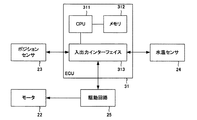
次に、ECUのハードウェア構成について説明する。図3は、ECUのハードウェア構成を示すブロック図である。 Next, the hardware configuration of the ECU will be described. FIG. 3 is a block diagram illustrating a hardware configuration of the ECU.
図3に示すように、ECU31は、CPU(Central Processing Unit)311、メモリ312、入出力インターフェイス313を備える。CPU311及びメモリ312は、協働して冷却水バルブ21の制御に係る処理を行う。また、入出力インターフェイス313はCPU311の入出力に係るインターフェイスであり、CPU311はこの入出力インターフェイス313を介してポジションセンサ23及び水温センサ24による検出結果を取得するとともに、入出力インターフェイス313を介してモータ22の操作量に応じた信号を駆動回路25に出力する。この駆動回路25は、モータ22をPWM(Pulse Width Modulation)制御するPWM回路であり、入力された信号の大きさに応じてパルス幅のデューティ比を変更することによりモータ22を駆動する。
As shown in FIG. 3, the
次に、バルブ制御装置の機能構成について説明する。なお、本実施の形態において、ECU31がバルブ制御装置として機能するものとする。図4は、バルブ制御装置の機能構成を示す機能ブロック図である。なお、以降の説明においては、制御対象を水冷バルブ21の開度に限定する。
Next, the functional configuration of the valve control device will be described. In the present embodiment, it is assumed that the
図4に示すように、バルブ制御装置5は、操作量算出部51、状態判断部52、第1補正部53、第2補正部54を機能として備える。なお、これらの機能は、上述したCPU311及びメモリ312が協働することにより実現されるものとする。
As shown in FIG. 4, the
操作量算出部51は、目標とするエンジン11の温度である目標温度、水温センサ24により検出された冷却水の温度に基づいて、エンジン11を目標温度とするために目標とするウォータージャケット12に対する冷却水の流量である目標流量を演算し、この目標流量に基づいて、目標とする冷却水バルブ21の開度である目標開度の値(目標値)を演算する。また、操作量算出部51は、演算した目標値と、フィードバックとしてのポジションセンサ23により検出された冷却水バルブ21の実開度(現在値)とに基づくPID制御によりモータ22に対する操作量を算出する。
The operation
なお、本実施の形態において、冷却水バルブ21の可動域は190°とし、モータ22の駆動に係る分解能を240とする。よって、本実施の形態においては、0.344度単位で冷却水バルブ21の開度を制御することとなる。また、操作量を正方向に増加させた場合に冷却水バルブ21は開方向に制御されるものとする。また、冷却水バルブ21の制御は、所定のサンプリング周期でなされるものとする。
In the present embodiment, the movable range of the cooling
また、状態判断部52は、冷却水バルブ21が定常状態または過渡状態のいずれであるかを判断する判断処理を行う。この判断処理については後述する。また、第1補正部53は、状態判断部52に定常状態と判断された場合に後述する定常状態補正処理を行う。また、第2補正処理部54は、状態判断部53に過渡状態と判断された場合に後述する過渡状態補正処理を行う。なお、定常状態補正処理及び過渡状態補正処理によりヒステリシス補正値が算出され、このヒステリシス補正値は操作量算出部51により算出された操作量に積分可算される。
In addition, the
次に、判断処理について説明する。図5は、判断処理の動作を示すフローチャートである。 Next, the determination process will be described. FIG. 5 is a flowchart showing the operation of the determination process.
図5に示すように、まず、状態判断部52は、制御偏差が0か否かを判断する(S101)。ここで制御偏差とは、冷却水バルブ21の目標値と現在値とに基づく制御偏差を示すものとする。
As shown in FIG. 5, first, the
制御偏差が0ではない場合(S101,NO)、状態判断部52は、操作量算出部51により演算された目標値が変更されたか否かを判断する(S102)。
When the control deviation is not 0 (S101, NO), the
目標値が変更された場合(S102,YES)、状態判断部52は、水冷バルブ21が定常状態であるか過渡状態であるかを示す変数gcに対して、過渡状態を示す0を代入し(S103)、再度、制御偏差が0であるか否かを判断する(S101)。
When the target value is changed (S102, YES), the
一方、目標値が変更されない場合(S102,NO)、状態判断部52は、制御偏差の符号が反転したか否かを判断する(S104)。ここで、判断部52は、前回のサンプルの制御偏差と比較することにより、現時点での制御偏差の符号が反転したか否かを判断するものとする。
On the other hand, when the target value is not changed (S102, NO), the
制御偏差の符号が反転した場合(S104,YES)、状態判断部52は、制御偏差の絶対値が3LSB以下か否かを判断する(S105)。
When the sign of the control deviation is inverted (S104, YES), the
制御偏差の絶対値が3LSB以下である場合(S105,YES)、状態判断部52は、変数gcに対して、定常状態を示す1を代入し(S106)、再度、制御偏差が0か否かを判断する(S101)。
When the absolute value of the control deviation is 3 LSB or less (S105, YES), the
一方、制御偏差の絶対値が3LSBより大きい場合(S105,NO)、状態判断部52は、変数gcに対して、過渡状態を示す0を代入し(S103)、再度、制御偏差が0か否かを判断する(S101)。
On the other hand, when the absolute value of the control deviation is larger than 3LSB (S105, NO), the
また、ステップS104の判断において、偏差の符号が反転していない場合(S104,NO)、状態判断部52は、変数gcに対して、過渡状態を示す0を代入し(S103)、再度、制御偏差が0か否かを判断する(S101)。
If the sign of the deviation is not inverted in the determination in step S104 (S104, NO), the
また、ステップS101の判断において、制御偏差が0である場合(S101,YES)、状態判断部52は、変数gcに対して、定常状態を示す1を代入し(S106)、再度、制御偏差が0か否かを判断する(S101)。
When the control deviation is 0 in the determination in step S101 (S101, YES), the
上述したように、状態判断部52は、制御偏差が0である場合と、目標値が変更されない状態において制御偏差の符号が反転し、且つ制御偏差の絶対値が所定の値以下である場合とに、冷却水バルブ21が定常状態であると判断する。なお、上述の処理において、状態判断部52は、変数gcへの代入後、次のサンプルを待機するものとする。
As described above, the
次に、定常状態補正処理について説明する。図6は、定常状態補正処理の動作を示すフローチャートである。 Next, the steady state correction process will be described. FIG. 6 is a flowchart showing the operation of the steady state correction process.
図6に示すように、まず、第1補正部53は、変数gcが1であるか否かを判断する(S201)。
As shown in FIG. 6, first, the
変数gcが1である場合(S201,YES)、第1補正部53は、制御偏差が0か否かを判断する(S202)。
When the variable gc is 1 (S201, YES), the
制御偏差が0ではない場合(S202,NO)、第1補正部53は、制御偏差が正値であるか否かを判断する(S203)。
When the control deviation is not 0 (S202, NO), the
制御偏差が正値である場合(S203,YES)、第1補正部53は、カウンタ変数hysspcに0を代入して初期化し(S204)、所定の正の補正値をヒステリシス補正値として出力し(S205)、変数hysspcをインクリメントして(S206)、次のサンプルを待機し、変数gcが1であるか否かを判断する(S207)。
When the control deviation is a positive value (S203, YES), the
変数gcが1である場合(S207,YES)、第1補正部53は、制御偏差が0であるか否かを判断する(S208)。
When the variable gc is 1 (S207, YES), the
制御偏差が0ではない場合(ステップS208,NO)、第1補正部53は、変数hysspcが所定の閾値を示す変数であるmaxc以上であるか否かを判断する(S209)。
When the control deviation is not 0 (step S208, NO), the
変数hysspcが変数maxc以上である場合(S209、YES)、第1補正部53は、定常状態補正処理を終了する。
When the variable hysspc is greater than or equal to the variable maxc (S209, YES), the
一方、変数hysspcが変数maxcより小さい場合(S209,NO)、第1補正部53は、再度、所定の正の補正値をヒステリシス補正値として出力する(S205)。
On the other hand, when the variable hyspcc is smaller than the variable maxc (S209, NO), the
また、ステップS208の判断において、制御偏差が0である場合(S208,YES)、第1補正部53は、定常状態補正処理を終了する。
If the control deviation is 0 in the determination in step S208 (S208, YES), the
また、ステップS207の判断において、変数gcが1ではない場合(S207,NO)、第1補正部53は、定常状態補正処理を終了する。
If the variable gc is not 1 in the determination in step S207 (S207, NO), the
また、ステップS203の判断において、制御偏差が負値である場合(S203,NO)、第1補正部53は、変数hyssmcに0を代入して初期化し(S210)、所定の負の補正値をヒステリシス補正値として出力し(S211)、変数hyssmcをインクリメントして(S212)、次のサンプルを待機し、変数gcが1であるか否かを判断する(S213)。
If the control deviation is negative in the determination in step S203 (S203, NO), the
変数gcが1である場合(S213,YES)、第1補正部53は、制御偏差が0であるか否かを判断する(S214)。
When the variable gc is 1 (S213, YES), the
制御偏差が0ではない場合(ステップS214,NO)、第1補正部53は、変数hyssmcが変数maxc以上であるか否かを判断する(S215)。
When the control deviation is not 0 (step S214, NO), the
変数hyssmcが変数maxc以上である場合(S215,YES)、第1補正部53は、定常状態補正処理を終了する。
When the variable hyssmc is greater than or equal to the variable maxc (S215, YES), the
一方、変数hyssmcが変数maxcより小さい場合(S215,NO)、第1補正部53は、所定の負の補正値をヒステリシス補正値として出力する(S211)。
On the other hand, when the variable hyssmc is smaller than the variable maxc (S215, NO), the
また、ステップS214の判断において、制御偏差が0である場合(S214,YES)、第1補正部53は、定常状態補正処理を終了する。
If the control deviation is 0 in the determination in step S214 (S214, YES), the
また、ステップS213の判断において、変数gcが1ではない場合(S213,NO)、第1補正部53は、定常状態補正処理を終了する。
If the variable gc is not 1 in the determination in step S213 (S213, NO), the
また、ステップS201の判断において、変数gcが1ではない場合(S201,NO)、第1補正部53は、次のサンプルを待機し、再度、変数gcが1であるか否かを判断する(S201)。
In step S201, if the variable gc is not 1 (S201, NO), the
上述したように、第1補正部53は、定常状態において制御偏差がある場合、その符号に応じて所定のヒステリシス補正値を出力する。また、第1補正部53は、ヒステリシス補正値の出力において、制御偏差が0にならず、且つヒステリシス補正値の出力回数が所定の閾値に達しない限り、所定のヒステリシス補正値を出力し続ける。つまり、第1補正部53は、複数回に分けてヒステリシス補正値を出力する。このような動作により、定常状態における冷却水バルブ21の制御性を向上させることができる。
As described above, when there is a control deviation in the steady state, the
次に、過渡状態補正処理について説明する。図7及び図8は、過渡状態補正処理の動作を示すフローチャートである。 Next, the transient state correction process will be described. 7 and 8 are flowcharts showing the operation of the transient state correction process.
図7に示すように、まず、第2補正部54は、変数gcが0であるか否かを判断する(S301)。
As shown in FIG. 7, first, the
変数gcが0である場合(S301,YES)、第2補正部54は、冷却水バルブ21の動作方向が開方向であるか否かを判断する(S302)。
When the variable gc is 0 (S301, YES), the
冷却水バルブ21の動作方向が開方向である場合(S302,YES)、第2補正部54は、所定の正の補正値をヒステリシス補正値として出力して(S303)、次のサンプルを待機し、変数gcが0であるか否かを判断する(S304)。
When the operation direction of the
変数gcが0である場合(S304,YES)、第2補正部54は、変数mnsが1且つ変数plsが0であるか否かを判断する(S305)。
When the variable gc is 0 (S304, YES), the
ここで、変数mns及び変数plsについて説明する。変数mnsは、前回サンプルの操作量に対して現在のサンプルの操作量が減少しており、且つ前回サンプルの操作量が前々回サンプルの操作量に対して減少していない場合に1となり、それ以外の場合に0となる。また、変数plsは、前回サンプルの操作量に対して現在のサンプルの操作量が増加しており、且つ前回サンプルの操作量が前々回サンプルの操作量に対して増加していない場合に1となり、それ以外の場合に0となる。 Here, the variable mns and the variable pls will be described. The variable mns is set to 1 when the operation amount of the current sample has decreased with respect to the operation amount of the previous sample and the operation amount of the previous sample has not decreased with respect to the operation amount of the previous sample, otherwise In this case, it becomes 0. The variable pls is 1 when the operation amount of the current sample has increased with respect to the operation amount of the previous sample, and the operation amount of the previous sample has not increased with respect to the operation amount of the previous sample, Otherwise it is 0.
変数mnsが1且つ変数plsが0である場合(S305,YES)、第2補正部54は、所定の負の補正値をヒステリシス補正値として出力して(S306)、次のサンプルを待機し、変数gcが0であるか否かを判断する(S307)。
When the variable mns is 1 and the variable pls is 0 (S305, YES), the
ステップS302の判断において、冷却水バルブ21の動作方向が閉方向である場合(S302,NO)、第2補正部54は、所定の負の補正値をヒステリシス補正値として出力して(S308)、次のサンプルを待機し、変数gcが0であるか否かを判断する(S309)。
If it is determined in step S302 that the operation direction of the cooling
変数gcが0である場合(S309,YES)、第2補正部54は、変数plsが1且つ変数mnsが0であるか否かを判断する(S310)。
When the variable gc is 0 (S309, YES), the
変数plsが1且つ変数mnsが0である場合(S310,YES)、第2補正部54は、所定の正の補正値をヒステリシス補正値として出力して(S311)、次のサンプルを待機し、変数gcが0であるか否かを判断する(S312)。
When the variable pls is 1 and the variable mns is 0 (S310, YES), the
変数gcが0である場合(S312,YES)、第2補正部54は、変数mnsが1且つ変数plsが0であるか否かを判断する(S305)。
When the variable gc is 0 (S312: YES), the
一方、変数gcが0ではない場合(S312,NO)、図8に示すように、第2補正部54は、過渡状態補正処理を終了する。
On the other hand, when the variable gc is not 0 (S312: NO), as shown in FIG. 8, the
また、ステップS307の判断において、変数gcが0である場合(S307,YES)、第2補正部54は、変数plsが1且つ変数mnsが0であるか否かを判断する(S310)。
If the variable gc is 0 in the determination in step S307 (S307, YES), the
また、ステップS307及びS312の判断において、変数gcが0ではない場合(S307,NO/S312,NO)、いずれの場合も、図8に示すように、第2補正部54は、過渡状態補正処理を終了する。
Further, in the determinations in steps S307 and S312, when the variable gc is not 0 (S307, NO / S312, NO), in any case, as shown in FIG. 8, the
また、ステップS305の判断において、変数mnsが1且つ変数plsが0ではない場合(S305,NO)、及びステップS310の判断において、変数plsが1且つ変数mnsが0ではない場合(S310,NO)、いずれの場合も、図8に示すように、第2補正部54は、後述するステップS313の処理を行う。
In the determination in step S305, when the variable mns is 1 and the variable pls is not 0 (S305, NO), and in the determination in step S310, the variable pls is 1 and the variable mns is not 0 (S310, NO). In any case, as shown in FIG. 8, the
また、ステップS301の判断において、変数gcが0ではない場合(S301,NO)、第2補正部54は、次のサンプルを待機し、再度、変数gcが0であるか否かを判断する(S301)。
If the variable gc is not 0 in the determination in step S301 (S301, NO), the
ここで、ステップS313移行の処理について説明する。図8に示すように、第2補正部54は、図8に示すように、補正値0を出力して(S313)、次のサンプルを待機し、変数gcが0であるか否かを判断する(S314)。
Here, the process of step S313 will be described. As shown in FIG. 8, the
変数gcが0である場合(S314,YES)、第2補正部54は、変数mnsが1且つ変数plsが0であるか否かを判断する(S315)。
When the variable gc is 0 (S314, YES), the
変数mnsが1且つ変数plsが0である場合(S315,YES)、第2補正部54は、図7に示すように、所定の負の補正値をヒステリシス補正値として出力する(S306)
When the variable mns is 1 and the variable pls is 0 (S315, YES), the
一方、変数mnsが1且つ変数plsが0ではない場合(S315,NO)、第2補正部54は、図7に示すように、所定の正の補正値をヒステリシス補正値として出力する(S311)。
On the other hand, when the variable mns is 1 and the variable pls is not 0 (S315, NO), the
また、ステップS314の判断において、変数gcが0ではない場合(S314,NO)、第2補正部54は、過渡状態補正処理を終了する。
If the variable gc is not 0 in the determination in step S314 (S314, NO), the
上述したように、第2補正部54は、過渡状態において、操作量が減少に転じた場合に負の補正値を出力し、操作量が増加に転じた場合に正の補正値を出力する。このような動作により、過渡状態における冷却水バルブ21の制御性を向上させることができる。
As described above, in the transient state, the
以上、説明したように、本実施の形態に係るバルブ制御装置5によれば、定常状態及び過渡状態に応じてヒステリシス補正値を出力することにより、特に定常状態において、冷却水バルブ21の目標開度への整定性を向上させることができる。また、これにより冷却水の流量の制御性が向上し、したがって、エンジン11の温度の制御性も向上させることができる。なお、本実施の形態において、バルブ制御装置5の制御対象を冷却水バルブ21としたが、バルブ制御装置5は流体の流量を制御するバルブであれば適用可能である。
As described above, according to the
本発明は、その要旨または主要な特徴から逸脱することなく、他の様々な形で実施することができる。そのため、前述の実施の形態は、あらゆる点で単なる例示に過ぎず、限定的に解釈してはならない。本発明の範囲は、特許請求の範囲によって示すものであって、明細書本文には、何ら拘束されない。更に、特許請求の範囲の均等範囲に属する全ての変形、様々な改良、代替および改質は、全て本発明の範囲内のものである。 The present invention can be implemented in various other forms without departing from the gist or main features thereof. Therefore, the above-described embodiment is merely an example in all respects and should not be interpreted in a limited manner. The scope of the present invention is shown by the scope of claims, and is not restricted by the text of the specification. Moreover, all modifications, various improvements, substitutions and modifications belonging to the equivalent scope of the claims are all within the scope of the present invention.
1 エンジン冷却システム、5 バルブ制御装置、11 エンジン、12 ウォータージャケット、13 ウォーターポンプ、21 冷却水バルブ、22 モータ、23 ポジションセンサ、24 水温センサ、31 ECU、41 ラジエータ、42 ヒータ、43 スロットル、51 操作量算出部、52 状態判断部、53 第1補正部、54 第2補正部、91 メイン流路パイプ、91a シール部材、92 サブ流路パイプ、92a シール部材、93 バイパス流路パイプ、311 CPU、312 メモリ、313 入出力インターフェイス。
DESCRIPTION OF
Claims (6)
前記バルブの開度の目標値と前記バルブの開度の実測値との制御偏差に基づいて、所定のサンプリング周期で前記駆動装置の操作量を算出する操作量算出部と、
前記目標値が変更されない状態において、前記制御偏差の符号が前回のサンプルにおける制御偏差の符号に対して反転し、且つ前記制御偏差の絶対値が所定の偏差閾値以下であるか否かを判断する判断部と、
前記判断部により、前記目標値が変更されない状態において、前記制御偏差の符号が前回のサンプルにおける制御偏差の符号に対して反転し、且つ前記制御偏差の絶対値が前記制御偏差閾値以下であると判断された場合、前記制御偏差の符号に応じた所定の第1補正値を出力し、前記操作量算出部で算出された操作量を該第1補正値で補正する第1補正部と
を備えるバルブ制御装置。 A valve control device for controlling a drive device for driving the valve,
An operation amount calculation unit that calculates an operation amount of the drive device at a predetermined sampling period based on a control deviation between a target value of the valve opening and an actual measurement of the valve opening;
In a state where the target value is not changed, it is determined whether or not the sign of the control deviation is inverted with respect to the sign of the control deviation in the previous sample and whether the absolute value of the control deviation is equal to or less than a predetermined deviation threshold value. A determination unit;
In a state where the target value is not changed by the determination unit , the sign of the control deviation is inverted with respect to the sign of the control deviation in the previous sample, and the absolute value of the control deviation is equal to or less than the control deviation threshold value. A first correction unit that outputs a predetermined first correction value corresponding to the sign of the control deviation and corrects the operation amount calculated by the operation amount calculation unit with the first correction value when determined. Valve control device.
請求項1に記載のバルブ制御装置。 The first correction unit may continue the output of the first correction value until the control deviation becomes zero when the number of outputs of the first correction value is less than a predetermined first threshold.
The valve control device according to claim 1.
請求項1または請求項2に記載のバルブ制御装置。 When the determination unit determines that the absolute value of the control deviation is larger than the deviation threshold value, the predetermined second correction value corresponding to the change in the operation amount is output, and the operation calculated by the operation amount calculation unit A second correction unit for correcting the amount with the second correction value;
The valve control device according to claim 1 or 2 .
前記バルブの開度の目標値と前記バルブの開度の実測値との制御偏差に基づいて、所定のサンプリング周期で前記駆動装置の操作量を算出し、
前記目標値が変更されない状態において、前記制御偏差の符号が前回のサンプルにおける制御偏差の符号に対して反転し、且つ前記制御偏差の絶対値が所定の偏差閾値以下であるか否かを判断し、
前記目標値が変更されない状態において、前記制御偏差の符号が前回のサンプルにおける制御偏差の符号に対して反転し、且つ前記制御偏差の絶対値が所定の偏差閾値以下であると判断した場合、前記制御偏差の符号に応じた所定の第1補正値を出力し、前記算出した操作量を該第1補正値で補正する、
ことをコンピュータに実行させるバルブ制御方法。 A valve control method for controlling a drive device for driving a valve,
Based on the control deviation between the target value of the valve opening and the actual measured value of the valve opening, the operation amount of the drive device is calculated at a predetermined sampling period,
In a state where the target value is not changed, it is determined whether the sign of the control deviation is inverted with respect to the sign of the control deviation in the previous sample, and whether the absolute value of the control deviation is equal to or less than a predetermined deviation threshold value. ,
In a state where the target value is not changed, when it is determined that the sign of the control deviation is inverted with respect to the sign of the control deviation in the previous sample and the absolute value of the control deviation is equal to or less than a predetermined deviation threshold, Outputting a predetermined first correction value corresponding to the sign of the control deviation, and correcting the calculated operation amount with the first correction value;
A valve control method that causes a computer to execute this.
請求項4に記載のバルブ制御方法。 When the number of outputs of the first correction value is less than a predetermined first threshold, the output of the first correction value is continued until the control deviation becomes zero,
The valve control method according to claim 4 .
ことを更にコンピュータに実行させる請求項4または請求項5に記載のバルブ制御方法。 When it is determined that the absolute value of the control deviation is larger than the deviation threshold, a predetermined second correction value corresponding to the change in the operation amount is output, and the calculated operation amount is corrected with the second correction value.
The valve control method according to claim 4 or 5 , further causing a computer to execute this.
Priority Applications (7)
| Application Number | Priority Date | Filing Date | Title |
|---|---|---|---|
| JP2013028595A JP6301061B2 (en) | 2013-02-18 | 2013-02-18 | Valve control device and valve control method |
| KR1020157020347A KR20150118114A (en) | 2013-02-18 | 2014-01-30 | Valve control device and valve control method |
| US14/765,641 US10228707B2 (en) | 2013-02-18 | 2014-01-30 | Valve control device and valve control method |
| CN201480009229.XA CN105074158B (en) | 2013-02-18 | 2014-01-30 | Control valve device and valve control method |
| EP14751093.7A EP2957742B1 (en) | 2013-02-18 | 2014-01-30 | Valve control device and valve control method |
| MYPI2015702678A MY176623A (en) | 2013-02-18 | 2014-01-30 | Valve control device and valve control method |
| PCT/JP2014/052079 WO2014125929A1 (en) | 2013-02-18 | 2014-01-30 | Valve control device and valve control method |
Applications Claiming Priority (1)
| Application Number | Priority Date | Filing Date | Title |
|---|---|---|---|
| JP2013028595A JP6301061B2 (en) | 2013-02-18 | 2013-02-18 | Valve control device and valve control method |
Publications (2)
| Publication Number | Publication Date |
|---|---|
| JP2014156828A JP2014156828A (en) | 2014-08-28 |
| JP6301061B2 true JP6301061B2 (en) | 2018-03-28 |
Family
ID=51353938
Family Applications (1)
| Application Number | Title | Priority Date | Filing Date |
|---|---|---|---|
| JP2013028595A Active JP6301061B2 (en) | 2013-02-18 | 2013-02-18 | Valve control device and valve control method |
Country Status (7)
| Country | Link |
|---|---|
| US (1) | US10228707B2 (en) |
| EP (1) | EP2957742B1 (en) |
| JP (1) | JP6301061B2 (en) |
| KR (1) | KR20150118114A (en) |
| CN (1) | CN105074158B (en) |
| MY (1) | MY176623A (en) |
| WO (1) | WO2014125929A1 (en) |
Families Citing this family (9)
| Publication number | Priority date | Publication date | Assignee | Title |
|---|---|---|---|---|
| JP6737570B2 (en) * | 2015-06-11 | 2020-08-12 | 株式会社ミクニ | Valve control device |
| JP2017067016A (en) * | 2015-09-30 | 2017-04-06 | アイシン精機株式会社 | Cooling control device |
| JP6493146B2 (en) * | 2015-10-19 | 2019-04-03 | 株式会社デンソー | Valve control device |
| JP6477636B2 (en) * | 2016-09-07 | 2019-03-06 | トヨタ自動車株式会社 | Control device for internal combustion engine |
| JP2018044510A (en) * | 2016-09-16 | 2018-03-22 | 株式会社山田製作所 | Control device and program |
| JP6805094B2 (en) * | 2017-07-21 | 2020-12-23 | トヨタ自動車株式会社 | Internal combustion engine cooling system |
| JP7337012B2 (en) * | 2020-03-17 | 2023-09-01 | 川崎重工業株式会社 | CONTROLLER AND HYDRAULIC SYSTEM INCLUDING THE SAME |
| JP7444740B2 (en) | 2020-09-07 | 2024-03-06 | 株式会社ミクニ | engine cooling system |
| US11802632B2 (en) * | 2021-06-29 | 2023-10-31 | Textron Innovations Inc. | Modulating butterfly valve control |
Family Cites Families (10)
| Publication number | Priority date | Publication date | Assignee | Title |
|---|---|---|---|---|
| JPS6161938A (en) * | 1984-09-01 | 1986-03-29 | Hitachi Ltd | Engine controller |
| US5170860A (en) * | 1990-03-27 | 1992-12-15 | Honda Giken Kogyo K.K. | Driving wheel control system for automotive vehicles |
| JP3656892B2 (en) * | 1999-09-07 | 2005-06-08 | 横河電機株式会社 | Valve positioner |
| KR100509145B1 (en) * | 2000-02-25 | 2005-08-18 | 미쓰비시덴키 가부시키가이샤 | Controller of exhaust gas recirculation valve |
| JP3915966B2 (en) * | 2001-10-15 | 2007-05-16 | 日本サーモスタット株式会社 | Control method of electronic control thermostat |
| JP3932277B2 (en) * | 2002-10-18 | 2007-06-20 | 日本サーモスタット株式会社 | Control method of electronic control thermostat |
| JP4989252B2 (en) * | 2007-02-20 | 2012-08-01 | 株式会社ミクニ | Electronic control device and feedback control method |
| US8671973B2 (en) | 2009-01-21 | 2014-03-18 | Hitachi Metals, Ltd. | Mass flow controller hysteresis compensation system and method |
| JP5793320B2 (en) * | 2011-03-18 | 2015-10-14 | ヤンマー株式会社 | engine |
| JP5910874B2 (en) * | 2012-04-10 | 2016-04-27 | 株式会社ジェイテクト | Hydraulic power steering device |
-
2013
- 2013-02-18 JP JP2013028595A patent/JP6301061B2/en active Active
-
2014
- 2014-01-30 US US14/765,641 patent/US10228707B2/en not_active Expired - Fee Related
- 2014-01-30 MY MYPI2015702678A patent/MY176623A/en unknown
- 2014-01-30 EP EP14751093.7A patent/EP2957742B1/en active Active
- 2014-01-30 KR KR1020157020347A patent/KR20150118114A/en unknown
- 2014-01-30 WO PCT/JP2014/052079 patent/WO2014125929A1/en active Application Filing
- 2014-01-30 CN CN201480009229.XA patent/CN105074158B/en not_active Expired - Fee Related
Also Published As
| Publication number | Publication date |
|---|---|
| KR20150118114A (en) | 2015-10-21 |
| US10228707B2 (en) | 2019-03-12 |
| MY176623A (en) | 2020-08-18 |
| EP2957742B1 (en) | 2020-04-22 |
| US20150370261A1 (en) | 2015-12-24 |
| EP2957742A1 (en) | 2015-12-23 |
| JP2014156828A (en) | 2014-08-28 |
| EP2957742A4 (en) | 2016-10-12 |
| CN105074158B (en) | 2017-10-31 |
| CN105074158A (en) | 2015-11-18 |
| WO2014125929A1 (en) | 2014-08-21 |
Similar Documents
| Publication | Publication Date | Title |
|---|---|---|
| JP6301061B2 (en) | Valve control device and valve control method | |
| CN109555592B (en) | Engine cooling device | |
| KR101694043B1 (en) | Control method of intergrated flow control valve | |
| JP2017067016A (en) | Cooling control device | |
| JP6154159B2 (en) | Flow control device, flow control method | |
| WO2016163002A1 (en) | Actuator controller, actuator, valve driving device, and actuator control method | |
| WO2016163001A1 (en) | Actuator controller, actuator, valve driving device, and actuator control method | |
| JP4529856B2 (en) | Valve control device | |
| WO2016199559A1 (en) | Valve control device and valve control method | |
| JP6192340B2 (en) | Valve control device | |
| JP6200661B2 (en) | Control apparatus and control method | |
| JP6220135B2 (en) | Exhaust gas recirculation device | |
| JP6377316B2 (en) | Valve control device | |
| JP6691355B2 (en) | Flow controller | |
| JP6582831B2 (en) | Cooling control device | |
| JP6026198B2 (en) | Electronic control unit | |
| KR101673557B1 (en) | Mechanical stop position learning method of continuous variable valve lift system | |
| JP6018019B2 (en) | Variable valve timing control device for internal combustion engine | |
| JP6095926B2 (en) | Electronic control unit |
Legal Events
| Date | Code | Title | Description |
|---|---|---|---|
| A621 | Written request for application examination |
Free format text: JAPANESE INTERMEDIATE CODE: A621 Effective date: 20151124 |
|
| A131 | Notification of reasons for refusal |
Free format text: JAPANESE INTERMEDIATE CODE: A131 Effective date: 20160920 |
|
| A521 | Request for written amendment filed |
Free format text: JAPANESE INTERMEDIATE CODE: A523 Effective date: 20161117 |
|
| A131 | Notification of reasons for refusal |
Free format text: JAPANESE INTERMEDIATE CODE: A131 Effective date: 20170214 |
|
| A131 | Notification of reasons for refusal |
Free format text: JAPANESE INTERMEDIATE CODE: A131 Effective date: 20170919 |
|
| A521 | Request for written amendment filed |
Free format text: JAPANESE INTERMEDIATE CODE: A523 Effective date: 20171102 |
|
| TRDD | Decision of grant or rejection written | ||
| A01 | Written decision to grant a patent or to grant a registration (utility model) |
Free format text: JAPANESE INTERMEDIATE CODE: A01 Effective date: 20180206 |
|
| A61 | First payment of annual fees (during grant procedure) |
Free format text: JAPANESE INTERMEDIATE CODE: A61 Effective date: 20180228 |
|
| R150 | Certificate of patent or registration of utility model |
Ref document number: 6301061 Country of ref document: JP Free format text: JAPANESE INTERMEDIATE CODE: R150 |
|
| R250 | Receipt of annual fees |
Free format text: JAPANESE INTERMEDIATE CODE: R250 |
|
| R250 | Receipt of annual fees |
Free format text: JAPANESE INTERMEDIATE CODE: R250 |
|
| R250 | Receipt of annual fees |
Free format text: JAPANESE INTERMEDIATE CODE: R250 |
|
| R250 | Receipt of annual fees |
Free format text: JAPANESE INTERMEDIATE CODE: R250 |