EP2333255A2 - Fossil fuel combustion thermal power system including carbon dioxide separation and capture unit - Google Patents
Fossil fuel combustion thermal power system including carbon dioxide separation and capture unit Download PDFInfo
- Publication number
- EP2333255A2 EP2333255A2 EP10192643A EP10192643A EP2333255A2 EP 2333255 A2 EP2333255 A2 EP 2333255A2 EP 10192643 A EP10192643 A EP 10192643A EP 10192643 A EP10192643 A EP 10192643A EP 2333255 A2 EP2333255 A2 EP 2333255A2
- Authority
- EP
- European Patent Office
- Prior art keywords
- pressure turbine
- steam
- carbon dioxide
- fossil fuel
- pipe
- Prior art date
- Legal status (The legal status is an assumption and is not a legal conclusion. Google has not performed a legal analysis and makes no representation as to the accuracy of the status listed.)
- Granted
Links
Images


Classifications
-
- F—MECHANICAL ENGINEERING; LIGHTING; HEATING; WEAPONS; BLASTING
- F01—MACHINES OR ENGINES IN GENERAL; ENGINE PLANTS IN GENERAL; STEAM ENGINES
- F01K—STEAM ENGINE PLANTS; STEAM ACCUMULATORS; ENGINE PLANTS NOT OTHERWISE PROVIDED FOR; ENGINES USING SPECIAL WORKING FLUIDS OR CYCLES
- F01K7/00—Steam engine plants characterised by the use of specific types of engine; Plants or engines characterised by their use of special steam systems, cycles or processes; Control means specially adapted for such systems, cycles or processes; Use of withdrawn or exhaust steam for feed-water heating
- F01K7/16—Steam engine plants characterised by the use of specific types of engine; Plants or engines characterised by their use of special steam systems, cycles or processes; Control means specially adapted for such systems, cycles or processes; Use of withdrawn or exhaust steam for feed-water heating the engines being only of turbine type
-
- F—MECHANICAL ENGINEERING; LIGHTING; HEATING; WEAPONS; BLASTING
- F01—MACHINES OR ENGINES IN GENERAL; ENGINE PLANTS IN GENERAL; STEAM ENGINES
- F01K—STEAM ENGINE PLANTS; STEAM ACCUMULATORS; ENGINE PLANTS NOT OTHERWISE PROVIDED FOR; ENGINES USING SPECIAL WORKING FLUIDS OR CYCLES
- F01K13/00—General layout or general methods of operation of complete plants
-
- F—MECHANICAL ENGINEERING; LIGHTING; HEATING; WEAPONS; BLASTING
- F01—MACHINES OR ENGINES IN GENERAL; ENGINE PLANTS IN GENERAL; STEAM ENGINES
- F01K—STEAM ENGINE PLANTS; STEAM ACCUMULATORS; ENGINE PLANTS NOT OTHERWISE PROVIDED FOR; ENGINES USING SPECIAL WORKING FLUIDS OR CYCLES
- F01K17/00—Using steam or condensate extracted or exhausted from steam engine plant
- F01K17/04—Using steam or condensate extracted or exhausted from steam engine plant for specific purposes other than heating
-
- F—MECHANICAL ENGINEERING; LIGHTING; HEATING; WEAPONS; BLASTING
- F01—MACHINES OR ENGINES IN GENERAL; ENGINE PLANTS IN GENERAL; STEAM ENGINES
- F01K—STEAM ENGINE PLANTS; STEAM ACCUMULATORS; ENGINE PLANTS NOT OTHERWISE PROVIDED FOR; ENGINES USING SPECIAL WORKING FLUIDS OR CYCLES
- F01K7/00—Steam engine plants characterised by the use of specific types of engine; Plants or engines characterised by their use of special steam systems, cycles or processes; Control means specially adapted for such systems, cycles or processes; Use of withdrawn or exhaust steam for feed-water heating
- F01K7/16—Steam engine plants characterised by the use of specific types of engine; Plants or engines characterised by their use of special steam systems, cycles or processes; Control means specially adapted for such systems, cycles or processes; Use of withdrawn or exhaust steam for feed-water heating the engines being only of turbine type
- F01K7/22—Steam engine plants characterised by the use of specific types of engine; Plants or engines characterised by their use of special steam systems, cycles or processes; Control means specially adapted for such systems, cycles or processes; Use of withdrawn or exhaust steam for feed-water heating the engines being only of turbine type the turbines having inter-stage steam heating
-
- Y—GENERAL TAGGING OF NEW TECHNOLOGICAL DEVELOPMENTS; GENERAL TAGGING OF CROSS-SECTIONAL TECHNOLOGIES SPANNING OVER SEVERAL SECTIONS OF THE IPC; TECHNICAL SUBJECTS COVERED BY FORMER USPC CROSS-REFERENCE ART COLLECTIONS [XRACs] AND DIGESTS
- Y02—TECHNOLOGIES OR APPLICATIONS FOR MITIGATION OR ADAPTATION AGAINST CLIMATE CHANGE
- Y02E—REDUCTION OF GREENHOUSE GAS [GHG] EMISSIONS, RELATED TO ENERGY GENERATION, TRANSMISSION OR DISTRIBUTION
- Y02E20/00—Combustion technologies with mitigation potential
- Y02E20/32—Direct CO2 mitigation
Definitions
- the present invention relates to a fossil fuel combustion thermal power system including a carbon dioxide separation and capture unit.
- a fossil fuel combustion thermal power system including a carbon dioxide separation and capture unit relating to the present invention
- a system including a PCC unit (PCC: post combustion CO 2 capture) for separating and capturing carbon dioxide from fossil fuel, for example, the exhaust gas of a coal combustion boiler.
- PCC unit post combustion CO 2 capture
- a carbon dioxide capture system including a steam turbine having a high-pressure turbine, an intermediate-pressure turbine, and a low-pressure turbine, a boiler for generating steam for driving these turbines, a carbon dioxide absorption tower having a carbon dioxide absorbing solution for absorbing and removing carbon dioxide from the combustion exhaust gas of the boiler, a reproduction tower for reproducing the carbon dioxide absorbing solution absorbing carbon dioxide, a compressor for compressing the removed carbon dioxide, a turbine for the compressor driven by a part of the exhaust steam exhausted from the high-pressure turbine, a turbine for an auxiliary unit driven by a part of the exhaust steam exhausted from the intermediate-pressure turbine, and a supply pipe for supplying exhaust steam exhausted from the turbine for the compressor and the turbine for the auxiliary unit to the reboiler of the reproduction tower as a heating source, is disclosed.
- the absorbing solution circulation pump is driven so as to circulate the absorbing solution between the absorption tower and the reproduction tower, and the carbon dioxide included in the exhaust gas of the boiler is absorbed by the absorbing solution in the absorption tower, and the carbon dioxide absorbed by the absorbing solution is separated and captured by the reproduction tower.
- the carbon dioxide component in the exhaust gas of the boiler and the absorbing solution are permitted to make contact with each other in the absorption tower, and by a chemical reaction (heat generation reaction) of the absorbing solution at about 40°C with the carbon dioxide in the gas, the carbon dioxide is absorbed.
- a carbon-dioxide-enriched absorbing solution at about 70°C due to the chemical reaction of the absorbing solution with the carbon dioxide at this time leaves the absorption tower, then exchanges heat with a reproduced absorbing solution (called a lean absorbing solution) at about 120°C supplied from the reproduction tower, is heated up to about 110°C, and flows again into the absorption tower.
- a reproduced absorbing solution called a lean absorbing solution
- the enriched absorbing solution after heat exchange is heated again to 120°C to 130°C in the reproduction tower and separates the carbon dioxide absorbed by the enriched absorbing solution.
- the absorbing solution separating the carbon dioxide by the reproduction tower becomes a lean absorbing solution, is introduced again into the absorption tower, and absorbs carbon dioxide in the exhaust gas of the boiler.
- the absorbing solution in the reproduction tower is heated so as to separate the carbon dioxide and become the lean absorbing solution, so that the reboiler for supplying heating steam to the reproduction tower must generate a large quantity of steam.
- An object of the present invention is to provide a fossil fuel combustion thermal power system including a carbon dioxide separation and capture unit capable of suppressing a load change caused to the fossil fuel combustion thermal power system when the carbon dioxide separation and capture unit urgently stops the operation.
- the present invention of a fossil fuel combustion thermal power system including a carbon dioxide separation and capture unit comprising: a fossil fuel combustion thermal power system including a boiler for burning fossil fuel and generating steam and a steam turbine including a high-pressure turbine driven by the steam generated by the boiler for generating power, and a carbon dioxide separation and capture unit including an absorption tower for absorbing and capturing carbon dioxide included in the exhaust gas discharged from the boiler by burning fossil fuel in the boiler of the fossil fuel combustion thermal power system and a reproduction tower of an absorbing solution for separating carbon dioxide from the absorbing solution absorbing carbon dioxide by circulating the absorbing solution between the reproduction tower and the absorption tower, the fossil fuel combustion thermal power system including the carbon dioxide separation and capture unit further comprising: a back-pressure turbine driven by extraction steam extracted from the high-pressure turbine of the fossil fuel combustion thermal power system through an extraction pipe; a reboiler for supplying heating steam to the reproduction tower of the carbon dioxide separation and capture unit; a steam pipe for supplying steam flowing down through the back-pressure turbine of the fossil fuel combustion thermal
- a fossil fuel combustion thermal power system including a carbon dioxide separation and capture unit
- a fossil fuel combustion thermal power system including a boiler for burning fossil fuel and generating steam and a steam turbine including a high-pressure turbine and a intermediate-pressure turbine driven by the steam generated by the boiler for generating power
- a carbon dioxide separation and capture unit including an absorption tower for absorbing and capturing carbon dioxide included in the exhaust gas discharged from the boiler by burning fossil fuel in the boiler of the fossil fuel combustion thermal power system and a reproduction tower of an absorbing solution for separating carbon dioxide from the absorbing solution absorbing carbon dioxide by circulating the absorbing solution between the reproduction tower and the absorption tower
- the fossil fuel combustion thermal power system including'the carbon dioxide separation and capture unit further comprising: a reheat steam extraction pipe branching from a high-temperature reheat steam pipe for supplying reheat steam reheated by the boiler to the intermediate-pressure turbine from the boiler of the fossil fuel combustion thermal power system; a temperature lowering unit for lowering a temperature of the reheat steam extracted
- the present invention of a fossil fuel combustion thermal power system including a carbon dioxide separation and capture unit comprising: a fossil fuel combustion thermal power system including a boiler for burning fossil fuel and generating steam and a steam turbine including a high-pressure turbine and a intermediate-pressure turbine driven by the steam generated by the boiler for generating power, and a carbon dioxide separation and capture unit including an absorption tower for absorbing and capturing carbon dioxide included in the exhaust gas discharged from the boiler by burning fossil fuel in the boiler of the fossil fuel combustion thermal power system and a reproduction tower of an absorbing solution for separating carbon dioxide from the absorbing solution absorbing carbon dioxide by circulating the absorbing solution between the reproduction tower and the absorption tower, the fossil fuel combustion thermal power system including the carbon dioxide separation and capture unit further comprising: a back-pressure turbine driven by the extraction steam extracted from the high-pressure turbine of the fossil fuel combustion thermal power system through a first extraction pipe; a second steam extraction pipe for branching a part of the exhaust steam of the intermediate-pressure turbine supplied from the intermediate-pressure turbine of the fossil fuel combustion thermal power system
- a fossil fuel combustion thermal power system including a carbon dioxide separation and capture unit capable of suppressing the load change of the fossil fuel combustion thermal power system can be realized.
- the fossil fuel combustion thermal power system including the carbon dioxide separation and capture unit which is an embodiment of the present invention will be explained below with reference to the accompanying drawings.
- the fossil fuel combustion thermal power system including the carbon dioxide separation and capture unit of the first embodiment of the present invention will be explained by referring to Figs. 1 and 2 .
- Fig. 1 shows the fossil fuel combustion thermal power system including the carbon dioxide separation and capture unit of the first embodiment of the present invention.
- a fossil fuel combustion thermal power system 100 composing the fossil fuel combustion thermal power system including the carbon dioxide separation and capture unit of the first embodiment shown in Fig. 1 includes a fossil fuel combustion boiler 101 for burning fossil fuel, heating condensed water supplied from a condenser, and generating steam at a high temperature and high pressure and a high-pressure turbine 103 for leading and driving the steam generated by the boiler 101 through a main steam pipe 102 from the boiler 101.
- the steam decompressed due to an occurrence of power by the high-pressure turbine 103 for flowing down through an exhaust pipe 104 of the high-pressure turbine is supplied to the boiler 101 through a low-temperature reheat steam pipe 114 and is heated again by the boiler 101 to reheat the steam.
- the system includes an intermediate-pressure turbine 116 for leading and driving the reheat steam heated by the boiler 101 through a high-temperature reheat steam pipe 115 from the boiler 101 and the steam reduced in pressure due to an occurrence of power by the intermediate-pressure turbine 116 for flowing down through an exhaust pipe 117 of the intermediate-pressure turbine from the intermediate-pressure turbine 116 is supplied to a low-pressure turbine 118 (not drawn).
- the output of the steam turbine is taken out as power. Further, the numeral 175 indicates a deaerator.
- a first extraction pipe 105 branching from the low-temperature reheat steam pipe 114 for supplying the steam flowing down through the high-temperature turbine exhaust pipe 104 of the high-pressure turbine 103 to the boiler 101 for extracting a part of the steam flowing down through the low-temperature reheat steam pipe 114 in order to drive the back-pressure turbine and a back-pressure turbine 107 driven by the steam extracted through the first extraction pipe 105 are installed.
- a back-pressure turbine control valve 106 for controlling the output of the back-pressure turbine 107 is installed and on the exit side of the back-pressure turbine 107, an exhaust pipe path 108 (of the back-pressure turbine) for permitting the exhaust gas of the back-pressure turbine via the back-pressure turbine 107 to flow down, an exhaust pressure control valve 109 of the back-pressure turbine installed in the exhaust pipe path 108 of the back-pressure turbine for adjusting the pressure of the flowing exhaust gas of the back-pressure turbine, and an exit blast pipe 110 of the back-pressure turbine interconnected to the exhaust pipe path 108 of the back-pressure turbine for sending the exhaust gas of the back-pressure turbine to a reboiler 120 and a reclaimer 121 which are installed in a carbon dioxide separation and capture unit 200 which will be described later are installed.
- a back-pressure turbine generator 113 is installed and it is structured so as to take out the power of the back-pressure turbine 107 as electric power.
- a first emergency relief pipe 112 including a first emergency relief valve 111 is interconnected.
- the extraction steam which flows down in the high-pressure turbine 103 through the first extraction pipe 105 branching from the low-temperature reheat steam pipe 114 and is supplied to the back-pressure turbine 107 is structured so as to open the first emergency relief valve 111 installed in the first emergency relief pipe 112 and flow down into the condenser through the first emergency relief pipe 112.
- the fossil fuel combustion thermal power system 100 and the carbon dioxide separation and capture unit 200 for separating and capturing the carbon dioxide included in the exhaust gas of the boiler discharged from the boiler 101 of the fossil fuel combustion thermal power system 100 by burning fossil fuel are installed.
- the boiler exhaust gas including carbon dioxide which is discharged from the boiler 101 and is branched and supplied from a boiler exhaust gas system pipe 171 flows down through a boiler exhaust gas pipe 140, is boosted by a boiler exhaust gas boost fan 141 installed in the boiler exhaust gas pipe 140, then is supplied to and cooled by a boiler exhaust gas cooler 142, and is supplied to an absorption tower 126 for absorbing carbon dioxide gas from the boiler exhaust gas cooler 142 by the absorbing solution.
- the carbon dioxide gas included in the boiler exhaust gas is absorbed by the absorbing solution in the absorption tower 126 and the processed gas which is boiler exhaust gas including no carbon dioxide is supplied to a chimney 146 from the absorption tower 126 through an exit boiler exhaust gas pipe 145 of the absorption tower and is discharged from the chimney 146 into the atmosphere.
- the boiler exhaust gas not supplied to the absorption tower 126 by a valve opening operation of a bypass butterfly valve 143 installed on a bypass gas pipe 144 for bypassing the carbon dioxide separation and capture unit 200, is directly led to the chimney 146 through the bypass gas pipe 144.
- the enriched absorbing solution absorbing carbon dioxide gas included in the boiler exhaust gas supplied from the boiler 101 in the absorption tower 126 and including much carbon dioxide is boosted by an enriched absorbing solution transfer pump 127 installed in the supply path of the absorbing solution for supplying the absorbing solution of the absorption tower 126 to a reproduction tower 123, is supplied to an absorbing solution heat exchanger 128 similarly installed in the supply path of the absorbing solution, is heated by the absorbing solution heat exchanger 128, and then is supplied to the reproduction tower 123.
- the enriched absorbing solution supplied from the absorption tower 126 to the reproduction tower 123 is heated by supplying vapor generated by being heated by the back-pressure turbine exhaust steam supplied to the reboiler 120 and reclaimer 121 as a heat source to the reproduction tower 123 from the reboiler 120 and reclaimer 121 and the carbon oxide gas absorbed by the enriched absorbing solution in the reproduction tower 123 is separated from the enriched absorbing solution.
- the carbon dioxide separated from the enriched absorbing solution in the reproduction tower 123 is discharged from the reproduction tower 123, though it is cooled by an exit gas cooler 131 installed on the exit side of the reproduction tower 123 and then is supplied to a reflux drum 132 for separating moisture, and the moisture included in the carbon dioxide gas is separated, and only the carbon oxide gas is supplied to and stored in a carbon dioxide liquefying and storing facility (not drawn) from the reflux drum 132 through a carbon dioxide gas exhaust pipe 147.
- the moisture separated by the reflux drum 132 is structured so as to be boosted by a reflux drum pump 133 and be returned to the reproduction tower 123.
- a part of the absorbing solution in the reproduction tower 123 is pulled out through an absorbing solution pull-out pipe 124 in the reproduction tower and is branched and supplied to the reboiler 120 and reclaimer 121 and it is heated by the reboiler 120 to which the back-pressure turbine exhaust steam flowing down through the back-pressure turbine 107 driven by the heating steam extracted from the steam turbine cycle of the fossil fuel combustion thermal power system 100, that is, the extraction steam extracted from the high-pressure turbine 103 is supplied as a heat source.
- the reclaimer 121 is a cleaning unit of the absorbing solution for heating the absorbing solution by using the back-pressure turbine exhaust steam flowing down through the back-pressure turbine 107 as a heat source, separating impurities included in the absorbing solution, and discharging them out of the system.
- the heating steam necessary to heat the reboiler 120 and reclaimer 121 is obtained by sending the back-pressure turbine exhaust steam flowing down through the back-pressure turbine 107 composing the fossil fuel combustion thermal power system 100 to the reboiler 120 and reclaimer 121 through the back-pressure turbine exhaust pipe 110.
- the absorbing solution separating carbon dioxide by heating the absorbing solution in the reproduction tower 123 is boosted by a lean absorbing solution transfer pump 129 installed in the return path of the absorbing solution for returning the absorbing solution from the reproduction tower 123 to the absorption tower 126, is supplied to a lean absorbing solution cooler 130 similarly installed in the return path of the absorbing solution, is cooled by the lean absorbing solution cooler 130, and then is returned to the absorption tower 126, thus the absorbing solution is circulated between the absorption tower 126 and the reproduction tower 123.
- the system is structured so as to supply the back-pressure turbine exhaust steam flowing down from the back-pressure turbine 107 through the back-pressure turbine exhaust pipe 110 to the reboiler 120 and reclaimer 121 as a heat source, indirectly heat the absorbing solution pulled out from the reproduction tower 123 through the absorbing solution pull-out pipe 124 in the reproduction tower by the reboiler 120, generate clean steam at a desired temperature and pressure, and supply the generated steam to the reproduction tower 123 through a steam pipe 125 at the reboiler exit.
- a reboiler heating steam pressure control valve 134 and a reclaimer heating steam pressure control valve 135 are installed, thus the flow rate of the back-pressure turbine exhaust steam supplied to the reboiler 120 is adjusted so as to control the steam generated by the reboiler 120 to a desired temperature and pressure.
- a boiler and a reclaimer heating steam drain pipe 122 for leading the back-pressure turbine exhaust steam which is used by the reboiler 120 and reclaimer 121 as a heat source and is lowered in temperature to the drain capture system of the turbine condensate system are arranged.
- Fig. 2 is a partial diagram showing the portion of the fossil fuel combustion thermal power system 100 of the fossil fuel combustion thermal power system including the carbon dioxide separation and capture unit of the first embodiment shown in Fig. 1 .
- the first emergency relief pipe 112 including the first emergency relief valve 111 interconnected to the low-temperature reheat steam pipe 114 through which the steam flowing down from the high-pressure turbine 103 through the exhaust pipe 104 of the high-pressure turbine flows for permitting the steam flowing into the low-temperature reheat steam pipe 114 to bypass the back-pressure turbine 107 and to be discharged to a condenser (not shown) is arranged.
- control unit 300 installed and by the turbine control unit 300, the operation of the back-pressure turbine 107 is controlled.
- the opening angle of a first back-pressure turbine control valve 106 is adjusted and the flow rate of steam supplied to the back-pressure turbine 107 is controlled. Further, by the instruction signal of the control unit 300, the opening angle of a back-pressure turbine exhaust pressure regulating valve 109 is adjusted and the pressure of the back-pressure turbine exhaust steam which flows down in the back-pressure turbine 107, flows in the exit blast pipe 110 of the back-pressure turbine on the downstream side of the back-pressure turbine exhaust pressure regulating valve 109, and is supplied to the reboiler 120 is controlled.
- the main unit of the carbon dioxide separation and capture unit 200 trips by some cause, for example, when the enriched absorbing solution transfer pump 127 for transferring the absorbing solution or the lean absorbing solution transfer pump 129 trips and the operation of the carbon dioxide separation and capture unit 200 stops urgently, the surplus steam (in the normal operation, from the back-pressure turbine 107 to the reboiler 120, the back-pressure turbine exhaust steam flowing down in the back-pressure turbine 107 is supplied as a heat source) supplied from the fossil fuel combustion thermal power system 100 to the carbon dioxide separation and capture unit 200 is permitted to bypass the back-pressure turbine 107 and to shift to the condenser through the first emergency relief pipe 112 including the first emergency relief valve 111.
- the surplus steam in the normal operation, from the back-pressure turbine 107 to the reboiler 120, the back-pressure turbine exhaust steam flowing down in the back-pressure turbine 107 is supplied as a heat source
- the steam quantity required by the reboiler 120 is far larger than the steam quantity required by the reclaimer 121 and is equivalent to about 15% to 20% of the total quantity of evaporation of the boiler. Therefore, at the time of urgent stop of the carbon dioxide separation and capture unit 200, in response to an urgent reduction of the steam quantity supplied to the reboiler 120, the urgent relief system composed of the first emergency relief pipe 112 including the first emergency relief valve 111 for permitting the surplus steam to flow down into the condenser can effectively fulfill the surplus steam urgent relief function.
- control unit 300 for controlling the operation of the back-pressure turbine 107 and the operation of the first emergency relief valve 111 installed in the first emergency relief pipe 112 for shifting the surplus steam to the condenser at the time of urgent stop of the carbon dioxide separation and capture unit 200 is installed.
- the enriched absorbing solution transfer pump 127 which is a main unit of the carbon dioxide separation and capture unit 200 or the lean absorbing solution transfer pump 129 trips, and the operation of the carbon dioxide separation and capture unit 200 stops urgently, and the steam supplied from the steam turbine cycle of the fossil fuel combustion thermal power system 100 to the reboiler 120 is required to stop immediately, on the basis of a trip signal 127a of the enriched absorbing solution transfer pump 127 or a trip signal 129a of the lean absorbing solution transfer pump 129 which are input from the sensors respectively installed in the enriched absorbing solution transfer pump 127 and the lean absorbing solution transfer pump 129, the urgent stop of the carbon dioxide separation and capture unit 200 is detected by the control unit 300, and to stop the operation of the back-pressure turbine 107, the first back-pressure turbine control valve 106 installed on the entrance side of the back-pressure turbine 107 is completely closed by the instruction signal from the control unit 300, and the steam flowing into the back-pressure turbine 107 is interrupted.
- the first emergency relief valve 111 is opened, and the surplus steam flowing in the back-pressure turbine 107 through the low-temperature reheat steam pipe 114 is switched so as to bypass the back-pressure turbine 107 through the first emergency relief pipe 112 interconnected to the low-temperature reheat steam pipe 114 and flow down into the condenser.
- the aforementioned control operation is performed under the control of the control unit 300, thus the load change of the boiler 101 and steam turbine due to the surplus steam caused by the urgent stop of the carbon dioxide separation and capture unit 200 is suppressed, so that even at the time of urgent stop of the carbon dioxide separation and capture unit 200, the stable operation of the fossil fuel combustion thermal power system 100 can be continued.
- the surplus steam flowing down to the condenser thereafter, is operated so as to adjust the opening angle of the first emergency relief valve 111 and decrease the flow rate.
- the fossil fuel combustion thermal power system 100 and the carbon dioxide separation and capture unit 200 are generally installed away from each other, so that the length of the exit blast pipe 110 of the back-pressure turbine for supplying the back-pressure turbine exhaust steam of the back-pressure turbine 107 to the reboiler 120 is increased. Further, the steam quantity of the back-pressure turbine exhaust steam is large and the pipe aperture is also large, so that the storage of steam in the exit blast pipe 110 of the back-pressure turbine cannot be ignored.
- the reboiler entrance pressure regulating valve 134 and reclaimer entrance pressure regulating valve 135 are respectively installed on the exit blast pipe 110 of the back-pressure turbine, and can thereby respond by adjusting the opening angles of the reboiler entrance pressure regulating valve 134 and reclaimer entrance pressure regulating valve 135 by a control signal from the control unit 300.
- Fig. 3 shows the steam I-S line diagram (steam enthalpy I - steam entropy S line diagram), wherein the turbine steam expansion lines indicating respectively the expansion line at the rated load of a load of 100% with a thick solid line and the expansion line at the partial load of a load of 50% with a thick alternate long and short dash line and the expansion lines indicating respectively those at the rated load and partial load of the back-pressure turbine 107 with thick dashed lines are described.
- steam I-S line diagram steam enthalpy I - steam entropy S line diagram
- the flow rate thereof is adjusted by the operation of the first back-pressure turbine control valve 106, thus the output of the back-pressure turbine 107 is controlled.
- the exhaust pressure of the back-pressure turbine 107 is set to a pressure of about 0.5 MPa which is necessary to generate vapor at a desired temperature and pressure by the reboiler 120 installed in the carbon dioxide separation and capture unit 200 in consideration of a pressure loss of about 0.1 MPa by the pipe and valve, thus the pressure of the back-pressure turbine exhaust steam is adjusted to about 0.6 MPa.
- the locus of the expansion line of the back-pressure turbine 107 under this condition is indicated by a thick dashed line in the steam I-S line diagram shown in Fig. 3 .
- the steam expanding and working in the back-pressure turbine 107 and flowing down in the back-pressure turbine 107 passes through the back-pressure turbine exhaust pipe 108 and the back-pressure turbine exhaust pressure regulating valve 109 and is supplied to the reboiler 120 or reclaimer 121 of the carbon dioxide separation and capture unit 200 as a heat source through the back-pressure turbine exhaust pipe 110.
- the steam turbine transfers from the rated main steam pressure (25 MPa) of the rated load operation, for example, to the partial load operation of a load of 50%
- the main steam pressure is reduced from the rated main steam pressure (25 MPa) to the 50%-load steam pressure (12.5 MPa), though the main steam temperature is kept almost constant even if the rated load operation is changed to the partial load operation.
- the pressure of the steam which flows down in the high-pressure turbine 103 through the high-pressure turbine exhaust pipe 104 in the partial load operation and is supplied to the low-temperature reheat steam pipe 114 lowers, though the steam supplied to the low-temperature reheat steam pipe 114 shows the situation that the steam under the condition of a pressure of about 0.5 MPa and a temperature of about 170°C required by the reboiler 120 of the carbon dioxide separation and capture unit 200 to generate steam is sufficiently ensured.
- the steam flowing down in the exit blast pipe 110 of the back-pressure turbine from the low-temperature reheat steam pipe 114 via the back-pressure turbine 107 and reaching the reboiler 120 is sufficiently away from the steam saturation line indicated by a thin line on the lower part of Fig. 3 and the situation that the fault that the steam is drained during flowing from the back-pressure turbine 107 to the exit blast pipe 110 of the back-pressure turbine is avoided is indicated.
- a fossil fuel combustion thermal power system including a carbon dioxide separation and capture unit capable of suppressing the load change of the fossil fuel combustion thermal power system can be realized.
- the fossil fuel combustion thermal power system including the carbon dioxide separation and capture unit of the second embodiment of the present invention will be explained by referring to Figs. 4 and 5 .
- the fossil fuel combustion thermal power system including the carbon dioxide separation and capture unit of the second embodiment which is this embodiment is common in the basic constitution to the fossil fuel combustion thermal power system including the carbon dioxide separation and capture unit of the first embodiment explained previously. Therefore, the explanation of the constitution common to the two is omitted and only the different portions will be explained below.
- the fossil fuel combustion thermal power system including the carbon dioxide separation and capture unit of the second embodiment shown in Fig. 4 includes the fossil fuel combustion thermal power system 100 composing the steam turbine heat cycle and the carbon dioxide separation and capture unit 200 for separating and capturing carbon dioxide from the boiler exhaust gas.
- the fossil fuel combustion thermal power system 100 is structured so as to extract a part of high-temperature reheat steam through a high-temperature reheat steam extraction pipe 150 branching from the middle of the high-temperature reheat steam pipe 115 for supplying the high-temperature reheat steam from the boiler 101 to the intermediate-pressure turbine 116 and supply the extracted high-temperature reheat steam to a high-temperature reheat steam extraction temperature lowering unit 151.
- the high-temperature reheat steam is lowered in temperature by cold water led via a high-temperature reheat steam extraction temperature lowering unit spray valve 152, then is supplied through a second extraction pipe 153 arranged on the exit side of the temperature lowering unit 151, and is introduced to the back-pressure turbine 107 from a second back-pressure turbine control valve 154.
- the reheat steam introduced to the back-pressure turbine 107 through the high-temperature reheat steam extraction pipe 150 expands and works in the back-pressure turbine 107 and contributes to power generation.
- the steam after flowing down in the back-pressure turbine 107 is structured so as to pass through the back-pressure turbine exhaust pipe path 108 and the back-pressure turbine exhaust pressure regulating valve 109 from the back-pressure turbine 107 and to be supplied to the reboiler 120 or reclaimer 121 installed in the carbon dioxide separation and capture unit 200 as a heat source through the back-pressure turbine exhaust pipe 110.
- the steam turbine transfers to an operation of reducing the load from the rated load operation to the partial load operation, even though the high-temperature reheat steam pressure of the reheat steam supplied to the intermediate-pressure turbine 116 from the boiler 101 through the high-temperature reheat steam pipe 115 is reduced, the high-temperature reheat steam temperature is kept almost constant even if the rated load operation is changed to the partial load operation.
- a part of the high-temperature reheat steam supplied from the boiler 101 to the intermediate-pressure turbine 116 is branched from the high-temperature reheat steam pipe 115 and is supplied to the high-temperature reheat steam extraction temperature lowering unit 151 through the high-temperature reheat steam extraction pipe 150.
- the high-temperature reheat steam extraction temperature lowering unit 151 is structured so as to separately lower the temperature of the high-temperature reheat steam by cold water led from the high-temperature reheat steam extraction temperature lowering unit spray valve 152 down to the temperature required by the reboiler 120 or reclaimer 121 of the carbon dioxide separation and capture unit 200 as a heat source which will be described later and to introduce the reheat steam lowered in temperature to the back-pressure turbine 107 via the second extraction pipe 153 and second back-pressure turbine control valve 154.
- the system is structured so as to supply the back-pressure turbine exhaust steam flowing down from the back-pressure turbine 107 to the reboiler 120 and reclaimer 121 installed in the carbon dioxide separation and capture unit 200 as a heat source, indirectly heat the absorbing solution pulled out from the reproduction tower 123 through the absorbing solution pull-out pipe 124 in the reproduction tower by the reboiler 120 and reclaimer 121, generate clean steam at a desired temperature and pressure, and supply the generated steam to the reproduction tower 123 through the steam pipe 125 at the reboiler exit is similar to the fossil fuel combustion thermal power system including the carbon dioxide separation and capture unit of the first embodiment, so the explanation of the carbon dioxide separation and capture unit 200 will be omitted.
- Fig. 5 is a partial diagram showing the portion of the fossil fuel combustion thermal power system 100 of the fossil fuel combustion thermal power system including the carbon dioxide separation and capture unit of the second embodiment shown in Fig. 4 .
- a second emergency relief pipe 156 including a second emergency relief valve 155 interconnected to the second extraction pipe 153 for permitting the steam flowing in the second extraction pipe 153 to bypass the back-pressure turbine 107 and discharge it to a condenser (not drawn) is arranged.
- the high-temperature reheat steam can be supplied to the reboiler 120 of the carbon dioxide separation and capture unit, so that the temperature of the absorbing solution in the reproduction tower 123 can be raised higher.
- the surplus steam in the normal operation, from the back-pressure turbine 107 to the reboiler 120, the back-pressure turbine exhaust steam flowing down in the back-pressure turbine 107 is supplied as a heat source
- supplied from the fossil fuel combustion thermal power system 100 to the carbon dioxide separation and capture unit 200 is permitted to bypass the back-pressure turbine 107 and to shift to the condenser through the second emergency relief pipe 156 including the second emergency relief valve 155.
- a control unit 400 for controlling the operation of the back-pressure turbine 107 and the operation of the second emergency relief valve 155 installed in the second emergency relief pipe 156 for shifting the surplus steam to the condenser at the time of an urgent stop of the carbon dioxide separation and capture unit 200 is installed.
- the enriched absorbing solution transfer pump 127 or the lean absorbing solution transfer pump 129 which are main units of the carbon dioxide separation and capture unit 200 trips, and the operation of the carbon dioxide separation and capture unit 200 stops urgently, and the steam supplied from the steam turbine cycle of the fossil fuel combustion thermal power system 100 to the reboiler 120 is required to stop immediately, on the basis of a trip signal 127a of the enriched absorbing solution transfer pump 127 or a trip signal 129a of the lean absorbing solution transfer pump 129 which are input from the sensors respectively installed in the enriched absorbing solution transfer pump 127 and the lean absorbing solution transfer pump 129, the urgent stop of the carbon dioxide separation and capture unit 200 is detected by the control unit 400, and to stop the operation of the back-pressure turbine 107, the second back-pressure turbine control valve 154 installed on the entrance side of the back-pressure turbine 107 is completely closed by the instruction signal from the control unit 400, and the steam flowing into the back-pressure turbine 107 is interrupted.
- the second emergency relief valve 155 is opened, and the surplus steam flowing in the back-pressure turbine 107 through the second extraction pipe 153 is switched so as to bypass the back-pressure turbine 107 through the second emergency relief pipe 156 interconnected to the second extraction pipe 153 and flow down into the condenser.
- the aforementioned control operation is performed under the control of the control unit 400, thus the load change of the boiler 101 and steam turbine due to the surplus steam caused by the urgent stop of the carbon dioxide separation and capture unit 200 is suppressed, so that even at the time of urgent stop of the carbon dioxide separation and capture unit 200, the stable operation of the fossil fuel combustion thermal power system 100 can be continued.
- the surplus steam flowing down to the condenser, thereafter, is operated so as to adjust the opening angle of the second emergency relief valve 155 and decrease the flow rate.
- a fossil fuel combustion thermal power system including a carbon dioxide separation and capture unit capable of suppressing the load change of the fossil fuel combustion thermal power system can be realized.
- the fossil fuel combustion thermal power system including the carbon dioxide separation and capture unit of the third embodiment of the present invention will be explained by referring to Fig. 6 .
- the fossil fuel combustion thermal power system including the carbon dioxide separation and capture unit of the third embodiment which is this embodiment is common in the basic constitution to the fossil fuel combustion thermal power system including the carbon dioxide separation and capture unit of the first embodiment explained previously. Therefore, the explanation of the constitution common to the two is omitted and only the different portions will be explained below.
- the fossil fuel combustion thermal power system including the carbon dioxide separation and capture unit shown in Fig. 6 includes the fossil fuel combustion thermal power system 100 composing the steam turbine heat cycle and the carbon dioxide separation and capture unit 200 for separating and capturing carbon dioxide from the boiler exhaust gas.
- the first extraction pipe 105 branching from the low-temperature reheat steam pipe 114 for supplying the steam flowing down through the high-temperature turbine exhaust pipe 104 of the high-pressure turbine 103 to the boiler 101 for extracting a part of the steam flowing down through the low-temperature reheat steam pipe 114 in order to drive the back-pressure turbine and the back-pressure turbine 107 driven by the steam extracted through the first extraction pipe 105 are installed and on the entrance side of the back-pressure turbine 107, the back-pressure turbine control valve 106 for controlling the output of the back-pressure turbine 107 is installed.
- the system is structured so that a part of the steam which flows down through the intermediate-pressure turbine 116 and is supplied from the intermediate-pressure turbine exhaust pipe 117 to the low-temperature turbine 118 (not drawn) is extracted through a intermediate-pressure turbine exhaust portion extraction pipe 160 and the extracted steam through a third extraction pipe 161 at the entrance of the back-pressure turbine interconnected to the intermediate-pressure turbine exhaust portion extraction pipe 160 is introduced to the back-pressure turbine 107 via a second back-pressure turbine control valve 162 installed on the entrance side of the back-pressure turbine 107.
- the first emergency relief pipe 112 including the first emergency relief valve 111 interconnected to the low-temperature reheat steam pipe 114 through which the steam flowing down from the high-pressure turbine 103 through the exhaust pipe 104 of the high-pressure turbine flows for permitting the steam flowing into the low-temperature reheat steam pipe 114 to bypass the back-pressure turbine 107 and to be discharged to a condenser (not shown) is arranged.
- a third emergency relief pipe 164 for shifting the extraction steam flowing down in the third extraction pipe 161 at the entrance of the back-pressure turbine to the condenser is arranged and a third emergency relief valve 163 for controlling the down-flow of the steam is arranged on the third emergency relief pipe 164.
- carbon dioxide separation and capture unit 200 is similar to that of the first embodiment, so the explanation is omitted.
- the steam pressure of the exhaust steam of the intermediate-pressure turbine 116 is reduced, so that a system of extracting steam from the intermediate-pressure turbine exhaust pipe 117 and supplying the intermediate-pressure turbine exhaust steam to the back-pressure turbine 107 through the intermediate-pressure turbine exhaust portion extraction pipe 160, the third extraction pipe 161 at the entrance of the back-pressure turbine, and the second back-pressure turbine control valve 162 is switched, and a system of supplying the high-pressure steam flowing down into the low-temperature reheat steam pipe 114 from the high-pressure turbine 103 to the back-pressure turbine 107 through the first extraction pipe 105 and the back-pressure turbine control valve 106 is switched, thus the steam pressure necessary to drive the back-pressure turbine 107 is ensured.
- the exhaust steam of the intermediate-pressure turbine 116 can be supplied to the back-pressure turbine 107, so that compared with the constitution of supplying only the exhaust steam of the high-pressure turbine 103 to the back-pressure turbine 107, the output reduction of the steam turbine can be suppressed effectively.
- the surplus steam in the normal operation, from the back-pressure turbine 107 to the reboiler 120, the back-pressure turbine exhaust steam flowing down in the back-pressure turbine 107 is supplied as a heat source
- supplied from the fossil fuel combustion thermal power system 100 to the carbon dioxide separation and capture unit 200 is permitted to bypass the back-pressure turbine 107 and to shift to the condenser through the first emergency relief pipe 112 including the first emergency relief valve 111 or to shift to the condenser through the third emergency relief pipe 164 including the third emergency relief valve 163.
- the enriched absorbing solution transfer pump 127 or the lean absorbing solution transfer pump 129 which are main units of the carbon dioxide separation and capture unit 200 trips, and the operation of the carbon dioxide separation and capture unit 200 stops urgently, and the steam supplied from the steam turbine cycle of the fossil fuel combustion thermal power system 100 to the reboiler 120 is required to stop immediately, on the basis of a trip signal 127a of the enriched absorbing solution transfer pump 127 or a trip signal 129a of the lean absorbing solution transfer pump 129 which are input from the sensors respectively installed in the enriched absorbing solution transfer pump 127 and the lean absorbing solution transfer pump 129, the urgent stop of the carbon dioxide separation and capture unit 200 is detected by the control unit 500, and to stop the operation of the back-pressure turbine 107, the first back-pressure turbine control valve 106 installed on the entrance side of the back-pressure turbine 107 is completely closed by the instruction signal from the control unit 500, and the steam flowing into the back-pressure turbine 107 is interrupted.
- the third emergency relief valve 163 is opened, and the surplus steam flowing in the back-pressure turbine 107 through the intermediate-pressure turbine exhaust portion extraction pipe 160 is switched so as to bypass the back-pressure turbine 107 through the third emergency relief pipe 164 interconnected to the intermediate-pressure turbine exhaust portion extraction pipe 160 and flow down into the condenser.
- the first emergency relief valve 111 is opened, and the surplus steam flowing in the back-pressure turbine 107 through the low-temperature reheat steam pipe 114 is switched so as to bypass the back-pressure turbine 107 through the first emergency relief pipe 112 interconnected to the low-temperature reheat steam pipe 114 and flow down into the condenser.
- the aforementioned control operation is performed under the control of the control unit 500, thus the load change of the boiler 101 and steam turbine due to the surplus steam caused by the urgent stop of the carbon dioxide separation and capture unit 200 is suppressed, so that even at the time of urgent stop of the carbon dioxide separation and capture unit 200, the stable operation of the fossil fuel combustion thermal power system 100 can be continued.
- the surplus steam flowing down to the condenser thereafter, is operated so as to adjust the opening angle of the first emergency relief valve 111 or the third emergency relief valve 163 and decrease the flow rate.
- a fossil fuel combustion thermal power system including a carbon dioxide separation and capture unit capable of suppressing the load change of the fossil fuel combustion thermal power system can be realized.
- a fossil fuel combustion thermal power system including a carbon dioxide separation and capture unit capable of suppressing the load change of the fossil fuel combustion thermal power system can be realized.
- the fossil fuel combustion thermal power system including the carbon dioxide separation and capture unit of the fourth embodiment of the present invention will be explained by referring to Figs. 8 and 9 .
- Fig. 8 shows the fossil fuel combustion thermal power system including the carbon dioxide separation and capture unit of the fourth embodiment of the present invention.
- the fossil fuel combustion thermal power system 100 composing the fossil fuel combustion thermal power system including the carbon dioxide separation and capture unit of the fourth embodiment shown in Fig. 8 includes a fossil fuel combustion boiler 201 for burning fossil fuel, heating condensed water supplied from the condenser, and generating steam at high temperature and high pressure and a high-pressure turbine 203 for leading and driving the steam generated by the boiler 201 through a main steam pipe 202 from the boiler 201.
- the steam decompressed due to an occurrence of power by the high-pressure turbine 203 for flowing down through an exhaust pipe 204 of the high-pressure turbine is supplied to the boiler 201 and is heated again by the boiler 201 to reheat the steam.
- the fossil fuel combustion thermal power system 100 includes an intermediate-pressure turbine 206 for leading and driving the reheat steam heated by the boiler 201 through a high-temperature reheat steam pipe 205 from the boiler 201, a first low-pressure turbine 208 for leading and driving the steam decompressed due to an occurrence of power by the intermediate-pressure turbine 206 through a intermediate-pressure turbine exhaust pipe 207, and a first condenser 209 for condensing the steam decompressed due to an occurrence of power by the first low-pressure turbine 208.
- the first condenser 209 includes a cooling water pipe 210 and exchanges heat between the steam led to the condenser 209 and the cooling water flowing in the cooling water pipe, and thereby condenses the steam.
- the steam turbine heat cycle is structured so as to re-send the condensed water condensed by the condenser 209 to the boiler 201, change it to steam, and send the steam to the high-pressure turbine 203.
- the high-pressure turbine 203, the intermediate-pressure turbine 206, and the low-pressure turbine 208 are connected by a turbine rotor 211. Further, to the turbine rotor 211, a generator 212 is connected and by the rotary power of the high-pressure turbine 203, the intermediate-pressure turbine 206, and the low-pressure turbine 208, the generator 212 is driven and the output of the steam turbine is taken out as electric power.
- a stop valve 250 is installed in the PCC unit blast pipe 241.
- the fossil fuel combustion thermal power system 100 and the carbon dioxide separation and capture unit 200 (PCC unit) for separating and capturing the carbon dioxide included in the exhaust gas of the boiler discharged from the boiler 201 of the fossil fuel combustion thermal power system 100 by burning fossil fuel are installed.
- the boiler exhaust gas including carbon dioxide which is discharged from the boiler 201 and is branched and supplied from a boiler exhaust gas system pipe 213 flows down through a boiler exhaust gas pipe 214, is boosted by a boiler exhaust gas boost fan 215 installed in the boiler exhaust gas pipe 214, then is supplied to and cooled by a boiler exhaust gas cooler 216, and is supplied to an absorption tower 217 for absorbing carbon dioxide gas from the boiler exhaust gas cooler 216 by the absorbing solution.
- the carbon dioxide gas included in the boiler exhaust gas is absorbed by the absorbing solution in the absorption tower 217 and the processed gas which is boiler exhaust gas including no carbon dioxide is supplied to a chimney 219 from the absorption tower 217 through an exit boiler exhaust gas pipe 218 of the absorption tower and is discharged from the chimney 219 into the atmosphere.
- the boiler exhaust gas not supplied to the absorption tower 217 by a valve opening operation of a bypass butterfly valve 221 installed on a bypass gas pipe 220 for bypassing the carbon dioxide separation and capture unit 200, is directly led to the chimney 219 through the bypass gas pipe 220.
- the enriched absorbing solution absorbing carbon dioxide gas included in the boiler exhaust gas in the absorption tower 217 and including much carbon dioxide is boosted by an enriched absorbing solution transfer pump 223 installed in the supply path of the absorbing solution for supplying the absorbing solution of the absorption tower 217 to a reproduction tower 222, is supplied to an absorbing solution heat exchanger 224 similarly installed in the supply path of the absorbing solution, is heated by the absorbing solution heat exchanger 224, and then is supplied to the reproduction tower 222.
- the enriched absorbing solution supplied from the absorption tower 217 to the reproduction tower 222 is heated by supplying vapor generated by the reboiler 225 and reclaimer 226 to the reproduction tower 222 from the reboiler 225 and reclaimer 226 and the carbon dioxide gas absorbed in the reproduction tower 222 is separated.
- the carbon dioxide separated from the enriched absorbing solution in the reproduction tower 222 is discharged from the reproduction tower 222, is cooled by an exit gas cooler 227 installed on the exit side of the reproduction tower 222, and then is supplied to a reflux drum 228 for separating moisture, and the moisture included in the carbon dioxide gas is separated.
- the carbon dioxide gas with the moisture separated is supplied to and stored in a carbon dioxide liquefying and storing facility (not drawn) from the reflux drum 228 through a carbon dioxide gas exhaust pipe 229.
- the moisture separated by the reflux drum 228 is structured so as to be boosted by a reflux drum pump 230 and be returned to the reproduction tower 222.
- a part of the absorbing solution in the reproduction tower 222 is pulled out through an absorbing solution pull-out pipe 231 in the reproduction tower and is branched and supplied to the reboiler 225 and reclaimer 226 and it is heated by the reboiler 225 supplied with the heating steam extracted from the steam turbine cycle of the fossil fuel combustion thermal power system 100, that is, the extraction steam extracted from the intermediate-pressure turbine 206 as a heat source.
- the reclaimer 226 is a cleaning unit of the absorbing solution for heating the absorbing solution using the extraction steam extracted from the intermediate-pressure turbine 206 as a heat source, separating impurities included in the absorbing solution, and discharging them out of the system.
- the heating steam necessary to heat the reboiler 225 and reclaimer 226 is obtained by extracting a part of the extraction steam flowing down in the intermediate-pressure turbine 206 composing the fossil fuel combustion thermal power system 100 and sending it to the reboiler 225 and reclaimer 226 through the first extraction pipe 240 and the PCC unit blast pipe 241.
- the absorbing solution separating carbon dioxide by heating the absorbing solution in the reproduction tower 222 is boosted by a lean absorbing solution transfer pump 232 installed in the return path of the absorbing solution for returning the absorbing solution from the reproduction tower 222 to the absorption tower 217, is supplied to a lean absorbing solution cooler 233 similarly installed in the return path of the absorbing solution, is cooled by the lean absorbing solution cooler 233, and then is returned to the absorption tower 217, thus the absorbing solution is circulated between the absorption tower 217 and the reproduction tower 222.
- the carbon dioxide separation and capture unit 200 is structured so as to supply the extraction steam extracted from the intermediate-pressure turbine 206 through the first extraction pipe 240 and the PCC unit blast pipe 241 to the reboiler 225 and reclaimer 226 as a heat source, indirectly heat the absorbing solution pulled out from the reproduction tower 222 through the absorbing solution pull-out pipe 231 in the reproduction tower by the reboiler 225, thereby generating normal steam at a desired temperature and pressure, and supply the generated steam to the reproduction tower 222 through a steam pipe 234 at the reboiler exit.
- the PCC unit blast pipe 241 on the upstream side of the reboiler 225 and reclaimer 226 branches to a reboiler-side pipe 235 and a reclaimer-side pipe 236, and the reboiler-side pipe 235 is connected to the reboiler 225, and the reclaimer-side pipe 236 is connected to the reclaimer 226.
- a flow rate control valve 237 is installed, and on the reclaimer-side pipe 235, a flow rate control valve 238 is installed, and so the steam generated by the reboiler 225 is controlled to a desired temperature and pressure, and the flow rate of the extraction steam from the intermediate-pressure turbine 206 supplied to the reboiler 225 is adjusted.
- the condensed water condensed by the second condenser 245 is sent again to the boiler 201.
- a low-pressure turbine entrance control valve 243 for controlling the flowing steam quantity of the second low-pressure turbine 242 and the output of the second low-pressure turbine 242 is installed. Further, to the second low-pressure turbine 242, a generator 244 is connected and it is structured so as to take out the power of the second low-pressure turbine 242 as electric power.
- the fossil fuel combustion thermal power system 100 includes a condenser blast pipe 248 for leading the steam branching from the first extraction pipe 240 on the upstream side of the second low-pressure turbine blast pipe 246 and flowing down in the first extraction pipe 240 to the first condenser 209.
- an intermediate-pressure turbine exhaust pressure regulating valve 251 for adjusting the exhaust steam pressure of the intermediate-pressure turbine is installed on the intermediate-pressure turbine exhaust pipe 207.
- a switching valve 247 is installed and on the condenser blast pipe 248, a switching valve 249 is installed.
- Fig. 9 is a partial diagram showing the portion of the fossil fuel combustion thermal power system 100 of the fossil fuel combustion thermal power system including the carbon dioxide separation and capture unit of the fourth embodiment shown in Fig. 8 .
- an intermediate-pressure turbine exhaust pressure detector 252 installed on the intermediate-pressure turbine exhaust pipe 207 for detecting the intermediate-pressure turbine exhaust pressure and a blast pressure detector 253 installed on the PCC unit blast pipe 241 for detecting the blast pressure are installed.
- a control unit 600 is installed and by the control unit 600, the operation of the second low-pressure turbine 242 is controlled. Namely, by an instruction signal of the control unit 600, the opening angle of the low-pressure turbine entrance control valve 243 is adjusted and the flow rate of the steam supplied to the second low-pressure turbine 242 is controlled.
- the steam supply from the fossil fuel combustion thermal power system 100 to the carbon dioxide separation and capture unit 200 may be required to stop immediately.
- the surplus steam flows into the first low-pressure turbine 208 of the steam turbine via the intermediate-pressure turbine exhaust pipe 207 and the intermediate-pressure turbine exhaust pressure regulating valve 251, and the steam quantity flowing in the first low-pressure turbine 208 suddenly increases and suddenly exceeds the allowable flow-in steam quantity from the viewpoint of the intensity of the turbine rotor blade of the first low-pressure turbine 208, thus there is the possibility that a load beyond the allowable range may be applied to the low-pressure turbine rotor blade.
- the present invention installs a second low-pressure turbine 242 as an urgent shift destination of the surplus steam.
- the control unit 600 installed in the fossil fuel combustion thermal power system 100 shown in Fig. 9 controls the operation of the second low-pressure turbine 242 and when the carbon dioxide separation and capture unit 200 stop urgently the operation of sequentially switching the supply destination of the extraction steam flowing in the first extraction pipe 240 from the carbon dioxide separation and capture unit 200 to the first condenser 209 and second low-pressure turbine 242.
- the blast pressure detector 253 As a means for detecting the other faults in the carbon dioxide separation and capture unit 200, by the blast pressure detector 253, the change of the pressure of the steam flowing down in the PCC unit blast pipe 241 is detected and when the detector 253 detects an abnormal change of the pressure, a trip signal is sent from the detector 253 to the control unit 600.
- control unit 600 detects input of the trip signal, by an instruction signal from the control unit 600, the stop valve 250 is automatically completely closed and the flow of the extraction steam to the carbon dioxide separation and capture unit 200 is interrupted. Further, the switching valve 249 is opened by the instruction signal from the control unit 600, and the supply destination of the extraction steam is switched from the carbon dioxide separation and capture unit 200 to the first condenser 209, and the surplus extraction steam is permitted once to flow into the first condenser 209 through the condenser blast pipe 248 and is captured.
- the switching valve 249 is closed gradually, thus the opening angles of the second switching valve 247 and the second low-pressure turbine entrance control valve 243 are adjusted, and the supply destination of the extraction steam is controlled so as to be gradually switched to the second low-pressure turbine 242.
- control unit 600 when switching the supply destination of the extraction steam from the carbon dioxide separation and capture unit 200 to the first condenser 209 and second low-pressure turbine 242, the control unit 600, on the basis of a signal of the intermediate-pressure turbine exhaust pressure detector 252 for detecting the pressure change of the intermediate-pressure turbine exhaust steam, so as to prevent the intermediate-pressure turbine exhaust steam from an excessive reduction in pressure exceeding a predetermined set value by switching the flow path, controls the opening angles of the switching valve 249, switching valve 247, and second low-pressure turbine entrance control valve 243.
- the intermediate-pressure turbine exhaust steam When the intermediate-pressure turbine exhaust steam is excessively extracted by switching of the supply path, the intermediate-pressure turbine exhaust steam is excessively reduced in pressure and there is the possibility that a load exceeding the allowable quantity may be applied to the last stage blade of the intermediate-pressure turbine.
- the flow path switching control can be executed.
- the surplus steam flowing into the second low-pressure turbine 242 from the intermediate-pressure turbine 206 by switching the flow path drives the second low-pressure turbine 242 and the generator 244, thus electric power is obtained.
- the steam discharged by driving the second low-pressure turbine 242 is captured and condensed by the condenser 245 and the condensed water is sent to the boiler 201.
- the steam quantity required by the reboiler 225 is far larger than the steam quantity required by the reclaimer 226 and is equivalent to about 15% to 20% of the total quantity of evaporation of the boiler. Therefore, when the carbon dioxide separation and capture unit 200 stops urgently, even though a large quantity of surplus steam is generated, the control unit 600 performs the control operation aforementioned, and thus the surplus steam urgent relief function can be fulfilled effectively.
- the sudden flow-in exceeding the allowable quantity on the side of the low-pressure turbine (first low-pressure turbine) of the steam turbine unit can be avoided, and the load change of the boiler 201 and steam turbine due to the surplus steam can be suppressed, so that even at the time of an urgent stop of the carbon dioxide separation and capture unit 200, the stable operation of the fossil fuel combustion thermal power system 100 can be continued.
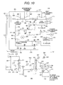
- the fossil fuel combustion thermal power system including the carbon dioxide separation and capture unit of the fifth embodiment of the present invention will be explained by referring to Figs. 10 and 11 .
- the fossil fuel combustion thermal power system including the carbon dioxide separation and capture unit of the fifth embodiment which is this embodiment is common in the basic constitution to the fossil fuel combustion thermal power system including the carbon dioxide separation and capture unit of the fourth embodiment explained previously. Therefore, the explanation of the constitution common to the two is omitted and only the different portions will be explained below.
- the fossil fuel combustion thermal power system including the carbon dioxide separation and capture unit of the fifth embodiment shown in Fig. 10 includes the fossil fuel combustion thermal power system 100 composing the steam turbine unit and the carbon dioxide separation and capture unit 200 for separating and capturing carbon dioxide from the boiler exhaust gas.
- a first back-pressure turbine entrance control valve 259 for controlling the flow-in steam quantity from the side of the second extraction pipe 254 to the back-pressure turbine 256 and a second back-pressure turbine entrance control valve 260 for controlling the flow-in steam quantity from the side of the back-pressure turbine blast pipe 255 to the back-pressure turbine 256 are installed.
- a back-pressure turbine exhaust pipe path 261 permitting the back-pressure turbine exhaust steam decompressed by driving the back-pressure turbine 256 to flow down
- a stop valve 262 installed in the back-pressure turbine exhaust pipe path 261
- the PCC unit blast pipe 241 connected to the back-pressure turbine exhaust pipe path 261 for sending the back-pressure turbine exhaust steam to the reboiler 225 and reclaimer 226 which are installed in the carbon dioxide separation and capture unit 200 which will be described later are installed.
- a second low-pressure turbine entrance pipe 263 including the stop valve 264 is connected to the second extraction pipe 254.
- the second low-pressure turbine entrance pipe 263 is connected to the second low-pressure turbine 242 and is structured so as to lead the steam flowing down in the second low-pressure turbine entrance pipe 263 to the second low-pressure turbine 242.
- a second condenser blast pipe 266 branching from the second low-pressure turbine entrance pipe 263 and interconnecting to the first condenser 209 is installed and in the second condenser blast pipe 266, a switching valve 267 is installed.
- the fossil fuel combustion thermal power system 100 includes a third extraction pipe 270 branching from the first extraction pipe 240 and interconnecting to the second low-pressure turbine entrance pipe 263 for leading the extraction steam flowing down in the first extraction pipe 240 to the second low-pressure turbine 242.
- a switching valve 271 for controlling switching of the flow path of the extraction steam to the side of the second low-pressure turbine is installed.
- the first extraction pipe 240 includes a first back-pressure turbine bypass pipe 272 branching on the downstream side of the condenser blast pipe 248 and the third extraction pipe 270, connecting to the PCC unit blast pipe 241 for permitting the extraction steam flowing down in the first extraction pipe 240 to bypass the back-pressure turbine 256 and leading it to the PCC unit blast pipe 241.
- the back-pressure turbine bypass pipe 272 includes a switching valve 273.
- the high-pressure turbine exhaust pipe 204 includes a second back-pressure turbine bypass pipe 274 branching on the downstream side of the second extraction pipe 254, connecting to the first back-pressure turbine bypass pipe 272, permitting the extraction steam of the high-pressure turbine to bypass the back-pressure turbine 256, and leading it to the reboiler 225 and reclaimer 226 of the carbon dioxide separation and capture unit 200 through the PCC unit blast pipe 241.
- the second back-pressure turbine bypass pipe 274 includes a switching valve 268 for controlling the extraction steam quantity bypassing the back-pressure turbine 256.
- Fig. 11 is a partial diagram showing the portion of the fossil fuel combustion thermal power system 100 of the fossil fuel combustion thermal power system including the carbon dioxide separation and capture unit of the fifth embodiment shown in Fig. 10 .
- a control unit 700 is installed and by the control unit 700, the operations of the second low-pressure turbine 242 and back-pressure turbine 256 are controlled.
- the steam turbine when the steam turbine is transferred from the rated load operation to the partial load operation, the steam pressure of the exhaust gas of the intermediate-pressure turbine 206 is lowered, and the exhaust steam cannot be sufficiently pumped to the back-pressure turbine 256, so that in place of the system of extracting steam from the intermediate-pressure turbine exhaust pipe 207 and supplying the intermediate-pressure turbine exhaust steam to the back-pressure turbine 256 through the first extraction pipe 240, back-pressure turbine blast pipe 255, and second back-pressure turbine entrance control valve 260, the system is switched to a system of supplying a part of the high-pressure steam flowing down in the high-pressure turbine exhaust pipe 204 from the high-pressure turbine 203 to the back-pressure turbine 256 through the second extraction pipe 254 and first back-pressure turbine entrance control valve 259, and the steam pressure necessary to drive the back-pressure turbine 256 is ensured.
- the control unit 700 when the steam turbine is in the partial load operation, the control unit 700 sends an instruction signal, opens the switching valve 257 installed in the second extraction pipe 254, leads the extraction steam of the high-pressure turbine 203 to the back-pressure turbine 256, adjusts the opening angle of the first back-pressure turbine entrance control valve 259, thereby controlling the flow rate, and drives and controls the back-pressure turbine 256 by the extraction steam from the high-pressure turbine 203.
- the steam turbine transfers from the partial load operation to the rated load operation, and the steam pressure flowing in the intermediate-pressure turbine exhaust pipe 207 is increased to a sufficient pressure to be pumped to the back-pressure turbine 256, and then the control unit 700 transmits the instruction signal, thus the switching valve 254 and first back-pressure turbine entrance control valve 259 are closed, and the switching valve 258 is opened, and the extraction steam of the intermediate-pressure turbine 206 is led to the back-pressure turbine 256, and the opening angle of the second back-pressure turbine entrance control valve 260 is adjusted, thus the flow rate is controlled, and by the steam extracted from the intermediate-pressure turbine exhaust steam, the back-pressure turbine 256 is driven and controlled.
- the back-pressure turbine exhaust steam after the back-pressure turbine 256 is driven is sent to the reboiler 225 and reclaimer 226 of the carbon dioxide separation and capture unit 200 through the back-pressure turbine exhaust pipe path 261 and the PCC unit blast pipe 241.
- the control unit 700 transmits an instruction signal and the switching valve 257 and the first back-pressure turbine entrance control valve 259 are closed. Further, the switching valve 268 is opened and the extraction steam is led to the PCC unit blast pipe 241 through the second back-pressure turbine bypass pipe 274 and first back-pressure turbine bypass pipe 272.
- a first blast pressure detector 275 installed on the back-pressure turbine blast pipe 255, the change of the pressure of the steam flowing down in the PCC unit blast pipe 241 is detected and when the detector 275 detects an abnormal change of the pressure, a trip signal is sent from the detector 275 to the control unit 700.
- the back-pressure turbine blast pipe 255 is not used and the first blast pressure detector 275 cannot be used. Therefore, when a second blast pressure detector 276 installed on the downstream side of the joining point of the PCC unit blast pipe 241 to the first back-pressure turbine bypass pipe 272 detects the pressure change of the supplied gas, and the detector 276 detects the abnormal change of the pressure, a trip signal is sent from the detector 276 to the control unit 700.
- the switching valves 257 and 268 are closed, and the switching valve 267 is opened simultaneously, and the extraction steam is led to and captured by the first condenser 209 through the second low-pressure turbine entrance pipe 263 and second condenser blast pipe 266. Thereafter, by the instruction signal from the control unit 700, the switching valve 267 is closed gradually, thus the opening angles of the stop valve 264 and the entrance control valve 243 of the second low-pressure turbine 242 are adjusted, and the supply destination of the extraction steam is controlled so as to be gradually switched to the second low-pressure turbine 242.
- the control unit 700 transmits an instruction signal, closes the switching valve 258, opens the switching valve 273, and leads the extraction steam to the PCC unit blast pipe 241 through the first back-pressure turbine bypass pipe 272.
- a trip signal is input to the control unit 700 from the enriched absorbing solution transfer pump 223, lean absorbing solution transfer pump 232, and detectors 275 and 276.
- control unit 700 receives the trip signal of the carbon dioxide separation and capture unit 200, by an instruction signal from the control unit 700, the switching valves 258 and 273 are closed, and the switching valve 249 is opened, and the surplus steam is captured once by the first condenser 209. Thereafter, by the instruction signal from the control unit 700, the switching valve 249 is closed gradually, thus the opening angles of the switching valve 271 and the entrance control valve 243 of the second low-pressure turbine 242 are adjusted, and the supply destination of the extraction steam is controlled so as to be gradually switched to the second low-pressure turbine 242.
- the control unit 700 when switching the flow path of the extraction steam to the first condenser 209 and second low-pressure turbine 242 through the third extraction pipe 270 and condenser blast pipe 248, the control unit 700, on the basis of a signal of the intermediate-pressure turbine exhaust pressure detector 252 for detecting the pressure change of the intermediate-pressure turbine exhaust steam, to prevent the intermediate-pressure turbine exhaust steam from excessively reducing in pressure beyond a predetermined set value due to switching of the flow path, controls the opening angles of the switching valve 249, the switching valve 271, and the entrance control valve 243 of the second low-pressure turbine 242.
- the intermediate-pressure turbine exhaust steam is extracted excessively by switching of the supply path, the intermediate-pressure turbine exhaust steam is excessively reduced in pressure and there is the possibility that a load exceeding the allowable quantity may be applied to the last stage blade of the intermediate-pressure turbine.
- the flow path switching control can be executed.
- the exhaust gas of the intermediate-pressure turbine 206 can be supplied to the back-pressure turbine 256 to generate electric power and during the partial load operation, the exhaust gas of the high-pressure turbine 203 can be supplied to the back-pressure turbine 256 to generate electric power.
- the back-pressure turbine 256 trips from some cause in the partial load operation and the rated load operation, the operation of the back-pressure turbine 256 is stopped, thus the extraction steam is permitted to bypass the back-pressure turbine 256, and thereby can be supplied to the side of the carbon dioxide separation and capture unit 200, and the carbon dioxide separation and capture unit can 200 be operated continuously.
- the surplus steam can be shifted to the second low-pressure turbine 242, and a sudden flow-in of steam exceeding the allowable quantity on the side of the low-pressure turbine (the first low-pressure turbine 208) of the steam turbine can be avoided, and the load change of the boiler 201 and steam turbine due to the surplus steam is suppressed, so that the stable operation of the fossil fuel combustion thermal power system 100 can be continued.
- the present invention can be applied to the fossil fuel combustion thermal power system including the carbon dioxide separation and capture unit.
Abstract
a back-pressure turbine (107) driven by extraction steam extracted from the high-pressure turbine (103) of the fossil fuel combustion thermal power system (100) through an extraction pipe (105); a reboiler (120) for supplying heating steam to the reproduction tower (123) of the carbon dioxide separation and capture unit (200); a steam pipe (110) for supplying steam flowing down through the back-pressure turbine (107) of the fossil fuel combustion thermal power system (100) to the reboiler (120) as a heat source.
Description
- The present invention relates to a fossil fuel combustion thermal power system including a carbon dioxide separation and capture unit.
- As a fossil fuel combustion thermal power system including a carbon dioxide separation and capture unit relating to the present invention, there is a system including a PCC unit (PCC: post combustion CO2 capture) for separating and capturing carbon dioxide from fossil fuel, for example, the exhaust gas of a coal combustion boiler.
- In Japanese Patent
4274846 - Generally, in the carbon dioxide separation and capture unit for capturing carbon dioxide from the exhaust gas of the boiler, the absorbing solution circulation pump is driven so as to circulate the absorbing solution between the absorption tower and the reproduction tower, and the carbon dioxide included in the exhaust gas of the boiler is absorbed by the absorbing solution in the absorption tower, and the carbon dioxide absorbed by the absorbing solution is separated and captured by the reproduction tower.
- Namely, the carbon dioxide component in the exhaust gas of the boiler and the absorbing solution are permitted to make contact with each other in the absorption tower, and by a chemical reaction (heat generation reaction) of the absorbing solution at about 40°C with the carbon dioxide in the gas, the carbon dioxide is absorbed.
- A carbon-dioxide-enriched absorbing solution at about 70°C due to the chemical reaction of the absorbing solution with the carbon dioxide at this time leaves the absorption tower, then exchanges heat with a reproduced absorbing solution (called a lean absorbing solution) at about 120°C supplied from the reproduction tower, is heated up to about 110°C, and flows again into the absorption tower.
- The enriched absorbing solution after heat exchange is heated again to 120°C to 130°C in the reproduction tower and separates the carbon dioxide absorbed by the enriched absorbing solution.
- The absorbing solution separating the carbon dioxide by the reproduction tower becomes a lean absorbing solution, is introduced again into the absorption tower, and absorbs carbon dioxide in the exhaust gas of the boiler.
- In this case, the absorbing solution in the reproduction tower is heated so as to separate the carbon dioxide and become the lean absorbing solution, so that the reboiler for supplying heating steam to the reproduction tower must generate a large quantity of steam.
- Patent Document 1: Japanese Patent No.
4274846 - In the carbon dioxide capture system described in Japanese Patent No.
4274846 - An object of the present invention is to provide a fossil fuel combustion thermal power system including a carbon dioxide separation and capture unit capable of suppressing a load change caused to the fossil fuel combustion thermal power system when the carbon dioxide separation and capture unit urgently stops the operation.
- The present invention of a fossil fuel combustion thermal power system including a carbon dioxide separation and capture unit comprising: a fossil fuel combustion thermal power system including a boiler for burning fossil fuel and generating steam and a steam turbine including a high-pressure turbine driven by the steam generated by the boiler for generating power, and a carbon dioxide separation and capture unit including an absorption tower for absorbing and capturing carbon dioxide included in the exhaust gas discharged from the boiler by burning fossil fuel in the boiler of the fossil fuel combustion thermal power system and a reproduction tower of an absorbing solution for separating carbon dioxide from the absorbing solution absorbing carbon dioxide by circulating the absorbing solution between the reproduction tower and the absorption tower,
the fossil fuel combustion thermal power system including the carbon dioxide separation and capture unit further comprising: a back-pressure turbine driven by extraction steam extracted from the high-pressure turbine of the fossil fuel combustion thermal power system through an extraction pipe; a reboiler for supplying heating steam to the reproduction tower of the carbon dioxide separation and capture unit; a steam pipe for supplying steam flowing down through the back-pressure turbine of the fossil fuel combustion thermal power system to the reboiler as a heat source; an emergency relief pipe interconnected to the extraction pipe for supplying the extraction steam extracted from the high-pressure turbine of the fossil fuel combustion thermal power system to the back-pressure turbine for permitting the extraction steam flowing down through the extraction pipe to bypass the back-pressure turbine and flow down to a condenser; and/or an emergency relief valve installed on the emergency relief pipe for controlling flow of the extraction steam through the emergency relief pipe. - Further, the present invention of a fossil fuel combustion thermal power system including a carbon dioxide separation and capture unit comprising: a fossil fuel combustion thermal power system including a boiler for burning fossil fuel and generating steam and a steam turbine including a high-pressure turbine and a intermediate-pressure turbine driven by the steam generated by the boiler for generating power, and a carbon dioxide separation and capture unit including an absorption tower for absorbing and capturing carbon dioxide included in the exhaust gas discharged from the boiler by burning fossil fuel in the boiler of the fossil fuel combustion thermal power system and a reproduction tower of an absorbing solution for separating carbon dioxide from the absorbing solution absorbing carbon dioxide by circulating the absorbing solution between the reproduction tower and the absorption tower,
the fossil fuel combustion thermal power system including'the carbon dioxide separation and capture unit further comprising: a reheat steam extraction pipe branching from a high-temperature reheat steam pipe for supplying reheat steam reheated by the boiler to the intermediate-pressure turbine from the boiler of the fossil fuel combustion thermal power system; a temperature lowering unit for lowering a temperature of the reheat steam extracted through the reheat steam extraction pipe; a back-pressure turbine driven by the reheat steam lowered in temperature by the temperature lowering unit; a reboiler for supplying heating steam to the reproduction tower of the carbon dioxide separation and capture unit; a steam pipe for supplying the steam flowing down through the back-pressure turbine of the fossil fuel combustion thermal power system to the reboiler as a heat source; a second emergency relief pipe interconnected to the reheat steam extraction pipe for supplying the reheat steam extracted through the reheat steam extraction pipe of the fossil fuel combustion thermal power system to the back-pressure turbine for permitting the reheat steam flowing down through the reheat steam extraction pipe to bypass the back-pressure turbine and flow down to a condenser; and/or a second emergency relief valve installed in the second emergency relief pipe for controlling flow of the reheat steam through the second emergency relief pipe. - Further, The present invention of a fossil fuel combustion thermal power system including a carbon dioxide separation and capture unit comprising: a fossil fuel combustion thermal power system including a boiler for burning fossil fuel and generating steam and a steam turbine including a high-pressure turbine and a intermediate-pressure turbine driven by the steam generated by the boiler for generating power, and a carbon dioxide separation and capture unit including an absorption tower for absorbing and capturing carbon dioxide included in the exhaust gas discharged from the boiler by burning fossil fuel in the boiler of the fossil fuel combustion thermal power system and a reproduction tower of an absorbing solution for separating carbon dioxide from the absorbing solution absorbing carbon dioxide by circulating the absorbing solution between the reproduction tower and the absorption tower,
the fossil fuel combustion thermal power system including the carbon dioxide separation and capture unit further comprising: a back-pressure turbine driven by the extraction steam extracted from the high-pressure turbine of the fossil fuel combustion thermal power system through a first extraction pipe; a second steam extraction pipe for branching a part of the exhaust steam of the intermediate-pressure turbine supplied from the intermediate-pressure turbine of the fossil fuel combustion thermal power system to a low-pressure turbine; a first steam pipe for supplying the extraction steam extracted through the second steam extraction pipe to the back-pressure turbine; a reboiler for supplying heating steam to the reproduction tower of the carbon dioxide separation and capture unit; a second steam pipe for supplying the steam flowing down through the back-pressure turbine of the fossil fuel combustion thermal power system to the reboiler as a heat source; a first emergency relief pipe interconnected to the first extraction pipe for supplying the extraction steam extracted from the high-pressure turbine of the fossil fuel combustion thermal power system to the back-pressure turbine for permitting the extraction steam flowing down through the first extraction pipe to bypass the back-pressure turbine and flow down to a condenser; a first emergency relief valve installed in the first emergency relief pipe for controlling flow of the extraction steam through the first emergency relief pipe; a third emergency relief pipe interconnected to the first steam pipe for supplying the extraction steam extracted through the second steam extraction pipe of the fossil fuel combustion thermal power system to the back-pressure turbine for permitting the extraction steam flowing down through the first steam pipe to bypass the back-pressure turbine and flow down to a condenser,and/or a third emergency relief valve installed in the third emergency relief pip for controlling flow of the reheat steam through the third emergency relief pipe. - According to the present invention, when an operation of the carbon dioxide separation and capture unit stops urgently, a fossil fuel combustion thermal power system including a carbon dioxide separation and capture unit capable of suppressing the load change of the fossil fuel combustion thermal power system can be realized.
-
-
Fig. 1 is a schematic flow diagram showing the fossil fuel combustion thermal power system including the carbon dioxide separation and capture unit of the first embodiment of the present invention, -
Fig. 2 is a partial diagram showing the fossil fuel combustion thermal power system of the first embodiment shown inFig. 1 , -
Fig. 3 is a steam I-S line diagram for explaining the expansion lines at the rated load and partial load of the steam turbine and back-pressure turbine of the fossil fuel combustion thermal power system of the embodiments of the present invention, -
Fig. 4 is a schematic flow diagram showing the fossil fuel combustion thermal power system including the carbon dioxide separation and capture unit of the second embodiment of the present invention, -
Fig. 5 is a partial diagram showing the fossil fuel combustion thermal power system of the second embodiment shown inFig. 4 , -
Fig. 6 is a schematic flow diagram showing the fossil fuel combustion thermal power system including the carbon dioxide separation and capture unit of the third embodiment of the present invention, and -
Fig. 7 is a partial diagram showing the fossil fuel combustion thermal power system of the third embodiment shown inFig. 6 . -
Fig. 8 is a schematic flow diagram showing the fossil fuel combustion thermal power system including the carbon dioxide separation and capture unit of the fourth embodiment of the present invention, and -
Fig. 9 is a partial diagram showing the fossil fuel combustion thermal power system of the fourth embodiment shown inFig. 8 . -
Fig. 10 is a schematic flow diagram showing the fossil fuel combustion thermal power system including the carbon dioxide separation and capture unit of the fifth embodiment of the present invention, and -
Fig. 11 is a partial diagram showing the fossil fuel combustion thermal power system of the fifth embodiment - The fossil fuel combustion thermal power system including the carbon dioxide separation and capture unit which is an embodiment of the present invention will be explained below with reference to the accompanying drawings.
- The fossil fuel combustion thermal power system including the carbon dioxide separation and capture unit of the first embodiment of the present invention will be explained by referring to
Figs. 1 and2 . -
Fig. 1 shows the fossil fuel combustion thermal power system including the carbon dioxide separation and capture unit of the first embodiment of the present invention. - A fossil fuel combustion
thermal power system 100 composing the fossil fuel combustion thermal power system including the carbon dioxide separation and capture unit of the first embodiment shown inFig. 1 includes a fossilfuel combustion boiler 101 for burning fossil fuel, heating condensed water supplied from a condenser, and generating steam at a high temperature and high pressure and a high-pressure turbine 103 for leading and driving the steam generated by theboiler 101 through amain steam pipe 102 from theboiler 101. - The steam decompressed due to an occurrence of power by the high-
pressure turbine 103 for flowing down through anexhaust pipe 104 of the high-pressure turbine is supplied to theboiler 101 through a low-temperaturereheat steam pipe 114 and is heated again by theboiler 101 to reheat the steam. - The system includes an intermediate-
pressure turbine 116 for leading and driving the reheat steam heated by theboiler 101 through a high-temperaturereheat steam pipe 115 from theboiler 101 and the steam reduced in pressure due to an occurrence of power by the intermediate-pressure turbine 116 for flowing down through anexhaust pipe 117 of the intermediate-pressure turbine from the intermediate-pressure turbine 116 is supplied to a low-pressure turbine 118 (not drawn). - By a
generator 180 driven by the high-pressure turbine 103, intermediate-pressure turbine 116, and low-pressure turbine 118, the output of the steam turbine is taken out as power. Further, thenumeral 175 indicates a deaerator. - In the fossil fuel combustion
thermal power system 100, afirst extraction pipe 105 branching from the low-temperaturereheat steam pipe 114 for supplying the steam flowing down through the high-temperatureturbine exhaust pipe 104 of the high-pressure turbine 103 to theboiler 101 for extracting a part of the steam flowing down through the low-temperaturereheat steam pipe 114 in order to drive the back-pressure turbine and a back-pressure turbine 107 driven by the steam extracted through thefirst extraction pipe 105 are installed. - On the entrance side of the back-
pressure turbine 107, a back-pressureturbine control valve 106 for controlling the output of the back-pressure turbine 107 is installed and on the exit side of the back-pressure turbine 107, an exhaust pipe path 108 (of the back-pressure turbine) for permitting the exhaust gas of the back-pressure turbine via the back-pressure turbine 107 to flow down, an exhaustpressure control valve 109 of the back-pressure turbine installed in theexhaust pipe path 108 of the back-pressure turbine for adjusting the pressure of the flowing exhaust gas of the back-pressure turbine, and anexit blast pipe 110 of the back-pressure turbine interconnected to theexhaust pipe path 108 of the back-pressure turbine for sending the exhaust gas of the back-pressure turbine to areboiler 120 and areclaimer 121 which are installed in a carbon dioxide separation andcapture unit 200 which will be described later are installed. - On the back-
pressure turbine 107, a back-pressure turbine generator 113 is installed and it is structured so as to take out the power of the back-pressure turbine 107 as electric power. - To the low-temperature
reheat steam pipe 114 through which the steam flowing down in the high-pressure turbine 103 through theexhaust pipe 104 of the high-pressure turbine and supplied to theboiler 101 flows, a firstemergency relief pipe 112 including a firstemergency relief valve 111 is interconnected. - And, when the back-
pressure turbine 107 stops operation by some cause, the extraction steam which flows down in the high-pressure turbine 103 through thefirst extraction pipe 105 branching from the low-temperaturereheat steam pipe 114 and is supplied to the back-pressure turbine 107 is structured so as to open the firstemergency relief valve 111 installed in the firstemergency relief pipe 112 and flow down into the condenser through the firstemergency relief pipe 112. - In the fossil fuel combustion thermal power system including the carbon dioxide separation and capture unit of the first embodiment shown in
Fig. 1 , the fossil fuel combustionthermal power system 100 and the carbon dioxide separation andcapture unit 200 for separating and capturing the carbon dioxide included in the exhaust gas of the boiler discharged from theboiler 101 of the fossil fuel combustionthermal power system 100 by burning fossil fuel are installed. - In the carbon dioxide separation and
capture unit 200 shown inFig. 1 , the boiler exhaust gas including carbon dioxide which is discharged from theboiler 101 and is branched and supplied from a boiler exhaustgas system pipe 171 flows down through a boilerexhaust gas pipe 140, is boosted by a boiler exhaustgas boost fan 141 installed in the boilerexhaust gas pipe 140, then is supplied to and cooled by a boilerexhaust gas cooler 142, and is supplied to anabsorption tower 126 for absorbing carbon dioxide gas from the boilerexhaust gas cooler 142 by the absorbing solution. - The carbon dioxide gas included in the boiler exhaust gas is absorbed by the absorbing solution in the
absorption tower 126 and the processed gas which is boiler exhaust gas including no carbon dioxide is supplied to achimney 146 from theabsorption tower 126 through an exit boilerexhaust gas pipe 145 of the absorption tower and is discharged from thechimney 146 into the atmosphere. - Further, among the boiler exhaust gas including carbon dioxide supplied from the
boiler 101 through the boiler exhaustgas system pipe 171, the boiler exhaust gas not supplied to theabsorption tower 126, by a valve opening operation of abypass butterfly valve 143 installed on abypass gas pipe 144 for bypassing the carbon dioxide separation andcapture unit 200, is directly led to thechimney 146 through thebypass gas pipe 144. - The enriched absorbing solution absorbing carbon dioxide gas included in the boiler exhaust gas supplied from the
boiler 101 in theabsorption tower 126 and including much carbon dioxide is boosted by an enriched absorbingsolution transfer pump 127 installed in the supply path of the absorbing solution for supplying the absorbing solution of theabsorption tower 126 to areproduction tower 123, is supplied to an absorbingsolution heat exchanger 128 similarly installed in the supply path of the absorbing solution, is heated by the absorbingsolution heat exchanger 128, and then is supplied to thereproduction tower 123. - The enriched absorbing solution supplied from the
absorption tower 126 to thereproduction tower 123 is heated by supplying vapor generated by being heated by the back-pressure turbine exhaust steam supplied to thereboiler 120 andreclaimer 121 as a heat source to thereproduction tower 123 from thereboiler 120 andreclaimer 121 and the carbon oxide gas absorbed by the enriched absorbing solution in thereproduction tower 123 is separated from the enriched absorbing solution. - By heating by the vapor supplied from the
reboiler 120, the carbon dioxide separated from the enriched absorbing solution in thereproduction tower 123 is discharged from thereproduction tower 123, though it is cooled by anexit gas cooler 131 installed on the exit side of thereproduction tower 123 and then is supplied to areflux drum 132 for separating moisture, and the moisture included in the carbon dioxide gas is separated, and only the carbon oxide gas is supplied to and stored in a carbon dioxide liquefying and storing facility (not drawn) from thereflux drum 132 through a carbon dioxidegas exhaust pipe 147. - Further, the moisture separated by the
reflux drum 132 is structured so as to be boosted by areflux drum pump 133 and be returned to thereproduction tower 123. - And, a part of the absorbing solution in the
reproduction tower 123 is pulled out through an absorbing solution pull-outpipe 124 in the reproduction tower and is branched and supplied to thereboiler 120 andreclaimer 121 and it is heated by thereboiler 120 to which the back-pressure turbine exhaust steam flowing down through the back-pressure turbine 107 driven by the heating steam extracted from the steam turbine cycle of the fossil fuel combustionthermal power system 100, that is, the extraction steam extracted from the high-pressure turbine 103 is supplied as a heat source. - Further, the
reclaimer 121 is a cleaning unit of the absorbing solution for heating the absorbing solution by using the back-pressure turbine exhaust steam flowing down through the back-pressure turbine 107 as a heat source, separating impurities included in the absorbing solution, and discharging them out of the system. - The heating steam necessary to heat the
reboiler 120 andreclaimer 121 is obtained by sending the back-pressure turbine exhaust steam flowing down through the back-pressure turbine 107 composing the fossil fuel combustionthermal power system 100 to thereboiler 120 and reclaimer 121 through the back-pressureturbine exhaust pipe 110. - The absorbing solution separating carbon dioxide by heating the absorbing solution in the
reproduction tower 123 is boosted by a lean absorbingsolution transfer pump 129 installed in the return path of the absorbing solution for returning the absorbing solution from thereproduction tower 123 to theabsorption tower 126, is supplied to a lean absorbingsolution cooler 130 similarly installed in the return path of the absorbing solution, is cooled by the lean absorbingsolution cooler 130, and then is returned to theabsorption tower 126, thus the absorbing solution is circulated between theabsorption tower 126 and thereproduction tower 123. - And, the system is structured so as to supply the back-pressure turbine exhaust steam flowing down from the back-
pressure turbine 107 through the back-pressureturbine exhaust pipe 110 to thereboiler 120 and reclaimer 121 as a heat source, indirectly heat the absorbing solution pulled out from thereproduction tower 123 through the absorbing solution pull-outpipe 124 in the reproduction tower by thereboiler 120, generate clean steam at a desired temperature and pressure, and supply the generated steam to thereproduction tower 123 through asteam pipe 125 at the reboiler exit. - On the
exit blast pipe 110 of the back-pressure turbine on the upstream side of thereboiler 120 andreclaimer 121, a reboiler heating steampressure control valve 134 and a reclaimer heating steampressure control valve 135 are installed, thus the flow rate of the back-pressure turbine exhaust steam supplied to thereboiler 120 is adjusted so as to control the steam generated by thereboiler 120 to a desired temperature and pressure. - Further, on the downstream side of the
reboiler 120 andreclaimer 121, a boiler and a reclaimer heatingsteam drain pipe 122 for leading the back-pressure turbine exhaust steam which is used by thereboiler 120 andreclaimer 121 as a heat source and is lowered in temperature to the drain capture system of the turbine condensate system are arranged. -
Fig. 2 is a partial diagram showing the portion of the fossil fuel combustionthermal power system 100 of the fossil fuel combustion thermal power system including the carbon dioxide separation and capture unit of the first embodiment shown inFig. 1 . - In the fossil fuel combustion
thermal power system 100 of this embodiment shown inFig. 2 , the firstemergency relief pipe 112 including the firstemergency relief valve 111 interconnected to the low-temperaturereheat steam pipe 114 through which the steam flowing down from the high-pressure turbine 103 through theexhaust pipe 104 of the high-pressure turbine flows for permitting the steam flowing into the low-temperaturereheat steam pipe 114 to bypass the back-pressure turbine 107 and to be discharged to a condenser (not shown) is arranged. - Further, there is a
control unit 300 installed and by theturbine control unit 300, the operation of the back-pressure turbine 107 is controlled. - Namely, by an instruction signal of the
control unit 300, the opening angle of a first back-pressureturbine control valve 106 is adjusted and the flow rate of steam supplied to the back-pressure turbine 107 is controlled. Further, by the instruction signal of thecontrol unit 300, the opening angle of a back-pressure turbine exhaustpressure regulating valve 109 is adjusted and the pressure of the back-pressure turbine exhaust steam which flows down in the back-pressure turbine 107, flows in theexit blast pipe 110 of the back-pressure turbine on the downstream side of the back-pressure turbine exhaustpressure regulating valve 109, and is supplied to thereboiler 120 is controlled. - On the other hand, when the main unit of the carbon dioxide separation and
capture unit 200 trips by some cause, for example, when the enriched absorbingsolution transfer pump 127 for transferring the absorbing solution or the lean absorbing solution transfer pump 129 trips and the operation of the carbon dioxide separation andcapture unit 200 stops urgently, the surplus steam (in the normal operation, from the back-pressure turbine 107 to thereboiler 120, the back-pressure turbine exhaust steam flowing down in the back-pressure turbine 107 is supplied as a heat source) supplied from the fossil fuel combustionthermal power system 100 to the carbon dioxide separation andcapture unit 200 is permitted to bypass the back-pressure turbine 107 and to shift to the condenser through the firstemergency relief pipe 112 including the firstemergency relief valve 111. - The steam quantity required by the
reboiler 120 is far larger than the steam quantity required by thereclaimer 121 and is equivalent to about 15% to 20% of the total quantity of evaporation of the boiler. Therefore, at the time of urgent stop of the carbon dioxide separation andcapture unit 200, in response to an urgent reduction of the steam quantity supplied to thereboiler 120, the urgent relief system composed of the firstemergency relief pipe 112 including the firstemergency relief valve 111 for permitting the surplus steam to flow down into the condenser can effectively fulfill the surplus steam urgent relief function. - In the fossil fuel combustion
thermal power system 100 shown inFig. 2 , thecontrol unit 300 for controlling the operation of the back-pressure turbine 107 and the operation of the firstemergency relief valve 111 installed in the firstemergency relief pipe 112 for shifting the surplus steam to the condenser at the time of urgent stop of the carbon dioxide separation andcapture unit 200 is installed. - And, when the enriched absorbing
solution transfer pump 127 which is a main unit of the carbon dioxide separation andcapture unit 200 or the lean absorbing solution transfer pump 129 trips, and the operation of the carbon dioxide separation andcapture unit 200 stops urgently, and the steam supplied from the steam turbine cycle of the fossil fuel combustionthermal power system 100 to thereboiler 120 is required to stop immediately, on the basis of atrip signal 127a of the enriched absorbingsolution transfer pump 127 or atrip signal 129a of the lean absorbingsolution transfer pump 129 which are input from the sensors respectively installed in the enriched absorbingsolution transfer pump 127 and the lean absorbingsolution transfer pump 129, the urgent stop of the carbon dioxide separation andcapture unit 200 is detected by thecontrol unit 300, and to stop the operation of the back-pressure turbine 107, the first back-pressureturbine control valve 106 installed on the entrance side of the back-pressure turbine 107 is completely closed by the instruction signal from thecontrol unit 300, and the steam flowing into the back-pressure turbine 107 is interrupted. - And, simultaneously, by the instruction signal from the
control unit 300, the firstemergency relief valve 111 is opened, and the surplus steam flowing in the back-pressure turbine 107 through the low-temperaturereheat steam pipe 114 is switched so as to bypass the back-pressure turbine 107 through the firstemergency relief pipe 112 interconnected to the low-temperaturereheat steam pipe 114 and flow down into the condenser. - The aforementioned control operation is performed under the control of the
control unit 300, thus the load change of theboiler 101 and steam turbine due to the surplus steam caused by the urgent stop of the carbon dioxide separation andcapture unit 200 is suppressed, so that even at the time of urgent stop of the carbon dioxide separation andcapture unit 200, the stable operation of the fossil fuel combustionthermal power system 100 can be continued. - The surplus steam flowing down to the condenser, thereafter, is operated so as to adjust the opening angle of the first
emergency relief valve 111 and decrease the flow rate. - Thereafter, in accordance with the flow rate reduction operation of the surplus steam flowing down to the condenser via the first
emergency relief pipe 112 by thecontrol unit 300, an operation of reducing the quantity of evaporation of the vapor generated in theboiler 101 in response to the reduction in the steam quantity supplied to thereboiler 120 of the carbon dioxide separation andcapture unit 200 from the fossil fuel combustionthermal power system 100 is also transferred. - On the other hand, the fossil fuel combustion
thermal power system 100 and the carbon dioxide separation andcapture unit 200 are generally installed away from each other, so that the length of theexit blast pipe 110 of the back-pressure turbine for supplying the back-pressure turbine exhaust steam of the back-pressure turbine 107 to thereboiler 120 is increased. Further, the steam quantity of the back-pressure turbine exhaust steam is large and the pipe aperture is also large, so that the storage of steam in theexit blast pipe 110 of the back-pressure turbine cannot be ignored. - Therefore, in this embodiment, at the position of the
exit blast pipe 110 of the back-pressure turbine on the upstream side in the vicinity of thereboiler 120 orreclaimer 121 of the carbon dioxide separation andcapture unit 200, the reboiler entrancepressure regulating valve 134 and reclaimer entrancepressure regulating valve 135 are respectively installed on theexit blast pipe 110 of the back-pressure turbine, and can thereby respond by adjusting the opening angles of the reboiler entrancepressure regulating valve 134 and reclaimer entrancepressure regulating valve 135 by a control signal from thecontrol unit 300. -
Fig. 3 , with respect to the steam turbine including the high-pressure steam turbine 103, intermediate-pressure turbine 116, and low-pressure turbine 118 composing the fossil fuel combustion thermal power system including the carbon dioxide separation and capture unit of the first embodiment of the present invention, shows the steam I-S line diagram (steam enthalpy I - steam entropy S line diagram), wherein the turbine steam expansion lines indicating respectively the expansion line at the rated load of a load of 100% with a thick solid line and the expansion line at the partial load of a load of 50% with a thick alternate long and short dash line and the expansion lines indicating respectively those at the rated load and partial load of the back-pressure turbine 107 with thick dashed lines are described. - As shown in the steam I-S line diagram in
Fig. 3 , for the extraction steam supplied to the back-pressure turbine 107 through thefirst extraction pipe 105 branched from the low-temperaturereheat steam pipe 114 through which the steam flowing down in the high-pressure turbine 103 of the steam turbine and supplied to theboiler 101 flows, the flow rate thereof is adjusted by the operation of the first back-pressureturbine control valve 106, thus the output of the back-pressure turbine 107 is controlled. - And, the exhaust pressure of the back-
pressure turbine 107 is set to a pressure of about 0.5 MPa which is necessary to generate vapor at a desired temperature and pressure by thereboiler 120 installed in the carbon dioxide separation andcapture unit 200 in consideration of a pressure loss of about 0.1 MPa by the pipe and valve, thus the pressure of the back-pressure turbine exhaust steam is adjusted to about 0.6 MPa. - The locus of the expansion line of the back-
pressure turbine 107 under this condition is indicated by a thick dashed line in the steam I-S line diagram shown inFig. 3 . - The steam expanding and working in the back-
pressure turbine 107 and flowing down in the back-pressure turbine 107 passes through the back-pressureturbine exhaust pipe 108 and the back-pressure turbine exhaustpressure regulating valve 109 and is supplied to thereboiler 120 orreclaimer 121 of the carbon dioxide separation andcapture unit 200 as a heat source through the back-pressureturbine exhaust pipe 110. - And, in the fossil fuel combustion thermal power system including the carbon dioxide separation and capture unit of the first embodiment, as shown in the steam I-S line diagram in
Fig. 3 , if the steam turbine transfers from the rated main steam pressure (25 MPa) of the rated load operation, for example, to the partial load operation of a load of 50%, the main steam pressure is reduced from the rated main steam pressure (25 MPa) to the 50%-load steam pressure (12.5 MPa), though the main steam temperature is kept almost constant even if the rated load operation is changed to the partial load operation. - In correspondence with the reduction in the main steam pressure aforementioned, the pressure of the steam which flows down in the high-
pressure turbine 103 through the high-pressureturbine exhaust pipe 104 in the partial load operation and is supplied to the low-temperaturereheat steam pipe 114 lowers, though the steam supplied to the low-temperaturereheat steam pipe 114 shows the situation that the steam under the condition of a pressure of about 0.5 MPa and a temperature of about 170°C required by thereboiler 120 of the carbon dioxide separation andcapture unit 200 to generate steam is sufficiently ensured. - Simultaneously, the steam flowing down in the
exit blast pipe 110 of the back-pressure turbine from the low-temperaturereheat steam pipe 114 via the back-pressure turbine 107 and reaching thereboiler 120 is sufficiently away from the steam saturation line indicated by a thin line on the lower part ofFig. 3 and the situation that the fault that the steam is drained during flowing from the back-pressure turbine 107 to theexit blast pipe 110 of the back-pressure turbine is avoided is indicated. - According to the embodiment of the present invention aforementioned, when the carbon dioxide separation and capture unit stops urgently, a fossil fuel combustion thermal power system including a carbon dioxide separation and capture unit capable of suppressing the load change of the fossil fuel combustion thermal power system can be realized.
- The fossil fuel combustion thermal power system including the carbon dioxide separation and capture unit of the second embodiment of the present invention will be explained by referring to
Figs. 4 and5 . - The fossil fuel combustion thermal power system including the carbon dioxide separation and capture unit of the second embodiment which is this embodiment is common in the basic constitution to the fossil fuel combustion thermal power system including the carbon dioxide separation and capture unit of the first embodiment explained previously. Therefore, the explanation of the constitution common to the two is omitted and only the different portions will be explained below.
- The fossil fuel combustion thermal power system including the carbon dioxide separation and capture unit of the second embodiment shown in
Fig. 4 includes the fossil fuel combustionthermal power system 100 composing the steam turbine heat cycle and the carbon dioxide separation andcapture unit 200 for separating and capturing carbon dioxide from the boiler exhaust gas. - The fossil fuel combustion
thermal power system 100 is structured so as to extract a part of high-temperature reheat steam through a high-temperature reheatsteam extraction pipe 150 branching from the middle of the high-temperaturereheat steam pipe 115 for supplying the high-temperature reheat steam from theboiler 101 to the intermediate-pressure turbine 116 and supply the extracted high-temperature reheat steam to a high-temperature reheat steam extractiontemperature lowering unit 151. - In the high-temperature reheat steam extraction
temperature lowering unit 151, separately, the high-temperature reheat steam is lowered in temperature by cold water led via a high-temperature reheat steam extraction temperature loweringunit spray valve 152, then is supplied through asecond extraction pipe 153 arranged on the exit side of thetemperature lowering unit 151, and is introduced to the back-pressure turbine 107 from a second back-pressureturbine control valve 154. - The reheat steam introduced to the back-
pressure turbine 107 through the high-temperature reheatsteam extraction pipe 150 expands and works in the back-pressure turbine 107 and contributes to power generation. And, the steam after flowing down in the back-pressure turbine 107 is structured so as to pass through the back-pressure turbineexhaust pipe path 108 and the back-pressure turbine exhaustpressure regulating valve 109 from the back-pressure turbine 107 and to be supplied to thereboiler 120 orreclaimer 121 installed in the carbon dioxide separation andcapture unit 200 as a heat source through the back-pressureturbine exhaust pipe 110. - On the other hand, in the fossil fuel combustion
thermal power system 100, if the steam turbine transfers to an operation of reducing the load from the rated load operation to the partial load operation, even though the high-temperature reheat steam pressure of the reheat steam supplied to the intermediate-pressure turbine 116 from theboiler 101 through the high-temperaturereheat steam pipe 115 is reduced, the high-temperature reheat steam temperature is kept almost constant even if the rated load operation is changed to the partial load operation. - And, when the steam turbine of the fossil fuel combustion
thermal power system 100 is transferred from the rated load operation to the partial load operation, a part of the high-temperature reheat steam supplied from theboiler 101 to the intermediate-pressure turbine 116 is branched from the high-temperaturereheat steam pipe 115 and is supplied to the high-temperature reheat steam extractiontemperature lowering unit 151 through the high-temperature reheatsteam extraction pipe 150. - And, the high-temperature reheat steam extraction
temperature lowering unit 151 is structured so as to separately lower the temperature of the high-temperature reheat steam by cold water led from the high-temperature reheat steam extraction temperature loweringunit spray valve 152 down to the temperature required by thereboiler 120 orreclaimer 121 of the carbon dioxide separation andcapture unit 200 as a heat source which will be described later and to introduce the reheat steam lowered in temperature to the back-pressure turbine 107 via thesecond extraction pipe 153 and second back-pressureturbine control valve 154. - Further, that the system is structured so as to supply the back-pressure turbine exhaust steam flowing down from the back-
pressure turbine 107 to thereboiler 120 andreclaimer 121 installed in the carbon dioxide separation andcapture unit 200 as a heat source, indirectly heat the absorbing solution pulled out from thereproduction tower 123 through the absorbing solution pull-outpipe 124 in the reproduction tower by thereboiler 120 andreclaimer 121, generate clean steam at a desired temperature and pressure, and supply the generated steam to thereproduction tower 123 through thesteam pipe 125 at the reboiler exit is similar to the fossil fuel combustion thermal power system including the carbon dioxide separation and capture unit of the first embodiment, so the explanation of the carbon dioxide separation andcapture unit 200 will be omitted. -
Fig. 5 is a partial diagram showing the portion of the fossil fuel combustionthermal power system 100 of the fossil fuel combustion thermal power system including the carbon dioxide separation and capture unit of the second embodiment shown inFig. 4 . - In the fossil fuel combustion
thermal power system 100 of this embodiment shown inFig. 5 , a secondemergency relief pipe 156 including a secondemergency relief valve 155 interconnected to thesecond extraction pipe 153 for permitting the steam flowing in thesecond extraction pipe 153 to bypass the back-pressure turbine 107 and discharge it to a condenser (not drawn) is arranged. - In the fossil fuel combustion thermal power system including the carbon dioxide separation and capture unit having the aforementioned constitution, the high-temperature reheat steam can be supplied to the
reboiler 120 of the carbon dioxide separation and capture unit, so that the temperature of the absorbing solution in thereproduction tower 123 can be raised higher. - When the main unit of the carbon dioxide separation and
capture unit 200 trips from some cause, for example, when the enriched absorbingsolution transfer pump 127 for transferring the absorbing solution or the lean absorbing solution transfer pump 129 trips and the operation of the carbon dioxide separation andcapture unit 200 stops urgently, the surplus steam (in the normal operation, from the back-pressure turbine 107 to thereboiler 120, the back-pressure turbine exhaust steam flowing down in the back-pressure turbine 107 is supplied as a heat source) supplied from the fossil fuel combustionthermal power system 100 to the carbon dioxide separation andcapture unit 200 is permitted to bypass the back-pressure turbine 107 and to shift to the condenser through the secondemergency relief pipe 156 including the secondemergency relief valve 155. - In the fossil fuel combustion
thermal power system 100 shown inFig. 5 , acontrol unit 400 for controlling the operation of the back-pressure turbine 107 and the operation of the secondemergency relief valve 155 installed in the secondemergency relief pipe 156 for shifting the surplus steam to the condenser at the time of an urgent stop of the carbon dioxide separation andcapture unit 200 is installed. - And, when the enriched absorbing
solution transfer pump 127 or the lean absorbingsolution transfer pump 129 which are main units of the carbon dioxide separation andcapture unit 200 trips, and the operation of the carbon dioxide separation andcapture unit 200 stops urgently, and the steam supplied from the steam turbine cycle of the fossil fuel combustionthermal power system 100 to thereboiler 120 is required to stop immediately, on the basis of atrip signal 127a of the enriched absorbingsolution transfer pump 127 or atrip signal 129a of the lean absorbingsolution transfer pump 129 which are input from the sensors respectively installed in the enriched absorbingsolution transfer pump 127 and the lean absorbingsolution transfer pump 129, the urgent stop of the carbon dioxide separation andcapture unit 200 is detected by thecontrol unit 400, and to stop the operation of the back-pressure turbine 107, the second back-pressureturbine control valve 154 installed on the entrance side of the back-pressure turbine 107 is completely closed by the instruction signal from thecontrol unit 400, and the steam flowing into the back-pressure turbine 107 is interrupted. - And, simultaneously, by the instruction signal from the
control unit 400, the secondemergency relief valve 155 is opened, and the surplus steam flowing in the back-pressure turbine 107 through thesecond extraction pipe 153 is switched so as to bypass the back-pressure turbine 107 through the secondemergency relief pipe 156 interconnected to thesecond extraction pipe 153 and flow down into the condenser. - The aforementioned control operation is performed under the control of the
control unit 400, thus the load change of theboiler 101 and steam turbine due to the surplus steam caused by the urgent stop of the carbon dioxide separation andcapture unit 200 is suppressed, so that even at the time of urgent stop of the carbon dioxide separation andcapture unit 200, the stable operation of the fossil fuel combustionthermal power system 100 can be continued. - The surplus steam flowing down to the condenser, thereafter, is operated so as to adjust the opening angle of the second
emergency relief valve 155 and decrease the flow rate. - Thereafter, in accordance with the flow rate reduction operation of the surplus steam flowing down to the condenser via the second
emergency relief pipe 156 by thecontrol unit 400, an operation of reducing the quantity of evaporation of the vapor generated in theboiler 101 in response to the reduction in the steam quantity supplied to thereboiler 120 of the carbon dioxide separation andcapture unit 200 from the fossil fuel combustionthermal power system 100 is also transferred. - According to the embodiment of the present invention aforementioned, when the carbon dioxide separation and capture unit stops urgently, a fossil fuel combustion thermal power system including a carbon dioxide separation and capture unit capable of suppressing the load change of the fossil fuel combustion thermal power system can be realized.
- The fossil fuel combustion thermal power system including the carbon dioxide separation and capture unit of the third embodiment of the present invention will be explained by referring to
Fig. 6 . - The fossil fuel combustion thermal power system including the carbon dioxide separation and capture unit of the third embodiment which is this embodiment is common in the basic constitution to the fossil fuel combustion thermal power system including the carbon dioxide separation and capture unit of the first embodiment explained previously. Therefore, the explanation of the constitution common to the two is omitted and only the different portions will be explained below.
- The fossil fuel combustion thermal power system including the carbon dioxide separation and capture unit shown in
Fig. 6 includes the fossil fuel combustionthermal power system 100 composing the steam turbine heat cycle and the carbon dioxide separation andcapture unit 200 for separating and capturing carbon dioxide from the boiler exhaust gas. - In the fossil fuel combustion
thermal power system 100, thefirst extraction pipe 105 branching from the low-temperaturereheat steam pipe 114 for supplying the steam flowing down through the high-temperatureturbine exhaust pipe 104 of the high-pressure turbine 103 to theboiler 101 for extracting a part of the steam flowing down through the low-temperaturereheat steam pipe 114 in order to drive the back-pressure turbine and the back-pressure turbine 107 driven by the steam extracted through thefirst extraction pipe 105 are installed and on the entrance side of the back-pressure turbine 107, the back-pressureturbine control valve 106 for controlling the output of the back-pressure turbine 107 is installed. - Furthermore, the system is structured so that a part of the steam which flows down through the intermediate-
pressure turbine 116 and is supplied from the intermediate-pressureturbine exhaust pipe 117 to the low-temperature turbine 118 (not drawn) is extracted through a intermediate-pressure turbine exhaustportion extraction pipe 160 and the extracted steam through athird extraction pipe 161 at the entrance of the back-pressure turbine interconnected to the intermediate-pressure turbine exhaustportion extraction pipe 160 is introduced to the back-pressure turbine 107 via a second back-pressureturbine control valve 162 installed on the entrance side of the back-pressure turbine 107. - In the fossil fuel combustion
thermal power system 100 of this embodiment shown inFig. 7 , the firstemergency relief pipe 112 including the firstemergency relief valve 111 interconnected to the low-temperaturereheat steam pipe 114 through which the steam flowing down from the high-pressure turbine 103 through theexhaust pipe 104 of the high-pressure turbine flows for permitting the steam flowing into the low-temperaturereheat steam pipe 114 to bypass the back-pressure turbine 107 and to be discharged to a condenser (not shown) is arranged. - Furthermore, in the
third extraction pipe 161 at the entrance of the back-pressure turbine, a thirdemergency relief pipe 164 for shifting the extraction steam flowing down in thethird extraction pipe 161 at the entrance of the back-pressure turbine to the condenser is arranged and a thirdemergency relief valve 163 for controlling the down-flow of the steam is arranged on the thirdemergency relief pipe 164. - Further, the carbon dioxide separation and
capture unit 200 is similar to that of the first embodiment, so the explanation is omitted. - In the fossil fuel combustion
thermal power system 100, when the steam turbine transfers from the rated load operation to the partial load operation, the steam pressure of the exhaust steam of the intermediate-pressure turbine 116 is reduced, so that a system of extracting steam from the intermediate-pressureturbine exhaust pipe 117 and supplying the intermediate-pressure turbine exhaust steam to the back-pressure turbine 107 through the intermediate-pressure turbine exhaustportion extraction pipe 160, thethird extraction pipe 161 at the entrance of the back-pressure turbine, and the second back-pressureturbine control valve 162 is switched, and a system of supplying the high-pressure steam flowing down into the low-temperaturereheat steam pipe 114 from the high-pressure turbine 103 to the back-pressure turbine 107 through thefirst extraction pipe 105 and the back-pressureturbine control valve 106 is switched, thus the steam pressure necessary to drive the back-pressure turbine 107 is ensured. - In the fossil fuel combustion thermal power system including the carbon dioxide separation and capture unit having the aforementioned constitution, during the rated load operation, the exhaust steam of the intermediate-
pressure turbine 116 can be supplied to the back-pressure turbine 107, so that compared with the constitution of supplying only the exhaust steam of the high-pressure turbine 103 to the back-pressure turbine 107, the output reduction of the steam turbine can be suppressed effectively. - When the main unit of the carbon dioxide separation and
capture unit 200 trips from some causes, for example, when the enriched absorbingsolution transfer pump 127 or the lean absorbingsolution transfer pump 129 for transferring the absorbing solution trips and the operation of the carbon dioxide separation andcapture unit 200 stops urgently, the surplus steam (in the normal operation, from the back-pressure turbine 107 to thereboiler 120, the back-pressure turbine exhaust steam flowing down in the back-pressure turbine 107 is supplied as a heat source) supplied from the fossil fuel combustionthermal power system 100 to the carbon dioxide separation andcapture unit 200 is permitted to bypass the back-pressure turbine 107 and to shift to the condenser through the firstemergency relief pipe 112 including the firstemergency relief valve 111 or to shift to the condenser through the thirdemergency relief pipe 164 including the thirdemergency relief valve 163. - In the fossil fuel combustion
thermal power system 100 shown inFig. 7 , acontrol unit 500 for controlling the operation of the back-pressure turbine 107, the operation of the firstemergency relief valve 111 installed in the firstemergency relief pipe 112 for shifting the surplus steam to the condenser at the time of an urgent stop of the carbon dioxide separation andcapture unit 200, and the operation of the thirdemergency relief valve 163 installed in the thirdemergency relief pipe 164 is installed. - And, when the enriched absorbing
solution transfer pump 127 or the lean absorbingsolution transfer pump 129 which are main units of the carbon dioxide separation andcapture unit 200 trips, and the operation of the carbon dioxide separation andcapture unit 200 stops urgently, and the steam supplied from the steam turbine cycle of the fossil fuel combustionthermal power system 100 to thereboiler 120 is required to stop immediately, on the basis of atrip signal 127a of the enriched absorbingsolution transfer pump 127 or atrip signal 129a of the lean absorbingsolution transfer pump 129 which are input from the sensors respectively installed in the enriched absorbingsolution transfer pump 127 and the lean absorbingsolution transfer pump 129, the urgent stop of the carbon dioxide separation andcapture unit 200 is detected by thecontrol unit 500, and to stop the operation of the back-pressure turbine 107, the first back-pressureturbine control valve 106 installed on the entrance side of the back-pressure turbine 107 is completely closed by the instruction signal from thecontrol unit 500, and the steam flowing into the back-pressure turbine 107 is interrupted. - And, simultaneously, when the steam turbine of the fossil fuel combustion
thermal power system 100 is in the rated load operation, by the instruction signal from thecontrol unit 500, the thirdemergency relief valve 163 is opened, and the surplus steam flowing in the back-pressure turbine 107 through the intermediate-pressure turbine exhaustportion extraction pipe 160 is switched so as to bypass the back-pressure turbine 107 through the thirdemergency relief pipe 164 interconnected to the intermediate-pressure turbine exhaustportion extraction pipe 160 and flow down into the condenser. - Further, when the steam turbine of the fossil fuel combustion
thermal power system 100 is in the partial load operation, by the instruction signal from thecontrol unit 500, the firstemergency relief valve 111 is opened, and the surplus steam flowing in the back-pressure turbine 107 through the low-temperaturereheat steam pipe 114 is switched so as to bypass the back-pressure turbine 107 through the firstemergency relief pipe 112 interconnected to the low-temperaturereheat steam pipe 114 and flow down into the condenser. - The aforementioned control operation is performed under the control of the
control unit 500, thus the load change of theboiler 101 and steam turbine due to the surplus steam caused by the urgent stop of the carbon dioxide separation andcapture unit 200 is suppressed, so that even at the time of urgent stop of the carbon dioxide separation andcapture unit 200, the stable operation of the fossil fuel combustionthermal power system 100 can be continued. - The surplus steam flowing down to the condenser, thereafter, is operated so as to adjust the opening angle of the first
emergency relief valve 111 or the thirdemergency relief valve 163 and decrease the flow rate. - Thereafter, in accordance with the flow rate reduction operation of the surplus steam flowing down to the condenser via the first
emergency relief pipe 112 or the thirdemergency relief pipe 164 by thecontrol unit 500, an operation of reducing the quantity of evaporation of the vapor generated in theboiler 101 in response to the reduction in the steam quantity supplied to thereboiler 120 of the carbon dioxide separation andcapture unit 200 from the fossil fuel combustionthermal power system 100 is also transferred. - Also by the embodiment of the present invention aforementioned, even when the carbon dioxide separation and capture unit stops urgently from some cause, a fossil fuel combustion thermal power system including a carbon dioxide separation and capture unit capable of suppressing the load change of the fossil fuel combustion thermal power system can be realized.
- According to the embodiment of the present invention aforementioned, when the carbon dioxide separation and capture unit stops urgently, a fossil fuel combustion thermal power system including a carbon dioxide separation and capture unit capable of suppressing the load change of the fossil fuel combustion thermal power system can be realized.
- The fossil fuel combustion thermal power system including the carbon dioxide separation and capture unit of the fourth embodiment of the present invention will be explained by referring to
Figs. 8 and9 . -
Fig. 8 shows the fossil fuel combustion thermal power system including the carbon dioxide separation and capture unit of the fourth embodiment of the present invention. - The fossil fuel combustion
thermal power system 100 composing the fossil fuel combustion thermal power system including the carbon dioxide separation and capture unit of the fourth embodiment shown inFig. 8 includes a fossilfuel combustion boiler 201 for burning fossil fuel, heating condensed water supplied from the condenser, and generating steam at high temperature and high pressure and a high-pressure turbine 203 for leading and driving the steam generated by theboiler 201 through amain steam pipe 202 from theboiler 201. - The steam decompressed due to an occurrence of power by the high-
pressure turbine 203 for flowing down through anexhaust pipe 204 of the high-pressure turbine is supplied to theboiler 201 and is heated again by theboiler 201 to reheat the steam. - The fossil fuel combustion
thermal power system 100 includes an intermediate-pressure turbine 206 for leading and driving the reheat steam heated by theboiler 201 through a high-temperaturereheat steam pipe 205 from theboiler 201, a first low-pressure turbine 208 for leading and driving the steam decompressed due to an occurrence of power by the intermediate-pressure turbine 206 through a intermediate-pressureturbine exhaust pipe 207, and afirst condenser 209 for condensing the steam decompressed due to an occurrence of power by the first low-pressure turbine 208. - The
first condenser 209 includes a coolingwater pipe 210 and exchanges heat between the steam led to thecondenser 209 and the cooling water flowing in the cooling water pipe, and thereby condenses the steam. The steam turbine heat cycle is structured so as to re-send the condensed water condensed by thecondenser 209 to theboiler 201, change it to steam, and send the steam to the high-pressure turbine 203. - The high-
pressure turbine 203, the intermediate-pressure turbine 206, and the low-pressure turbine 208 are connected by aturbine rotor 211. Further, to theturbine rotor 211, agenerator 212 is connected and by the rotary power of the high-pressure turbine 203, the intermediate-pressure turbine 206, and the low-pressure turbine 208, thegenerator 212 is driven and the output of the steam turbine is taken out as electric power. - In the fossil fuel combustion
thermal power system 100, afirst extraction pipe 240 for extracting and leading a part of the exhaust steam branching from the intermediate-pressureturbine exhaust pipe 207 of the intermediate-pressure turbine 206 and flowing down in the intermediate-pressureturbine exhaust pipe 207 and a PCCunit blast pipe 241 connected to thefirst extraction pipe 240 for sending the extraction steam flowing down in thefirst extraction pipe 240 to areboiler 225 and areclaimer 226 which are installed in the carbon dioxide separation andcapture unit 200 which will be described later are installed. In the PCCunit blast pipe 241, astop valve 250 is installed. - In the fossil fuel combustion thermal power system including the carbon dioxide separation and capture unit of the fourth embodiment shown in
Fig. 8 , the fossil fuel combustionthermal power system 100 and the carbon dioxide separation and capture unit 200 (PCC unit) for separating and capturing the carbon dioxide included in the exhaust gas of the boiler discharged from theboiler 201 of the fossil fuel combustionthermal power system 100 by burning fossil fuel are installed. - In the carbon dioxide separation and
capture unit 200 shown inFig. 8 , the boiler exhaust gas including carbon dioxide which is discharged from theboiler 201 and is branched and supplied from a boiler exhaustgas system pipe 213 flows down through a boilerexhaust gas pipe 214, is boosted by a boiler exhaustgas boost fan 215 installed in the boilerexhaust gas pipe 214, then is supplied to and cooled by a boilerexhaust gas cooler 216, and is supplied to anabsorption tower 217 for absorbing carbon dioxide gas from the boilerexhaust gas cooler 216 by the absorbing solution. - The carbon dioxide gas included in the boiler exhaust gas is absorbed by the absorbing solution in the
absorption tower 217 and the processed gas which is boiler exhaust gas including no carbon dioxide is supplied to achimney 219 from theabsorption tower 217 through an exit boilerexhaust gas pipe 218 of the absorption tower and is discharged from thechimney 219 into the atmosphere. - Further, among the boiler exhaust gas including carbon dioxide supplied from the
boiler 201 through the boiler exhaustgas system pipe 213, the boiler exhaust gas not supplied to theabsorption tower 217, by a valve opening operation of abypass butterfly valve 221 installed on abypass gas pipe 220 for bypassing the carbon dioxide separation andcapture unit 200, is directly led to thechimney 219 through thebypass gas pipe 220. - The enriched absorbing solution absorbing carbon dioxide gas included in the boiler exhaust gas in the
absorption tower 217 and including much carbon dioxide is boosted by an enriched absorbingsolution transfer pump 223 installed in the supply path of the absorbing solution for supplying the absorbing solution of theabsorption tower 217 to areproduction tower 222, is supplied to an absorbingsolution heat exchanger 224 similarly installed in the supply path of the absorbing solution, is heated by the absorbingsolution heat exchanger 224, and then is supplied to thereproduction tower 222. - The enriched absorbing solution supplied from the
absorption tower 217 to thereproduction tower 222 is heated by supplying vapor generated by thereboiler 225 andreclaimer 226 to thereproduction tower 222 from thereboiler 225 andreclaimer 226 and the carbon dioxide gas absorbed in thereproduction tower 222 is separated. - By heating by the vapor supplied from the
reboiler 225, the carbon dioxide separated from the enriched absorbing solution in thereproduction tower 222 is discharged from thereproduction tower 222, is cooled by an exit gas cooler 227 installed on the exit side of thereproduction tower 222, and then is supplied to areflux drum 228 for separating moisture, and the moisture included in the carbon dioxide gas is separated. The carbon dioxide gas with the moisture separated is supplied to and stored in a carbon dioxide liquefying and storing facility (not drawn) from thereflux drum 228 through a carbon dioxidegas exhaust pipe 229. - Further, the moisture separated by the
reflux drum 228 is structured so as to be boosted by areflux drum pump 230 and be returned to thereproduction tower 222. - And, a part of the absorbing solution in the
reproduction tower 222 is pulled out through an absorbing solution pull-outpipe 231 in the reproduction tower and is branched and supplied to thereboiler 225 andreclaimer 226 and it is heated by thereboiler 225 supplied with the heating steam extracted from the steam turbine cycle of the fossil fuel combustionthermal power system 100, that is, the extraction steam extracted from the intermediate-pressure turbine 206 as a heat source. - The
reclaimer 226 is a cleaning unit of the absorbing solution for heating the absorbing solution using the extraction steam extracted from the intermediate-pressure turbine 206 as a heat source, separating impurities included in the absorbing solution, and discharging them out of the system. - The heating steam necessary to heat the
reboiler 225 andreclaimer 226 is obtained by extracting a part of the extraction steam flowing down in the intermediate-pressure turbine 206 composing the fossil fuel combustionthermal power system 100 and sending it to thereboiler 225 andreclaimer 226 through thefirst extraction pipe 240 and the PCCunit blast pipe 241. - The absorbing solution separating carbon dioxide by heating the absorbing solution in the
reproduction tower 222 is boosted by a lean absorbingsolution transfer pump 232 installed in the return path of the absorbing solution for returning the absorbing solution from thereproduction tower 222 to theabsorption tower 217, is supplied to a lean absorbing solution cooler 233 similarly installed in the return path of the absorbing solution, is cooled by the lean absorbing solution cooler 233, and then is returned to theabsorption tower 217, thus the absorbing solution is circulated between theabsorption tower 217 and thereproduction tower 222. - And, the carbon dioxide separation and
capture unit 200 is structured so as to supply the extraction steam extracted from the intermediate-pressure turbine 206 through thefirst extraction pipe 240 and the PCCunit blast pipe 241 to thereboiler 225 andreclaimer 226 as a heat source, indirectly heat the absorbing solution pulled out from thereproduction tower 222 through the absorbing solution pull-outpipe 231 in the reproduction tower by thereboiler 225, thereby generating normal steam at a desired temperature and pressure, and supply the generated steam to thereproduction tower 222 through asteam pipe 234 at the reboiler exit. - The PCC
unit blast pipe 241 on the upstream side of thereboiler 225 and reclaimer 226 branches to a reboiler-side pipe 235 and a reclaimer-side pipe 236, and the reboiler-side pipe 235 is connected to thereboiler 225, and the reclaimer-side pipe 236 is connected to thereclaimer 226. Further, on the reboiler-side pipe 234, a flowrate control valve 237 is installed, and on the reclaimer-side pipe 235, a flowrate control valve 238 is installed, and so the steam generated by thereboiler 225 is controlled to a desired temperature and pressure, and the flow rate of the extraction steam from the intermediate-pressure turbine 206 supplied to thereboiler 225 is adjusted. - In the fossil fuel combustion
thermal power system 100, furthermore, a second low-pressureturbine blast pipe 246 branching from thefirst extraction pipe 240, a second low-pressure turbine 242 installed independently of the main steam turbine unit connected with theturbine rotor 211 to be driven by the extraction steam from the intermediate-pressure turbine 206 introduced through the second low-pressureturbine blast pipe 246, and asecond condenser 245 for introducing the steam boosted by driving the second low-pressure turbine 242, exchanging heat between the introduced steam and the cooling water flowing in the cooling pipe 10, thereby cooling and condensing the steam are installed. The condensed water condensed by thesecond condenser 245 is sent again to theboiler 201. - On the entrance side of the second low-
pressure turbine 242, a low-pressure turbineentrance control valve 243 for controlling the flowing steam quantity of the second low-pressure turbine 242 and the output of the second low-pressure turbine 242 is installed. Further, to the second low-pressure turbine 242, agenerator 244 is connected and it is structured so as to take out the power of the second low-pressure turbine 242 as electric power. - Further, the fossil fuel combustion
thermal power system 100 includes acondenser blast pipe 248 for leading the steam branching from thefirst extraction pipe 240 on the upstream side of the second low-pressureturbine blast pipe 246 and flowing down in thefirst extraction pipe 240 to thefirst condenser 209. - On the intermediate-pressure
turbine exhaust pipe 207, an intermediate-pressure turbine exhaustpressure regulating valve 251 for adjusting the exhaust steam pressure of the intermediate-pressure turbine is installed. - On the second low-pressure
turbine blast pipe 246, a switchingvalve 247 is installed and on thecondenser blast pipe 248, a switchingvalve 249 is installed. -
Fig. 9 is a partial diagram showing the portion of the fossil fuel combustionthermal power system 100 of the fossil fuel combustion thermal power system including the carbon dioxide separation and capture unit of the fourth embodiment shown inFig. 8 . - In the fossil fuel combustion
thermal power system 100 shown inFig. 9 , an intermediate-pressure turbineexhaust pressure detector 252 installed on the intermediate-pressureturbine exhaust pipe 207 for detecting the intermediate-pressure turbine exhaust pressure and ablast pressure detector 253 installed on the PCCunit blast pipe 241 for detecting the blast pressure are installed. - Further, a
control unit 600 is installed and by thecontrol unit 600, the operation of the second low-pressure turbine 242 is controlled. Namely, by an instruction signal of thecontrol unit 600, the opening angle of the low-pressure turbineentrance control valve 243 is adjusted and the flow rate of the steam supplied to the second low-pressure turbine 242 is controlled. - On the other hand, when the main unit of the carbon dioxide separation and
capture unit 200 trips from some cause, for example, when the enriched absorbingsolution transfer pump 223 or the lean absorbingsolution transfer pump 231 for transferring the absorbing solution trips and the operation of the carbon dioxide separation andcapture unit 200 stops urgently, the steam supply from the fossil fuel combustionthermal power system 100 to the carbon dioxide separation andcapture unit 200 may be required to stop immediately. - When the steam supply to the carbon dioxide separation and
capture unit 200 stops immediately, the surplus steam flows into the first low-pressure turbine 208 of the steam turbine via the intermediate-pressureturbine exhaust pipe 207 and the intermediate-pressure turbine exhaustpressure regulating valve 251, and the steam quantity flowing in the first low-pressure turbine 208 suddenly increases and suddenly exceeds the allowable flow-in steam quantity from the viewpoint of the intensity of the turbine rotor blade of the first low-pressure turbine 208, thus there is the possibility that a load beyond the allowable range may be applied to the low-pressure turbine rotor blade. As a means for avoiding such a sudden load change of the low-pressure turbine caused by the urgent stop of the carbon dioxide separation andcapture unit 200, the present invention installs a second low-pressure turbine 242 as an urgent shift destination of the surplus steam. - The
control unit 600 installed in the fossil fuel combustionthermal power system 100 shown inFig. 9 controls the operation of the second low-pressure turbine 242 and when the carbon dioxide separation andcapture unit 200 stop urgently the operation of sequentially switching the supply destination of the extraction steam flowing in thefirst extraction pipe 240 from the carbon dioxide separation andcapture unit 200 to thefirst condenser 209 and second low-pressure turbine 242. - When the carbon dioxide separation and
capture unit 200 stops urgently, for example, when the enriched absorbingsolution transfer pump 223 or the lean absorbingsolution transfer pump 232 which are main units of the carbon dioxide separation andcapture unit 200 trips, and the operation of the carbon dioxide separation andcapture unit 200 stops urgently, and the steam supplied from the steam turbine cycle of the fossil fuel combustionthermal power system 100 to thereboiler 225 is required to stop immediately, from the sensors respectively installed in the enriched absorbingsolution transfer pump 223 and the lean absorbingsolution transfer pump 232, atrip signal 223a of the enriched absorbingsolution transfer pump 223 or a trip signal. 232a of the lean absorbingsolution transfer pump 232 is sent to thecontrol unit 600. - Further, as a means for detecting the other faults in the carbon dioxide separation and
capture unit 200, by theblast pressure detector 253, the change of the pressure of the steam flowing down in the PCCunit blast pipe 241 is detected and when thedetector 253 detects an abnormal change of the pressure, a trip signal is sent from thedetector 253 to thecontrol unit 600. - If the
control unit 600 detects input of the trip signal, by an instruction signal from thecontrol unit 600, thestop valve 250 is automatically completely closed and the flow of the extraction steam to the carbon dioxide separation andcapture unit 200 is interrupted. Further, the switchingvalve 249 is opened by the instruction signal from thecontrol unit 600, and the supply destination of the extraction steam is switched from the carbon dioxide separation andcapture unit 200 to thefirst condenser 209, and the surplus extraction steam is permitted once to flow into thefirst condenser 209 through thecondenser blast pipe 248 and is captured. Thereafter, by the instruction signal of thecontrol unit 600, the switchingvalve 249 is closed gradually, thus the opening angles of thesecond switching valve 247 and the second low-pressure turbineentrance control valve 243 are adjusted, and the supply destination of the extraction steam is controlled so as to be gradually switched to the second low-pressure turbine 242. Further, when switching the supply destination of the extraction steam from the carbon dioxide separation andcapture unit 200 to thefirst condenser 209 and second low-pressure turbine 242, thecontrol unit 600, on the basis of a signal of the intermediate-pressure turbineexhaust pressure detector 252 for detecting the pressure change of the intermediate-pressure turbine exhaust steam, so as to prevent the intermediate-pressure turbine exhaust steam from an excessive reduction in pressure exceeding a predetermined set value by switching the flow path, controls the opening angles of the switchingvalve 249, switchingvalve 247, and second low-pressure turbineentrance control valve 243. When the intermediate-pressure turbine exhaust steam is excessively extracted by switching of the supply path, the intermediate-pressure turbine exhaust steam is excessively reduced in pressure and there is the possibility that a load exceeding the allowable quantity may be applied to the last stage blade of the intermediate-pressure turbine. By use of this constitution, by avoiding the load on the last stage blade of the intermediate-pressure turbine, the flow path switching control can be executed. - The surplus steam flowing into the second low-
pressure turbine 242 from the intermediate-pressure turbine 206 by switching the flow path drives the second low-pressure turbine 242 and thegenerator 244, thus electric power is obtained. The steam discharged by driving the second low-pressure turbine 242 is captured and condensed by thecondenser 245 and the condensed water is sent to theboiler 201. - The steam quantity required by the
reboiler 225 is far larger than the steam quantity required by thereclaimer 226 and is equivalent to about 15% to 20% of the total quantity of evaporation of the boiler. Therefore, when the carbon dioxide separation andcapture unit 200 stops urgently, even though a large quantity of surplus steam is generated, thecontrol unit 600 performs the control operation aforementioned, and thus the surplus steam urgent relief function can be fulfilled effectively. Therefore, the sudden flow-in exceeding the allowable quantity on the side of the low-pressure turbine (first low-pressure turbine) of the steam turbine unit can be avoided, and the load change of theboiler 201 and steam turbine due to the surplus steam can be suppressed, so that even at the time of an urgent stop of the carbon dioxide separation andcapture unit 200, the stable operation of the fossil fuel combustionthermal power system 100 can be continued. - Further, even during stopping of the carbon dioxide separation and
capture unit 200, a large quantity of surplus steam is sent to the second low-pressure turbine 242 without being thrown away and can be captured as electric power, thus more electrical energy can be generated. - The fossil fuel combustion thermal power system including the carbon dioxide separation and capture unit of the fifth embodiment of the present invention will be explained by referring to
Figs. 10 and11 . - The fossil fuel combustion thermal power system including the carbon dioxide separation and capture unit of the fifth embodiment which is this embodiment is common in the basic constitution to the fossil fuel combustion thermal power system including the carbon dioxide separation and capture unit of the fourth embodiment explained previously. Therefore, the explanation of the constitution common to the two is omitted and only the different portions will be explained below.
- The fossil fuel combustion thermal power system including the carbon dioxide separation and capture unit of the fifth embodiment shown in
Fig. 10 includes the fossil fuel combustionthermal power system 100 composing the steam turbine unit and the carbon dioxide separation andcapture unit 200 for separating and capturing carbon dioxide from the boiler exhaust gas. - In this embodiment, in the fossil fuel combustion
thermal power system 100, asecond extraction pipe 254 branching from the high-pressureturbine exhaust pipe 204 of the high-pressure turbine 203 for permitting a part of the steam flowing down in the high-pressureturbine exhaust pipe 204 to flow down, a back-pressureturbine blast pipe 255 connected to thefirst extraction pipe 240 through which a part of the steam flowing down in the intermediate-pressureturbine exhaust pipe 207 flows down, a back-pressure turbine 256 driven by the extraction steam led through thesecond extraction pipe 254 and the back-pressureturbine blast pipe 255, and agenerator 265 for generating power by the power of the back-pressure turbine 256 are installed. - On the entrance side of the back-
pressure turbine 256, a first back-pressure turbineentrance control valve 259 for controlling the flow-in steam quantity from the side of thesecond extraction pipe 254 to the back-pressure turbine 256 and a second back-pressure turbineentrance control valve 260 for controlling the flow-in steam quantity from the side of the back-pressureturbine blast pipe 255 to the back-pressure turbine 256 are installed. Further, on the exit side of the back-pressure turbine 256, a back-pressure turbineexhaust pipe path 261 permitting the back-pressure turbine exhaust steam decompressed by driving the back-pressure turbine 256 to flow down, astop valve 262 installed in the back-pressure turbineexhaust pipe path 261, and the PCCunit blast pipe 241 connected to the back-pressure turbineexhaust pipe path 261 for sending the back-pressure turbine exhaust steam to thereboiler 225 andreclaimer 226 which are installed in the carbon dioxide separation andcapture unit 200 which will be described later are installed. - To the
second extraction pipe 254, a second low-pressureturbine entrance pipe 263 including thestop valve 264 is connected. The second low-pressureturbine entrance pipe 263 is connected to the second low-pressure turbine 242 and is structured so as to lead the steam flowing down in the second low-pressureturbine entrance pipe 263 to the second low-pressure turbine 242. - Further, a second
condenser blast pipe 266 branching from the second low-pressureturbine entrance pipe 263 and interconnecting to thefirst condenser 209 is installed and in the secondcondenser blast pipe 266, a switchingvalve 267 is installed. - Further, the fossil fuel combustion
thermal power system 100 includes athird extraction pipe 270 branching from thefirst extraction pipe 240 and interconnecting to the second low-pressureturbine entrance pipe 263 for leading the extraction steam flowing down in thefirst extraction pipe 240 to the second low-pressure turbine 242. In thethird extraction pipe 270, a switchingvalve 271 for controlling switching of the flow path of the extraction steam to the side of the second low-pressure turbine is installed. - Furthermore, the
first extraction pipe 240 includes a first back-pressureturbine bypass pipe 272 branching on the downstream side of thecondenser blast pipe 248 and thethird extraction pipe 270, connecting to the PCCunit blast pipe 241 for permitting the extraction steam flowing down in thefirst extraction pipe 240 to bypass the back-pressure turbine 256 and leading it to the PCCunit blast pipe 241. The back-pressureturbine bypass pipe 272 includes a switchingvalve 273. - Further, the high-pressure
turbine exhaust pipe 204 includes a second back-pressureturbine bypass pipe 274 branching on the downstream side of thesecond extraction pipe 254, connecting to the first back-pressureturbine bypass pipe 272, permitting the extraction steam of the high-pressure turbine to bypass the back-pressure turbine 256, and leading it to thereboiler 225 andreclaimer 226 of the carbon dioxide separation andcapture unit 200 through the PCCunit blast pipe 241. The second back-pressureturbine bypass pipe 274 includes a switchingvalve 268 for controlling the extraction steam quantity bypassing the back-pressure turbine 256. -
Fig. 11 is a partial diagram showing the portion of the fossil fuel combustionthermal power system 100 of the fossil fuel combustion thermal power system including the carbon dioxide separation and capture unit of the fifth embodiment shown inFig. 10 . - In the fossil fuel combustion
thermal power system 100, acontrol unit 700 is installed and by thecontrol unit 700, the operations of the second low-pressure turbine 242 and back-pressure turbine 256 are controlled. - In the fossil fuel combustion
thermal power system 100 relating to the fifth embodiment, during the rated load operation of the steam turbine, a system of extracting steam from the intermediate-pressureturbine exhaust pipe 207 and supplying the intermediate-pressure turbine exhaust steam to the back-pressure turbine 256 through thefirst extraction pipe 240, back-pressureturbine blast pipe 255, and second back-pressure turbineentrance control valve 260 is adopted. On the other hand, when the steam turbine is transferred from the rated load operation to the partial load operation, the steam pressure of the exhaust gas of the intermediate-pressure turbine 206 is lowered, and the exhaust steam cannot be sufficiently pumped to the back-pressure turbine 256, so that in place of the system of extracting steam from the intermediate-pressureturbine exhaust pipe 207 and supplying the intermediate-pressure turbine exhaust steam to the back-pressure turbine 256 through thefirst extraction pipe 240, back-pressureturbine blast pipe 255, and second back-pressure turbineentrance control valve 260, the system is switched to a system of supplying a part of the high-pressure steam flowing down in the high-pressureturbine exhaust pipe 204 from the high-pressure turbine 203 to the back-pressure turbine 256 through thesecond extraction pipe 254 and first back-pressure turbineentrance control valve 259, and the steam pressure necessary to drive the back-pressure turbine 256 is ensured. - In the fossil fuel combustion
thermal power system 100, when the steam turbine is in the partial load operation, thecontrol unit 700 sends an instruction signal, opens the switchingvalve 257 installed in thesecond extraction pipe 254, leads the extraction steam of the high-pressure turbine 203 to the back-pressure turbine 256, adjusts the opening angle of the first back-pressure turbineentrance control valve 259, thereby controlling the flow rate, and drives and controls the back-pressure turbine 256 by the extraction steam from the high-pressure turbine 203. - Next, the steam turbine transfers from the partial load operation to the rated load operation, and the steam pressure flowing in the intermediate-pressure
turbine exhaust pipe 207 is increased to a sufficient pressure to be pumped to the back-pressure turbine 256, and then thecontrol unit 700 transmits the instruction signal, thus the switchingvalve 254 and first back-pressure turbineentrance control valve 259 are closed, and the switchingvalve 258 is opened, and the extraction steam of the intermediate-pressure turbine 206 is led to the back-pressure turbine 256, and the opening angle of the second back-pressure turbineentrance control valve 260 is adjusted, thus the flow rate is controlled, and by the steam extracted from the intermediate-pressure turbine exhaust steam, the back-pressure turbine 256 is driven and controlled. The back-pressure turbine exhaust steam after the back-pressure turbine 256 is driven is sent to thereboiler 225 andreclaimer 226 of the carbon dioxide separation andcapture unit 200 through the back-pressure turbineexhaust pipe path 261 and the PCCunit blast pipe 241. - On the other hand, during the partial load operation of the steam turbine, when the back-
pressure turbine 256 trips from some cause, for example, when an abnormal value of a generator output signal of the back-pressure turbine 256 is input to thecontrol unit 700, thecontrol unit 700 transmits an instruction signal and the switchingvalve 257 and the first back-pressure turbineentrance control valve 259 are closed. Further, the switchingvalve 268 is opened and the extraction steam is led to the PCCunit blast pipe 241 through the second back-pressureturbine bypass pipe 274 and first back-pressureturbine bypass pipe 272. - Further, during the partial load operation of the steam turbine, when the carbon dioxide separation and
capture unit 200 trips, for example, when the enriched absorbingsolution transfer pump 223 or the lean absorbingsolution transfer pump 232 which are main units of the carbon dioxide separation andcapture unit 200 trips, and the operation of the carbon dioxide separation andcapture unit 200 stops urgently, and the steam supplied from the steam turbine cycle of the fossil fuel combustionthermal power system 100 to thereboiler 225 is required to stop immediately, atrip signal 223a of the enriched absorbingsolution transfer pump 223 or atrip signal 232a of the lean absorbingsolution transfer pump 232 which are input from the sensors respectively installed in the enriched absorbingsolution transfer pump 223 and the lean absorbingsolution transfer pump 232 is sent to thecontrol unit 700. - Further, as a means for detecting the other faults in the carbon dioxide separation and
capture unit 200, by a firstblast pressure detector 275 installed on the back-pressureturbine blast pipe 255, the change of the pressure of the steam flowing down in the PCCunit blast pipe 241 is detected and when thedetector 275 detects an abnormal change of the pressure, a trip signal is sent from thedetector 275 to thecontrol unit 700. - When the back-
pressure turbine 256 is stopped and the bypass system is used, the back-pressureturbine blast pipe 255 is not used and the firstblast pressure detector 275 cannot be used. Therefore, when a secondblast pressure detector 276 installed on the downstream side of the joining point of the PCCunit blast pipe 241 to the first back-pressureturbine bypass pipe 272 detects the pressure change of the supplied gas, and thedetector 276 detects the abnormal change of the pressure, a trip signal is sent from thedetector 276 to thecontrol unit 700. - If the
control unit 700 receives the input of the trip signal, by an instruction signal from thecontrol unit 700, the switchingvalves valve 267 is opened simultaneously, and the extraction steam is led to and captured by thefirst condenser 209 through the second low-pressureturbine entrance pipe 263 and secondcondenser blast pipe 266. Thereafter, by the instruction signal from thecontrol unit 700, the switchingvalve 267 is closed gradually, thus the opening angles of thestop valve 264 and theentrance control valve 243 of the second low-pressure turbine 242 are adjusted, and the supply destination of the extraction steam is controlled so as to be gradually switched to the second low-pressure turbine 242. - On the other hand, during the rated load operation of the steam turbine, when the back-
pressure turbine 256 trips from some cause, thecontrol unit 700 transmits an instruction signal, closes the switchingvalve 258, opens the switchingvalve 273, and leads the extraction steam to the PCCunit blast pipe 241 through the first back-pressureturbine bypass pipe 272. - Further, when the carbon dioxide separation and capture unit trips, a trip signal is input to the
control unit 700 from the enriched absorbingsolution transfer pump 223, lean absorbingsolution transfer pump 232, anddetectors - If the
control unit 700 receives the trip signal of the carbon dioxide separation andcapture unit 200, by an instruction signal from thecontrol unit 700, the switchingvalves valve 249 is opened, and the surplus steam is captured once by thefirst condenser 209. Thereafter, by the instruction signal from thecontrol unit 700, the switchingvalve 249 is closed gradually, thus the opening angles of the switchingvalve 271 and theentrance control valve 243 of the second low-pressure turbine 242 are adjusted, and the supply destination of the extraction steam is controlled so as to be gradually switched to the second low-pressure turbine 242. Further, when switching the flow path of the extraction steam to thefirst condenser 209 and second low-pressure turbine 242 through thethird extraction pipe 270 andcondenser blast pipe 248, thecontrol unit 700, on the basis of a signal of the intermediate-pressure turbineexhaust pressure detector 252 for detecting the pressure change of the intermediate-pressure turbine exhaust steam, to prevent the intermediate-pressure turbine exhaust steam from excessively reducing in pressure beyond a predetermined set value due to switching of the flow path, controls the opening angles of the switchingvalve 249, the switchingvalve 271, and theentrance control valve 243 of the second low-pressure turbine 242. When the intermediate-pressure turbine exhaust steam is extracted excessively by switching of the supply path, the intermediate-pressure turbine exhaust steam is excessively reduced in pressure and there is the possibility that a load exceeding the allowable quantity may be applied to the last stage blade of the intermediate-pressure turbine. By use of this constitution, by avoiding the load on the last stage blade of the intermediate-pressure turbine, the flow path switching control can be executed. - In the fossil fuel combustion thermal power system including the carbon dioxide separation and capture unit having the aforementioned constitution, during the rated load operation, the exhaust gas of the intermediate-
pressure turbine 206 can be supplied to the back-pressure turbine 256 to generate electric power and during the partial load operation, the exhaust gas of the high-pressure turbine 203 can be supplied to the back-pressure turbine 256 to generate electric power. - Further, under the control aforementioned, even when the back-
pressure turbine 256 trips from some cause in the partial load operation and the rated load operation, the operation of the back-pressure turbine 256 is stopped, thus the extraction steam is permitted to bypass the back-pressure turbine 256, and thereby can be supplied to the side of the carbon dioxide separation andcapture unit 200, and the carbon dioxide separation and capture unit can 200 be operated continuously. - Furthermore, even when the carbon dioxide separation and
capture unit 200 stops, the surplus steam can be shifted to the second low-pressure turbine 242, and a sudden flow-in of steam exceeding the allowable quantity on the side of the low-pressure turbine (the first low-pressure turbine 208) of the steam turbine can be avoided, and the load change of theboiler 201 and steam turbine due to the surplus steam is suppressed, so that the stable operation of the fossil fuel combustionthermal power system 100 can be continued. - Further, even during stopping of the carbon dioxide separation and
capture unit 200 and the back-pressure turbine 256, a large quantity of surplus steam is sent to the second low-pressure turbine 242 without being throwing away and can be captured as electric power, thus more electrical energy can be generated. - The present invention can be applied to the fossil fuel combustion thermal power system including the carbon dioxide separation and capture unit.
Claims (10)
- A fossil fuel combustion thermal power system including a carbon dioxide separation and capture unit comprising:a fossil fuel combustion thermal power system (100) including a boiler (101) for burning fossil fuel and generating steam and a steam turbine including a high-pressure turbine (103) driven by the steam generated by the boiler (101) for generating power, anda carbon dioxide separation and capture unit (200) including an absorption tower (126) for absorbing and capturing carbon dioxide included in the exhaust gas discharged from the boiler (101) by burning fossil fuel in the boiler (101) of the fossil fuel combustion thermal power system (100) and a reproduction tower (123) of an absorbing solution for separating carbon dioxide from the absorbing solution absorbing carbon dioxide by circulating the absorbing solution between the reproduction tower (123) and the absorption tower (126),the fossil fuel combustion thermal power system (100) including the carbon dioxide separation and capture unit (200) further comprising:a back-pressure turbine (107);a reboiler (120) for supplying heating steam to the reproduction tower (123) of the carbon dioxide separation and capture unit (200); anda steam pipe (110) for supplying steam flowing down through the back-pressure turbine (107) of the fossil fuel combustion thermal power system (100) to the reboiler (120) as a heat source.
- The fossil fuel combustion thermal power system including a carbon dioxide separation and capture unit according to claim 1, wherein
the back-pressure turbine (107) is driven by extraction steam extracted from the high-pressure turbine (103) of the fossil fuel combustion thermal power system (100) through an extraction pipe (105);
and the fossil fuel combustion thermal power system (100) including the carbon dioxide separation and capture unit (200) further comprises:an emergency relief pipe (112) interconnected to the extraction pipe (105) for supplying the extraction steam extracted from the high-pressure turbine (103) of the fossil fuel combustion thermal power system (100) to the back-pressure turbine (107) for permitting the extraction steam flowing down through the extraction pipe (105) to bypass the back-pressure turbine (107) and flow down to a condenser; andan emergency relief valve (111) installed on the emergency relief pipe (112) for controlling flow of the extraction steam through the emergency relief pipe (112). - The fossil fuel combustion thermal power system including a carbon dioxide separation and capture unit according to claim 1, wherein
the steam turbine further includes an intermediate-pressure turbine (116) driven by the steam generated by the boiler (101) for generating power, and
the fossil fuel combustion thermal power system (100) including the carbon dioxide separation and capture unit (200) further comprises:a reheat steam extraction pipe (150) branching from a high-temperature reheat steam pipe (115) for supplying reheat steam reheated by the boiler (101) to the intermediate-pressure turbine (116) from the boiler (101) of the fossil fuel combustion thermal power system (100);a temperature lowering unit (151) for lowering a temperature of the reheat steam extracted through the reheat steam extraction pipe (150), whereinthe back-pressure turbine (107) is driven by the reheat steam lowered in temperature by the temperature lowering unit (151);a second emergency relief pipe (156) interconnected to the reheat steam extraction pipe (150) for supplying the reheat steam extracted through the reheat steam extraction pipe (150) of the fossil fuel combustion thermal power system (100) to the back-pressure turbine (107) for permitting the reheat steam flowing down through the reheat steam extraction pipe (150) to bypass the back-pressure turbine (107) and flow down to a condenser; anda second emergency relief valve (155) installed in the second emergency relief pipe (156) for controlling flow of the reheat steam through the second emergency relief pipe (156). - The fossil fuel combustion thermal power system including a carbon dioxide separation and capture unit according to claim 1, wherein
the steam turbine further includes an intermediate-pressure turbine (116) driven by the steam generated by the boiler (101) for generating power, and
the back-pressure turbine (107) is driven by the extraction steam extracted from the high-pressure turbine (103) of the fossil fuel combustion thermal power system (100) through an extraction pipe (105); and
the fossil fuel combustion thermal power system (100) including the carbon dioxide separation and capture unit (200) further comprises:a second steam extraction pipe for branching apart of the exhaust steam of the intermediate-pressure turbine (116) supplied from the intermediate-pressure turbine (116) of the fossil fuel combustion thermal power system (100) to a low-pressure turbine (118);a second steam pipe for supplying the extraction steam extracted through the second steam extraction pipe to the back-pressure turbine (107);a first emergency relief pipe (112) interconnected to the extraction pipe (105) for supplying the extraction steam extracted from the high-pressure turbine (103) of the fossil fuel combustion thermal power system (100) to the back-pressure turbine (107) for permitting the extraction steam flowing down through the extraction pipe (105) to bypass the back-pressure turbine (107) and flow down to a condenser;a first emergency relief valve (111) installed in the first emergency relief pipe (112) for controlling flow of the extraction steam through the first emergency relief pipe (112);a third emergency relief pipe (164) interconnected to the second steam pipe for supplying the extraction steam extracted through the second steam extraction pipe of the fossil fuel combustion thermal power system (100) to the back-pressure turbine (107) for permitting the extraction steam flowing down through the second steam pipe to bypass the back-pressure turbine (107) and flow down to a condenser, anda third emergency relief valve (163) installed in the third emergency relief pipe (164) for controlling flow of the reheat steam through the third emergency relief pipe (164). - The fossil fuel combustion thermal power system including a carbon dioxide separation and capture unit according to claim 2, further comprising:a control unit (300) for outputting an instruction signal for controlling the opening and closing of the emergency relief valve (111) on the basis of a trip signal (127a, 129a) of the carbon dioxide separation and capture unit (200) at the time of an urgent stop of the carbon dioxide separation and capture unit (200) and controlling the extraction steam extracted through the extraction pipe (105) of the fossil fuel combustion thermal power system (100) so as to pass through the emergency relief pipe (112), bypass the back-pressure turbine (107), and flow down to the condenser.
- The fossil fuel combustion thermal power system including a carbon dioxide separation and capture unit according to claim 3, further comprising:a control unit (400) for outputting an instruction signal for controlling the opening and closing of the second emergency relief valve (155) on the basis of a trip signal (127a, 129a) of the carbon dioxide separation and capture unit (200) at the time of an urgent stop of the carbon dioxide separation and capture unit (200) and controlling the reheat steam flowing down through the reheat steam extraction pipe (150) of the fossil fuel combustion thermal power system (100) so as to pass through the second emergency relief pipe (156), bypass the back-pressure turbine (107), and flow down to the condenser.
- The fossil fuel combustion thermal power system including a carbon dioxide separation and capture unit according to claim 4, further comprising:a control unit (500), in a partial load operation of the fossil fuel combustion thermal power system (100) , for outputting an instruction signal for controlling the opening and closing of the first emergency relief valve (111) on the basis of a trip signal (127a, 129a) of the carbon dioxide separation and capture unit (200) at the time of an urgent stop of the carbon dioxide separation and capture unit (200) and controlling the extraction steam extracted through the first extraction pipe (105) of the fossil fuel combustion thermal power system (100) so as to pass through the first emergency relief pipe (112), bypass the back-pressure turbine (107), and flow down to the condenser, andin a total partial load operation of the fossil fuel combustion thermal power system, for outputting an instruction signal for controlling the opening and closing of the third emergency relief valve (163) and controlling the extraction steam extracted through the second extraction pipe of the fossil fuel combustion thermal power system so as to pass through the third emergency relief pipe (164), bypass the back-pressure turbine (107), and flow down to the condenser.
- The fossil fuel combustion thermal power system including a carbon dioxide separation and capture unit according to any one of claims 5 to 7, wherein:the trip signal (127a, 129a) of the carbon dioxide separation and capture unit is a trip signal (127a, 129a) of a transfer pump (127, 129) for transferring the absorbing solution between the absorption tower (126) and the reproduction tower (123) of the carbon dioxide separation and capture unit (200).
- The fossil fuel combustion thermal power system including a carbon dioxide separation and capture unit according to any one of claims 2 and 4, further comprising:a low-pressure turbine (118) driven by extraction steam sent from the high-pressure turbine (103) to the back-pressure turbine (107) through the extraction pipe (105), anda flow path switching valve for switching a supply destination of the extraction steam sent from the high-pressure turbine (103) to the back-pressure turbine (107) through the extraction pipe (105) from the back-pressure turbine (107) to the low-pressure turbine (118).
- The fossil fuel combustion thermal power system including a carbon dioxide separation and capture unit 15 according to claim 4, further comprising:a low-pressure turbine (118) driven by extraction steam sent from the intermediate-pressure turbine (116) to the back-pressure turbine (107), anda flow path switching valve for switching a supply destination of the extraction steam sent from the intermediate-pressure turbine (116) to the back-pressure turbine (107) from the back-pressure turbine (107) to the low-pressure turbine (118).
Applications Claiming Priority (2)
| Application Number | Priority Date | Filing Date | Title |
|---|---|---|---|
| JP2009266939A JP5355358B2 (en) | 2009-11-25 | 2009-11-25 | Fossil fuel fired thermal power generation system equipped with carbon dioxide separation and recovery device |
| JP2009293717A JP5205365B2 (en) | 2009-12-25 | 2009-12-25 | Fossil fuel fired thermal power generation system equipped with carbon dioxide separation and recovery device |
Publications (3)
| Publication Number | Publication Date |
|---|---|
| EP2333255A2 true EP2333255A2 (en) | 2011-06-15 |
| EP2333255A3 EP2333255A3 (en) | 2012-07-25 |
| EP2333255B1 EP2333255B1 (en) | 2016-07-06 |
Family
ID=43616998
Family Applications (1)
| Application Number | Title | Priority Date | Filing Date |
|---|---|---|---|
| EP10192643.4A Not-in-force EP2333255B1 (en) | 2009-11-25 | 2010-11-25 | Fossil fuel combustion thermal power system including carbon dioxide separation and capture unit |
Country Status (3)
| Country | Link |
|---|---|
| US (1) | US20110120130A1 (en) |
| EP (1) | EP2333255B1 (en) |
| CA (1) | CA2722195C (en) |
Cited By (5)
| Publication number | Priority date | Publication date | Assignee | Title |
|---|---|---|---|---|
| WO2012140440A2 (en) | 2011-04-15 | 2012-10-18 | Doosan Power Systems Limited | Turbine system |
| EP2589763A1 (en) * | 2011-11-03 | 2013-05-08 | Alstom Technology Ltd | Method of operating a steam power plant at low load |
| WO2014018046A1 (en) | 2012-07-26 | 2014-01-30 | Fluor Technologies Corporation | Steam efficiency with non depletive condensing and adiabatic solvent heating |
| RU2531682C1 (en) * | 2013-03-20 | 2014-10-27 | Федеральное государственное бюджетное образовательное учреждение высшего профессионального образования "Самарский государственный технический университет" | Plant for treatment of make-up water of heat and power plant |
| EP2907793A4 (en) * | 2012-10-12 | 2016-06-08 | Mitsubishi Heavy Ind Ltd | Carbon dioxide recovery system |
Families Citing this family (16)
| Publication number | Priority date | Publication date | Assignee | Title |
|---|---|---|---|---|
| JP5317833B2 (en) * | 2009-05-28 | 2013-10-16 | 株式会社東芝 | Steam turbine power generation equipment |
| JP5050071B2 (en) * | 2010-03-29 | 2012-10-17 | 株式会社日立製作所 | Boiler equipment |
| US20110247333A1 (en) * | 2010-04-13 | 2011-10-13 | General Electric Company | Double flow low-pressure steam turbine |
| DE102010062623A1 (en) * | 2010-12-08 | 2012-06-14 | Siemens Aktiengesellschaft | Method for retrofitting a fossil-fired power plant with Heizdampfentnahme |
| JP5704937B2 (en) * | 2011-01-31 | 2015-04-22 | 三菱日立パワーシステムズ株式会社 | Thermal power generation system with carbon dioxide separation and recovery device |
| JP5320423B2 (en) * | 2011-03-07 | 2013-10-23 | 株式会社日立製作所 | Thermal power plant, steam turbine equipment, and control method thereof |
| EP2589761B1 (en) * | 2011-11-03 | 2017-05-10 | General Electric Technology GmbH | Steam power plant with heat reservoir and method for operating a steam power plant |
| US20140041394A1 (en) * | 2012-03-01 | 2014-02-13 | Stevan Jovanovic | Integration of power generation and post combustion capture plants |
| US20140020388A1 (en) * | 2012-07-19 | 2014-01-23 | Miguel Angel Gonzalez Salazar | System for improved carbon dioxide capture and method thereof |
| CN102828792B (en) * | 2012-09-06 | 2015-04-08 | 中国电力工程顾问集团华东电力设计院 | Thermal power plant combined heat system and thermal power plant |
| CN102828791B (en) * | 2012-09-06 | 2015-07-01 | 中国电力工程顾问集团华东电力设计院 | Thermal power plant and united thermodynamic system for thermal power plant |
| CN104121047A (en) * | 2014-07-02 | 2014-10-29 | 西安交通大学 | Thermal power plant heat supply and steam extraction overbottom pressure utilization system with back pressure turbine |
| RU2629321C1 (en) * | 2016-04-19 | 2017-08-28 | Федеральное государственное бюджетное образовательное учреждение высшего профессионального образования "Ульяновский государственный технический университет" | Boiler plant |
| CN106948880A (en) * | 2017-04-22 | 2017-07-14 | 冯煜珵 | A kind of high-order vertically arranged Turbo-generator Set |
| CN110118106A (en) * | 2019-04-18 | 2019-08-13 | 华电电力科学研究院有限公司 | A kind of distributed top pressure power generation system and working method based on efficient radial turbines |
| CN111535879B (en) * | 2020-05-09 | 2020-11-27 | 国电南京电力试验研究有限公司 | Control method for bypass system of gas-steam combined cycle unit |
Citations (1)
| Publication number | Priority date | Publication date | Assignee | Title |
|---|---|---|---|---|
| JP4274846B2 (en) | 2003-04-30 | 2009-06-10 | 三菱重工業株式会社 | Carbon dioxide recovery method and system |
Family Cites Families (12)
| Publication number | Priority date | Publication date | Assignee | Title |
|---|---|---|---|---|
| US2742760A (en) * | 1949-03-30 | 1956-04-24 | Power Jets Res & Dev Ltd | Gas turbine power plants |
| US3848138A (en) * | 1972-04-17 | 1974-11-12 | Fast Load Control Inc | Method of effecting fast turbine valving for improvement of power system stability |
| US3931714A (en) * | 1974-06-06 | 1976-01-13 | Westinghouse Electric Corporation | Electrohydraulic emergency trip system and method for a turbine power plate |
| JP2792777B2 (en) * | 1992-01-17 | 1998-09-03 | 関西電力株式会社 | Method for removing carbon dioxide from flue gas |
| CA2379709A1 (en) * | 1999-07-19 | 2001-01-25 | Ebara Corporation | Acid gas scrubbing apparatus and method |
| JP4875303B2 (en) * | 2005-02-07 | 2012-02-15 | 三菱重工業株式会社 | Carbon dioxide recovery system, power generation system using the same, and methods thereof |
| EP2078828A1 (en) * | 2008-01-11 | 2009-07-15 | ALSTOM Technology Ltd | Power plant with CO2 capture and compression |
| JP5317833B2 (en) * | 2009-05-28 | 2013-10-16 | 株式会社東芝 | Steam turbine power generation equipment |
| EP2305364A1 (en) * | 2009-09-29 | 2011-04-06 | Alstom Technology Ltd | Power plant for CO2 capture |
| EP2496796A2 (en) * | 2009-11-02 | 2012-09-12 | Siemens Aktiengesellschaft | Fossil-fueled power station comprising a carbon dioxide separation device and method for operating a fossil-fueled power station |
| EP2496798A2 (en) * | 2009-11-02 | 2012-09-12 | Siemens Aktiengesellschaft | Fossil-fueled power station comprising a carbon dioxide separation device and method for operating a fossil-fueled power station |
| US9027348B2 (en) * | 2009-11-02 | 2015-05-12 | Siemens Aktiengesellschaft | Method for retrofitting a fossil-fueled power station with a carbon dioxide separation device |
-
2010
- 2010-11-23 US US12/952,969 patent/US20110120130A1/en not_active Abandoned
- 2010-11-23 CA CA2722195A patent/CA2722195C/en not_active Expired - Fee Related
- 2010-11-25 EP EP10192643.4A patent/EP2333255B1/en not_active Not-in-force
Patent Citations (1)
| Publication number | Priority date | Publication date | Assignee | Title |
|---|---|---|---|---|
| JP4274846B2 (en) | 2003-04-30 | 2009-06-10 | 三菱重工業株式会社 | Carbon dioxide recovery method and system |
Cited By (9)
| Publication number | Priority date | Publication date | Assignee | Title |
|---|---|---|---|---|
| WO2012140440A2 (en) | 2011-04-15 | 2012-10-18 | Doosan Power Systems Limited | Turbine system |
| EP2589763A1 (en) * | 2011-11-03 | 2013-05-08 | Alstom Technology Ltd | Method of operating a steam power plant at low load |
| US9140143B2 (en) | 2011-11-03 | 2015-09-22 | Alstom Technology Ltd | Method of operating a steam power plant at low load |
| AU2012244321B2 (en) * | 2011-11-03 | 2015-10-22 | General Electric Technology Gmbh | Method of operating a steam power plant at low load |
| WO2014018046A1 (en) | 2012-07-26 | 2014-01-30 | Fluor Technologies Corporation | Steam efficiency with non depletive condensing and adiabatic solvent heating |
| EP2877258A4 (en) * | 2012-07-26 | 2016-03-16 | Fluor Tech Corp | Steam efficiency with non depletive condensing and adiabatic solvent heating |
| AU2012386010B2 (en) * | 2012-07-26 | 2018-02-15 | Fluor Technologies Corporation | Steam efficiency with non depletive condensing and adiabatic solvent heating |
| EP2907793A4 (en) * | 2012-10-12 | 2016-06-08 | Mitsubishi Heavy Ind Ltd | Carbon dioxide recovery system |
| RU2531682C1 (en) * | 2013-03-20 | 2014-10-27 | Федеральное государственное бюджетное образовательное учреждение высшего профессионального образования "Самарский государственный технический университет" | Plant for treatment of make-up water of heat and power plant |
Also Published As
| Publication number | Publication date |
|---|---|
| EP2333255A3 (en) | 2012-07-25 |
| EP2333255B1 (en) | 2016-07-06 |
| CA2722195A1 (en) | 2011-05-25 |
| US20110120130A1 (en) | 2011-05-26 |
| CA2722195C (en) | 2013-03-19 |
Similar Documents
| Publication | Publication Date | Title |
|---|---|---|
| CA2722195C (en) | Fossil fuel combustion thermal power system including carbon dioxide separation and capture unit | |
| US7587887B2 (en) | Advanced humid air turbine power plant | |
| US8776520B2 (en) | Method and device for operating a steam power station comprising a steam turbine and a process steam consumer | |
| JP5320423B2 (en) | Thermal power plant, steam turbine equipment, and control method thereof | |
| JP4540472B2 (en) | Waste heat steam generator | |
| JP5205365B2 (en) | Fossil fuel fired thermal power generation system equipped with carbon dioxide separation and recovery device | |
| JP3068925B2 (en) | Combined cycle power plant | |
| JP5526219B2 (en) | Thermal power generation system and operation method thereof, thermal power generation system modification method, steam turbine equipment used in thermal power generation system, carbon dioxide separation and recovery device, overheat reducer | |
| JP2012167571A (en) | Uniaxial combined cycle power generation plant, and method of operating the same | |
| JPWO2003074854A1 (en) | Turbine equipment, combined power generation equipment and turbine operating method | |
| JP2005163628A (en) | Reheat steam turbine plant and method for operating the same | |
| JP3679094B2 (en) | Operation method and equipment of gas / steam combined turbine equipment | |
| JPH0693879A (en) | Combined plant and operation thereof | |
| US20090126338A1 (en) | Combined cycle power generating plant | |
| JP4004800B2 (en) | Combined cycle power generation system | |
| KR20180095907A (en) | Chimney Energy Control in a Combined Cycle Power Plant | |
| JP5355358B2 (en) | Fossil fuel fired thermal power generation system equipped with carbon dioxide separation and recovery device | |
| JP4488631B2 (en) | Combined cycle power generation facility and operation method thereof | |
| JP3750519B2 (en) | Combined plant and operation method thereof | |
| JP2001280103A (en) | Turbine equipment | |
| JPH09303113A (en) | Combined cycle generating plant | |
| JP3700075B2 (en) | Pressurized fluidized bed combined power plant | |
| JP2005344528A (en) | Combined cycle power generating plant and method for starting the same | |
| JP5475315B2 (en) | Combined cycle power generation system | |
| JPH0814009A (en) | Operation control method for pressurized fluidized bed boiler type composite cycle power plant |
Legal Events
| Date | Code | Title | Description |
|---|---|---|---|
| PUAI | Public reference made under article 153(3) epc to a published international application that has entered the european phase |
Free format text: ORIGINAL CODE: 0009012 |
|
| AK | Designated contracting states |
Kind code of ref document: A2 Designated state(s): AL AT BE BG CH CY CZ DE DK EE ES FI FR GB GR HR HU IE IS IT LI LT LU LV MC MK MT NL NO PL PT RO RS SE SI SK SM TR |
|
| AX | Request for extension of the european patent |
Extension state: BA ME |
|
| 17P | Request for examination filed |
Effective date: 20110527 |
|
| PUAL | Search report despatched |
Free format text: ORIGINAL CODE: 0009013 |
|
| AK | Designated contracting states |
Kind code of ref document: A3 Designated state(s): AL AT BE BG CH CY CZ DE DK EE ES FI FR GB GR HR HU IE IS IT LI LT LU LV MC MK MT NL NO PL PT RO RS SE SI SK SM TR |
|
| AX | Request for extension of the european patent |
Extension state: BA ME |
|
| RIC1 | Information provided on ipc code assigned before grant |
Ipc: F01K 17/04 20060101ALI20120619BHEP Ipc: F01K 7/22 20060101ALI20120619BHEP Ipc: F01K 17/02 20060101ALI20120619BHEP Ipc: F01K 7/16 20060101AFI20120619BHEP Ipc: F01K 13/00 20060101ALI20120619BHEP |
|
| RAP1 | Party data changed (applicant data changed or rights of an application transferred) |
Owner name: MITSUBISHI HITACHI POWER SYSTEMS, LTD. |
|
| RAP1 | Party data changed (applicant data changed or rights of an application transferred) |
Owner name: MITSUBISHI HITACHI POWER SYSTEMS, LTD. |
|
| GRAP | Despatch of communication of intention to grant a patent |
Free format text: ORIGINAL CODE: EPIDOSNIGR1 |
|
| INTG | Intention to grant announced |
Effective date: 20160112 |
|
| GRAS | Grant fee paid |
Free format text: ORIGINAL CODE: EPIDOSNIGR3 |
|
| GRAA | (expected) grant |
Free format text: ORIGINAL CODE: 0009210 |
|
| AK | Designated contracting states |
Kind code of ref document: B1 Designated state(s): AL AT BE BG CH CY CZ DE DK EE ES FI FR GB GR HR HU IE IS IT LI LT LU LV MC MK MT NL NO PL PT RO RS SE SI SK SM TR |
|
| REG | Reference to a national code |
Ref country code: GB Ref legal event code: FG4D |
|
| REG | Reference to a national code |
Ref country code: AT Ref legal event code: REF Ref document number: 810883 Country of ref document: AT Kind code of ref document: T Effective date: 20160715 Ref country code: CH Ref legal event code: EP |
|
| REG | Reference to a national code |
Ref country code: IE Ref legal event code: FG4D |
|
| REG | Reference to a national code |
Ref country code: DE Ref legal event code: R096 Ref document number: 602010034447 Country of ref document: DE |
|
| REG | Reference to a national code |
Ref country code: NL Ref legal event code: MP Effective date: 20160706 |
|
| REG | Reference to a national code |
Ref country code: LT Ref legal event code: MG4D |
|
| REG | Reference to a national code |
Ref country code: AT Ref legal event code: MK05 Ref document number: 810883 Country of ref document: AT Kind code of ref document: T Effective date: 20160706 |
|
| PG25 | Lapsed in a contracting state [announced via postgrant information from national office to epo] |
Ref country code: HR Free format text: LAPSE BECAUSE OF FAILURE TO SUBMIT A TRANSLATION OF THE DESCRIPTION OR TO PAY THE FEE WITHIN THE PRESCRIBED TIME-LIMIT Effective date: 20160706 Ref country code: NL Free format text: LAPSE BECAUSE OF FAILURE TO SUBMIT A TRANSLATION OF THE DESCRIPTION OR TO PAY THE FEE WITHIN THE PRESCRIBED TIME-LIMIT Effective date: 20160706 Ref country code: LT Free format text: LAPSE BECAUSE OF FAILURE TO SUBMIT A TRANSLATION OF THE DESCRIPTION OR TO PAY THE FEE WITHIN THE PRESCRIBED TIME-LIMIT Effective date: 20160706 Ref country code: IS Free format text: LAPSE BECAUSE OF FAILURE TO SUBMIT A TRANSLATION OF THE DESCRIPTION OR TO PAY THE FEE WITHIN THE PRESCRIBED TIME-LIMIT Effective date: 20161106 Ref country code: NO Free format text: LAPSE BECAUSE OF FAILURE TO SUBMIT A TRANSLATION OF THE DESCRIPTION OR TO PAY THE FEE WITHIN THE PRESCRIBED TIME-LIMIT Effective date: 20161006 Ref country code: IT Free format text: LAPSE BECAUSE OF FAILURE TO SUBMIT A TRANSLATION OF THE DESCRIPTION OR TO PAY THE FEE WITHIN THE PRESCRIBED TIME-LIMIT Effective date: 20160706 Ref country code: FI Free format text: LAPSE BECAUSE OF FAILURE TO SUBMIT A TRANSLATION OF THE DESCRIPTION OR TO PAY THE FEE WITHIN THE PRESCRIBED TIME-LIMIT Effective date: 20160706 Ref country code: RS Free format text: LAPSE BECAUSE OF FAILURE TO SUBMIT A TRANSLATION OF THE DESCRIPTION OR TO PAY THE FEE WITHIN THE PRESCRIBED TIME-LIMIT Effective date: 20160706 |
|
| PG25 | Lapsed in a contracting state [announced via postgrant information from national office to epo] |
Ref country code: PL Free format text: LAPSE BECAUSE OF FAILURE TO SUBMIT A TRANSLATION OF THE DESCRIPTION OR TO PAY THE FEE WITHIN THE PRESCRIBED TIME-LIMIT Effective date: 20160706 Ref country code: GR Free format text: LAPSE BECAUSE OF FAILURE TO SUBMIT A TRANSLATION OF THE DESCRIPTION OR TO PAY THE FEE WITHIN THE PRESCRIBED TIME-LIMIT Effective date: 20161007 Ref country code: SE Free format text: LAPSE BECAUSE OF FAILURE TO SUBMIT A TRANSLATION OF THE DESCRIPTION OR TO PAY THE FEE WITHIN THE PRESCRIBED TIME-LIMIT Effective date: 20160706 Ref country code: LV Free format text: LAPSE BECAUSE OF FAILURE TO SUBMIT A TRANSLATION OF THE DESCRIPTION OR TO PAY THE FEE WITHIN THE PRESCRIBED TIME-LIMIT Effective date: 20160706 Ref country code: ES Free format text: LAPSE BECAUSE OF FAILURE TO SUBMIT A TRANSLATION OF THE DESCRIPTION OR TO PAY THE FEE WITHIN THE PRESCRIBED TIME-LIMIT Effective date: 20160706 Ref country code: AT Free format text: LAPSE BECAUSE OF FAILURE TO SUBMIT A TRANSLATION OF THE DESCRIPTION OR TO PAY THE FEE WITHIN THE PRESCRIBED TIME-LIMIT Effective date: 20160706 Ref country code: BE Free format text: LAPSE BECAUSE OF NON-PAYMENT OF DUE FEES Effective date: 20160706 Ref country code: PT Free format text: LAPSE BECAUSE OF FAILURE TO SUBMIT A TRANSLATION OF THE DESCRIPTION OR TO PAY THE FEE WITHIN THE PRESCRIBED TIME-LIMIT Effective date: 20161107 |
|
| REG | Reference to a national code |
Ref country code: DE Ref legal event code: R097 Ref document number: 602010034447 Country of ref document: DE |
|
| PG25 | Lapsed in a contracting state [announced via postgrant information from national office to epo] |
Ref country code: RO Free format text: LAPSE BECAUSE OF FAILURE TO SUBMIT A TRANSLATION OF THE DESCRIPTION OR TO PAY THE FEE WITHIN THE PRESCRIBED TIME-LIMIT Effective date: 20160706 Ref country code: EE Free format text: LAPSE BECAUSE OF FAILURE TO SUBMIT A TRANSLATION OF THE DESCRIPTION OR TO PAY THE FEE WITHIN THE PRESCRIBED TIME-LIMIT Effective date: 20160706 |
|
| PLBE | No opposition filed within time limit |
Free format text: ORIGINAL CODE: 0009261 |
|
| STAA | Information on the status of an ep patent application or granted ep patent |
Free format text: STATUS: NO OPPOSITION FILED WITHIN TIME LIMIT |
|
| PG25 | Lapsed in a contracting state [announced via postgrant information from national office to epo] |
Ref country code: BG Free format text: LAPSE BECAUSE OF FAILURE TO SUBMIT A TRANSLATION OF THE DESCRIPTION OR TO PAY THE FEE WITHIN THE PRESCRIBED TIME-LIMIT Effective date: 20161006 Ref country code: SK Free format text: LAPSE BECAUSE OF FAILURE TO SUBMIT A TRANSLATION OF THE DESCRIPTION OR TO PAY THE FEE WITHIN THE PRESCRIBED TIME-LIMIT Effective date: 20160706 Ref country code: SM Free format text: LAPSE BECAUSE OF FAILURE TO SUBMIT A TRANSLATION OF THE DESCRIPTION OR TO PAY THE FEE WITHIN THE PRESCRIBED TIME-LIMIT Effective date: 20160706 Ref country code: DK Free format text: LAPSE BECAUSE OF FAILURE TO SUBMIT A TRANSLATION OF THE DESCRIPTION OR TO PAY THE FEE WITHIN THE PRESCRIBED TIME-LIMIT Effective date: 20160706 Ref country code: CZ Free format text: LAPSE BECAUSE OF FAILURE TO SUBMIT A TRANSLATION OF THE DESCRIPTION OR TO PAY THE FEE WITHIN THE PRESCRIBED TIME-LIMIT Effective date: 20160706 |
|
| 26N | No opposition filed |
Effective date: 20170407 |
|
| REG | Reference to a national code |
Ref country code: CH Ref legal event code: PL |
|
| GBPC | Gb: european patent ceased through non-payment of renewal fee |
Effective date: 20161125 |
|
| PG25 | Lapsed in a contracting state [announced via postgrant information from national office to epo] |
Ref country code: LI Free format text: LAPSE BECAUSE OF NON-PAYMENT OF DUE FEES Effective date: 20161130 Ref country code: CH Free format text: LAPSE BECAUSE OF NON-PAYMENT OF DUE FEES Effective date: 20161130 |
|
| REG | Reference to a national code |
Ref country code: IE Ref legal event code: MM4A |
|
| REG | Reference to a national code |
Ref country code: FR Ref legal event code: ST Effective date: 20170731 |
|
| PG25 | Lapsed in a contracting state [announced via postgrant information from national office to epo] |
Ref country code: SI Free format text: LAPSE BECAUSE OF FAILURE TO SUBMIT A TRANSLATION OF THE DESCRIPTION OR TO PAY THE FEE WITHIN THE PRESCRIBED TIME-LIMIT Effective date: 20160706 |
|
| PG25 | Lapsed in a contracting state [announced via postgrant information from national office to epo] |
Ref country code: LU Free format text: LAPSE BECAUSE OF NON-PAYMENT OF DUE FEES Effective date: 20161130 |
|
| PG25 | Lapsed in a contracting state [announced via postgrant information from national office to epo] |
Ref country code: FR Free format text: LAPSE BECAUSE OF NON-PAYMENT OF DUE FEES Effective date: 20161130 |
|
| PG25 | Lapsed in a contracting state [announced via postgrant information from national office to epo] |
Ref country code: GB Free format text: LAPSE BECAUSE OF NON-PAYMENT OF DUE FEES Effective date: 20161125 Ref country code: IE Free format text: LAPSE BECAUSE OF NON-PAYMENT OF DUE FEES Effective date: 20161125 |
|
| PG25 | Lapsed in a contracting state [announced via postgrant information from national office to epo] |
Ref country code: HU Free format text: LAPSE BECAUSE OF FAILURE TO SUBMIT A TRANSLATION OF THE DESCRIPTION OR TO PAY THE FEE WITHIN THE PRESCRIBED TIME-LIMIT; INVALID AB INITIO Effective date: 20101125 Ref country code: CY Free format text: LAPSE BECAUSE OF FAILURE TO SUBMIT A TRANSLATION OF THE DESCRIPTION OR TO PAY THE FEE WITHIN THE PRESCRIBED TIME-LIMIT Effective date: 20160706 |
|
| PG25 | Lapsed in a contracting state [announced via postgrant information from national office to epo] |
Ref country code: TR Free format text: LAPSE BECAUSE OF FAILURE TO SUBMIT A TRANSLATION OF THE DESCRIPTION OR TO PAY THE FEE WITHIN THE PRESCRIBED TIME-LIMIT Effective date: 20160706 Ref country code: MC Free format text: LAPSE BECAUSE OF FAILURE TO SUBMIT A TRANSLATION OF THE DESCRIPTION OR TO PAY THE FEE WITHIN THE PRESCRIBED TIME-LIMIT Effective date: 20160706 Ref country code: MK Free format text: LAPSE BECAUSE OF FAILURE TO SUBMIT A TRANSLATION OF THE DESCRIPTION OR TO PAY THE FEE WITHIN THE PRESCRIBED TIME-LIMIT Effective date: 20160706 |
|
| PG25 | Lapsed in a contracting state [announced via postgrant information from national office to epo] |
Ref country code: MT Free format text: LAPSE BECAUSE OF NON-PAYMENT OF DUE FEES Effective date: 20161125 |
|
| PG25 | Lapsed in a contracting state [announced via postgrant information from national office to epo] |
Ref country code: AL Free format text: LAPSE BECAUSE OF FAILURE TO SUBMIT A TRANSLATION OF THE DESCRIPTION OR TO PAY THE FEE WITHIN THE PRESCRIBED TIME-LIMIT Effective date: 20160706 |
|
| PGFP | Annual fee paid to national office [announced via postgrant information from national office to epo] |
Ref country code: DE Payment date: 20181113 Year of fee payment: 9 |
|
| REG | Reference to a national code |
Ref country code: DE Ref legal event code: R119 Ref document number: 602010034447 Country of ref document: DE |
|
| PG25 | Lapsed in a contracting state [announced via postgrant information from national office to epo] |
Ref country code: DE Free format text: LAPSE BECAUSE OF NON-PAYMENT OF DUE FEES Effective date: 20200603 |