EP2333172A1 - Drainage device - Google Patents
Drainage device Download PDFInfo
- Publication number
- EP2333172A1 EP2333172A1 EP10191780A EP10191780A EP2333172A1 EP 2333172 A1 EP2333172 A1 EP 2333172A1 EP 10191780 A EP10191780 A EP 10191780A EP 10191780 A EP10191780 A EP 10191780A EP 2333172 A1 EP2333172 A1 EP 2333172A1
- Authority
- EP
- European Patent Office
- Prior art keywords
- drainage device
- drainage
- drain
- unit
- pipe
- Prior art date
- Legal status (The legal status is an assumption and is not a legal conclusion. Google has not performed a legal analysis and makes no representation as to the accuracy of the status listed.)
- Withdrawn
Links
Images


Classifications
-
- E—FIXED CONSTRUCTIONS
- E03—WATER SUPPLY; SEWERAGE
- E03F—SEWERS; CESSPOOLS
- E03F5/00—Sewerage structures
- E03F5/04—Gullies inlets, road sinks, floor drains with or without odour seals or sediment traps
- E03F5/0407—Floor drains for indoor use
-
- E—FIXED CONSTRUCTIONS
- E03—WATER SUPPLY; SEWERAGE
- E03F—SEWERS; CESSPOOLS
- E03F5/00—Sewerage structures
- E03F5/04—Gullies inlets, road sinks, floor drains with or without odour seals or sediment traps
- E03F2005/0412—Gullies inlets, road sinks, floor drains with or without odour seals or sediment traps with means for adjusting their position with respect to the surrounding surface
- E03F2005/0413—Gullies inlets, road sinks, floor drains with or without odour seals or sediment traps with means for adjusting their position with respect to the surrounding surface for height adjustment
-
- E—FIXED CONSTRUCTIONS
- E03—WATER SUPPLY; SEWERAGE
- E03F—SEWERS; CESSPOOLS
- E03F5/00—Sewerage structures
- E03F5/04—Gullies inlets, road sinks, floor drains with or without odour seals or sediment traps
- E03F2005/0416—Gullies inlets, road sinks, floor drains with or without odour seals or sediment traps with an odour seal
Definitions
- the present invention relates to a drainage device according to the preamble of claim 1.
- a drain device of the aforementioned type is for example from the DE 102 01 345 A1 known.
- Such a drainage device essentially comprises a receiving unit with a connection for a drainage pipe, a drainage unit, an odor trap and a cover.
- the drainage device in particular the receiving unit, is inserted into a floor and usually flows around.
- a prior art draining device is intended only for non-sealed floor constructions, i. It is ultimately accepted that small amounts of water or moisture between the drainage device and the tiles can penetrate into the soil. Although the penetrated water is ultimately also discharged via the drain device, but this is not a sealed floor construction. With a sealed floor construction, the main point is that no water should penetrate the floor.
- this object is achieved by a drain device with the characterizing features of claim 1.
- the drain unit is equipped with a circulating around the inlet opening Dünnbettflansch, the use in sealed floor constructions is now possible.
- Fig. 9 a plan view of a drain unit for a drain device according to the invention in an alternative embodiment of the Dünnbettflansches (only flow).
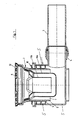
- a drain device comprises receiving means 1, in which a drain unit 2 is introduced from above.
- the receiving means 1 are fluidically connected to a drain pipe 3.
- the receiving means 1 have a Connecting portion 4, which is connected to the drain pipe 3.
- the receiving means 1 a adjoining the connecting portion 4 open-topped pipe socket-like receiving portion 5.
- the receiving means 1 may also be formed as an open end of the drain pipe 3.
- no sleeve of any type whatsoever or no specially shaped connection region for receiving the drainage unit 2 need be formed at this upwardly open or upwardly projecting end of the drainage pipe.
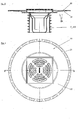
- the drain unit 2 has an upper inlet opening 6 and a lower drain opening 7, which are fluidically connected to each other.
- the drain opening 7 represents the lower end of a pipe stub 8 enclosed by the drain unit 2.
- the pipe stub 8 has on its outer side a lip seal 10 formed from a plurality of lips 9 arranged one above the other.
- the lip seal 10 can either be sprayed on the pipe socket 8 from the outside or be pushed onto the pipe socket 8.
- the lip seal 10 is in particular made in one piece and is preferably made of elastomers.
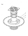
- an odor trap 11 a, 1 1 b is introduced into the pipe socket 8 from above. Furthermore, the drain unit 2 is provided on its upper side with a cover 12.
- a drain unit 13 At the in Fig. 4 shown embodiment of a drain unit 13 are the same parts with the same reference numerals. At this
- Drain unit 13 is received in the pipe socket 8 no odor trap.
- the cover 14 of the drain unit 13 is different than in FIG Fig. 3 provided with a hinged lid 15.
- a drainage unit 2 provided with odor trap 1 1 a, 1 1 b with a hinged lid.
- a drain unit 13 which has no odor trap, with a simple cover without hinged lid.
- a drainage unit may comprise a cleaning closure.
- the drain unit can continue to have a gas-tight manner by means of a screw on the drainage unit fixable cover.
- the drainage device is equipped with a Dünnbettflansch 20.
- the Dünnbettflansch 20 is designed substantially as a circumferential collar which extends approximately perpendicularly from the wall of the upper end of the drain unit 2, 13 and the inlet opening 6 surrounded accordingly.
- the thin bed flange 20 may substantially include a flange 21 and a flow 22.
- the flange is preferably a plastic flange, which consists of the same material as the drain unit 2 (at least partially), in particular even configured in one piece with the drain unit 2.
- the flange 21 and the drain unit 2, 13 may be configured correspondingly in one piece or in two parts.
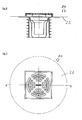
- a second embodiment in which the Dünnbettflansch 20 consists essentially only of a flow 22, in particular of a molded-flow 22.
- the thin-bed flange forms a bonding layer for the tiles or the tile adhesive or other floor covering.
- the Dünnbettflansch is now also the use in sealed floor constructions possible because the Dünnbettflansch 20 can prevent leakage of liquid into the ground in any case.
- the receiving means 1 are formed as an open end of the drain pipe 3.
- the height adjustability of drainage unit 2, 13 with respect to the receiving means 1 is given by the fact that provided with the lip seal 10 pipe socket 8 in the receiving portion 5 or in the drain pipe 3 are moved upwards and / or downwards can.
- the drainage unit 2, 13 comprises an odor trap 11 a, 11 b.
- the drainage unit comprises a cleaning closure.
- the drain unit 2, 13 has a cover 12, 14 on its upper side.
- the cover 14 is provided with a hinged lid 15.
- the cover is gas-tight to the drain unit can be fixed, in particular by means of a screw means.
Landscapes
- Health & Medical Sciences (AREA)
- Life Sciences & Earth Sciences (AREA)
- Engineering & Computer Science (AREA)
- Hydrology & Water Resources (AREA)
- Public Health (AREA)
- Water Supply & Treatment (AREA)
- Sink And Installation For Waste Water (AREA)
Abstract
Description
Die vorliegende Erfindung betrifft eine Ablaufvorrichtung gemäß dem Oberbegriff des Anspruchs 1.The present invention relates to a drainage device according to the preamble of claim 1.
Eine Ablaufvorrichtung der vorgenannten Art ist beispielsweise aus der
Die Ablaufvorrichtung, insbesondere die Aufnahmeeinheit, wird in einen Boden eingesetzt und in der Regel umfließt. In diesem Zusammenhang ist zwischen abgedichteten und nicht-abgedichteten Bodenkonstruktionen zu unterscheiden. Eine Ablaufvorrichtung gemäß dem Stand der Technik ist nur für nicht-abgedichtete Bodenkonstruktionen vorgesehen, d.h. es wird letztendlich in Kauf genommen, dass geringe Mengen Wasser bzw. Feuchtigkeit zwischen der Ablaufvorrichtung und den Fliesen in den Boden eindringen kann. Das eingedrungene Wasser wird zwar letztendlich ebenfalls über die Ablaufvorrichtung abgeführt, jedoch handelt es sich hierbei nicht um eine abgedichtete Bodenkonstruktion. Bei einer abgedichteten Bodenkonstruktion steht im Vordergrund, dass kein Wasser in den Boden eindringen soll.The drainage device, in particular the receiving unit, is inserted into a floor and usually flows around. In this context, a distinction is made between sealed and unsealed floor constructions. A prior art draining device is intended only for non-sealed floor constructions, i. It is ultimately accepted that small amounts of water or moisture between the drainage device and the tiles can penetrate into the soil. Although the penetrated water is ultimately also discharged via the drain device, but this is not a sealed floor construction. With a sealed floor construction, the main point is that no water should penetrate the floor.
Hier setzt die vorliegende Erfindung an und macht es sich zur Aufgabe eine Ablaufvorrichtung vorzuschlagen, die für abgedichtete Bodenkonstruktionen geeignet ist.This is where the present invention is based and makes it its task to propose a drainage device which is suitable for sealed floor constructions.
Erfindungsgemäß wird diese Aufgabe durch eine Ablaufvorrichtung mit den kennzeichnenden Merkmalen des Anspruchs 1 gelöst. Dadurch, dass die Ablaufeinheit mit einem um die Einlauföffnung umlaufenden Dünnbettflansch ausgestattet ist, ist nun auch der Einsatz in abgedichteten Bodenkonstruktionen möglich.According to the invention this object is achieved by a drain device with the characterizing features of claim 1. The fact that the drain unit is equipped with a circulating around the inlet opening Dünnbettflansch, the use in sealed floor constructions is now possible.
Weitere vorteilhafte Ausgestaltungen der vorliegenden Erfindung ergeben sich aus den Merkmalen der rückbezogenen Unteransprüche.Further advantageous embodiments of the present invention will become apparent from the features of the dependent claims.
Insbesondere die Ausgestaltung des Dünnbettflansches lediglich aus einem Fließ stellt eine sehr kostengünstige Alternative zur Bereitstellung eines Dünnbettflansches dar.In particular, the design of the Dünnbettflansches only from a flow is a very cost-effective alternative to provide a Dünnbettflansches.
Weitere Merkmale und Vorteile der vorliegenden Erfindung werden deutlich anhand der nachfolgenden Beschreibung bevorzugter Ausführungsbeispiele unter Bezugnahme auf die beiliegenden Abbildungen. Darin zeigen
- Fig. 1
- eine Schnittansicht einer Ablaufvorrichtung gemäß dem Stand der Technik;
- Fig. 2
- eine teilweise geschnittene Explosionsansicht der von der Ablaufvorrichtung gemäß
Fig. 1 umfassten Abflusseinheit; - Fig. 3
- die Abflusseinheit gemäß
Fig. 2 im zusammengebauten Zustand; - Fig. 4
- eine Schnittansicht einer weiteren Ausführungsform einer Abflusseinheit gemäß dem Stand der Technik;
- Fig. 5
- eine Schnittansicht einer Ablaufeinheit für eine erfindungsgemäße Ablaufvorrichtung;
- Fig. 6
- eine Draufsicht auf eine Ablaufeinheit für eine erfindungsgemäße Ablaufvorrichtung;
- Fig. 7
- eine Explosionsansicht einer Ablaufeinheit für eine erfindungsgemäße Ablaufvorrichtung;
- Fig. 8
- eine Schnittansicht einer Ablaufeinheit für eine erfindungsgemäße Ablaufvorrichtung in einer alternativen Ausgestaltung des Dünnbettflansches (nur Fliess);
- Fig. 1
- a sectional view of a drain device according to the prior art;
- Fig. 2
- a partially sectioned exploded view of the of the drain device according to
Fig. 1 included drainage unit; - Fig. 3
- the drainage unit according to
Fig. 2 in the assembled state; - Fig. 4
- a sectional view of another embodiment of a drain unit according to the prior art;
- Fig. 5
- a sectional view of a drain unit for a drain device according to the invention;
- Fig. 6
- a plan view of a drain unit for a drain device according to the invention;
- Fig. 7
- an exploded view of a drain unit for a drain device according to the invention;
- Fig. 8
- a sectional view of a drain unit for a drain device according to the invention in an alternative embodiment of the Dünnbettflansches (only Fliess);
Folgende Bezugszeichen werden in den Zeichnungen verwendet:
- 1
- Aufnahmemittel
- 2
- Ablaufeinheit
- 3
- Abflussrohr
- 4
- Verbindungsabschnitt
- 5
- Aufnahmeabschnitt
- 6
- Einlauföffnung
- 7
- Ablauföffnung
- 8
- Rohrstutzen
- 9
- Lippen
- 10
- Lippendichtung
- 11 a
- Geruchsverschluss
- 11 b
- Geruchsverschluss
- 12
- Abdeckung
- 13
- Ablaufeinheit
- 14
- Abdeckung
- 15
- Deckel
- 20
- Dünnbettflansch
- 21
- Flansch
- 22
- Fließ
- 1
- receiving means
- 2
- drain assembly
- 3
- waste pipe
- 4
- connecting portion
- 5
- receiving portion
- 6
- inlet opening
- 7
- drain hole
- 8th
- pipe socket
- 9
- lips
- 10
- lip seal
- 11 a
- trap
- 11 b
- trap
- 12
- cover
- 13
- drain assembly
- 14
- cover
- 15
- cover
- 20
- thin bed flange
- 21
- flange
- 22
- flow
Aus
Weiterhin weisen die Aufnahmemittel 1 einen sich an dem Verbindungsabschnitt 4 anschließenden oben offenen rohrstutzenartigen Aufnahmeabschnitt 5 auf. Anstelle einer derartigen Kombination aus einem Verbindungsabschnitt 4 und einem Aufnahmeabschnitt 5 können die Aufnahmemittel 1 auch als nach oben offenes Ende des Abflussrohres 3 ausgebildet sein. Insbesondere braucht an diesem nach oben offenen bzw. nach oben ragenden Ende des Abflussrohres keine wie auch immer geartete Muffe oder kein besonders geformter Anschlussbereich für die Aufnahme der Ablaufeinheit 2 ausgebildet sein.Furthermore, the receiving means 1 a adjoining the connecting portion 4 open-topped pipe socket-like receiving portion 5. Instead of such a combination of a connecting portion 4 and a receiving portion 5, the receiving means 1 may also be formed as an open end of the drain pipe 3. In particular, no sleeve of any type whatsoever or no specially shaped connection region for receiving the
Die Ablaufeinheit 2 weist eine obere Einlauföffnung 6 sowie eine untere Ablauföffnung 7 auf, die strömungstechnisch miteinander verbunden sind. Die Ablauföffnung 7 stellt in dem abgebildeten Ausführungsbeispiel das untere Ende eines von der Ablaufeinheit 2 umfassten Rohrstutzen 8 dar. Der Rohrstutzen 8 weist auf seiner Außenseite eine aus mehreren übereinander angeordneten Lippen 9 gebildete Lippendichtung 10 auf.The
Die Lippendichtung 10 kann entweder auf den Rohrstutzen 8 von außen aufgespritzt sein oder aber auf den Rohrstutzen 8 aufgeschoben sein. Die Lippendichtung 10 ist insbesondere einstückig ausgeführt und besteht vorzugsweise aus Elastomeren.The
In dem in
Bei der in
Ablaufeinheit 13 ist in dem Rohrstutzen 8 kein Geruchsverschluss aufgenommen. Die Abdeckung 14 der Ablaufeinheit 13 ist jedoch anders als in
Eine weitere Ausführungsform einer Ablaufeinheit kann einen Reinigungsverschluss aufweisen. Die Ablaufeinheit kann dabei weiterhin eine vermittels eines Schraubmittels gasdicht an der Ablaufeinheit festlegbare Abdeckung aufweisen.Another embodiment of a drainage unit may comprise a cleaning closure. The drain unit can continue to have a gas-tight manner by means of a screw on the drainage unit fixable cover.
Erfindungsgemäß ist nunmehr vorgesehen, dass die Ablaufvorrichtung mit einem Dünnbettflansch 20 ausgestattet ist. Der Dünnbettflansch 20 ist im Wesentlichen als umlaufender Kragen ausgestaltet, der sich in etwa senkrecht von der Wand des oberen Endes der Ablaufeinheit 2, 13 erstreckt und die Einlauföffnung 6 entsprechend umrandet.According to the invention it is now provided that the drainage device is equipped with a
Es sind im Wesentlichen mindestens zwei verschiedene Ausführungsformen des Dünnbettflansches 20 denkbar. Einerseits kann der Dünnbettflansch 20 im Wesentlichen einen Flansch 21 und ein Fließ 22 umfassen. Bei dem Flansch handelt es sich vorzugsweise um einen Kunststoffflansch, der aus dem gleichen Material wie die Ablaufeinheit 2 besteht (zumindest teilweise), insbesondere sogar einteilig mit der Ablaufeinheit 2 ausgestaltet ist. Der Flansch 21 und die Ablaufeinheit 2, 13 können entsprechend einteilig oder zweiteilig ausgestaltet sein. Denkbar ist ferner eine zweite Ausführungsform, bei welcher der Dünnbettflansch 20 im Wesentlichen nur aus einem Fließ 22, insbesondere aus einem angespritzten Fließ 22 besteht.Essentially, at least two different embodiments of the
In beiden fällen bildet der Dünnbettflansch eine Haftbrücke für die Fliesen bzw. den Fliesenkleber oder sonstigen Bodenbelag. Durch den Dünnbettflansch ist nun auch der Einsatz in abgedichteten Bodenkonstruktionen möglich, da der Dünnbettflansch 20 in jedem Fall ein Durchsickern von Flüssigkeit in den Boden verhindern kann.In both cases, the thin-bed flange forms a bonding layer for the tiles or the tile adhesive or other floor covering. The Dünnbettflansch is now also the use in sealed floor constructions possible because the Dünnbettflansch 20 can prevent leakage of liquid into the ground in any case.
Es kann insbesondere vorteilhafterweise vorgesehen sein, dass die Aufnahmemittel 1 als nach oben offenes Ende des Abflussrohres 3 ausgebildet sind.It may in particular be advantageously provided that the receiving means 1 are formed as an open end of the drain pipe 3.
Ferner kann insbesondere vorteilhafterweise vorgesehen sein, dass die Höhenverstellbarkeit von Ablaufeinheit 2, 13 gegenüber den Aufnahmemitteln 1 dadurch gegeben ist, dass der mit der Lippendichtung 10 versehene Rohrstutzen 8 in dem Aufnahmeabschnitt 5 oder in dem Abflussrohr 3 nach oben und/oder nach unten bewegt werden kann.Furthermore, it may be advantageously provided in particular that the height adjustability of
Ferner kann insbesondere vorteilhafterweise vorgesehen sein, dass die Ablaufeinheit 2, 13 einen Geruchsverschluss 11 a, 1 1 b umfasst.Furthermore, it may be advantageously provided, in particular, that the
Ferner kann insbesondere vorteilhafterweise vorgesehen sein, dass die Ablaufeinheit einen Reinigungsverschluss umfasst.Furthermore, it can be advantageously provided in particular that the drainage unit comprises a cleaning closure.
Ferner kann insbesondere vorteilhafterweise vorgesehen sein, dass die Ablaufeinheit 2, 13 auf ihrer Oberseite eine Abdeckung 12, 14 aufweist.Furthermore, it may be advantageously provided, in particular, that the
Ferner kann insbesondere vorteilhafterweise vorgesehen sein, dass die Abdeckung 14 mit einem klappbaren Deckel 15 versehen ist.Furthermore, it can be advantageously provided in particular that the
Ferner kann insbesondere vorteilhafterweise vorgesehen sein, dass die Abdeckung gasdicht an der Ablaufeinheit festlegbar ist, insbesondere vermittels eines Schraubmittels.Furthermore, it may be advantageously provided in particular that the cover is gas-tight to the drain unit can be fixed, in particular by means of a screw means.
Claims (15)
einsteckbar ist,
die Ablaufeinheit (2, 13) mit einem um die Einlauföffnung (6) umlaufenden Dünnbettflansch (20) ausgestattet ist.Drainage device for floor mounting, comprising
is pluggable,
the drain unit (2, 13) is equipped with a thin-bed flange (20) revolving around the inlet opening (6).
Applications Claiming Priority (1)
| Application Number | Priority Date | Filing Date | Title |
|---|---|---|---|
| DE200920015791 DE202009015791U1 (en) | 2009-11-18 | 2009-11-18 | draining device |
Publications (1)
| Publication Number | Publication Date |
|---|---|
| EP2333172A1 true EP2333172A1 (en) | 2011-06-15 |
Family
ID=41694280
Family Applications (1)
| Application Number | Title | Priority Date | Filing Date |
|---|---|---|---|
| EP10191780A Withdrawn EP2333172A1 (en) | 2009-11-18 | 2010-11-18 | Drainage device |
Country Status (2)
| Country | Link |
|---|---|
| EP (1) | EP2333172A1 (en) |
| DE (1) | DE202009015791U1 (en) |
Cited By (2)
| Publication number | Priority date | Publication date | Assignee | Title |
|---|---|---|---|---|
| CN109267639A (en) * | 2018-11-13 | 2019-01-25 | 武汉冶建筑安装工程有限责任公司 | Floor drain leakage preventing structure and its construction method |
| EP3495576A3 (en) * | 2017-02-07 | 2019-07-03 | Wiedemann GmbH | System consisting of an odour trap and a receiving body and an odour trap |
Families Citing this family (8)
| Publication number | Priority date | Publication date | Assignee | Title |
|---|---|---|---|---|
| NL2005289C2 (en) * | 2010-08-30 | 2012-03-01 | Easy Sanitairy Solutions Bv | SHOWER FLOOR SEALING SYSTEM. |
| DE102010037342B4 (en) * | 2010-09-06 | 2015-04-02 | Aco Severin Ahlmann Gmbh & Co. Kg | Drainage device and method for installing a drainage device |
| CN101949168B (en) * | 2010-09-17 | 2012-03-28 | 徐彬 | Deep-seepage deodorizing floor drain |
| DK2818602T3 (en) * | 2013-06-26 | 2017-09-11 | Geberit Int Ag | Outlet Interior |
| CN104452904B (en) * | 2013-09-17 | 2016-11-23 | 博麟水电材料有限公司 | Downpipe line structure |
| DE102014119584B3 (en) * | 2014-12-23 | 2016-05-19 | Wedi Gmbh | Sealing insert for a water outlet |
| DE102014119582B4 (en) * | 2014-12-23 | 2016-10-27 | Wedi Gmbh | Sealing insert for a water outlet |
| DE202021101812U1 (en) | 2021-04-06 | 2022-07-22 | Dallmer Gmbh & Co. Kg | Device for a drainage device arranged in the floor of a room and drainage device with such a device |
Citations (4)
| Publication number | Priority date | Publication date | Assignee | Title |
|---|---|---|---|---|
| DE29505860U1 (en) * | 1995-04-05 | 1996-05-09 | SITA-Bauelemente GmbH, 33442 Herzebrock-Clarholz | Device for sealing a water inlet |
| EP1329562A2 (en) * | 2002-01-16 | 2003-07-23 | Dallmer GmbH & Co. KG | Floor drain |
| DE102005036576A1 (en) * | 2004-12-23 | 2006-07-20 | Dallmer Gmbh & Co.Kg | Drainage installation for fixing on ground plate with opening for waste water, arrangement of same on ground plate has pipe parts movable relative to each other thereby covering opening in ground plate and inflow pipe |
| DE102007062569A1 (en) * | 2007-12-22 | 2008-07-03 | Dallmer Gmbh & Co. Kg | Guttering production method for producing a guttering drain-off body for the field of sanitation produces guttering made through dishing/swaging |
-
2009
- 2009-11-18 DE DE200920015791 patent/DE202009015791U1/en not_active Expired - Lifetime
-
2010
- 2010-11-18 EP EP10191780A patent/EP2333172A1/en not_active Withdrawn
Patent Citations (5)
| Publication number | Priority date | Publication date | Assignee | Title |
|---|---|---|---|---|
| DE29505860U1 (en) * | 1995-04-05 | 1996-05-09 | SITA-Bauelemente GmbH, 33442 Herzebrock-Clarholz | Device for sealing a water inlet |
| EP1329562A2 (en) * | 2002-01-16 | 2003-07-23 | Dallmer GmbH & Co. KG | Floor drain |
| DE10201345A1 (en) | 2002-01-16 | 2003-07-24 | Dallmer Gmbh & Co Kg | Drain device for installation in the floor of a room |
| DE102005036576A1 (en) * | 2004-12-23 | 2006-07-20 | Dallmer Gmbh & Co.Kg | Drainage installation for fixing on ground plate with opening for waste water, arrangement of same on ground plate has pipe parts movable relative to each other thereby covering opening in ground plate and inflow pipe |
| DE102007062569A1 (en) * | 2007-12-22 | 2008-07-03 | Dallmer Gmbh & Co. Kg | Guttering production method for producing a guttering drain-off body for the field of sanitation produces guttering made through dishing/swaging |
Cited By (2)
| Publication number | Priority date | Publication date | Assignee | Title |
|---|---|---|---|---|
| EP3495576A3 (en) * | 2017-02-07 | 2019-07-03 | Wiedemann GmbH | System consisting of an odour trap and a receiving body and an odour trap |
| CN109267639A (en) * | 2018-11-13 | 2019-01-25 | 武汉冶建筑安装工程有限责任公司 | Floor drain leakage preventing structure and its construction method |
Also Published As
| Publication number | Publication date |
|---|---|
| DE202009015791U1 (en) | 2010-02-18 |
Similar Documents
| Publication | Publication Date | Title |
|---|---|---|
| EP2333172A1 (en) | Drainage device | |
| EP2286850B1 (en) | Supply unit for dialysis machines | |
| DE102006032017B3 (en) | shower head | |
| EP2586919A2 (en) | Sanitary fitting | |
| AT516982B1 (en) | Device for finishing a floor section having a slab or stone covering | |
| EP1329562B1 (en) | Floor drain | |
| EP3064667B1 (en) | Sealant for the sealing of a draining device | |
| EP2453065A2 (en) | Drainage fitting with concealedly positionable overflow | |
| DE202014007357U1 (en) | Floor drain with sealing mat | |
| DE102012102929B4 (en) | Sanitary arrangement | |
| EP2711475B1 (en) | Sink with vented draining device | |
| EP1561868B1 (en) | Drainage device for shower tray | |
| EP3428354B1 (en) | Drain gutter arrangement | |
| DE10360310A1 (en) | draining device | |
| DE102008059514A1 (en) | Drainage device for damp location, particularly for shower, comprises channel shaped drainage body with intake opening for sewage water, where drainage body comprises discharge opening for sewage water | |
| DE102007044422B4 (en) | Wasserablauftülle | |
| EP3074576A1 (en) | Drain device and inner pipe element for at least partial insertion into a drain insert of a drain device | |
| DE4038418C2 (en) | Flush-mounted box for a sanitary fitting | |
| DE10204683B4 (en) | pool | |
| DE202007007371U1 (en) | Variable shower area | |
| EP1762289A2 (en) | Sedimentation device | |
| DE102006038664B4 (en) | manhole base | |
| EP2808458B1 (en) | Water drainage device for a shower and shower floor element | |
| WO2017144542A1 (en) | Connection device between a gutter and gully | |
| EP3770348B1 (en) | Mounting block |
Legal Events
| Date | Code | Title | Description |
|---|---|---|---|
| PUAI | Public reference made under article 153(3) epc to a published international application that has entered the european phase |
Free format text: ORIGINAL CODE: 0009012 |
|
| AK | Designated contracting states |
Kind code of ref document: A1 Designated state(s): AL AT BE BG CH CY CZ DE DK EE ES FI FR GB GR HR HU IE IS IT LI LT LU LV MC MK MT NL NO PL PT RO RS SE SI SK SM TR |
|
| AX | Request for extension of the european patent |
Extension state: BA ME |
|
| 17P | Request for examination filed |
Effective date: 20111215 |
|
| D17P | Request for examination filed (deleted) | ||
| STAA | Information on the status of an ep patent application or granted ep patent |
Free format text: STATUS: THE APPLICATION IS DEEMED TO BE WITHDRAWN |
|
| 18D | Application deemed to be withdrawn |
Effective date: 20111216 |