EP2332682A1 - Method for controlling a hydraulic add-on device and hydraulic add-on device, in particular for breaking, crushing or recycling - Google Patents
Method for controlling a hydraulic add-on device and hydraulic add-on device, in particular for breaking, crushing or recycling Download PDFInfo
- Publication number
- EP2332682A1 EP2332682A1 EP10014855A EP10014855A EP2332682A1 EP 2332682 A1 EP2332682 A1 EP 2332682A1 EP 10014855 A EP10014855 A EP 10014855A EP 10014855 A EP10014855 A EP 10014855A EP 2332682 A1 EP2332682 A1 EP 2332682A1
- Authority
- EP
- European Patent Office
- Prior art keywords
- lifting cylinder
- jaw
- pivotable jaw
- pivotable
- closing movement
- Prior art date
- Legal status (The legal status is an assumption and is not a legal conclusion. Google has not performed a legal analysis and makes no representation as to the accuracy of the status listed.)
- Granted
Links
- 238000000034 method Methods 0.000 title claims abstract description 14
- 238000004064 recycling Methods 0.000 title claims abstract description 8
- 238000005520 cutting process Methods 0.000 claims description 62
- 230000000977 initiatory effect Effects 0.000 claims description 5
- 238000010008 shearing Methods 0.000 claims description 5
- 238000013016 damping Methods 0.000 claims description 3
- 238000007599 discharging Methods 0.000 abstract 1
- 238000000418 atomic force spectrum Methods 0.000 description 5
- XEEYBQQBJWHFJM-UHFFFAOYSA-N Iron Chemical compound [Fe] XEEYBQQBJWHFJM-UHFFFAOYSA-N 0.000 description 4
- 239000012530 fluid Substances 0.000 description 4
- 238000009826 distribution Methods 0.000 description 3
- 238000010586 diagram Methods 0.000 description 2
- 238000009434 installation Methods 0.000 description 2
- 229910052742 iron Inorganic materials 0.000 description 2
- 239000000463 material Substances 0.000 description 2
- 239000002184 metal Substances 0.000 description 2
- 229910052751 metal Inorganic materials 0.000 description 2
- CWYNVVGOOAEACU-UHFFFAOYSA-N Fe2+ Chemical compound [Fe+2] CWYNVVGOOAEACU-UHFFFAOYSA-N 0.000 description 1
- 230000004913 activation Effects 0.000 description 1
- 238000010276 construction Methods 0.000 description 1
- 230000007423 decrease Effects 0.000 description 1
- 238000011161 development Methods 0.000 description 1
- 230000018109 developmental process Effects 0.000 description 1
- ZINJLDJMHCUBIP-UHFFFAOYSA-N ethametsulfuron-methyl Chemical compound CCOC1=NC(NC)=NC(NC(=O)NS(=O)(=O)C=2C(=CC=CC=2)C(=O)OC)=N1 ZINJLDJMHCUBIP-UHFFFAOYSA-N 0.000 description 1
- 230000002349 favourable effect Effects 0.000 description 1
- -1 ferrous metals Chemical class 0.000 description 1
- 238000004904 shortening Methods 0.000 description 1
- 238000003860 storage Methods 0.000 description 1
- 239000013598 vector Substances 0.000 description 1
Images


Classifications
-
- B—PERFORMING OPERATIONS; TRANSPORTING
- B23—MACHINE TOOLS; METAL-WORKING NOT OTHERWISE PROVIDED FOR
- B23D—PLANING; SLOTTING; SHEARING; BROACHING; SAWING; FILING; SCRAPING; LIKE OPERATIONS FOR WORKING METAL BY REMOVING MATERIAL, NOT OTHERWISE PROVIDED FOR
- B23D31/00—Shearing machines or shearing devices covered by none or more than one of the groups B23D15/00 - B23D29/00; Combinations of shearing machines
- B23D31/008—Cutting-up scrap
-
- B—PERFORMING OPERATIONS; TRANSPORTING
- B23—MACHINE TOOLS; METAL-WORKING NOT OTHERWISE PROVIDED FOR
- B23D—PLANING; SLOTTING; SHEARING; BROACHING; SAWING; FILING; SCRAPING; LIKE OPERATIONS FOR WORKING METAL BY REMOVING MATERIAL, NOT OTHERWISE PROVIDED FOR
- B23D17/00—Shearing machines or shearing devices cutting by blades pivoted on a single axis
- B23D17/02—Shearing machines or shearing devices cutting by blades pivoted on a single axis characterised by drives or gearings therefor
- B23D17/06—Shearing machines or shearing devices cutting by blades pivoted on a single axis characterised by drives or gearings therefor actuated by fluid or gas pressure
-
- E—FIXED CONSTRUCTIONS
- E02—HYDRAULIC ENGINEERING; FOUNDATIONS; SOIL SHIFTING
- E02F—DREDGING; SOIL-SHIFTING
- E02F3/00—Dredgers; Soil-shifting machines
- E02F3/04—Dredgers; Soil-shifting machines mechanically-driven
- E02F3/96—Dredgers; Soil-shifting machines mechanically-driven with arrangements for alternate or simultaneous use of different digging elements
- E02F3/965—Dredgers; Soil-shifting machines mechanically-driven with arrangements for alternate or simultaneous use of different digging elements of metal-cutting or concrete-crushing implements
-
- E—FIXED CONSTRUCTIONS
- E04—BUILDING
- E04G—SCAFFOLDING; FORMS; SHUTTERING; BUILDING IMPLEMENTS OR AIDS, OR THEIR USE; HANDLING BUILDING MATERIALS ON THE SITE; REPAIRING, BREAKING-UP OR OTHER WORK ON EXISTING BUILDINGS
- E04G23/00—Working measures on existing buildings
- E04G23/08—Wrecking of buildings
- E04G23/082—Wrecking of buildings using shears, breakers, jaws and the like
Definitions
- the invention relates to a method for controlling an opening and closing movement of a hydraulic attachment for shearing or crushing structures and a hydraulic attachment, in particular for demolition, for crushing or recycling.
- a generic hitch which is on a boom and a hydraulic system of a carrier device, such as a skid steer loader or excavator connected.
- a connection interface is provided on a housing of the mounting device, on the one hand, the housing of the attachment to the boom, in particular interchangeable, too fix and on the other hand to connect the hydraulic system of the carrier device with hydraulic pressure lines or with an inlet and a drain of the hitch.
- a fixed lower jaw or a fixed lower jaw and a pivotally arranged upper jaw or a pivoting upper jaw is provided, wherein the upper jaw is pivotally mounted about a housing arranged on the bearing axis.
- This pivotable jaw is driven by a single lifting cylinder, so that the jaw can be transferred from an open position by a closing movement in a cutting position and on into a closed position and then by an opening movement back into an open position.
- the lifting cylinder in particular its piston rod, engages the pivotable jaw.
- the lifting cylinder is pivotally mounted on the housing, but stationary, stored.
- Such hydraulic attachments are used to process structures such as scrap. Both iron and non-ferrous metal can be crushed. Such scrap can be in many different forms. For example, these may be ships, rigs or the like. Likewise, it may also be individual metallic components, such as supports, channels, tubes or the like. Furthermore, such attachments can be used for processing structures such as buildings, highways or the like, while a road surface, especially concrete, or other structural parts made of concrete are crushed.
- the arrangement of the lifting cylinder and the design of the pivoting jaw and their storage on the housing is such that with increasing closing movement of the pivoting jaw an increasing pressure force can be built, the pressure force is strongest, as soon as a tip of the movable jaw at the same level or slightly positioned opposite a tip of an opposing jaw.
- this is designed as a pair of scissors, so that an upper and a lower jaw are each driven to pivot about a common bearing axis on the housing.
- the jaws are formed with cutting knives, crushing or crushing teeth or a combination of crushing teeth and cutting blades.
- the invention is therefore based on the object to propose a method for controlling a hydraulic hitch and a hydraulic hitch for shearing or crushing structures, in particular for demolition, comminution or recycling, so that at the beginning of a closing movement of at least one pivoting jaw Increased cutting force is achieved and, moreover, shortened cycle times during opening and closing Closing movement of the at least one pivotable jaw in an opening and cutting and / or closing position are made possible.
- This object is achieved by a method for controlling a hydraulic hitch with an upper and a lower jaw, of which at least one jaw is pivotally mounted on a bearing axis on the housing, solved in which the pivotable jaw by a first and at least one further attacking it Lifting cylinder is driven from an opening into a cutting and / or a closed position and movable back and attack the first and at least one further lifting cylinder with a divergent lever arm to Krafteitechnisch on the pivoting jaw.
- the lifting cylinders acting on the jaw are simultaneously subjected to pressure.
- an increased pressure force is generated already at the beginning of a closing movement, so that the sum of the generated compressive forces by the attacking on the pivoting jaw lifting cylinder already at the beginning of the closing movement is significantly higher than is the case with the aforementioned prior art, in which the Construction device has only a single lifting cylinder.
- An alternative embodiment according to the invention for controlling the at least one pivotable jaw provides that initially only one lifting cylinder is pressurized to initiate a closing movement of the at least one pivoting jaw from an opening position and pressure is also applied to the at least one further lifting cylinder.
- only one of the lifting cylinders is acted upon in order to achieve a fast closing speed and as soon as the application of an increased pressure force is required, which is switched on at least one further lifting cylinder at a low labor force, which only takes place a closing movement without cutting and Zemalmarbeit.
- a demand-oriented cutting force increase can be achieved in a preceding closing movement in rapid traverse.
- the lifting cylinder or cylinders acting on the at least one pivotable jaw are actuated for an opening and / or closing movement via at least one valve of a hydraulic control device.
- a valve of a hydraulic control device By such a valve, a faster travel speed of the pivoting jaw can be achieved.
- a flexible and fast switching on and off of the individual lifting cylinders are made possible.
- a further preferred embodiment of the method provides that for a closing movement of the at least one pivotable jaw initially only that lifting cylinder is driven, which has a higher closing speed and / or a larger lever arm than the at least one further lifting cylinder in a first closing phase and in another Closing movement, in which a pressure force increase takes place, which is switched on and controlled at least one further lifting cylinder, so that at this time the closing movement, an increased cutting force is generated.
- This arrangement has the advantage that until the actual application of the required cutting force, a rapid feeding or closing movement can take place and at the time when the increased cutting force is required, such is generated.
- a further preferred embodiment of the method provides that the at least one further lifting cylinder is controlled during a closing movement of the pivotable jaw as a damping cylinder, which counteracts the at least one, the closing movement performing lifting cylinder.
- a sudden occurs Rupture which causes a rapid relief of at least one controlled lifting cylinder.
- This can cause seals in the lift cylinder, such as piston seals and piston rod seals, to be damaged.
- at least one further lifting cylinder is operated as a damping cylinder, which is driven with opposite pressure force to the cutting movement performing lifting cylinder to dampen this sudden discharge and counteract this. This has the advantage that with such sudden reliefs resulting damage to the seal of the lifting cylinder can be avoided.
- the problem underlying the invention is achieved by a hydraulic attachment for shearing or crushing structures, in particular for demolition, for comminution or for recycling, in which at least one pivotable jaw, which is pivotally mounted about a mounted on a housing bearing axis , a first lifting cylinder and a further lifting cylinder acts thereon, wherein the at least two attacking on the pivotable jaw lifting cylinder engage with a divergent lever arm on the pivoting jaw.
- This can be achieved in particular during a cutting movement or closing movement of the hitch an increase in force, so that, for example.
- the at least one additional lifting cylinder can muster the required cutting or closing force because of Lever arm in this area is larger or maximum.
- a further preferred embodiment of the invention provides that the respective points of attack of the lifting cylinder on the pivotable jaw differ from each other at a distance from the bearing axis of the pivotable jaw.
- This refinement furthermore has the advantage that, by using at least two lifting cylinders, a force distribution takes place when the force is introduced into the pivotable jaw.
- a force distribution takes place when the force is introduced into the pivotable jaw.
- each of the pivotable jaw opposite points of attack of the lifting cylinder are in turn arranged on a pivoting jaw or on a housing. It can alternatively be provided that these attack points are separated or at a common point of attack. This also allows in a simple manner the positioning of the at least one further lifting cylinder to the first lifting cylinder while maintaining the pivoting movement of the pivoting jaw. In addition, targeted different degrees of closing forces can be achieved over the course of a closing movement of the pivoting jaw, so that the cutting force curve over the cutting area can be designed accordingly.
- the pivotable jaw acts on the pivotable jaw at least one further lifting cylinder whose longitudinal axis is arranged in a deviating from the longitudinal axis of the first lifting cylinder angle of attack.
- This arrangement has the advantage that the at least two lift cylinders acting on the pivotable jaw have different lever arms due to their different angles of attack and thus produce different initial cutting forces, wherein it is provided in particular that an increased cutting force is generated already at the beginning of a closing movement from an opening position.
- An alternative preferred embodiment of the invention provides that the point of application of the at least one further lifting cylinder in the Point of attack of the first lifting cylinder is located. As a result, usually the angle of attack of the lifting cylinder can be increased to each other and a central force on the jaw can be achieved. According to an alternative embodiment of the invention, it is provided that the longitudinal axis of the first lifting cylinder and the longitudinal axis of the at least one further lifting cylinder, both of which act on the pivotable jaw at different points of attack, are aligned parallel to each other. These alternative orientation of the lifting cylinder with the distance from the bearing axis divergent attack points on the pivoting jaw, allow analogous advantages such as the arrangement of the lifting cylinder with respect to their longitudinal axis in mutually different angles of attack.
- a cutting force increase is generated.
- the arrangement of at least two lifting cylinders, which engage with different angles of attack on the pivoting jaw, a cutting force increase at the beginning of a closing movement of the pivoting jaw is achieved by up to 50%, for example.
- a further preferred embodiment of the invention provides that the first and at least one further lifting cylinder are supported or counter-supported on the housing.
- This can be given a simple structural design.
- the use of smaller lifting cylinders has the advantage that they have a larger stroke with the same installation length, as they have a smaller dead size. The dead size of a lifting cylinder is determined by the difference between the total length of the lifting cylinder and its stroke length.
- the use of smaller lifting cylinders has the advantage that a higher operating speed is possible and that in addition there is a smaller inertia.
- the first and at least one further lifting cylinder engage with the respective piston rods on the pivotable jaw.
- the housing of the lifting cylinder is arranged on the pivotable jaw.
- the lifting cylinder can also be oriented in opposite directions.
- the first lifting cylinder at an opening position of the pivotable jaw on a larger lever arm than the at least one further lifting cylinder.
- the first lifting cylinder can be arranged in a more favorable lever arm ratio than is the case with the use of only a single lifting cylinder.
- an increased cutting force is achieved, in particular at the beginning of the cutting movement, at least at the beginning of the closing movement of the at least one jaw.
- a further preferred embodiment of the invention provides that the lifting cylinder acting on the pivotable jaw can be acted upon in parallel with pressure.
- a hydraulic control device is used, from which a piston-side and a piston rod-side connecting line are guided to the respective lifting cylinder.
- the sum of the cylinder volumes of the lifting cylinders, which act on the pivotable jaw is less than or equal to the hydraulic delivery volume of the hydraulic system.
- the lift cylinders acting on the pivotable jaw have different piston diameters. This allows a high degree of flexibility in the design of the cutting force curve and to control the opening and closing movement of the at least one jaw can be achieved.
- the hydraulic hitch 11 comprises a housing 12 with a connection interface 14, via which this hydraulic hitch 11 on a boom, not shown, and a hydraulic system of a carrier, not shown, for example, a skid steer loader or excavator, connectable and easily replaceable.
- the housing 12 comprises a fixed lower jaw 16 or a fixed lower jaw and a pivotable upper jaw 18 or a pivotable upper jaw.
- the upper jaw 18 is pivotable about a bearing axis 19, wherein the bearing axis 19 is fixedly provided on the housing 12.
- the lower jaw 16 may also be pivotable about the bearing axis 19 in analogy to the upper jaw 18.
- the upper and lower jaws 18, 16 are equipped with a cutting tool 20.
- a cutting tool 20 By such a mounting device 11, in particular the cutting of iron and non-ferrous metals allows and thus be used for recycling.
- the upper and lower jaw can also be provided exclusively with Zermalmzähnen or additionally with Zermalmzähen.
- a hydraulic lifting cylinder 26 is pressurized, said hydraulic lifting cylinder 26 is controlled by a hydraulic control device 28.
- This control device 28 is supplied with an inlet 29 from the hydraulic system.
- the hydraulic fluid is via a Run 30 returned from the control device 28 in the hydraulic system.
- the hydraulic lifting cylinder 26 is pressurized, so that a piston rod 32 is extended along a longitudinal axis 33 of the lifting cylinder 26. Due to the pivotable arrangement of the upper jaw 18 about the bearing axis 19 results in a lever arm 31, which is substantially smaller at the beginning of the cutting phase than the lever arm 31 in FIG. 1b in which the upper jaw 18 has been transferred to a cutting position 22.
- the lever arm 31 is largest in this cutting position, so that the compressive force acting in the longitudinal axis 33 produces maximum leverage.
- FIGS. 1a and b The structural design of the hydraulic hitch 11 according to the FIGS. 1a and b is in the embodiment of the invention, the hitch 11 in the FIGS. 2a to c maintained in principle.
- the in the FIGS. 2a to c illustrated embodiment of the hitch 11 has as in the FIGS. 1a and 1b a mouth opening 37, which cutting tips 38 and shear strips 39 include.
- This hitch 11 is designed as scrap shears for scrapping.
- a combination of Schneidmaschinemaschinemaschine or at the mouth opening 37 may be provided only a Zermalmwerkmaschine.
- the Zermalmwerkmaschine includes, for example, Zermalmzähne.
- FIGS. 2a to c is different from the embodiment according to FIGS. 1a and 1b provided that the upper jaw 18 is actuated by a first lifting cylinder 26 and by at least one further lifting cylinder 41.
- the lifting cylinder 41 engages, for example, with its piston rod 42 at an adjacent point 43 to the point 45 on the jaw 18 at which the piston rod 32 of the lifting cylinder 26 is arranged. This results in a deviating from the lever arm 34 of the first lifting cylinder 26 lever arm 48 for the lifting cylinder 41 relative to the bearing axis 19.
- a longitudinal axis 47 of the lifting cylinder 41 in a different angle of attack 49 to the longitudinal axis 33 of Lifting cylinder 26 is arranged.
- the angle of attack of the lifting cylinders 26, 41 to the jaw 18 is determined by the orientation of the longitudinal axis 47 of the lifting cylinder 41 and a point 44 of the lifting cylinder 41 on the housing 12 on the one hand and the point of application 43 on the pivoting jaw 18 and upper jaw 18 on the other.
- the length of the effective lever arm 48 is determined by the angle of attack 49 of the lifting cylinder 26, 41 and the distance of the points 43, 45 to the bearing axis 19. This allows a simple design and determination of an initial cutting force and a cutting force curve over the entire closing movement.
- each of the two lifting cylinders 26, 41 can be made smaller than the single-stroke cylinders used in the prior art. This has the advantage that a larger selection of lifting cylinders is available. In addition, this arrangement has the advantage that a better force distribution when initiating the cutting force in the upper jaw 18 due to the separate points of attack 43 and 45 on the one hand and the separate support points of the lifting cylinder 26, 41 is given to the housing 12.
- the upper jaw 18 is transferred to a cutting position 22, as in FIG. 2b is shown.
- This cutting position 22 is reached when the cutting tips 28 are opposite each other or a cutting tip 28 of the upper jaw 18 dips into the cutting tip 28 of the lower jaw 16.
- Figure 2c has the upper jaw 18, the closed position 23 occupied.
- a parallel alignment of the longitudinal axis 33, 47 may be provided instead of aligning the longitudinal axis 33, 47 of the first lifting cylinder 26 and the at least one further lifting cylinder 41 at a different angle. This allows the analogous advantages to be achieved. In some cases, such an arrangement may also be suitable due to the given installation space.
- the illustrated hitch 11 in the FIGS. 2a to 2c can also attack a third lifting cylinder or other lifting cylinder on the upper jaw 18.
- This may mean, on the one hand, that the longitudinal axes of the lifting cylinders 26, 41 acting on the pivotable jaw 16, 18 all differ from one another.
- the lifting cylinders 26, 41 are all aligned parallel to each other or that a combination of the two embodiments is possible, that is, both parallel to each other as well as in a different Angled lifting cylinder 26, 41 can attack on a pivoting jaw.
- the pressure force acting on the pivotable jaw 18 increases.
- both a closed housing, as in the FIGS. 2a to 2c is shown, as well as an open housing, which may be formed, for example in the form of a support frame or a support frame.
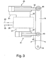
- FIG. 3 schematically is a hydraulic diagram of the control device 28 for controlling the two lifting cylinders 26, 41 of the hitch 11 according to the FIGS. 2 a to c shown.
- the control device 28 Via the inlet 29, the control device 28 is supplied with hydraulic fluid for initiating a pivoting movement.
- From the control device 28 leads to each lifting cylinder 26, 41 a piston-side connecting line 51.
- a piston rod-side connecting line 52 is arranged between the lifting cylinder 26, 41 and the control device 28.
- the attacking on the pivoting jaw 18 lifting cylinders 26, 41 are connected in parallel.
- the pivotable jaw 18, which is driven pivotably about the bearing axis 19, is in FIG. 3 only symbolically represented.
- the control device 28 includes at least one valve not shown in detail.
- other valves for controlling the lifting cylinder 26, 41 may be provided individually or jointly, which can be selectively controlled.
- the control device 28 a flexible control of the lifting cylinder 26, 41 is possible.
- the at least two lifting cylinders 26, 41 are pressurized simultaneously. Due to the fact that the lifting cylinders 26, 41 are connected in parallel, they do not interfere.
- a valve for rapid traverse can be switched on until a pressure force increase takes place or the cutting process begins. Subsequently, the valve is closed to further control the cutting process.
- the opening movement of the pivotable jaw 18 in an open position 21 for example, only one of the two lifting cylinders 26, 41 are pressurized.
- a quick valve for both an opening movement of the cylinder as well as for at least a first phase of a closing movement are switched on to achieve short cycle times. In this case, for example, the hydraulic fluid is supplied from a rod-side chamber into a piston-side chamber or vice versa. When a certain pressure is reached, the rapid traverse valve is closed.
- a closing movement that first the hydraulic cylinder 26 or the hydraulic cylinder 41 with pressure, in particular via at least one valve, is applied until a cutting force increase is felt, so that then the other lifting cylinder 26, 41 via a valve will apply to apply the increased cutting force.
- the opening movement is preferably only with a lifting cylinder 26 or 41, in particular via one or more valves, driven to allow a quick opening time or return of the upper jaw 18 in an open position 21.
Abstract
Description
Die Erfindung betrifft ein Verfahren zur Ansteuerung einer Öffnungs- und einer Schließbewegung einer hydraulischen Anbauvorrichtung zum Scheren oder Zermalmen von Strukturen sowie eine hydraulische Anbauvorrichtung, insbesondere für den Abbruch, für die Zerkleinerung oder das Recycling.The invention relates to a method for controlling an opening and closing movement of a hydraulic attachment for shearing or crushing structures and a hydraulic attachment, in particular for demolition, for crushing or recycling.
Aus der
Solche hydraulische Anbauvorrichtungen werden dafür verwendet, um Strukturen, wie beispielsweise Schrott, zu verarbeiten. Dabei kann sowohl Eisen als auch Nichteisenmetall zerkleinert werden. Derartiger Schrott kann in vielen verschiedenen Formen vorliegen. Beispielsweise können dies Schiffe, Bohrinseln oder dergleichen sein. Ebenso können es auch einzelne metallische Bestandteile sein, wie beispielsweise Träger, Kanäle, Röhren oder dergleichen. Des Weiteren können solche Anbauvorrichtungen zur Bearbeitung von Strukturen wie beispielsweise Gebäude, Autobahnen oder dergleichen eingesetzt werden, wobei dabei ein Straßenbelag, insbesondere aus Beton, oder sonstige Bauwerksteile aus Beton zermalmt werden.Such hydraulic attachments are used to process structures such as scrap. Both iron and non-ferrous metal can be crushed. Such scrap can be in many different forms. For example, these may be ships, rigs or the like. Likewise, it may also be individual metallic components, such as supports, channels, tubes or the like. Furthermore, such attachments can be used for processing structures such as buildings, highways or the like, while a road surface, especially concrete, or other structural parts made of concrete are crushed.
Die Anordnung des Hubzylinders sowie die Ausgestaltung der schwenkbaren Backe und deren Lagerung am Gehäuse erfolgt derart, dass mit zunehmender Schließbewegung der schwenkbaren Backe eine zunehmende Druckkraft aufgebaut werden kann, wobei die Druckkraft am stärksten ist, sobald eine Spitze der bewegbaren Backe auf gleicher Höhe oder geringfügig gegenüber einer Spitze einer gegenüberliegenden Backe positioniert ist.The arrangement of the lifting cylinder and the design of the pivoting jaw and their storage on the housing is such that with increasing closing movement of the pivoting jaw an increasing pressure force can be built, the pressure force is strongest, as soon as a tip of the movable jaw at the same level or slightly positioned opposite a tip of an opposing jaw.
Alternativ zu dieser Ausführungsform der hydraulischen Anbauvorrichtung ist des Weiteren bekannt, dass diese als Schere ausgebildet ist, so dass eine obere und eine untere Backe jeweils schwenkbeweglich um eine gemeinsame Lagerachse am Gehäuse angetrieben werden.As an alternative to this embodiment of the hydraulic attachment, it is further known that this is designed as a pair of scissors, so that an upper and a lower jaw are each driven to pivot about a common bearing axis on the housing.
In Abhängigkeit des Einsatzzweckes werden die Backen mit Schneidmessern, mit Brech- oder Zermalmzähnen oder einer Kombination aus Zermalmzähnen und Schneidmessern ausgebildet.Depending on the intended use, the jaws are formed with cutting knives, crushing or crushing teeth or a combination of crushing teeth and cutting blades.
Die Anforderungen an solche hydraulischen Anbaugeräte steigen stetig an. Insbesondere sollen bei gleichbleibenden Baugrößen erhöhte Druckkräfte, insbesondere Schneid- und/oder Zermalmkräfte, erzeugt werden können. Dies beruht zum einen darauf, dass für diese hydraulischen Anbaugeräte, welche selbst in einer kleinen Ausführungsform ein Gewicht von wenigstens 200 kg aufweisen, die bisherige Baugröße erhalten bleibt, um eine schnelle Handhabung zu ermöglichen. Darüber hinaus sollen größere Strukturen und dickere Wandstärken bei gleicher Baugröße zerkleinert, abgeschert oder zermalmt werden. Insbesondere bei der Zerkleinerung von Rohren tritt das Problem auf, dass diese bei einer maximalen Öffnungsposition gerade von einer Maulöffnung umgriffen werden können, jedoch die anfängliche Schneidkraft zu gering ist, so dass solche Rohre oftmals nicht geschnitten werden können und eine größere Anbauvorrichtung erforderlich ist. Darüber hinaus weisen solche Anbauvorrichtungen den Nachteil auf, dass eine sehr niedrige Öffnungs-und Schließgeschwindigkeit der schwenkbaren Backe gegeben ist, welche durch das hohe Rücklaufvolumen zwischen Druckkolbenfläche und Kolbenstangenfläche des Hubzylinders verursacht wird. Dadurch ist eine erhöhte Zykluszeit eines Schneidvorganges gegeben.The demands on such hydraulic attachments are steadily increasing. In particular, with constant sizes, increased compressive forces, in particular cutting and / or crushing forces, can be generated. This is based, first, on the fact that for these hydraulic attachments, which have a weight of at least 200 kg even in a small embodiment, the previous size is maintained to allow rapid handling. In addition, larger structures and thicker wall thicknesses of the same size are to be crushed, sheared or crushed. In particular, in the crushing of pipes, the problem arises that they can just be embraced by a mouth opening at a maximum opening position, but the initial cutting force is too low, so that often such pipes can not be cut and a larger attachment is required. In addition, such attachments have the disadvantage that a very low opening and closing speed of the pivotable jaw is given, which is caused by the high return volume between pressure piston surface and piston rod surface of the lift cylinder. As a result, an increased cycle time of a cutting process is given.
Der Erfindung liegt deshalb die Aufgabe zugrunde, ein Verfahren zur Ansteuerung einer hydraulischen Anbauvorrichtung sowie eine hydraulische Anbauvorrichtung zum Scheren oder Zermalmen von Strukturen, insbesondere für den Abbruch, die Zerkleinerung oder für das Recycling vorzuschlagen, so dass zu Beginn einer Schließbewegung von zumindest einer schwenkbaren Backe eine erhöhte Schneidkraft erzielt wird und darüber hinaus verkürzte Zykluszeiten während einer Öffnungs- und Schließbewegung der zumindest einen schwenkbaren Backe in eine Öffnungs- und Schneid- und/oder Schließposition ermöglicht werden.The invention is therefore based on the object to propose a method for controlling a hydraulic hitch and a hydraulic hitch for shearing or crushing structures, in particular for demolition, comminution or recycling, so that at the beginning of a closing movement of at least one pivoting jaw Increased cutting force is achieved and, moreover, shortened cycle times during opening and closing Closing movement of the at least one pivotable jaw in an opening and cutting and / or closing position are made possible.
Diese Aufgabe wird erfindungsgemäß durch ein Verfahren zur Ansteuerung einer hydraulischen Anbauvorrichtung mit einer oberen und einer unteren Backe, von welcher zumindest eine Backe schwenkbar an einer Lagerachse am Gehäuse gelagert ist, gelöst, bei dem die schwenkbare Backe durch einen ersten und zumindest einen weiteren daran angreifenden Hubzylinder aus einer Öffnungs- in eine Schneid- und/oder eine Schließposition und zurück bewegbar angesteuert wird und der erste und zumindest eine weitere Hubzylinder mit einem voneinander abweichenden Hebelarm zur Krafteileitung an der schwenkbaren Backe angreifen.This object is achieved by a method for controlling a hydraulic hitch with an upper and a lower jaw, of which at least one jaw is pivotally mounted on a bearing axis on the housing, solved in which the pivotable jaw by a first and at least one further attacking it Lifting cylinder is driven from an opening into a cutting and / or a closed position and movable back and attack the first and at least one further lifting cylinder with a divergent lever arm to Krafteileitung on the pivoting jaw.
Bei der ersten erfindungsgemäßen Ausführungsform zur Ansteuerung der zumindest einen schwenkbaren Backe werden die an der Backe angreifenden Hubzylinder gleichzeitig mit Druck beaufschlagt. Dadurch wird bereits zu Beginn einer Schließbewegung eine erhöhte Druckkraft erzeugt, so dass die Summe der erzeugten Druckkräfte durch die an der schwenkbaren Backe angreifenden Hubzylinder bereits zu Beginn der Schließbewegung deutlich höher ist als dies beim eingangs genannten Stand der Technik der Fall ist, bei welchem die Bauvorrichtung nur einen einzigen Hubzylinder aufweist.In the first embodiment according to the invention for controlling the at least one pivotable jaw, the lifting cylinders acting on the jaw are simultaneously subjected to pressure. As a result, an increased pressure force is generated already at the beginning of a closing movement, so that the sum of the generated compressive forces by the attacking on the pivoting jaw lifting cylinder already at the beginning of the closing movement is significantly higher than is the case with the aforementioned prior art, in which the Construction device has only a single lifting cylinder.
Eine alternative erfindungsgemäße Ausgestaltung zur Ansteuerung der zumindest einen schwenkbaren Backe sieht vor, dass zur Einleitung einer Schließbewegung der zumindest einen schwenkbaren Backe aus einer Öffnungsposition zunächst nur ein Hubzylinder mit Druck beaufschlagt wird und bei einer Druckzunahme der zumindest eine weitere Hubzylinder ebenfalls mit Druck beaufschlagt wird. Dadurch wird bei einer geringen Arbeitskraft, durch welche nur eine Schließbewegung ohne Schneid- und Zermalmarbeit erfolgt, nur einer der Hubzylinder beaufschlagt, um eine schnelle Schließgeschwindigkeit zu erzielen und sobald die Aufbringung einer erhöhten Druckkraft erforderlich ist, der zumindest eine weitere Hubzylinder zugeschalten wird. Somit kann eine bedarfsorientierte Schneidkrafterhöhung bei einer vorausgehenden Schließbewegung im Eilgang erzielt werden.An alternative embodiment according to the invention for controlling the at least one pivotable jaw provides that initially only one lifting cylinder is pressurized to initiate a closing movement of the at least one pivoting jaw from an opening position and pressure is also applied to the at least one further lifting cylinder. As a result, only one of the lifting cylinders is acted upon in order to achieve a fast closing speed and as soon as the application of an increased pressure force is required, which is switched on at least one further lifting cylinder at a low labor force, which only takes place a closing movement without cutting and Zemalmarbeit. Thus, a demand-oriented cutting force increase can be achieved in a preceding closing movement in rapid traverse.
Nach einer bevorzugten Ausgestaltung des Verfahrens wird nur ein Hubzylinder für eine Öffnungsbewegung der zumindest einen schwenkbaren Backe, insbesondere aus einer Schließ- oder Schneidposition, in eine Öffnungsposition mit Druck beaufschlagt. Dies ermöglicht eine vereinfachte Ansteuerung und eine Verkürzung der Zykluszeit durch ein schnelle Überführen der zumindest einen schwenkbaren Backe in eine Öffnungsposition, bevor der nächste Schneidvorgang eingeleitet wird.According to a preferred embodiment of the method, only one lifting cylinder for an opening movement of the at least one pivotable jaw, in particular from a closing or cutting position, is pressurized into an opening position with pressure. This allows a simplified control and a shortening of the cycle time by rapidly transferring the at least one pivotable jaw to an open position before the next cutting process is initiated.
Des Weiteren ist bevorzugt vorgesehen, dass der oder die an der zumindest einen schwenkbaren Backe angreifenden Hubzylinder für eine Öffnungs- und/oder Schließbewegung über zumindest ein Ventil einer hydraulischen Steuereinrichtung angesteuert werden. Durch ein solches Ventil kann auch eine schnellere Verfahrgeschwindigkeit der schwenkbaren Backe erzielt werden. Ebenso kann ein flexibles und schnelle Zu- und Abschalten der einzelnen Hubzylinder ermöglicht werden.Furthermore, it is preferably provided that the lifting cylinder or cylinders acting on the at least one pivotable jaw are actuated for an opening and / or closing movement via at least one valve of a hydraulic control device. By such a valve, a faster travel speed of the pivoting jaw can be achieved. Likewise, a flexible and fast switching on and off of the individual lifting cylinders are made possible.
Eine weitere bevorzugte Ausgestaltung des Verfahrens sieht vor, dass für eine Schließbewegung der zumindest einen schwenkbaren Backe zunächst nur derjenige Hubzylinder angesteuert wird, der in einer ersten Schließphase eine höhere Schließgeschwindigkeit und/oder einen größeren Hebelarm als der zumindest eine weitere Hubzylinder aufweist und in einer weiteren Schließbewegung, bei welcher eine Druckkrafterhöhung erfolgt, der zumindest eine weitere Hubzylinder zugeschalten und angesteuert wird, so dass zu diesem Zeitpunkt der Schließbewegung eine erhöhte Schneidkraft erzeugt wird. Diese Anordnung weist den Vorteil auf, dass bis zur tatsächlichen Aufbringung der erforderlichen Schneidkraft eine schnelle Zuführbewegung oder Schließbewegung erfolgen kann und zu dem Zeitpunkt, an dem die erhöhte Schneidkraft erforderlich ist, eine solche erzeugt wird.A further preferred embodiment of the method provides that for a closing movement of the at least one pivotable jaw initially only that lifting cylinder is driven, which has a higher closing speed and / or a larger lever arm than the at least one further lifting cylinder in a first closing phase and in another Closing movement, in which a pressure force increase takes place, which is switched on and controlled at least one further lifting cylinder, so that at this time the closing movement, an increased cutting force is generated. This arrangement has the advantage that until the actual application of the required cutting force, a rapid feeding or closing movement can take place and at the time when the increased cutting force is required, such is generated.
Eine weitere bevorzugte Ausgestaltung des Verfahrens sieht vor, dass der zumindest eine weitere Hubzylinder während einer Schließbewegung der schwenkbaren Backe als Dämpfungszylinder angesteuert wird, der dem zumindest einen, die Schließbewegung durchführenden Hubzylinder entgegenwirkt. Während eines Schneidvorganges, insbesondere bei einem Gussmaterial oder gehärteten Material, erfolgt ein schlagartiger Bruch, der eine schnelle Entlastung des zumindest einen angesteuerten Hubzylinders bewirkt. Dies kann dazu führen, dass Dichtungen des Hubzylinders, wie Kolbendichtungen und Kolbenstangendichtungen, beschädigt werden können. Um dies zu vermeiden, wird bevorzugt zumindest ein weiterer Hubzylinder als Dämpfungszylinder betrieben, der mit entgegengesetzter Druckkraft zum die Schneidbewegung durchführenden Hubzylinder angesteuert wird, um diese schlagartige Entlastung abzudämpfen und dieser entgegenzuwirken. Dies weist den Vorteil auf, dass bei solchen schlagartigen Entlastungen entstehende Beschädigungen an der Dichtung der Hubzylinder vermieden werden können.A further preferred embodiment of the method provides that the at least one further lifting cylinder is controlled during a closing movement of the pivotable jaw as a damping cylinder, which counteracts the at least one, the closing movement performing lifting cylinder. During a cutting process, especially in a cast material or hardened material, a sudden occurs Rupture, which causes a rapid relief of at least one controlled lifting cylinder. This can cause seals in the lift cylinder, such as piston seals and piston rod seals, to be damaged. To avoid this, preferably at least one further lifting cylinder is operated as a damping cylinder, which is driven with opposite pressure force to the cutting movement performing lifting cylinder to dampen this sudden discharge and counteract this. This has the advantage that with such sudden reliefs resulting damage to the seal of the lifting cylinder can be avoided.
Die der Erfindung zugrundeliegende Aufgabe wird durch eine hydraulische Anbauvorrichtung zum Scheren oder Zermalmen von Strukturen, insbesondere für den Abbruch, für die Zerkleinerung oder für das Recycling gelöst, bei der an zumindest einer schwenkbaren Backe, die um eine an einem Gehäuse gelagerte Lagerachse schwenkbar angeordnet ist, ein erster Hubzylinder und ein weiterer Hubzylinder daran angreift, wobei die zumindest zwei an der schwenkbaren Backe angreifenden Hubzylinder mit einem voneinander abweichenden Hebelarm an der schwenkbaren Backe angreifen. Dadurch kann insbesondere während einer Schneidbewegung oder Schließbewegung der Anbauvorrichtung eine Krafterhöhung erzielt werden, so dass bspw. bei einem ersten Hubzylinder, bei welchem sich mit zunehmender Schließbewegung der Hebelarm verringert, der zumindest eine weitere Hubzylinder die erforderliche Schneid- oder Schließkraft aufbringen kann, da der Hebelarm in diesem Bereich größer wird oder maximal ist. Somit ist eine Auslegung hinsichtlich der Arbeitsgeschwindigkeit und der Kraftaufbringung ermöglicht.The problem underlying the invention is achieved by a hydraulic attachment for shearing or crushing structures, in particular for demolition, for comminution or for recycling, in which at least one pivotable jaw, which is pivotally mounted about a mounted on a housing bearing axis , a first lifting cylinder and a further lifting cylinder acts thereon, wherein the at least two attacking on the pivotable jaw lifting cylinder engage with a divergent lever arm on the pivoting jaw. This can be achieved in particular during a cutting movement or closing movement of the hitch an increase in force, so that, for example. At a first lifting cylinder, which decreases with increasing closing movement of the lever arm, the at least one additional lifting cylinder can muster the required cutting or closing force because of Lever arm in this area is larger or maximum. Thus, a design in terms of the working speed and the force application is possible.
Eine weitere bevorzugte Ausgestaltung der Erfindung sieht vor, dass die jeweiligen Angriffspunkte der Hubzylinder an der schwenkbaren Backe im Abstand zur Lagerachse der schwenkbaren Backe voneinander abweichen. Diese Ausgestaltung weist des Weiteren den Vorteil auf, dass durch die Verwendung von wenigstens zwei Hubzylindern eine Kraftaufteilung bei der Krafteinleitung in die schwenkbare Backe erfolgt. Somit kann gegenüber einem Einzelhubzylinder zwar jeweils eine geringere Einzelhubzylinderkraft erzielt werden, die auf die schwenkbare Backe und das Gehäuse wirkt, jedoch kann dadurch eine bessere Kraftverteilung und/oder Krafteinleitung im Gehäuse der Anbauvorrichtung und/oder in der schwenkbaren Backe und/oder ein besserer Kraftverlauf während der Schließbewegung erzielt werden. Bei dieser Anordnung kann vorgesehen sein, dass die jeweils der schwenkbaren Backe gegenüberliegenden Angriffspunkte der Hubzylinder wiederum an einer schwenkbaren Backe angeordnet sind oder an einem Gehäuse. Dabei kann alternativ vorgesehen sein, dass diese Angriffspunkte getrennt oder an einem gemeinsamen Angriffspunkt liegen. Dies ermöglicht des Weiteren in einfacher Weise die Positionierung des zumindest einen weiteren Hubzylinders zum ersten Hubzylinder unter Beibehaltung der Schwenkbeweglichkeit der schwenkbaren Backe. Darüber hinaus können dadurch gezielt verschieden große Schließkräfte über den Verlauf einer Schließbewegung der schwenkbaren Backe erzielt werden, so dass der Schneidkraftverlauf über den Schneidbereich entsprechend ausgelegt werden kann.A further preferred embodiment of the invention provides that the respective points of attack of the lifting cylinder on the pivotable jaw differ from each other at a distance from the bearing axis of the pivotable jaw. This refinement furthermore has the advantage that, by using at least two lifting cylinders, a force distribution takes place when the force is introduced into the pivotable jaw. Thus, in comparison with a single-stroke cylinder, although in each case a smaller Einzelhubzylinderkraftkraft can be achieved on the pivoting jaw and the housing acts, but this can be achieved a better force distribution and / or force in the housing of the attachment and / or in the pivoting jaw and / or a better force curve during the closing movement. In this arrangement, it can be provided that each of the pivotable jaw opposite points of attack of the lifting cylinder are in turn arranged on a pivoting jaw or on a housing. It can alternatively be provided that these attack points are separated or at a common point of attack. This also allows in a simple manner the positioning of the at least one further lifting cylinder to the first lifting cylinder while maintaining the pivoting movement of the pivoting jaw. In addition, targeted different degrees of closing forces can be achieved over the course of a closing movement of the pivoting jaw, so that the cutting force curve over the cutting area can be designed accordingly.
Nach einer bevorzugten Ausgestaltung der Erfindung ist vorgesehen, dass an der schwenkbaren Backe zumindest ein weiter Hubzylinder angreift, dessen Längsachse in einem zur Längsache des ersten Hubzylinders abweichenden Anstellwinkel angeordnet ist. Diese Anordnung weist den Vorteil auf, dass die zumindest zwei an der schwenkbaren Backe angreifenden Hubzylinder aufgrund deren verschiedenen Anstellwinkel unterschiedliche Hebelarme aufweisen und somit unterschiedliche Anfangsschneidkräfte erzeugen, wobei insbesondere vorgesehen ist, dass bereits zu Beginn einer Schließbewegung aus einer Öffnungsposition eine erhöhte Schneidkraft erzeugt wird. Im weiteren Verlauf der Schließbewegung verändert sich aufgrund des unterschiedlichen Anstellwinkels laufend die jeweils auf die schwenkbare Backe wirkende Druckkraft der Hubzylinder zur Erzeugung der Schneidkraft, wobei die Hubzylinder derart zusammen wirken, dass ein gleichmäßig hoher Kraftverlauf der Schneidkraft über den kompletten Schneidbereich, insbesondere zwischen einer Öffnungsposition und einer Schließposition, erzielt wird.According to a preferred embodiment of the invention it is provided that acts on the pivotable jaw at least one further lifting cylinder whose longitudinal axis is arranged in a deviating from the longitudinal axis of the first lifting cylinder angle of attack. This arrangement has the advantage that the at least two lift cylinders acting on the pivotable jaw have different lever arms due to their different angles of attack and thus produce different initial cutting forces, wherein it is provided in particular that an increased cutting force is generated already at the beginning of a closing movement from an opening position. In the further course of the closing movement, due to the different angle of attack, the pressure force of the lifting cylinder acting on the pivoting jaw continuously changes to produce the cutting force, the lifting cylinders acting together in such a way that a consistently high force curve of the cutting force over the entire cutting area, in particular between an open position and a closed position.
Eine alternative bevorzugte Ausgestaltung der Erfindung sieht vor, dass der Angriffspunkt des zumindest einen weiteren Hubzylinders in dem Angriffspunkt des ersten Hubzylinders liegt. Dadurch kann zumeist der Anstellwinkel der Hubzylinder zueinander vergrößert und eine zentrale Krafteinleitung an der Backe erzielt werden. Nach einer alternativen Ausgestaltung der Erfindung ist vorgesehen, dass die Längsachse des ersten Hubzylinders und die Längsachse des zumindest einen weiteren Hubzylinders, welche beide an der schwenkbaren Backe an unterschiedlichen Angriffspunkten angreifen, parallel zueinander ausgerichtet sind. Auch diese alternative Ausrichtung der Hubzylinder mit dem Abstand zur Lagerachse voneinander abweichenden Angriffspunkten an der schwenkbaren Backe, ermöglichen analoge Vorteile wie die Anordnung der Hubzylinder bezüglich deren Längsachse in voneinander verschiedenen Anstellwinkel.An alternative preferred embodiment of the invention provides that the point of application of the at least one further lifting cylinder in the Point of attack of the first lifting cylinder is located. As a result, usually the angle of attack of the lifting cylinder can be increased to each other and a central force on the jaw can be achieved. According to an alternative embodiment of the invention, it is provided that the longitudinal axis of the first lifting cylinder and the longitudinal axis of the at least one further lifting cylinder, both of which act on the pivotable jaw at different points of attack, are aligned parallel to each other. These alternative orientation of the lifting cylinder with the distance from the bearing axis divergent attack points on the pivoting jaw, allow analogous advantages such as the arrangement of the lifting cylinder with respect to their longitudinal axis in mutually different angles of attack.
Insbesondere ist dabei vorgesehen, dass zu Beginn einer Schließbewegung der zumindest einen schwenkbaren Backe eine Schneidkrafterhöhung erzeugt wird. Durch die Anordnung von zumindest zwei Hubzylindern, die mit verschiedenen Anstellwinkeln an der schwenkbaren Backe angreifen, wird eine Schneidkrafterhöhung zu Beginn einer Schließbewegung der schwenkbaren Backe um beispielsweise bis zu 50 % erzielt.In particular, it is provided that at the beginning of a closing movement of the at least one pivotable jaw, a cutting force increase is generated. The arrangement of at least two lifting cylinders, which engage with different angles of attack on the pivoting jaw, a cutting force increase at the beginning of a closing movement of the pivoting jaw is achieved by up to 50%, for example.
Eine weitere bevorzugte Ausgestaltung der Erfindung sieht vor, dass der erste und zumindest eine weitere Hubzylinder sich am Gehäuse abstützen bzw. gegengelagert sind. Dadurch kann ein einfacher konstruktiver Aufbau gegeben sein. Dies führt zumeist auch dazu, dass Hubzylinder mit unterschiedlichen Längen eingesetzt werden, wobei durch die Ansteuerung der Schwenkbewegung durch wenigstens zwei Hubzylinder grundsätzlich kleinere Hubzylinder einsetzbar sind als dies beim Stand der Technik der Fall ist. Die Verwendung von kleineren Hubzylindern weist den Vorteil auf, dass diese bei gleicher Einbaulänge einen größeren Hub aufweisen, da diese ein geringeres Totmaß haben. Das Totmaß eines Hubzylinders bestimmt sich aus der Differenz zwischen der Gesamtlänge des Hubzylinders und dessen Hublänge. Darüber hinaus weist die Verwendung von kleineren Hubzylindern den Vorteil auf, dass eine höhere Arbeitsgeschwindigkeit ermöglicht ist und dass darüber hinaus eine kleinere Massenträgheit besteht.A further preferred embodiment of the invention provides that the first and at least one further lifting cylinder are supported or counter-supported on the housing. This can be given a simple structural design. This usually also means that lifting cylinders are used with different lengths, which can be used by controlling the pivoting movement by at least two lifting cylinders generally smaller lifting cylinder than is the case in the prior art. The use of smaller lifting cylinders has the advantage that they have a larger stroke with the same installation length, as they have a smaller dead size. The dead size of a lifting cylinder is determined by the difference between the total length of the lifting cylinder and its stroke length. In addition, the use of smaller lifting cylinders has the advantage that a higher operating speed is possible and that in addition there is a smaller inertia.
Des Weiteren ist bevorzugt vorgesehen, dass der erste und zumindest eine weitere Hubzylinder mit den jeweiligen Kolbenstangen an der schwenkbaren Backe angreifen. Dadurch kann ein bauraumoptimierter Einsatz erzielt werden. Alternativ kann auch vorgesehen sein, dass das Gehäuse der Hubzylinder an der schwenkbaren Backe angeordnet ist. In besonderen Fällen können die Hubzylinder auch gegensinnig ausgerichtet sein.Furthermore, it is preferably provided that the first and at least one further lifting cylinder engage with the respective piston rods on the pivotable jaw. This allows a space-optimized use can be achieved. Alternatively, it can also be provided that the housing of the lifting cylinder is arranged on the pivotable jaw. In special cases, the lifting cylinder can also be oriented in opposite directions.
Bei einer weiteren bevorzugten Ausgestaltung der hydraulischen Anbauvorrichtung weist der erste Hubzylinder bei einer Öffnungsposition der schwenkbaren Backe einen größeren Hebelarm auf als der zumindest eine weitere Hubzylinder. Durch die Anordnung von zumindest einem weiteren Hubzylinder kann der erste Hubzylinder in einem günstigeren Hebelarmverhältnis angeordnet werden als dies bei der Verwendung von nur einem einzigen Hubzylinder der Fall ist. Dadurch und durch das Hinzufügen von zumindest einem weiteren Hubzylinder wird insbesondere zu Beginn der Schneidbewegung eine erhöhte Schneidkraft zumindest zu Beginn der Schließbewegung der zumindest einen Backe erzielt.In a further preferred embodiment of the hydraulic mounting device, the first lifting cylinder at an opening position of the pivotable jaw on a larger lever arm than the at least one further lifting cylinder. By arranging at least one further lifting cylinder, the first lifting cylinder can be arranged in a more favorable lever arm ratio than is the case with the use of only a single lifting cylinder. As a result, and by the addition of at least one further lifting cylinder, an increased cutting force is achieved, in particular at the beginning of the cutting movement, at least at the beginning of the closing movement of the at least one jaw.
Eine weitere bevorzugte Ausgestaltung der Erfindung sieht vor, dass die an der schwenkbaren Backe angreifenden Hubzylinder parallel mit Druck beaufschlagbar sind. Dabei wird insbesondere eine hydraulische Steuereinrichtung eingesetzt, von der aus eine kolbenseitige und eine kolbenstangenseitige Verbindungsleitung zum jeweiligen Hubzylinder geführt sind. Durch die parallele Beaufschlagung der an der schwenkbaren Backe angreifenden Hubzylinder bedarf es keines zusätzlichen Steuerungsaufwandes. Die angesteuerten Hubzylinder behindern sich während einer Schließbewegung oder einer Öffnungsbewegung der zumindest einen schwenkbaren Backe gegenseitig nicht.A further preferred embodiment of the invention provides that the lifting cylinder acting on the pivotable jaw can be acted upon in parallel with pressure. In this case, in particular a hydraulic control device is used, from which a piston-side and a piston rod-side connecting line are guided to the respective lifting cylinder. By the parallel loading of the attacking on the pivoting jaw lifting cylinder requires no additional control effort. The controlled lifting cylinder hinder each other during a closing movement or an opening movement of the at least one pivotable jaw each other.
Des Weiteren ist bevorzugt vorgesehen, dass die Summe der Zylindervolumen der Hubzylinder, welche an der schwenkbaren Backe angreifen, kleiner oder gleich dem hydraulischen Fördervolumen des hydraulischen Systems ist. Dadurch kann eine maximale Druckbeaufschlagung der an der schwenkbaren Backe angreifenden Hubzylinder sichergestellt werden. Gleichzeitig können damit erhöhte Öffnungs- und Schließbewegungen der zumindest einen schwenkbaren Backe erzielt werden.Furthermore, it is preferably provided that the sum of the cylinder volumes of the lifting cylinders, which act on the pivotable jaw, is less than or equal to the hydraulic delivery volume of the hydraulic system. As a result, a maximum pressurization of the lifting cylinder acting on the pivotable jaw can be ensured. At the same time increased opening and closing movements of the at least one pivoting jaw can be achieved.
Des Weiteren ist vorgesehen, dass die an der schwenkbaren Backe angreifenden Hubzylinder unterschiedliche Kolbendurchmesser aufweisen. Dadurch kann eine hohe Flexibilität in der Auslegung des Schneidkraftverlaufs und zur Ansteuerung der Öffnungs- und Schließbewegung der zumindest einen Backe erzielt werden.Furthermore, it is provided that the lift cylinders acting on the pivotable jaw have different piston diameters. This allows a high degree of flexibility in the design of the cutting force curve and to control the opening and closing movement of the at least one jaw can be achieved.
Die Erfindung sowie weitere vorteilhafte Ausführungsformen und Weiterbildungen derselben werden im Folgenden anhand der in den Zeichnungen dargestellten Beispiele näher beschrieben und erläutert. Die der Beschreibung und den Zeichnungen zu entnehmenden Merkmale können einzeln für sich oder zu mehreren in beliebiger Kombination erfindungsgemäß angewandt werden. Es zeigen:
- Figuren 1a und b
- eine schematische Seitenansicht einer hydraulischen Anbauvorrichtung mit einer schwenkbaren Backe in einer Öffnungs- und einer Schließposition gemäß dem Stand der Technik,
- Figur 2a
- eine schematische Seitenansicht einer erfindungsgemäßen hydraulischen Anbauvorrichtung mit einer schwenkbaren Backe in einer Öffnungsposition,
- Figur 2b
- eine schematische Seitenansicht der Anbauvorrichtung gemäß
Figur 2a mit einer schwenkbaren Backe in einer Schneidposition, - Figur 2c
- eine schematische Seitenansicht der Anbauvorrichtung gemäß
Figur 2a in einer Schließposition und - Figur 3
- eine schematische Prinzipdarstellung einer hydraulischen Steuereinrichtung der Anbauvorrichtung.
- FIGS. 1a and b
- 1 is a schematic side view of a hydraulic mounting device with a pivoting jaw in an opening and a closing position according to the prior art,
- FIG. 2a
- a schematic side view of a hydraulic attachment device according to the invention with a pivoting jaw in an open position,
- FIG. 2b
- a schematic side view of the hitch according to
FIG. 2a with a pivoting jaw in a cutting position, - Figure 2c
- a schematic side view of the hitch according to
FIG. 2a in a closed position and - FIG. 3
- a schematic diagram of a hydraulic control device of the hitch.
In den
Die obere und untere Backe 18, 16 sind mit einem Schneidwerkzeug 20 ausgestattet. Durch eine solche Anbauvorrichtung 11 kann insbesondere das Schneiden von Eisen und Nichteisenmetallen ermöglicht und somit zum Recyceln eingesetzt werden. Alternativ zum Schneidwerkzeug 20 können die obere und untere Backe auch ausschließlich mit Zermalmzähnen oder zusätzlich mit Zermalmzähnen versehen sein.The upper and
Zur Ansteuerung der oberen Backe 18 aus einer in
Zu Beginn einer Schließbewegung der oberen Backe 18 bzw. zum Einleiten einer Schneidphase wird der hydraulische Hubzylinder 26 mit Druck beaufschlagt, so dass eine Kolbenstange 32 entlang einer Längsachse 33 des Hubzylinders 26 ausgefahren wird. Aufgrund der schwenkbaren Anordnung der oberen Backe 18 um die Lagerachse 19 ergibt sich ein Hebelarm 31, der zu Beginn der Schneidphase wesentlich kleiner ist als der Hebelarm 31 in
Bei dieser Ausführungsform gemäß dem Stand der Technik ist der Hebelarm 31 in dieser Schneidposition am größten, so dass die wirkende Druckkraft, die in der Längsachse 33 liegt, eine maximale Hebelkraft erzeugt.In this prior art embodiment, the
Der konstruktive Aufbau der hydraulischen Anbauvorrichtung 11 gemäß den
Die in den
Bei einer ersten erfindungsgemäßen Ausführungsform der Anbauvorrichtung 11 gemäß den
Aufgrund der Verwendung von beispielsweise zwei Hubzylindern 26, 41 kann jeder der beiden Hubzylinder 26, 41 kleiner als der im Stand der Technik verwendete Einzelhubzylinder ausgebildet werden. Dies weist den Vorteil auf, dass eine größere Auswahl an Hubzylindern zur Verfügung steht. Darüber hinaus weist diese Anordnung den Vorteil auf, dass eine bessere Kraftverteilung beim Einleiten der Schneidkraft in die obere Backe 18 aufgrund der getrennten Angriffspunkte 43 und 45 einerseits und der getrennten Abstützpunkte der Hubzylinder 26, 41 am Gehäuse 12 gegeben ist. Durch die Anordnung der beispielsweise zwei Hubzylinder 26, 41 kann bei gleichem Volumen an Hydraulikflüssigkeit zur Ansteuerung der Hydraulikzylinder 26, 41 eine größere Schneidkraft zu Beginn der Schneidbewegung aus der Öffnungsposition 21 erzielt werden, da die Summe der Hebelarme 34, 48 bzw. dieser Vektoren gemäß
Nach Einleitung der Schneidbewegung wird die obere Backe 18 in eine Schneidposition 22 übergeführt, wie dies in
Alternativ kann ebenso vorgesehen sein, dass anstelle der Ausrichtung der Längsachse 33, 47 des ersten Hubzylinders 26 und des zumindest einen weiteren Hubzylinders 41 in einem abweichenden Winkel auch eine parallele Ausrichtung der Längsachse 33, 47 vorgesehen sein kann. Dadurch können die analogen Vorteile erzielt werden. In einigen Fällen kann eine solche Anordnung auch geeignet sein, aufgrund des vorgegebenen Bauraumes.Alternatively, it may also be provided that, instead of aligning the
Alternativ zu der dargestellten Anbauvorrichtung 11 in den
Unter dem Gehäuse 12 wird sowohl ein geschlossenes Gehäuse verstanden, wie dies in den
In
Durch die Steuerungseinrichtung 28 ist eine flexible Ansteuerung der Hubzylinder 26, 41 möglich. Beispielsweise können gemäß einer ersten Ausführungsform die wenigstens zwei Hubzylinder 26, 41 gleichzeitig mit Druck beaufschlagt werden. Aufgrund dessen, dass die Hubzylinder 26, 41 parallel geschalten sind, behindern sich diese nicht. Ergänzend kann ein Ventil für den Eilgang zugeschalten sein, bis eine Druckkrafterhöhung erfolgt bzw. der Schneidprozess beginnt. Anschließend wird zur weiteren Ansteuerung des Schneidprozesses das Ventil geschlossen. Bei der Öffnungsbewegung der schwenkbaren Backe 18 in eine Öffnungsposition 21 kann bspw. nur einer der beiden Hubzylinder 26, 41 mit Druck beaufschlagt werden. Ergänzend kann auch ein Eilgangventil sowohl für eine Öffnungsbewegung des Zylinders als auch für zumindest eine erste Phase einer Schließbewegung zugeschalten werden, um kurze Zykluszeiten zu erzielen. Dabei wird beispielsweise die Hydraulikflüssigkeit von einer stangenseitigen Kammer in eine kolbenseitige Kammer oder umgekehrt zugeführt. Bei Erreichen eines bestimmten Druckes wird das Eilgangventil geschlossen.By the
Des Weiteren kann für die Ansteuerung einer Schließbewegung vorgesehen sein, dass zunächst der Hydraulikzylinder 26 oder der Hydraulikzylinder 41 mit Druck, insbesondere über zumindest ein Ventil, beaufschlagt wird, bis eine Schneidkrafterhöhung spürbar wird, so dass dann der weitere Hubzylinder 26, 41 über ein Ventil zugschalten wird, um die erhöhte Schneidkraft aufzubringen. Dies weist den Vorteil auf, dass zuvor eine schnelle Schließbewegung ermöglicht ist. Die Öffnungsbewegung wird bevorzugt nur mit einem Hubzylinder 26 oder 41, insbesondere über ein oder mehrere Ventile, angesteuert, um eine schnelle Öffnungszeit bzw. Rückführung der oberen Backe 18 in eine Öffnungsposition 21 zu ermöglichen.Furthermore, it can be provided for the activation of a closing movement that first the
Analoges gilt bei Ausführungsformen, die zwei oder mehrere Hubzylinder zur Ansteuerung der schwenkbaren Backe 18 umfassen, die mit ihrer Längsachse parallel zueinander und/oder in einem abweichenden Anstellwinkel zueinander angeordnet sind.The same applies in embodiments which comprise two or more lifting cylinders for controlling the
Claims (15)
dadurch gekennzeichnet, dass an der schwenkbaren Backe (16, 18) zumindest ein weiterer Hubzylinder (41) angreift und die zumindest zwei Hubzylinder (26, 41) mit einem von einander abweichenden Hebelarm an der schwenkbaren Backe (16, 18) angreifen.
characterized in that on the pivotable jaw (16, 18) at least one further lifting cylinder (41) engages and attack the at least two lifting cylinders (26, 41) with a different from each other lever arm on the pivotable jaw (16, 18).
Priority Applications (1)
| Application Number | Priority Date | Filing Date | Title |
|---|---|---|---|
| PL10014855T PL2332682T3 (en) | 2009-12-10 | 2010-11-23 | Method for controlling a hydraulic add-on device and hydraulic add-on device, in particular for breaking, crushing or recycling |
Applications Claiming Priority (2)
| Application Number | Priority Date | Filing Date | Title |
|---|---|---|---|
| DE102009057507A DE102009057507B3 (en) | 2009-12-10 | 2009-12-10 | Method for controlling scrap shear of e.g. excavator for cutting ships for recycling, involves applying pressure to lifting cylinder during increasing of pressure applied to another lifting cylinder and during closing movement of jaws |
| DE102010023308 | 2010-06-10 |
Publications (2)
| Publication Number | Publication Date |
|---|---|
| EP2332682A1 true EP2332682A1 (en) | 2011-06-15 |
| EP2332682B1 EP2332682B1 (en) | 2013-05-29 |
Family
ID=43797585
Family Applications (1)
| Application Number | Title | Priority Date | Filing Date |
|---|---|---|---|
| EP10014855.0A Active EP2332682B1 (en) | 2009-12-10 | 2010-11-23 | Method for controlling a hydraulic add-on device and hydraulic add-on device, in particular for breaking, crushing or recycling |
Country Status (7)
| Country | Link |
|---|---|
| US (1) | US8678304B2 (en) |
| EP (1) | EP2332682B1 (en) |
| JP (1) | JP5775686B2 (en) |
| KR (1) | KR101722483B1 (en) |
| CN (1) | CN102091823B (en) |
| CA (1) | CA2722009C (en) |
| PL (1) | PL2332682T3 (en) |
Families Citing this family (9)
| Publication number | Priority date | Publication date | Assignee | Title |
|---|---|---|---|---|
| US9518372B2 (en) * | 2013-04-25 | 2016-12-13 | Caterpillar Inc. | Adjustment mechanism for adjusting jaws of shear |
| US10471618B2 (en) | 2015-12-08 | 2019-11-12 | Milwaukee Electric Tool Corporation | Control of a cutting tool |
| CN105625748B (en) * | 2016-03-07 | 2018-06-19 | 山东龙鑫环保设备有限公司 | A kind of shear of quartering hammer |
| US10507590B2 (en) | 2016-03-14 | 2019-12-17 | Milwaukee Electric Tool Corporation | Control of a cutting tool |
| CN107717080A (en) * | 2017-11-22 | 2018-02-23 | 丹阳市协昌合金有限公司 | A kind of aluminium ingot cutter device |
| JP6576585B1 (en) * | 2019-03-04 | 2019-09-18 | 可明 高倉 | Multi dismantling machine |
| KR102027731B1 (en) * | 2019-03-26 | 2019-10-01 | 송민석 | Cutting Apparatus for Excavators |
| CN113042802B (en) * | 2020-11-24 | 2022-08-19 | 太原科技大学 | Method for determining optimal azimuth angle of horizontal hydraulic cylinder of double-cylinder hydraulic round steel shear |
| CN116871581B (en) * | 2023-09-06 | 2023-12-05 | 常州铸越机械有限公司 | Overlap amount adjusting mechanism of circle shear and adjusting method thereof |
Citations (5)
| Publication number | Priority date | Publication date | Assignee | Title |
|---|---|---|---|---|
| NL9001321A (en) * | 1990-06-12 | 1992-01-02 | Verachtert Beheer Bv | Concrete-item cutting mechanism - has two rams actuating hinging jaw at opposite sides of hinge axis |
| DE4201352A1 (en) * | 1992-01-20 | 1993-07-22 | Hubert Koch | Cutter for dismantling roller doors contg. asbestos - has at least one dividing device with pair of counter blades engaging in recess of counter holder |
| DE19601735A1 (en) * | 1996-01-19 | 1997-07-24 | Lindemann Maschfab Gmbh | Arrangement of scrap shears for their transport, assembly and disassembly as well as methods for assembling the arrangement |
| DE60021539T2 (en) | 1999-03-12 | 2006-05-24 | Genesis Attachments Llc | SCRAPER REDUCTION DEVICE WITH INTERCHANGEABLE SCISSORS AND BREAKING TANGES |
| EP2033730A1 (en) * | 2007-09-07 | 2009-03-11 | Siemens VAI Metals Technologies Ltd. | Multiple actuating-force shearing machine |
Family Cites Families (7)
| Publication number | Priority date | Publication date | Assignee | Title |
|---|---|---|---|---|
| US3709440A (en) * | 1971-01-26 | 1973-01-09 | Owens Illinois Inc | Hydraulic powered bottle crusher |
| DE2733358A1 (en) * | 1977-07-23 | 1979-02-01 | Weserhuette Ag Eisenwerk | Jaw crusher worn plate removing system - uses hydraulic power cylinders with plunger rods acting through crusher walls on plate wedges |
| JPS5922191Y2 (en) * | 1980-04-22 | 1984-07-03 | オカダ鑿岩機株式会社 | Shredder with large maximum opening width |
| JP2555506B2 (en) * | 1992-03-31 | 1996-11-20 | 大淀ヂ−ゼル株式会社 | Steel shearing machine |
| JP2556664B2 (en) * | 1994-04-18 | 1996-11-20 | 大淀ヂ−ゼル株式会社 | Steel shearing machine |
| JP4565893B2 (en) * | 2004-06-03 | 2010-10-20 | 古河機械金属株式会社 | Hydraulic crusher |
| JP4650571B2 (en) * | 2009-01-05 | 2011-03-16 | コベルコ建機株式会社 | Hydraulic crusher |
-
2010
- 2010-11-23 CA CA2722009A patent/CA2722009C/en active Active
- 2010-11-23 PL PL10014855T patent/PL2332682T3/en unknown
- 2010-11-23 EP EP10014855.0A patent/EP2332682B1/en active Active
- 2010-12-09 KR KR1020100125306A patent/KR101722483B1/en active IP Right Grant
- 2010-12-10 US US12/928,397 patent/US8678304B2/en active Active
- 2010-12-10 JP JP2010275505A patent/JP5775686B2/en not_active Expired - Fee Related
- 2010-12-10 CN CN201010582705.0A patent/CN102091823B/en active Active
Patent Citations (5)
| Publication number | Priority date | Publication date | Assignee | Title |
|---|---|---|---|---|
| NL9001321A (en) * | 1990-06-12 | 1992-01-02 | Verachtert Beheer Bv | Concrete-item cutting mechanism - has two rams actuating hinging jaw at opposite sides of hinge axis |
| DE4201352A1 (en) * | 1992-01-20 | 1993-07-22 | Hubert Koch | Cutter for dismantling roller doors contg. asbestos - has at least one dividing device with pair of counter blades engaging in recess of counter holder |
| DE19601735A1 (en) * | 1996-01-19 | 1997-07-24 | Lindemann Maschfab Gmbh | Arrangement of scrap shears for their transport, assembly and disassembly as well as methods for assembling the arrangement |
| DE60021539T2 (en) | 1999-03-12 | 2006-05-24 | Genesis Attachments Llc | SCRAPER REDUCTION DEVICE WITH INTERCHANGEABLE SCISSORS AND BREAKING TANGES |
| EP2033730A1 (en) * | 2007-09-07 | 2009-03-11 | Siemens VAI Metals Technologies Ltd. | Multiple actuating-force shearing machine |
Also Published As
| Publication number | Publication date |
|---|---|
| CA2722009A1 (en) | 2011-06-10 |
| CN102091823A (en) | 2011-06-15 |
| US8678304B2 (en) | 2014-03-25 |
| KR20110066095A (en) | 2011-06-16 |
| KR101722483B1 (en) | 2017-04-04 |
| PL2332682T3 (en) | 2013-10-31 |
| JP5775686B2 (en) | 2015-09-09 |
| CN102091823B (en) | 2015-11-25 |
| JP2011121054A (en) | 2011-06-23 |
| CA2722009C (en) | 2013-12-31 |
| US20110138796A1 (en) | 2011-06-16 |
| EP2332682B1 (en) | 2013-05-29 |
Similar Documents
| Publication | Publication Date | Title |
|---|---|---|
| EP2332682B1 (en) | Method for controlling a hydraulic add-on device and hydraulic add-on device, in particular for breaking, crushing or recycling | |
| EP2509725B1 (en) | Radial press | |
| EP2006079A1 (en) | Bending machine | |
| DE102007051894A1 (en) | Release mechanism and provided with this straightening device | |
| DE2553152B2 (en) | BENDING MACHINE FOR ROD-SHAPED MATERIAL, IN PARTICULAR FOR CONCRETE REINFORCEMENT BARS | |
| EP0347371B2 (en) | Crushing tongs for demolishing building structures, especially reinforced-concrete walls | |
| DE2423003A1 (en) | SCRAP SHEARS WITH THE CUTTING PLANE IN FRONT OF THE SLIDING DUCT | |
| EP2511023B1 (en) | Hydraulically operated setting device with a hydraulic aggregate and a joining method for connecting at least two components | |
| EP2086645B1 (en) | Rescue device with spreading mechanism | |
| DE102009057507B3 (en) | Method for controlling scrap shear of e.g. excavator for cutting ships for recycling, involves applying pressure to lifting cylinder during increasing of pressure applied to another lifting cylinder and during closing movement of jaws | |
| EP3423210B1 (en) | Forging press and method for forging a workpiece in a forging press | |
| DE202012100580U1 (en) | Hydraulic attachment for shearing or crushing structures | |
| WO2011154396A1 (en) | Method for activating a hydraulically movable working element of a working machine, and a working machine | |
| DE2165247A1 (en) | DEVICE AND METHOD FOR SEPARATING TUBULAR BLANKS | |
| DE102009005998A1 (en) | Hydraulic drive device with two pressure chambers and method for operating a hydraulic drive device with two pressure chambers | |
| WO2004028729A1 (en) | Device located on scrap shears or similar, for reducing the frictional forces that occur as a result of the action of the material to be crushed on the closing motion | |
| EP2167265A1 (en) | Fracture separation module for a machine tool, machine tool with a fracture separation module, and fracture separation method | |
| DE102014007497B3 (en) | Crusher for crushing crushed material, and method for operating a crusher | |
| WO2002052115A2 (en) | Device with at least one extension arm or support arm for multi-linked crane shaped extension arms, concrete spreader columns and similar | |
| DE3538919A1 (en) | DEVICE FOR PRODUCING A BULB ON A LAMP OF STEEL WIRE | |
| EP3477018A1 (en) | Hollow two point lever | |
| EP1492640B1 (en) | Method for applying a working force to a workpiece | |
| DE2612304C3 (en) | Bending machine for rod-shaped material, in particular for concrete reinforcing bars | |
| DE19940966B4 (en) | Hydraulic circuit arrangement for the operation of two double-acting working cylinders, in particular for the legs of a demolition shears | |
| DE102012217650B4 (en) | Forging manipulator and method for operating a forging manipulator |
Legal Events
| Date | Code | Title | Description |
|---|---|---|---|
| PUAI | Public reference made under article 153(3) epc to a published international application that has entered the european phase |
Free format text: ORIGINAL CODE: 0009012 |
|
| AK | Designated contracting states |
Kind code of ref document: A1 Designated state(s): AL AT BE BG CH CY CZ DE DK EE ES FI FR GB GR HR HU IE IS IT LI LT LU LV MC MK MT NL NO PL PT RO RS SE SI SK SM TR |
|
| AX | Request for extension of the european patent |
Extension state: BA ME |
|
| 17P | Request for examination filed |
Effective date: 20111215 |
|
| GRAP | Despatch of communication of intention to grant a patent |
Free format text: ORIGINAL CODE: EPIDOSNIGR1 |
|
| GRAS | Grant fee paid |
Free format text: ORIGINAL CODE: EPIDOSNIGR3 |
|
| GRAA | (expected) grant |
Free format text: ORIGINAL CODE: 0009210 |
|
| AK | Designated contracting states |
Kind code of ref document: B1 Designated state(s): AL AT BE BG CH CY CZ DE DK EE ES FI FR GB GR HR HU IE IS IT LI LT LU LV MC MK MT NL NO PL PT RO RS SE SI SK SM TR |
|
| REG | Reference to a national code |
Ref country code: GB Ref legal event code: FG4D Free format text: NOT ENGLISH |
|
| REG | Reference to a national code |
Ref country code: CH Ref legal event code: EP |
|
| REG | Reference to a national code |
Ref country code: AT Ref legal event code: REF Ref document number: 614046 Country of ref document: AT Kind code of ref document: T Effective date: 20130615 |
|
| REG | Reference to a national code |
Ref country code: IE Ref legal event code: FG4D Free format text: LANGUAGE OF EP DOCUMENT: GERMAN |
|
| REG | Reference to a national code |
Ref country code: CH Ref legal event code: NV Representative=s name: E. BLUM AND CO. AG PATENT- UND MARKENANWAELTE , CH |
|
| REG | Reference to a national code |
Ref country code: DE Ref legal event code: R096 Ref document number: 502010003412 Country of ref document: DE Effective date: 20130725 |
|
| REG | Reference to a national code |
Ref country code: SE Ref legal event code: TRGR |
|
| REG | Reference to a national code |
Ref country code: NL Ref legal event code: T3 |
|
| REG | Reference to a national code |
Ref country code: LT Ref legal event code: MG4D |
|
| PG25 | Lapsed in a contracting state [announced via postgrant information from national office to epo] |
Ref country code: NO Free format text: LAPSE BECAUSE OF FAILURE TO SUBMIT A TRANSLATION OF THE DESCRIPTION OR TO PAY THE FEE WITHIN THE PRESCRIBED TIME-LIMIT Effective date: 20130829 Ref country code: FI Free format text: LAPSE BECAUSE OF FAILURE TO SUBMIT A TRANSLATION OF THE DESCRIPTION OR TO PAY THE FEE WITHIN THE PRESCRIBED TIME-LIMIT Effective date: 20130529 Ref country code: IS Free format text: LAPSE BECAUSE OF FAILURE TO SUBMIT A TRANSLATION OF THE DESCRIPTION OR TO PAY THE FEE WITHIN THE PRESCRIBED TIME-LIMIT Effective date: 20130929 Ref country code: PT Free format text: LAPSE BECAUSE OF FAILURE TO SUBMIT A TRANSLATION OF THE DESCRIPTION OR TO PAY THE FEE WITHIN THE PRESCRIBED TIME-LIMIT Effective date: 20130930 Ref country code: LT Free format text: LAPSE BECAUSE OF FAILURE TO SUBMIT A TRANSLATION OF THE DESCRIPTION OR TO PAY THE FEE WITHIN THE PRESCRIBED TIME-LIMIT Effective date: 20130529 Ref country code: ES Free format text: LAPSE BECAUSE OF FAILURE TO SUBMIT A TRANSLATION OF THE DESCRIPTION OR TO PAY THE FEE WITHIN THE PRESCRIBED TIME-LIMIT Effective date: 20130909 Ref country code: GR Free format text: LAPSE BECAUSE OF FAILURE TO SUBMIT A TRANSLATION OF THE DESCRIPTION OR TO PAY THE FEE WITHIN THE PRESCRIBED TIME-LIMIT Effective date: 20130830 Ref country code: SI Free format text: LAPSE BECAUSE OF FAILURE TO SUBMIT A TRANSLATION OF THE DESCRIPTION OR TO PAY THE FEE WITHIN THE PRESCRIBED TIME-LIMIT Effective date: 20130529 |
|
| REG | Reference to a national code |
Ref country code: PL Ref legal event code: T3 |
|
| PG25 | Lapsed in a contracting state [announced via postgrant information from national office to epo] |
Ref country code: HR Free format text: LAPSE BECAUSE OF FAILURE TO SUBMIT A TRANSLATION OF THE DESCRIPTION OR TO PAY THE FEE WITHIN THE PRESCRIBED TIME-LIMIT Effective date: 20130529 Ref country code: BG Free format text: LAPSE BECAUSE OF FAILURE TO SUBMIT A TRANSLATION OF THE DESCRIPTION OR TO PAY THE FEE WITHIN THE PRESCRIBED TIME-LIMIT Effective date: 20130829 Ref country code: RS Free format text: LAPSE BECAUSE OF FAILURE TO SUBMIT A TRANSLATION OF THE DESCRIPTION OR TO PAY THE FEE WITHIN THE PRESCRIBED TIME-LIMIT Effective date: 20130529 |
|
| PG25 | Lapsed in a contracting state [announced via postgrant information from national office to epo] |
Ref country code: LV Free format text: LAPSE BECAUSE OF FAILURE TO SUBMIT A TRANSLATION OF THE DESCRIPTION OR TO PAY THE FEE WITHIN THE PRESCRIBED TIME-LIMIT Effective date: 20130529 |
|
| PG25 | Lapsed in a contracting state [announced via postgrant information from national office to epo] |
Ref country code: DK Free format text: LAPSE BECAUSE OF FAILURE TO SUBMIT A TRANSLATION OF THE DESCRIPTION OR TO PAY THE FEE WITHIN THE PRESCRIBED TIME-LIMIT Effective date: 20130529 Ref country code: SK Free format text: LAPSE BECAUSE OF FAILURE TO SUBMIT A TRANSLATION OF THE DESCRIPTION OR TO PAY THE FEE WITHIN THE PRESCRIBED TIME-LIMIT Effective date: 20130529 Ref country code: EE Free format text: LAPSE BECAUSE OF FAILURE TO SUBMIT A TRANSLATION OF THE DESCRIPTION OR TO PAY THE FEE WITHIN THE PRESCRIBED TIME-LIMIT Effective date: 20130529 Ref country code: CZ Free format text: LAPSE BECAUSE OF FAILURE TO SUBMIT A TRANSLATION OF THE DESCRIPTION OR TO PAY THE FEE WITHIN THE PRESCRIBED TIME-LIMIT Effective date: 20130529 |
|
| PG25 | Lapsed in a contracting state [announced via postgrant information from national office to epo] |
Ref country code: RO Free format text: LAPSE BECAUSE OF FAILURE TO SUBMIT A TRANSLATION OF THE DESCRIPTION OR TO PAY THE FEE WITHIN THE PRESCRIBED TIME-LIMIT Effective date: 20130529 |
|
| PLBE | No opposition filed within time limit |
Free format text: ORIGINAL CODE: 0009261 |
|
| STAA | Information on the status of an ep patent application or granted ep patent |
Free format text: STATUS: NO OPPOSITION FILED WITHIN TIME LIMIT |
|
| 26N | No opposition filed |
Effective date: 20140303 |
|
| BERE | Be: lapsed |
Owner name: KIESEL, TONI Effective date: 20131130 |
|
| REG | Reference to a national code |
Ref country code: DE Ref legal event code: R097 Ref document number: 502010003412 Country of ref document: DE Effective date: 20140303 |
|
| PG25 | Lapsed in a contracting state [announced via postgrant information from national office to epo] |
Ref country code: MC Free format text: LAPSE BECAUSE OF FAILURE TO SUBMIT A TRANSLATION OF THE DESCRIPTION OR TO PAY THE FEE WITHIN THE PRESCRIBED TIME-LIMIT Effective date: 20130529 |
|
| REG | Reference to a national code |
Ref country code: IE Ref legal event code: MM4A |
|
| PG25 | Lapsed in a contracting state [announced via postgrant information from national office to epo] |
Ref country code: BE Free format text: LAPSE BECAUSE OF NON-PAYMENT OF DUE FEES Effective date: 20131130 |
|
| PG25 | Lapsed in a contracting state [announced via postgrant information from national office to epo] |
Ref country code: IE Free format text: LAPSE BECAUSE OF NON-PAYMENT OF DUE FEES Effective date: 20131123 |
|
| PG25 | Lapsed in a contracting state [announced via postgrant information from national office to epo] |
Ref country code: SM Free format text: LAPSE BECAUSE OF FAILURE TO SUBMIT A TRANSLATION OF THE DESCRIPTION OR TO PAY THE FEE WITHIN THE PRESCRIBED TIME-LIMIT Effective date: 20130529 |
|
| PG25 | Lapsed in a contracting state [announced via postgrant information from national office to epo] |
Ref country code: TR Free format text: LAPSE BECAUSE OF FAILURE TO SUBMIT A TRANSLATION OF THE DESCRIPTION OR TO PAY THE FEE WITHIN THE PRESCRIBED TIME-LIMIT Effective date: 20130529 Ref country code: CY Free format text: LAPSE BECAUSE OF FAILURE TO SUBMIT A TRANSLATION OF THE DESCRIPTION OR TO PAY THE FEE WITHIN THE PRESCRIBED TIME-LIMIT Effective date: 20130529 |
|
| GBPC | Gb: european patent ceased through non-payment of renewal fee |
Effective date: 20141123 |
|
| PG25 | Lapsed in a contracting state [announced via postgrant information from national office to epo] |
Ref country code: LU Free format text: LAPSE BECAUSE OF NON-PAYMENT OF DUE FEES Effective date: 20131123 Ref country code: HU Free format text: LAPSE BECAUSE OF FAILURE TO SUBMIT A TRANSLATION OF THE DESCRIPTION OR TO PAY THE FEE WITHIN THE PRESCRIBED TIME-LIMIT; INVALID AB INITIO Effective date: 20101123 Ref country code: MK Free format text: LAPSE BECAUSE OF FAILURE TO SUBMIT A TRANSLATION OF THE DESCRIPTION OR TO PAY THE FEE WITHIN THE PRESCRIBED TIME-LIMIT Effective date: 20130529 |
|
| PG25 | Lapsed in a contracting state [announced via postgrant information from national office to epo] |
Ref country code: MT Free format text: LAPSE BECAUSE OF FAILURE TO SUBMIT A TRANSLATION OF THE DESCRIPTION OR TO PAY THE FEE WITHIN THE PRESCRIBED TIME-LIMIT Effective date: 20130529 |
|
| REG | Reference to a national code |
Ref country code: FR Ref legal event code: PLFP Year of fee payment: 6 |
|
| PG25 | Lapsed in a contracting state [announced via postgrant information from national office to epo] |
Ref country code: GB Free format text: LAPSE BECAUSE OF NON-PAYMENT OF DUE FEES Effective date: 20141123 |
|
| REG | Reference to a national code |
Ref country code: FR Ref legal event code: PLFP Year of fee payment: 7 |
|
| REG | Reference to a national code |
Ref country code: AT Ref legal event code: MM01 Ref document number: 614046 Country of ref document: AT Kind code of ref document: T Effective date: 20151123 |
|
| PG25 | Lapsed in a contracting state [announced via postgrant information from national office to epo] |
Ref country code: AT Free format text: LAPSE BECAUSE OF NON-PAYMENT OF DUE FEES Effective date: 20151123 |
|
| REG | Reference to a national code |
Ref country code: FR Ref legal event code: PLFP Year of fee payment: 8 |
|
| PGFP | Annual fee paid to national office [announced via postgrant information from national office to epo] |
Ref country code: PL Payment date: 20171013 Year of fee payment: 8 Ref country code: SE Payment date: 20171113 Year of fee payment: 8 Ref country code: CH Payment date: 20171114 Year of fee payment: 8 |
|
| REG | Reference to a national code |
Ref country code: DE Ref legal event code: R082 Ref document number: 502010003412 Country of ref document: DE Representative=s name: MAMMEL UND MASER, PATENTANWAELTE, DE Ref country code: DE Ref legal event code: R081 Ref document number: 502010003412 Country of ref document: DE Owner name: DEMOLITION AND RECYCLING EQUIPMENT B.V., NL Free format text: FORMER OWNER: KIESEL, TONI, 88212 RAVENSBURG, DE |
|
| PG25 | Lapsed in a contracting state [announced via postgrant information from national office to epo] |
Ref country code: AL Free format text: LAPSE BECAUSE OF FAILURE TO SUBMIT A TRANSLATION OF THE DESCRIPTION OR TO PAY THE FEE WITHIN THE PRESCRIBED TIME-LIMIT Effective date: 20130529 |
|
| REG | Reference to a national code |
Ref country code: NL Ref legal event code: PD Owner name: DEMOLITION AND RECYCLING EQUIPMENT B.V.; NL Free format text: DETAILS ASSIGNMENT: CHANGE OF OWNER(S), ASSIGNMENT; FORMER OWNER NAME: KIESEL, TONI Effective date: 20181018 |
|
| REG | Reference to a national code |
Ref country code: CH Ref legal event code: PL |
|
| REG | Reference to a national code |
Ref country code: SE Ref legal event code: EUG |
|
| PG25 | Lapsed in a contracting state [announced via postgrant information from national office to epo] |
Ref country code: SE Free format text: LAPSE BECAUSE OF NON-PAYMENT OF DUE FEES Effective date: 20181124 |
|
| PG25 | Lapsed in a contracting state [announced via postgrant information from national office to epo] |
Ref country code: CH Free format text: LAPSE BECAUSE OF NON-PAYMENT OF DUE FEES Effective date: 20181130 Ref country code: LI Free format text: LAPSE BECAUSE OF NON-PAYMENT OF DUE FEES Effective date: 20181130 |
|
| PG25 | Lapsed in a contracting state [announced via postgrant information from national office to epo] |
Ref country code: PL Free format text: LAPSE BECAUSE OF NON-PAYMENT OF DUE FEES Effective date: 20181123 |
|
| P01 | Opt-out of the competence of the unified patent court (upc) registered |
Effective date: 20230515 |
|
| PGFP | Annual fee paid to national office [announced via postgrant information from national office to epo] |
Ref country code: NL Payment date: 20231120 Year of fee payment: 14 |
|
| PGFP | Annual fee paid to national office [announced via postgrant information from national office to epo] |
Ref country code: IT Payment date: 20231124 Year of fee payment: 14 Ref country code: FR Payment date: 20231120 Year of fee payment: 14 Ref country code: DE Payment date: 20231121 Year of fee payment: 14 |