EP1492640B1 - Method for applying a working force to a workpiece - Google Patents
Method for applying a working force to a workpiece Download PDFInfo
- Publication number
- EP1492640B1 EP1492640B1 EP20030745761 EP03745761A EP1492640B1 EP 1492640 B1 EP1492640 B1 EP 1492640B1 EP 20030745761 EP20030745761 EP 20030745761 EP 03745761 A EP03745761 A EP 03745761A EP 1492640 B1 EP1492640 B1 EP 1492640B1
- Authority
- EP
- European Patent Office
- Prior art keywords
- piston
- chamber
- workpiece
- working
- control valve
- Prior art date
- Legal status (The legal status is an assumption and is not a legal conclusion. Google has not performed a legal analysis and makes no representation as to the accuracy of the status listed.)
- Expired - Lifetime
Links
- 238000000034 method Methods 0.000 title description 7
- 230000005540 biological transmission Effects 0.000 abstract description 17
- 238000010276 construction Methods 0.000 abstract description 2
- 238000000926 separation method Methods 0.000 description 7
- 238000004146 energy storage Methods 0.000 description 3
- IJGRMHOSHXDMSA-UHFFFAOYSA-N Atomic nitrogen Chemical compound N#N IJGRMHOSHXDMSA-UHFFFAOYSA-N 0.000 description 2
- 238000010586 diagram Methods 0.000 description 2
- 239000007789 gas Substances 0.000 description 1
- 230000003993 interaction Effects 0.000 description 1
- 239000000463 material Substances 0.000 description 1
- 239000012528 membrane Substances 0.000 description 1
- 229910052757 nitrogen Inorganic materials 0.000 description 1
Images

Classifications
-
- B—PERFORMING OPERATIONS; TRANSPORTING
- B23—MACHINE TOOLS; METAL-WORKING NOT OTHERWISE PROVIDED FOR
- B23D—PLANING; SLOTTING; SHEARING; BROACHING; SAWING; FILING; SCRAPING; LIKE OPERATIONS FOR WORKING METAL BY REMOVING MATERIAL, NOT OTHERWISE PROVIDED FOR
- B23D31/00—Shearing machines or shearing devices covered by none or more than one of the groups B23D15/00 - B23D29/00; Combinations of shearing machines
- B23D31/002—Breaking machines, i.e. pre-cutting and subsequent breaking
- B23D31/003—Breaking machines, i.e. pre-cutting and subsequent breaking for rings
-
- F—MECHANICAL ENGINEERING; LIGHTING; HEATING; WEAPONS; BLASTING
- F15—FLUID-PRESSURE ACTUATORS; HYDRAULICS OR PNEUMATICS IN GENERAL
- F15B—SYSTEMS ACTING BY MEANS OF FLUIDS IN GENERAL; FLUID-PRESSURE ACTUATORS, e.g. SERVOMOTORS; DETAILS OF FLUID-PRESSURE SYSTEMS, NOT OTHERWISE PROVIDED FOR
- F15B1/00—Installations or systems with accumulators; Supply reservoir or sump assemblies
- F15B1/02—Installations or systems with accumulators
- F15B1/024—Installations or systems with accumulators used as a supplementary power source, e.g. to store energy in idle periods to balance pump load
-
- F—MECHANICAL ENGINEERING; LIGHTING; HEATING; WEAPONS; BLASTING
- F15—FLUID-PRESSURE ACTUATORS; HYDRAULICS OR PNEUMATICS IN GENERAL
- F15B—SYSTEMS ACTING BY MEANS OF FLUIDS IN GENERAL; FLUID-PRESSURE ACTUATORS, e.g. SERVOMOTORS; DETAILS OF FLUID-PRESSURE SYSTEMS, NOT OTHERWISE PROVIDED FOR
- F15B11/00—Servomotor systems without provision for follow-up action; Circuits therefor
- F15B11/06—Servomotor systems without provision for follow-up action; Circuits therefor involving features specific to the use of a compressible medium, e.g. air, steam
- F15B11/072—Combined pneumatic-hydraulic systems
-
- F—MECHANICAL ENGINEERING; LIGHTING; HEATING; WEAPONS; BLASTING
- F15—FLUID-PRESSURE ACTUATORS; HYDRAULICS OR PNEUMATICS IN GENERAL
- F15B—SYSTEMS ACTING BY MEANS OF FLUIDS IN GENERAL; FLUID-PRESSURE ACTUATORS, e.g. SERVOMOTORS; DETAILS OF FLUID-PRESSURE SYSTEMS, NOT OTHERWISE PROVIDED FOR
- F15B15/00—Fluid-actuated devices for displacing a member from one position to another; Gearing associated therewith
- F15B15/08—Characterised by the construction of the motor unit
- F15B15/14—Characterised by the construction of the motor unit of the straight-cylinder type
- F15B15/1423—Component parts; Constructional details
- F15B15/1476—Special return means
-
- F—MECHANICAL ENGINEERING; LIGHTING; HEATING; WEAPONS; BLASTING
- F15—FLUID-PRESSURE ACTUATORS; HYDRAULICS OR PNEUMATICS IN GENERAL
- F15B—SYSTEMS ACTING BY MEANS OF FLUIDS IN GENERAL; FLUID-PRESSURE ACTUATORS, e.g. SERVOMOTORS; DETAILS OF FLUID-PRESSURE SYSTEMS, NOT OTHERWISE PROVIDED FOR
- F15B2211/00—Circuits for servomotor systems
- F15B2211/20—Fluid pressure source, e.g. accumulator or variable axial piston pump
- F15B2211/21—Systems with pressure sources other than pumps, e.g. with a pyrotechnical charge
- F15B2211/212—Systems with pressure sources other than pumps, e.g. with a pyrotechnical charge the pressure sources being accumulators
-
- F—MECHANICAL ENGINEERING; LIGHTING; HEATING; WEAPONS; BLASTING
- F15—FLUID-PRESSURE ACTUATORS; HYDRAULICS OR PNEUMATICS IN GENERAL
- F15B—SYSTEMS ACTING BY MEANS OF FLUIDS IN GENERAL; FLUID-PRESSURE ACTUATORS, e.g. SERVOMOTORS; DETAILS OF FLUID-PRESSURE SYSTEMS, NOT OTHERWISE PROVIDED FOR
- F15B2211/00—Circuits for servomotor systems
- F15B2211/30—Directional control
- F15B2211/305—Directional control characterised by the type of valves
- F15B2211/30525—Directional control valves, e.g. 4/3-directional control valve
-
- F—MECHANICAL ENGINEERING; LIGHTING; HEATING; WEAPONS; BLASTING
- F15—FLUID-PRESSURE ACTUATORS; HYDRAULICS OR PNEUMATICS IN GENERAL
- F15B—SYSTEMS ACTING BY MEANS OF FLUIDS IN GENERAL; FLUID-PRESSURE ACTUATORS, e.g. SERVOMOTORS; DETAILS OF FLUID-PRESSURE SYSTEMS, NOT OTHERWISE PROVIDED FOR
- F15B2211/00—Circuits for servomotor systems
- F15B2211/40—Flow control
- F15B2211/405—Flow control characterised by the type of flow control means or valve
- F15B2211/40515—Flow control characterised by the type of flow control means or valve with variable throttles or orifices
-
- F—MECHANICAL ENGINEERING; LIGHTING; HEATING; WEAPONS; BLASTING
- F15—FLUID-PRESSURE ACTUATORS; HYDRAULICS OR PNEUMATICS IN GENERAL
- F15B—SYSTEMS ACTING BY MEANS OF FLUIDS IN GENERAL; FLUID-PRESSURE ACTUATORS, e.g. SERVOMOTORS; DETAILS OF FLUID-PRESSURE SYSTEMS, NOT OTHERWISE PROVIDED FOR
- F15B2211/00—Circuits for servomotor systems
- F15B2211/40—Flow control
- F15B2211/42—Flow control characterised by the type of actuation
- F15B2211/428—Flow control characterised by the type of actuation actuated by fluid pressure
-
- F—MECHANICAL ENGINEERING; LIGHTING; HEATING; WEAPONS; BLASTING
- F15—FLUID-PRESSURE ACTUATORS; HYDRAULICS OR PNEUMATICS IN GENERAL
- F15B—SYSTEMS ACTING BY MEANS OF FLUIDS IN GENERAL; FLUID-PRESSURE ACTUATORS, e.g. SERVOMOTORS; DETAILS OF FLUID-PRESSURE SYSTEMS, NOT OTHERWISE PROVIDED FOR
- F15B2211/00—Circuits for servomotor systems
- F15B2211/50—Pressure control
- F15B2211/505—Pressure control characterised by the type of pressure control means
- F15B2211/50563—Pressure control characterised by the type of pressure control means the pressure control means controlling a differential pressure
- F15B2211/50581—Pressure control characterised by the type of pressure control means the pressure control means controlling a differential pressure using counterbalance valves
-
- F—MECHANICAL ENGINEERING; LIGHTING; HEATING; WEAPONS; BLASTING
- F15—FLUID-PRESSURE ACTUATORS; HYDRAULICS OR PNEUMATICS IN GENERAL
- F15B—SYSTEMS ACTING BY MEANS OF FLUIDS IN GENERAL; FLUID-PRESSURE ACTUATORS, e.g. SERVOMOTORS; DETAILS OF FLUID-PRESSURE SYSTEMS, NOT OTHERWISE PROVIDED FOR
- F15B2211/00—Circuits for servomotor systems
- F15B2211/50—Pressure control
- F15B2211/515—Pressure control characterised by the connections of the pressure control means in the circuit
- F15B2211/5157—Pressure control characterised by the connections of the pressure control means in the circuit being connected to a pressure source and a return line
-
- F—MECHANICAL ENGINEERING; LIGHTING; HEATING; WEAPONS; BLASTING
- F15—FLUID-PRESSURE ACTUATORS; HYDRAULICS OR PNEUMATICS IN GENERAL
- F15B—SYSTEMS ACTING BY MEANS OF FLUIDS IN GENERAL; FLUID-PRESSURE ACTUATORS, e.g. SERVOMOTORS; DETAILS OF FLUID-PRESSURE SYSTEMS, NOT OTHERWISE PROVIDED FOR
- F15B2211/00—Circuits for servomotor systems
- F15B2211/60—Circuit components or control therefor
- F15B2211/63—Electronic controllers
- F15B2211/6303—Electronic controllers using input signals
- F15B2211/6336—Electronic controllers using input signals representing a state of the output member, e.g. position, speed or acceleration
-
- F—MECHANICAL ENGINEERING; LIGHTING; HEATING; WEAPONS; BLASTING
- F15—FLUID-PRESSURE ACTUATORS; HYDRAULICS OR PNEUMATICS IN GENERAL
- F15B—SYSTEMS ACTING BY MEANS OF FLUIDS IN GENERAL; FLUID-PRESSURE ACTUATORS, e.g. SERVOMOTORS; DETAILS OF FLUID-PRESSURE SYSTEMS, NOT OTHERWISE PROVIDED FOR
- F15B2211/00—Circuits for servomotor systems
- F15B2211/60—Circuit components or control therefor
- F15B2211/635—Circuits providing pilot pressure to pilot pressure-controlled fluid circuit elements
- F15B2211/6355—Circuits providing pilot pressure to pilot pressure-controlled fluid circuit elements having valve means
-
- F—MECHANICAL ENGINEERING; LIGHTING; HEATING; WEAPONS; BLASTING
- F15—FLUID-PRESSURE ACTUATORS; HYDRAULICS OR PNEUMATICS IN GENERAL
- F15B—SYSTEMS ACTING BY MEANS OF FLUIDS IN GENERAL; FLUID-PRESSURE ACTUATORS, e.g. SERVOMOTORS; DETAILS OF FLUID-PRESSURE SYSTEMS, NOT OTHERWISE PROVIDED FOR
- F15B2211/00—Circuits for servomotor systems
- F15B2211/60—Circuit components or control therefor
- F15B2211/665—Methods of control using electronic components
- F15B2211/6653—Pressure control
-
- F—MECHANICAL ENGINEERING; LIGHTING; HEATING; WEAPONS; BLASTING
- F15—FLUID-PRESSURE ACTUATORS; HYDRAULICS OR PNEUMATICS IN GENERAL
- F15B—SYSTEMS ACTING BY MEANS OF FLUIDS IN GENERAL; FLUID-PRESSURE ACTUATORS, e.g. SERVOMOTORS; DETAILS OF FLUID-PRESSURE SYSTEMS, NOT OTHERWISE PROVIDED FOR
- F15B2211/00—Circuits for servomotor systems
- F15B2211/70—Output members, e.g. hydraulic motors or cylinders or control therefor
- F15B2211/705—Output members, e.g. hydraulic motors or cylinders or control therefor characterised by the type of output members or actuators
- F15B2211/7051—Linear output members
- F15B2211/7053—Double-acting output members
-
- F—MECHANICAL ENGINEERING; LIGHTING; HEATING; WEAPONS; BLASTING
- F15—FLUID-PRESSURE ACTUATORS; HYDRAULICS OR PNEUMATICS IN GENERAL
- F15B—SYSTEMS ACTING BY MEANS OF FLUIDS IN GENERAL; FLUID-PRESSURE ACTUATORS, e.g. SERVOMOTORS; DETAILS OF FLUID-PRESSURE SYSTEMS, NOT OTHERWISE PROVIDED FOR
- F15B2211/00—Circuits for servomotor systems
- F15B2211/70—Output members, e.g. hydraulic motors or cylinders or control therefor
- F15B2211/75—Control of speed of the output member
-
- F—MECHANICAL ENGINEERING; LIGHTING; HEATING; WEAPONS; BLASTING
- F15—FLUID-PRESSURE ACTUATORS; HYDRAULICS OR PNEUMATICS IN GENERAL
- F15B—SYSTEMS ACTING BY MEANS OF FLUIDS IN GENERAL; FLUID-PRESSURE ACTUATORS, e.g. SERVOMOTORS; DETAILS OF FLUID-PRESSURE SYSTEMS, NOT OTHERWISE PROVIDED FOR
- F15B2211/00—Circuits for servomotor systems
- F15B2211/80—Other types of control related to particular problems or conditions
- F15B2211/885—Control specific to the type of fluid, e.g. specific to magnetorheological fluid
- F15B2211/8855—Compressible fluids, e.g. specific to pneumatics
-
- Y—GENERAL TAGGING OF NEW TECHNOLOGICAL DEVELOPMENTS; GENERAL TAGGING OF CROSS-SECTIONAL TECHNOLOGIES SPANNING OVER SEVERAL SECTIONS OF THE IPC; TECHNICAL SUBJECTS COVERED BY FORMER USPC CROSS-REFERENCE ART COLLECTIONS [XRACs] AND DIGESTS
- Y10—TECHNICAL SUBJECTS COVERED BY FORMER USPC
- Y10T—TECHNICAL SUBJECTS COVERED BY FORMER US CLASSIFICATION
- Y10T225/00—Severing by tearing or breaking
- Y10T225/30—Breaking or tearing apparatus
- Y10T225/307—Combined with preliminary weakener or with nonbreaking cutter
- Y10T225/321—Preliminary weakener
-
- Y—GENERAL TAGGING OF NEW TECHNOLOGICAL DEVELOPMENTS; GENERAL TAGGING OF CROSS-SECTIONAL TECHNOLOGIES SPANNING OVER SEVERAL SECTIONS OF THE IPC; TECHNICAL SUBJECTS COVERED BY FORMER USPC CROSS-REFERENCE ART COLLECTIONS [XRACs] AND DIGESTS
- Y10—TECHNICAL SUBJECTS COVERED BY FORMER USPC
- Y10T—TECHNICAL SUBJECTS COVERED BY FORMER US CLASSIFICATION
- Y10T225/00—Severing by tearing or breaking
- Y10T225/30—Breaking or tearing apparatus
- Y10T225/35—Work-parting pullers [bursters]
-
- Y—GENERAL TAGGING OF NEW TECHNOLOGICAL DEVELOPMENTS; GENERAL TAGGING OF CROSS-SECTIONAL TECHNOLOGIES SPANNING OVER SEVERAL SECTIONS OF THE IPC; TECHNICAL SUBJECTS COVERED BY FORMER USPC CROSS-REFERENCE ART COLLECTIONS [XRACs] AND DIGESTS
- Y10—TECHNICAL SUBJECTS COVERED BY FORMER USPC
- Y10T—TECHNICAL SUBJECTS COVERED BY FORMER US CLASSIFICATION
- Y10T225/00—Severing by tearing or breaking
- Y10T225/30—Breaking or tearing apparatus
- Y10T225/371—Movable breaking tool
Definitions
- the invention relates to a device for applying a working force to a workpiece in order to produce or process the workpiece.
- Devices consist of a piston-cylinder unit with a working cylinder, as well as with a working piston.
- the working piston divides the working cylinder into an actuating and return chamber. It is known that both the actuating chamber and the return chamber can be acted upon by a hydraulic medium. The worker is transferred by an interaction between the working piston and a power transmission device on the workpiece.
- the European patent EP 066 11 25 describes a device for fracture separation of connecting rods with the features of the preamble of claim 1.
- a device comprises, among other things, an actuator for applying a spreading force on the expanding wedge and thus on the workpiece (connecting rod) by means of a hydraulic piston-cylinder unit.
- the actuating device comprises a force accumulator and a control valve arranged between the force accumulator and the piston-cylinder unit, via which hydraulic medium stored under pressure in the force accumulator can be fed abruptly into the piston-cylinder unit.
- the hydraulic medium is fed into the actuation chamber and at the same time the displaced in the return chamber hydraulic medium displaced.
- this process is reversed, ie the return chamber is fed with hydraulic medium and at the same time the hydraulic medium is displaced from the actuating chamber.
- the invention has the object of developing an initially described device such that the simplest possible, technical structure as fast as possible transfer of the work force can be realized on a workpiece.
- a device having a working cylinder, a working piston, an actuatable by a hydraulic medium, located on one side of the piston actuating chamber, which can be acted upon with a gaseous medium, located on the opposite side of the piston return chamber and cooperating with the working piston power transmission device ,
- the invention is based on the idea that the usual in the art fed into the recirculation chamber Hydraulic medium can be replaced by a gaseous medium.
- a gaseous medium to pressurize the recirculation chamber has the advantage that the resistance in displacing the medium from the recirculation chamber during the power transmission process can be reduced. This has the advantage that an even more abrupt running procedure and thus more effective transmission of the work force can be achieved on a workpiece.
- an energy accumulator communicates with the actuation chamber, so that the hydraulic medium which can be fed into the actuation chamber can be stored under pressure in the energy accumulator.
- This embodiment has the advantage of making the operation of the device so fast that a sudden as possible operation can be achieved.
- an energy storage such can be used, comprising a high-pressure vessel whose interior is divided by a separation membrane into two chambers, of which the lower chamber is filled with hydraulic medium and the upper chamber with a pressurized gas, preferably nitrogen.
- a control valve is arranged between the energy accumulator and the actuation chamber, wherein the hydraulic medium stored under pressure in the energy accumulator can be fed abruptly into the actuation chamber via the control valve.
- a control valve can be configured in any way. It is only essential that the control valve is designed so that within a short period of time, ie abruptly a relatively large flow area for the hydraulic medium is available, so that stored in the energy storage Hydraulic medium can be fed as suddenly as possible in the actuation chamber. It is therefore advantageous if a so-called two-way cartridge valve is used as the control valve. Such valves are often referred to in the art as cartridge valves.
- the workpiece is a connecting rod and the power transmission device is designed such that the connecting rod is fracture-breakable.
- the connecting rod is fracture-breakable.
- the power transmission device comprises a stationary expansion jaws, a movable expanding jaws, as well as a spreading device in the form of an expanding wedge for pushing apart the expanding jaws.
- the return chamber additionally comprises a discharge device, so that the gaseous medium from the return chamber is suddenly displaced.
- a discharge device may be formed for example as a drain valve with a large control cross-section, so that counteracts the under pressure in the actuating chamber fed hydraulic medium on the side of the return chamber as low as possible back pressure. It is advantageous in this context if the controller is designed such that the discharge device is already open when the pressurized hydraulic medium is fed into the actuation chamber.
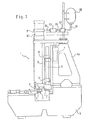
- FIG. 1 illustrated first embodiment of a device 1 according to the invention is constructed on a stator base 6, as it comes in transfer lines used.
- a frame-like upright upper part 6a is placed, which carries a guide assembly 8 in the form of a vertical straight guide.
- a guide assembly 8 in the form of a vertical straight guide.
- On the vertical linear guide is mounted on guide plates 10 and 11, a movable frame 14 which is raised or lowered via a lifting device 7 attached to the upper frame part 6a.
- the movable frame 14 in turn carries a power transmission device 5, which carries a stationary, ie on the movable frame 14 directly attached expanding jaws 3 and a movable expanding jaws 4.
- this power transmission device 5 comprises a in Fig. 2 illustrated expanding wedge 55.
- the arrangement is such that the stationary and the movable expansion jaws of the spreader 5 via the lifting device 7 and the movable frame 14 in the large Eye of a arranged in a holder on the upper part of the stand, consisting of cap and rod connecting rod 2 can be sunk from above or pulled out of this again.
- the piston-cylinder unit 61 in Fig. 1 shown, comprises a piston 9 which is connected via a push rod 19 with an expanding wedge 55. Between the force accumulator 60 and the piston-cylinder unit 61, a safety device 62 and a control valve 63 are arranged. The safety device 62 and the control valve 63 are connected with each other and with respect to the energy accumulator 60 and the piston-cylinder unit 61 with the shortest possible connecting lines 64, 65 and 66 with low hydraulic resistance.
- the safety device 62 is a commercially available unit having a shut-off valve and a pressure relief valve.
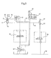
- FIG. 3 shown hydraulic scheme, which is based on the first embodiment, shows a piston-cylinder unit 61 with a piston 9, which divides the piston-cylinder unit 61 into an actuating chamber 85 and a return chamber 86.
- the hydraulic diagram also shows the energy accumulator 60, which communicates with the safety unit 62, which has a shut-off valve and a pressure relief valve in a known manner.
- control valve 63 is connected via a line 65, which in turn communicates via the line 66 with the actuating chamber 85 in connection.
- the arrangement further comprises a main pump 67, with which a hydraulic medium for establishing a storage force via the line 65 and the safety device 62 can be fed into the energy accumulator 60.
- the arrangement further includes a directional control valve 82, with which the control valve 63 can be controlled.
- the hydraulic diagram shows a compressed air line 90, which is connected through the line 91 via a directional control valve 88 and a check valve 89 to the return chamber 86. Furthermore, a discharge device 87 is provided between the directional control valve 88 and the return chamber 86.
- the process now proceeds as follows: First, the energy accumulator 60 is brought via the main pump 67 to its operating pressure. Subsequently, the directional control valve 82 opens the control valve 63. Before or at the same time as this process, the discharge device 87 is opened. Since the control valve 63 is designed such that it releases a relatively large fürströmquerwolves within a very short period of time, which can in the energy storage 60th stored hydraulic medium via the lines 64, 65 and 66 abruptly flow into the actuating chamber 85 of the piston-cylinder unit 61 and thus abruptly transmit a force to a first side of the piston 9, which in turn cooperates with the power transmission device 5. Since the discharge device 87 is opened, this movement of the piston 9 is opposed no significant resistance, so that the released force can be transmitted directly and suddenly via the power transmission device.
- the directional control valve 82 opens a discharge device of the actuation chamber and at the same time opens the directional control valve 88, the connection of the return chamber 86 with a compressed air line 90.
- the fed under pressure air transmits a force to a second side of the piston 9. This raises the Piston 9 back to its original position and the power transmission process on the workpiece can be performed again.
Abstract
Description
Die Erfindung betrifft eine Vorrichtung zum Aufbringen einer Arbeitskraft auf ein Werkstück, um das Werkstück herzustellen oder zu bearbeiten.The invention relates to a device for applying a working force to a workpiece in order to produce or process the workpiece.
In der Technik sind Vorrichtungen gut bekannt, die aus einer Kolben-Zylinder-Einheit mit einem Arbeitszylinder, sowie mit einem Arbeitskolben bestehen. Der Arbeitskolben teilt dabei den Arbeitszylinder in eine Betätigungs-und Rückführungskammer. Bekannt ist, dass sowohl die Betätigungskammer, als auch die Rückführungskammer mit einem Hydraulikmedium beaufschlagbar sind. Die Arbeitskraft wird dabei durch ein Zusammenwirken zwischen dem Arbeitskolben und einer Kraftübertragungseinrichtung auf das Werkstück übertragen.Devices are well known in the art, which consist of a piston-cylinder unit with a working cylinder, as well as with a working piston. The working piston divides the working cylinder into an actuating and return chamber. It is known that both the actuating chamber and the return chamber can be acted upon by a hydraulic medium. The worker is transferred by an interaction between the working piston and a power transmission device on the workpiece.
Das europäische Patent
Es ist bekannt, dass die Qualität von Bruchtrennergebnissen beim Bruchtrennen von Pleueln unter Anderem von der Geschwindigkeit des Trennvorganges abhängt. Aus diesem Grund ist bei der vorstehenden bekannten Verfahrensweise und Vorrichtung bereits vorgeschlagen worden, das Steuerventil als Cartridgeventil auszubilden, sowie das Hydraulikmedium vor dem Einspeisen in die Betätigungskammer der Kolbenzylindereinheit in einem Kraftspeicher unter Druck zu setzen.It is known that the quality of fracture separation results in fracture separation of connecting rods depends, among other things, on the speed of the separation process. For this reason, in the above known method and apparatus has already been proposed to form the control valve as a cartridge valve, as well as to set the hydraulic medium before feeding into the actuating chamber of the piston-cylinder unit in a force storage under pressure.
Der Erfindung liegt die Aufgabe zugrunde, eine eingangs geschilderte Vorrichtung derart weiterzubilden, dass bei möglichst einfachem, technischem Aufbau eine möglichst schnelle Übertragung der Arbeitskraft auf ein Werkstück realisiert werden kann.The invention has the object of developing an initially described device such that the simplest possible, technical structure as fast as possible transfer of the work force can be realized on a workpiece.
Diese Aufgabe wird gelöst durch eine Vorrichtung mit einem Arbeitszylinder, einem Arbeitskolben, einer mit einem Hydraulikmedium beaufschlagbaren, auf einer Seite des Kolbens befindlichen Betätigungskammer, einer mit einem gasförmigen Medium beaufschlagbaren, auf der entgegengesetzten Seite des Kolbens befindlichen Rückführungskammer und einer mit dem Arbeitskolben zusammenwirkenden Kraftübertragungseinrichtung.This object is achieved by a device having a working cylinder, a working piston, an actuatable by a hydraulic medium, located on one side of the piston actuating chamber, which can be acted upon with a gaseous medium, located on the opposite side of the piston return chamber and cooperating with the working piston power transmission device ,
Der Erfindung liegt der Gedanke zugrunde, dass das in der Technik übliche in die Rückführungskammer einspeisbare Hydraulikmedium durch ein gasförmiges Medium ersetzt werden kann. Die Verwendung eines gasförmigen Mediums zur Beaufschlagung der Rückführungskammer bietet den Vorteil, dass der Widerstand beim Verdrängen des Mediums aus der Rückführungskammer während des Kraftübertragungsvorgangs reduziert werden kann. Dies hat den Vorteil, dass eine noch schlagartiger ablaufende Arbeitsweise und damit noch wirkungsvollere Übertragung der Arbeitskraft auf ein Werkstück erzielt werden kann.The invention is based on the idea that the usual in the art fed into the recirculation chamber Hydraulic medium can be replaced by a gaseous medium. The use of a gaseous medium to pressurize the recirculation chamber has the advantage that the resistance in displacing the medium from the recirculation chamber during the power transmission process can be reduced. This has the advantage that an even more abrupt running procedure and thus more effective transmission of the work force can be achieved on a workpiece.
Vorteilhafte Ausführungsformen sind durch die Ansprüche 2-6 gekennzeichnet.Advantageous embodiments are characterized by the claims 2-6.
So steht ein Kraftspeicher mit der Betätigungskammer in Verbindung, sodass das in die Betätigungskammer einspeisbare Hydraulikmedium in dem Kraftspeicher unter Druck speicherbar ist. Diese Ausführungsform besitzt den Vorteil, die Arbeitsweise der Vorrichtung derart schnell zu gestalten, dass eine möglichst schlagartig ablaufende Arbeitsweise erzielt werden kann. Als Kraftspeicher kann ein solcher zum Einsatz kommen, der einen Hochdruckbehälter umfasst, dessen Innenraum über eine Trennmembran in zwei Kammern unterteilt ist, von denen die untere Kammer mit Hydraulikmedium und die obere Kammer mit einem Druckgas, vorzugsweise Stickstoff gefüllt ist.Thus, an energy accumulator communicates with the actuation chamber, so that the hydraulic medium which can be fed into the actuation chamber can be stored under pressure in the energy accumulator. This embodiment has the advantage of making the operation of the device so fast that a sudden as possible operation can be achieved. As an energy storage such can be used, comprising a high-pressure vessel whose interior is divided by a separation membrane into two chambers, of which the lower chamber is filled with hydraulic medium and the upper chamber with a pressurized gas, preferably nitrogen.
Nach einer vorteilhaften Ausführungsform ist zwischen dem Kraftspeicher und der Betätigungskammer ein Steuerventil angeordnet, wobei das im Kraftspeicher unter Druck gespeicherte Hydraulikmedium über das Steuerventil schlagartig in die Betätigungskammer einspeisbar ist. Ein derartiges Steuerventil kann in jeder beliebigen Weise ausgestaltet sein. Wesentlich ist lediglich, dass das Steuerventil derart konzipiert ist, dass innerhalb einer kurzen Zeitspanne, d.h. schlagartig ein relativ großer Durchströmquerschnitt für das Hydraulikmedium zur Verfügung steht, damit das im Kraftspeicher gespeicherte Hydraulikmedium möglichst schlagartig in die Betätigungskammer eingespeist werden kann. Vorteilhaft ist es deshalb, wenn als Steuerventil ein sogenanntes Zwei-Wege-Einbauventil eingesetzt wird. Derartige Ventile werden in der Fachwelt häufig auch als Cartridgeventile bezeichnet.According to an advantageous embodiment, a control valve is arranged between the energy accumulator and the actuation chamber, wherein the hydraulic medium stored under pressure in the energy accumulator can be fed abruptly into the actuation chamber via the control valve. Such a control valve can be configured in any way. It is only essential that the control valve is designed so that within a short period of time, ie abruptly a relatively large flow area for the hydraulic medium is available, so that stored in the energy storage Hydraulic medium can be fed as suddenly as possible in the actuation chamber. It is therefore advantageous if a so-called two-way cartridge valve is used as the control valve. Such valves are often referred to in the art as cartridge valves.
Nach einer bevorzugten Ausführungsform handelt es sich bei dem Werkstück um ein Pleuel und die Kraftübertragungseinrichtung ist derart gestaltet, dass das Pleuel bruchtrennbar ist. Dies hat den Vorteil, dass bei möglichst einfachem, technischem Aufbau ein möglichst schneller Bruchtrenn-Vorgang realisiert werden kann. Des Weiteren wird durch diese Arbeitsweise beim Bruchtrenn-Vorgang eine relativ geringe plastische Verformung des Pleuelmaterials im Bereich der Bruchebene sichergestellt, die einem sogenannten Sprödbruch sehr nahe kommt.According to a preferred embodiment, the workpiece is a connecting rod and the power transmission device is designed such that the connecting rod is fracture-breakable. This has the advantage that the fastest possible fracture separation process can be realized with the simplest possible technical structure. Furthermore, this operation during the fracture separation process ensures a relatively small plastic deformation of the connecting rod material in the region of the fracture plane, which comes very close to a so-called brittle fracture.
Nach einer weiteren Ausführungsform umfasst die Kraftübertragungseinrichtung einen ortsfesten Spreizbacken, einen beweglichen Spreizbacken, sowie eine Spreizeinrichtung in Form eines Spreizkeils zum Auseinanderdrücken der Spreizbacken.According to a further embodiment, the power transmission device comprises a stationary expansion jaws, a movable expanding jaws, as well as a spreading device in the form of an expanding wedge for pushing apart the expanding jaws.
Vorteilhafterweise umfasst die Rückführungskammer zusätzlich eine Ablassvorrichtung, sodass das gasförmige Medium aus der Rückführungskammer schlagartig verdrängbar ist. Eine derartige Ablassvorrichtung kann beispielsweise als Abflussventil mit einem großen Steuerquerschnitt ausgebildet sein, sodass dem unter Druck in die Betätigungskammer eingespeisten Hydraulikmedium auf Seite der Rückführungskammer ein möglichst geringer Gegendruck entgegenwirkt. Vorteilhaft ist es in diesem Zusammenhang, wenn die Steuerung derart gestaltet ist, dass die Ablassvorrichtung bereits geöffnet ist, wenn das unter Druck stehende Hydraulikmedium in die Betätigungskammer eingespeist wird.Advantageously, the return chamber additionally comprises a discharge device, so that the gaseous medium from the return chamber is suddenly displaced. Such a discharge device may be formed for example as a drain valve with a large control cross-section, so that counteracts the under pressure in the actuating chamber fed hydraulic medium on the side of the return chamber as low as possible back pressure. It is advantageous in this context if the controller is designed such that the discharge device is already open when the pressurized hydraulic medium is fed into the actuation chamber.
Nachfolgend wird die Erfindung rein beispielhaft anhand der beigefügten Figuren beschrieben:
- Fig. 1
- zeigt schematisch ein erstes Ausführungsbeispiel einer erfindungsgemäßen Vorrichtung in einer vereinfachten Gesamtansicht;
- Fig. 2
- zeigt in vergrößertem Maßstab eine teilweise geschnittene Ansicht eines Teiles des in
Fig. 1 dargestellten Ausführungsbeispiels; - Fig. 3
- zeigt schematisch ein Hydraulikschema wie es dem ersten Ausführungsbeispiel der erfindungsgemäßen Vorrichtung zugrunde liegt.
- Fig. 1
- shows schematically a first embodiment of a device according to the invention in a simplified overall view;
- Fig. 2
- shows in enlarged scale a partially sectioned view of a part of the in
Fig. 1 illustrated embodiment; - Fig. 3
- schematically shows a hydraulic scheme as it is based on the first embodiment of the device according to the invention.
Das in
Die Anordnung ist derart getroffen, dass der ortsfeste und der bewegliche Spreizbacken der Spreizeinrichtung 5 über die Hubeinrichtung 7 und den beweglichen Rahmen 14 in das große Auge eines in einer Halterung auf dem Ständeroberteil angeordneten, aus Kappe und Stange bestehenden Pleuels 2 von oben eingesenkt bzw. aus diesem wieder herausgezogen werden kann.The arrangement is such that the stationary and the movable expansion jaws of the
Der genaue Aufbau der Kraftübertragungseinrichtung ergibt sich aus
Die Kolbenzylindereinheit 61, in
Die Sicherheitseinrichtung 62 stellt eine handelsübliche Einheit dar, die ein Absperrventil und ein Überdruckventil aufweist.The
Das in
Mit der Sicherheitseinrichtung 62 ist über eine Leitung 65 das Steuerventil 63 verbunden, welches seinerseits über die Leitung 66 mit der Betätigungskammer 85 in Verbindung steht.With the
Wie aus
Die Anordnung enthält darüber hinaus ein Wegeventil 82, mit dem das Steuerventil 63 gesteuert werden kann.The arrangement further includes a
Ferner zeigt das Hydraulikschema eine Druckluftleitung 90, die durch die Leitung 91 über ein Wegeventil 88 und ein Rückschlagventil 89 mit der Rückführungskammer 86 verbunden ist. Des Weiteren ist zwischen dem Wegeventil 88 und der Rückführungskammer 86 eine Ablassvorrichtung 87 vorgesehen.Furthermore, the hydraulic diagram shows a
Der Vorgang läuft nun wie folgt ab: Zuerst wird der Kraftspeicher 60 über die Hauptpumpe 67 auf seinen Betriebsdruck gebracht. Im Anschluss daran öffnet das Wegeventil 82 das Steuerventil 63. Vor oder zeitgleich zu diesem Vorgang wird die Ablassvorrichtung 87 geöffnet. Da das Steuerventil 63 derart gestaltet ist, dass es innerhalb einer sehr kurzen Zeitspanne einen relativ großen DurchströmQuerschnitt freigibt, kann das im Kraftspeicher 60 gespeicherte Hydraulikmedium über die Leitungen 64, 65 und 66 schlagartig in die Betätigungskammer 85 der Kolbenzylindereinheit 61 fließen und damit schlagartig eine Kraft auf eine erste Seite des Kolbens 9 übertragen, welcher wiederum mit der Kraftübertragungseinrichtung 5 zusammenwirkt. Da die Ablassvorrichtung 87 geöffnet ist, wird dieser Bewegung des Kolbens 9 kein nennenswerter Widerstand entgegengesetzt, sodass die freiwerdende Kraft direkt und schlagartig über die Kraftübertragungseinrichtung übertragen werden kann.The process now proceeds as follows: First, the
Ist der Kraftübertragungsvorgang abgeschlossen, so öffnet das Wegeventil 82 eine Ablassvorrichtung der Betätigungskammer und zeitgleich öffnet das Wegeventil 88 die Verbindung der Rückführungskammer 86 mit einer Druckluftleitung 90. Die unter Druck eingespeiste Luft überträgt eine Kraft auf eine zweite Seite des Kolbens 9. Dadurch stellt sich der Kolben 9 in seine Ausgangsstellung zurück und der Kraftübertragungsvorgang auf das Werkstück kann erneut durchgeführt werden.When the power transmission operation is completed, the
Auf diese Weise läuft der Kraftübertragungsvorgang derart schnell ab, dass eine Arbeitsweise gewährleistet ist, die einer mit Schlagmasse arbeitenden Vorrichtung sehr nahe kommt. Es wird deshalb mit Vorrichtungen der erfindungsgemäßen Art ein hinsichtlich der Qualität hochwertiges Kraftübertragungsergebnis mit relativ geringem technischen Aufwand erreicht.In this way, the power transmission process takes place so quickly that an operation is ensured, which comes very close to a working with impact mass device. It is therefore achieved with devices of the type according to the invention in terms of quality high-quality power transmission result with relatively little technical effort.
Claims (6)
- Device for applying a working power to a workpiece, comprising
a working cylinder,
a working piston (9),
an actuating chamber (85) which can be supplied with a hydraulic medium and situated on one side of the piston, and a force transmitting device (5) cooperating with the working piston (9),
characterised by a return chamber (86), which can be supplied with a gaseous medium, situated on the opposite side of the piston. - Device according to claim 1, characterised in that the accumulator (60) communicates with the actuating chamber (85), wherein the hydraulic medium may be stored in the accumulator (60) under pressure.
- Device according to claim 2, characterised in that arranged between the accumulator (60) and the actuating chamber (85) is a control valve (63), wherein the hydraulic medium stored in the accumulator (60) under pressure may be fed instantaneously via the control valve (63) into the actuating chamber (85).
- Device according to claims 1 to 3, characterised in that the workpiece is a connecting rod (2) and the force transmitting device (5) is designed such that the workpiece (2) can be crack split.
- Device according to claim 4, characterised in that the force transmitting device (5) has a locally fixed spreading jaw (3), a movable spreading jaw (4) and a spreading device in the form of a spreading wedge (55) for pushing apart the spreading jaws (3, 4).
- Device according to claims 1 to 5, characterised in that the return chamber (86) includes a discharge device (87) designed such that the gaseous medium may be displaced instantaneously from the return chamber (86).
Applications Claiming Priority (3)
| Application Number | Priority Date | Filing Date | Title |
|---|---|---|---|
| DE2002115952 DE10215952A1 (en) | 2002-04-11 | 2002-04-11 | Device for applying a worker to a workpiece |
| DE10215952 | 2002-04-11 | ||
| PCT/EP2003/002320 WO2003084704A1 (en) | 2002-04-11 | 2003-03-06 | Method for applying a working force to a workpiece |
Publications (2)
| Publication Number | Publication Date |
|---|---|
| EP1492640A1 EP1492640A1 (en) | 2005-01-05 |
| EP1492640B1 true EP1492640B1 (en) | 2009-12-02 |
Family
ID=28684942
Family Applications (1)
| Application Number | Title | Priority Date | Filing Date |
|---|---|---|---|
| EP20030745761 Expired - Lifetime EP1492640B1 (en) | 2002-04-11 | 2003-03-06 | Method for applying a working force to a workpiece |
Country Status (8)
| Country | Link |
|---|---|
| US (1) | US7494034B2 (en) |
| EP (1) | EP1492640B1 (en) |
| JP (1) | JP2006513034A (en) |
| CN (1) | CN100415423C (en) |
| AT (1) | ATE450334T1 (en) |
| DE (2) | DE10215952A1 (en) |
| ES (1) | ES2335655T3 (en) |
| WO (1) | WO2003084704A1 (en) |
Families Citing this family (7)
| Publication number | Priority date | Publication date | Assignee | Title |
|---|---|---|---|---|
| JP2005036902A (en) * | 2003-07-16 | 2005-02-10 | Honda Motor Co Ltd | Dividing method of connecting rod and its dividing device |
| JP2005074537A (en) * | 2003-08-28 | 2005-03-24 | Honda Motor Co Ltd | Connecting rod dividing method and dividing device |
| DE102005043367B4 (en) * | 2005-09-12 | 2016-09-08 | Laeis Gmbh | Control device and control method for a piston-cylinder arrangement |
| ES2399376T3 (en) * | 2009-03-16 | 2013-04-01 | Alfing Kessler Sondermaschinen Gmbh | Procedure to assemble two components of a piece |
| JP5703991B2 (en) * | 2011-06-24 | 2015-04-22 | スズキ株式会社 | Connecting rod fracture splitting method and apparatus |
| CN203581987U (en) * | 2013-10-12 | 2014-05-07 | 富鼎电子科技(嘉善)有限公司 | Separating device |
| CN106005084B (en) * | 2016-07-12 | 2019-01-15 | 天津优瑞纳斯液压机械有限公司 | Hydraulic climbing level robot and its working method |
Family Cites Families (13)
| Publication number | Priority date | Publication date | Assignee | Title |
|---|---|---|---|---|
| FR1589015A (en) | 1968-10-09 | 1970-03-16 | ||
| JPS523985A (en) | 1975-06-26 | 1977-01-12 | Toshiba Mach Co Ltd | Cylinder using two kinds of fluid |
| US4754906A (en) | 1987-03-11 | 1988-07-05 | Mts Systems Corporation | System for manufacturing connecting rods |
| DE9210167U1 (en) | 1992-07-29 | 1992-09-24 | Alfing Kessler Sondermaschinen Gmbh, 7080 Aalen, De | |
| EP0661125B1 (en) * | 1993-12-23 | 1998-05-06 | Alfing Kessler Sondermaschinen GmbH | Apparatus for fracturing connecting rods |
| US5503317A (en) * | 1994-03-31 | 1996-04-02 | Tri-Way Machine Ltd. | Apparatus for fracturing connecting rods preforms |
| US6386417B1 (en) * | 1994-03-25 | 2002-05-14 | Tri-Way Manufacturing Technologies | Method and apparatus for fracturing connecting rods and the like |
| DE19624385B4 (en) | 1996-06-19 | 2006-01-19 | Alfing Kessler Sondermaschinen Gmbh | Device for fracture cutting of connecting rods |
| DE19758583C2 (en) * | 1997-08-01 | 2002-05-08 | Kessler Kg Maschf | Device for breaking an annular component |
| DE19928540A1 (en) * | 1999-04-30 | 2000-11-09 | Guenter Diehm | Hydraulic positioning device has cylinder-adjustment piston unit, where piston separates cylinder into air and oil filled chambers |
| JP3642268B2 (en) * | 2000-08-24 | 2005-04-27 | 株式会社安永 | Connecting rod breaking device |
| DE10122249B4 (en) | 2001-05-08 | 2005-06-16 | Alfing Kessler Sondermaschinen Gmbh | Method and device for machining ring-like workpieces |
| DE602005005010T2 (en) * | 2005-02-09 | 2008-06-12 | Vigel S.P.A., Borgaro Torinese | Device for fracture separation of the head bearing of a connecting rod |
-
2002
- 2002-04-11 DE DE2002115952 patent/DE10215952A1/en not_active Ceased
-
2003
- 2003-03-06 US US10/510,122 patent/US7494034B2/en not_active Expired - Fee Related
- 2003-03-06 JP JP2003581933A patent/JP2006513034A/en active Pending
- 2003-03-06 EP EP20030745761 patent/EP1492640B1/en not_active Expired - Lifetime
- 2003-03-06 ES ES03745761T patent/ES2335655T3/en not_active Expired - Lifetime
- 2003-03-06 CN CNB038081482A patent/CN100415423C/en not_active Expired - Fee Related
- 2003-03-06 WO PCT/EP2003/002320 patent/WO2003084704A1/en active Application Filing
- 2003-03-06 DE DE50312188T patent/DE50312188D1/en not_active Expired - Fee Related
- 2003-03-06 AT AT03745761T patent/ATE450334T1/en not_active IP Right Cessation
Also Published As
| Publication number | Publication date |
|---|---|
| US20060130554A1 (en) | 2006-06-22 |
| CN100415423C (en) | 2008-09-03 |
| US7494034B2 (en) | 2009-02-24 |
| ES2335655T3 (en) | 2010-03-31 |
| EP1492640A1 (en) | 2005-01-05 |
| DE10215952A1 (en) | 2003-11-06 |
| CN1646249A (en) | 2005-07-27 |
| WO2003084704A1 (en) | 2003-10-16 |
| DE50312188D1 (en) | 2010-01-14 |
| ATE450334T1 (en) | 2009-12-15 |
| JP2006513034A (en) | 2006-04-20 |
Similar Documents
| Publication | Publication Date | Title |
|---|---|---|
| DE2525391A1 (en) | MACHINE TOOLS, IN PARTICULAR COMBINED PROFILE STEEL SHEARS AND PUNCHING PUNCH | |
| EP1507980B1 (en) | Hydraulic control in a hydraulic system, especially for the operation of scrap cutters | |
| DE8130366U1 (en) | SHOCK ABSORBER DEVICE FOR PRESSES | |
| EP0661125B1 (en) | Apparatus for fracturing connecting rods | |
| EP2848398B1 (en) | Device and method for preventing a tool from breaking during fine cutting and/or forming a work piece | |
| EP1492640B1 (en) | Method for applying a working force to a workpiece | |
| DE3626455A1 (en) | SPINDLE PRESS | |
| DE2940232A1 (en) | HYDRAULIC SHOCK ABSORBER, ESPECIALLY FOR SHEARING PRESSES | |
| DE3935787C2 (en) | ||
| EP3423210B1 (en) | Forging press and method for forging a workpiece in a forging press | |
| DE2916191A1 (en) | POWER UNIT AS A DRIVE DEVICE, e.g. FOR FORMING, DEFORMING, COMPRESSING, HITING AND DRIVING | |
| DE2264429A1 (en) | FINE PUNCH PRESS | |
| DE3241746A1 (en) | DEVICE FOR COUPLING A BORING ROD FOR CHAMBER TAPE HOLES WITH THE WORK TOOL OF A DRILLING MACHINE | |
| DE10005023A1 (en) | Press | |
| DE102009034267A1 (en) | Press and/or die cutter for workpiece, has switch that selectively switches free passage or air regulator in hydraulic circuit that is connected with controller for hydraulic drive | |
| DE3112393C2 (en) | Hydraulic press and a method for its operation | |
| EP3115190A1 (en) | Device and method for controlling the principal drive of a precision cutting press | |
| EP0417752B1 (en) | Mechanical or hydraulic press with drawing or pressing station for multiple stage press | |
| EP0847836A1 (en) | Percussive tool with fluid pressure drive | |
| EP3678985B1 (en) | Positioning device for the relative positioning of a container to be treated and a treatment apparatus in a container treatment facility | |
| DE2213810A1 (en) | PNEUMATICALLY OPERATED RIVETING DEVICE | |
| DE4306396C2 (en) | Device for adjusting the play between guide stands and a bear of a drop forging device | |
| DE2914933C2 (en) | Pressure medium-operated remote control for the main pneumatic control unit of a drop forging hammer, in particular a counter-blow hammer | |
| DE19726314A1 (en) | Hydraulic press unit | |
| DE1959557C3 (en) | Block and slab shears or the like. Machine tools such as presses |
Legal Events
| Date | Code | Title | Description |
|---|---|---|---|
| PUAI | Public reference made under article 153(3) epc to a published international application that has entered the european phase |
Free format text: ORIGINAL CODE: 0009012 |
|
| 17P | Request for examination filed |
Effective date: 20040922 |
|
| AK | Designated contracting states |
Kind code of ref document: A1 Designated state(s): AT BE BG CH CY CZ DE DK EE ES FI FR GB GR HU IE IT LI LU MC NL PT RO SE SI SK TR |
|
| 17Q | First examination report despatched |
Effective date: 20090505 |
|
| GRAP | Despatch of communication of intention to grant a patent |
Free format text: ORIGINAL CODE: EPIDOSNIGR1 |
|
| GRAS | Grant fee paid |
Free format text: ORIGINAL CODE: EPIDOSNIGR3 |
|
| GRAA | (expected) grant |
Free format text: ORIGINAL CODE: 0009210 |
|
| AK | Designated contracting states |
Kind code of ref document: B1 Designated state(s): AT BE BG CH CY CZ DE DK EE ES FI FR GB GR HU IE IT LI LU MC NL PT RO SE SI SK TR |
|
| REG | Reference to a national code |
Ref country code: GB Ref legal event code: FG4D Free format text: NOT ENGLISH |
|
| REG | Reference to a national code |
Ref country code: CH Ref legal event code: EP |
|
| REG | Reference to a national code |
Ref country code: IE Ref legal event code: FG4D |
|
| REF | Corresponds to: |
Ref document number: 50312188 Country of ref document: DE Date of ref document: 20100114 Kind code of ref document: P |
|
| REG | Reference to a national code |
Ref country code: SE Ref legal event code: TRGR |
|
| REG | Reference to a national code |
Ref country code: ES Ref legal event code: FG2A Ref document number: 2335655 Country of ref document: ES Kind code of ref document: T3 |
|
| REG | Reference to a national code |
Ref country code: NL Ref legal event code: VDEP Effective date: 20091202 |
|
| PG25 | Lapsed in a contracting state [announced via postgrant information from national office to epo] |
Ref country code: FI Free format text: LAPSE BECAUSE OF FAILURE TO SUBMIT A TRANSLATION OF THE DESCRIPTION OR TO PAY THE FEE WITHIN THE PRESCRIBED TIME-LIMIT Effective date: 20091202 |
|
| PG25 | Lapsed in a contracting state [announced via postgrant information from national office to epo] |
Ref country code: SI Free format text: LAPSE BECAUSE OF FAILURE TO SUBMIT A TRANSLATION OF THE DESCRIPTION OR TO PAY THE FEE WITHIN THE PRESCRIBED TIME-LIMIT Effective date: 20091202 Ref country code: CY Free format text: LAPSE BECAUSE OF FAILURE TO SUBMIT A TRANSLATION OF THE DESCRIPTION OR TO PAY THE FEE WITHIN THE PRESCRIBED TIME-LIMIT Effective date: 20091202 |
|
| REG | Reference to a national code |
Ref country code: IE Ref legal event code: FD4D |
|
| PG25 | Lapsed in a contracting state [announced via postgrant information from national office to epo] |
Ref country code: RO Free format text: LAPSE BECAUSE OF FAILURE TO SUBMIT A TRANSLATION OF THE DESCRIPTION OR TO PAY THE FEE WITHIN THE PRESCRIBED TIME-LIMIT Effective date: 20091202 Ref country code: BG Free format text: LAPSE BECAUSE OF FAILURE TO SUBMIT A TRANSLATION OF THE DESCRIPTION OR TO PAY THE FEE WITHIN THE PRESCRIBED TIME-LIMIT Effective date: 20100302 Ref country code: EE Free format text: LAPSE BECAUSE OF FAILURE TO SUBMIT A TRANSLATION OF THE DESCRIPTION OR TO PAY THE FEE WITHIN THE PRESCRIBED TIME-LIMIT Effective date: 20091202 Ref country code: IE Free format text: LAPSE BECAUSE OF FAILURE TO SUBMIT A TRANSLATION OF THE DESCRIPTION OR TO PAY THE FEE WITHIN THE PRESCRIBED TIME-LIMIT Effective date: 20091202 Ref country code: PT Free format text: LAPSE BECAUSE OF FAILURE TO SUBMIT A TRANSLATION OF THE DESCRIPTION OR TO PAY THE FEE WITHIN THE PRESCRIBED TIME-LIMIT Effective date: 20100402 Ref country code: NL Free format text: LAPSE BECAUSE OF FAILURE TO SUBMIT A TRANSLATION OF THE DESCRIPTION OR TO PAY THE FEE WITHIN THE PRESCRIBED TIME-LIMIT Effective date: 20091202 |
|
| PG25 | Lapsed in a contracting state [announced via postgrant information from national office to epo] |
Ref country code: SK Free format text: LAPSE BECAUSE OF FAILURE TO SUBMIT A TRANSLATION OF THE DESCRIPTION OR TO PAY THE FEE WITHIN THE PRESCRIBED TIME-LIMIT Effective date: 20091202 |
|
| BERE | Be: lapsed |
Owner name: ALFING KESSLER SONDERMASCHINEN G.M.B.H. Effective date: 20100331 |
|
| PLBE | No opposition filed within time limit |
Free format text: ORIGINAL CODE: 0009261 |
|
| STAA | Information on the status of an ep patent application or granted ep patent |
Free format text: STATUS: NO OPPOSITION FILED WITHIN TIME LIMIT |
|
| PG25 | Lapsed in a contracting state [announced via postgrant information from national office to epo] |
Ref country code: GR Free format text: LAPSE BECAUSE OF FAILURE TO SUBMIT A TRANSLATION OF THE DESCRIPTION OR TO PAY THE FEE WITHIN THE PRESCRIBED TIME-LIMIT Effective date: 20100303 Ref country code: MC Free format text: LAPSE BECAUSE OF NON-PAYMENT OF DUE FEES Effective date: 20100331 |
|
| REG | Reference to a national code |
Ref country code: CH Ref legal event code: PL |
|
| EUG | Se: european patent has lapsed | ||
| 26N | No opposition filed |
Effective date: 20100903 |
|
| GBPC | Gb: european patent ceased through non-payment of renewal fee |
Effective date: 20100306 |
|
| PG25 | Lapsed in a contracting state [announced via postgrant information from national office to epo] |
Ref country code: CZ Free format text: LAPSE BECAUSE OF NON-PAYMENT OF DUE FEES Effective date: 20100306 |
|
| REG | Reference to a national code |
Ref country code: FR Ref legal event code: ST Effective date: 20101130 |
|
| PG25 | Lapsed in a contracting state [announced via postgrant information from national office to epo] |
Ref country code: DK Free format text: LAPSE BECAUSE OF FAILURE TO SUBMIT A TRANSLATION OF THE DESCRIPTION OR TO PAY THE FEE WITHIN THE PRESCRIBED TIME-LIMIT Effective date: 20091202 Ref country code: FR Free format text: LAPSE BECAUSE OF NON-PAYMENT OF DUE FEES Effective date: 20100331 |
|
| PG25 | Lapsed in a contracting state [announced via postgrant information from national office to epo] |
Ref country code: DE Free format text: LAPSE BECAUSE OF NON-PAYMENT OF DUE FEES Effective date: 20101001 Ref country code: CH Free format text: LAPSE BECAUSE OF NON-PAYMENT OF DUE FEES Effective date: 20100331 Ref country code: BE Free format text: LAPSE BECAUSE OF NON-PAYMENT OF DUE FEES Effective date: 20100331 Ref country code: LI Free format text: LAPSE BECAUSE OF NON-PAYMENT OF DUE FEES Effective date: 20100331 |
|
| PG25 | Lapsed in a contracting state [announced via postgrant information from national office to epo] |
Ref country code: IT Free format text: LAPSE BECAUSE OF FAILURE TO SUBMIT A TRANSLATION OF THE DESCRIPTION OR TO PAY THE FEE WITHIN THE PRESCRIBED TIME-LIMIT Effective date: 20091202 Ref country code: GB Free format text: LAPSE BECAUSE OF NON-PAYMENT OF DUE FEES Effective date: 20100306 |
|
| REG | Reference to a national code |
Ref country code: ES Ref legal event code: FD2A Effective date: 20110415 |
|
| PG25 | Lapsed in a contracting state [announced via postgrant information from national office to epo] |
Ref country code: ES Free format text: LAPSE BECAUSE OF NON-PAYMENT OF DUE FEES Effective date: 20110404 |
|
| PG25 | Lapsed in a contracting state [announced via postgrant information from national office to epo] |
Ref country code: AT Free format text: LAPSE BECAUSE OF NON-PAYMENT OF DUE FEES Effective date: 20100306 |
|
| PG25 | Lapsed in a contracting state [announced via postgrant information from national office to epo] |
Ref country code: ES Free format text: LAPSE BECAUSE OF NON-PAYMENT OF DUE FEES Effective date: 20100307 |
|
| PG25 | Lapsed in a contracting state [announced via postgrant information from national office to epo] |
Ref country code: LU Free format text: LAPSE BECAUSE OF NON-PAYMENT OF DUE FEES Effective date: 20100306 Ref country code: SE Free format text: LAPSE BECAUSE OF NON-PAYMENT OF DUE FEES Effective date: 20100307 Ref country code: HU Free format text: LAPSE BECAUSE OF FAILURE TO SUBMIT A TRANSLATION OF THE DESCRIPTION OR TO PAY THE FEE WITHIN THE PRESCRIBED TIME-LIMIT Effective date: 20100603 |
|
| PG25 | Lapsed in a contracting state [announced via postgrant information from national office to epo] |
Ref country code: TR Free format text: LAPSE BECAUSE OF FAILURE TO SUBMIT A TRANSLATION OF THE DESCRIPTION OR TO PAY THE FEE WITHIN THE PRESCRIBED TIME-LIMIT Effective date: 20091202 |