EP2331859B1 - Druckentlastetes kompaktdrehventil - Google Patents
Druckentlastetes kompaktdrehventil Download PDFInfo
- Publication number
- EP2331859B1 EP2331859B1 EP09812565.1A EP09812565A EP2331859B1 EP 2331859 B1 EP2331859 B1 EP 2331859B1 EP 09812565 A EP09812565 A EP 09812565A EP 2331859 B1 EP2331859 B1 EP 2331859B1
- Authority
- EP
- European Patent Office
- Prior art keywords
- stator
- port
- springs
- ports
- rotor
- Prior art date
- Legal status (The legal status is an assumption and is not a legal conclusion. Google has not performed a legal analysis and makes no representation as to the accuracy of the status listed.)
- Active
Links
- 238000000034 method Methods 0.000 claims description 17
- 239000003463 adsorbent Substances 0.000 claims description 16
- 238000001179 sorption measurement Methods 0.000 claims description 11
- 230000003247 decreasing effect Effects 0.000 claims description 2
- 239000007789 gas Substances 0.000 description 17
- 239000012530 fluid Substances 0.000 description 15
- 238000012546 transfer Methods 0.000 description 9
- 230000000052 comparative effect Effects 0.000 description 5
- 238000010438 heat treatment Methods 0.000 description 5
- 238000007789 sealing Methods 0.000 description 5
- 230000008901 benefit Effects 0.000 description 4
- 238000012993 chemical processing Methods 0.000 description 3
- 239000004820 Pressure-sensitive adhesive Substances 0.000 description 2
- 238000013461 design Methods 0.000 description 2
- 239000000463 material Substances 0.000 description 2
- 238000012545 processing Methods 0.000 description 2
- 238000007664 blowing Methods 0.000 description 1
- 238000005516 engineering process Methods 0.000 description 1
- 239000000203 mixture Substances 0.000 description 1
- 238000012986 modification Methods 0.000 description 1
- 230000004048 modification Effects 0.000 description 1
- 238000002407 reforming Methods 0.000 description 1
- 230000003252 repetitive effect Effects 0.000 description 1
- 238000000926 separation method Methods 0.000 description 1
- 230000003068 static effect Effects 0.000 description 1
- 238000012360 testing method Methods 0.000 description 1
Images


Classifications
-
- F—MECHANICAL ENGINEERING; LIGHTING; HEATING; WEAPONS; BLASTING
- F16—ENGINEERING ELEMENTS AND UNITS; GENERAL MEASURES FOR PRODUCING AND MAINTAINING EFFECTIVE FUNCTIONING OF MACHINES OR INSTALLATIONS; THERMAL INSULATION IN GENERAL
- F16K—VALVES; TAPS; COCKS; ACTUATING-FLOATS; DEVICES FOR VENTING OR AERATING
- F16K11/00—Multiple-way valves, e.g. mixing valves; Pipe fittings incorporating such valves
- F16K11/02—Multiple-way valves, e.g. mixing valves; Pipe fittings incorporating such valves with all movable sealing faces moving as one unit
- F16K11/06—Multiple-way valves, e.g. mixing valves; Pipe fittings incorporating such valves with all movable sealing faces moving as one unit comprising only sliding valves, i.e. sliding closure elements
- F16K11/072—Multiple-way valves, e.g. mixing valves; Pipe fittings incorporating such valves with all movable sealing faces moving as one unit comprising only sliding valves, i.e. sliding closure elements with pivoted closure members
- F16K11/074—Multiple-way valves, e.g. mixing valves; Pipe fittings incorporating such valves with all movable sealing faces moving as one unit comprising only sliding valves, i.e. sliding closure elements with pivoted closure members with flat sealing faces
- F16K11/0743—Multiple-way valves, e.g. mixing valves; Pipe fittings incorporating such valves with all movable sealing faces moving as one unit comprising only sliding valves, i.e. sliding closure elements with pivoted closure members with flat sealing faces with both the supply and the discharge passages being on one side of the closure plates
-
- F—MECHANICAL ENGINEERING; LIGHTING; HEATING; WEAPONS; BLASTING
- F16—ENGINEERING ELEMENTS AND UNITS; GENERAL MEASURES FOR PRODUCING AND MAINTAINING EFFECTIVE FUNCTIONING OF MACHINES OR INSTALLATIONS; THERMAL INSULATION IN GENERAL
- F16K—VALVES; TAPS; COCKS; ACTUATING-FLOATS; DEVICES FOR VENTING OR AERATING
- F16K39/00—Devices for relieving the pressure on the sealing faces
- F16K39/04—Devices for relieving the pressure on the sealing faces for sliding valves
- F16K39/045—Devices for relieving the pressure on the sealing faces for sliding valves of rotating or pivoting type
-
- Y—GENERAL TAGGING OF NEW TECHNOLOGICAL DEVELOPMENTS; GENERAL TAGGING OF CROSS-SECTIONAL TECHNOLOGIES SPANNING OVER SEVERAL SECTIONS OF THE IPC; TECHNICAL SUBJECTS COVERED BY FORMER USPC CROSS-REFERENCE ART COLLECTIONS [XRACs] AND DIGESTS
- Y10—TECHNICAL SUBJECTS COVERED BY FORMER USPC
- Y10T—TECHNICAL SUBJECTS COVERED BY FORMER US CLASSIFICATION
- Y10T137/00—Fluid handling
- Y10T137/8593—Systems
- Y10T137/86493—Multi-way valve unit
- Y10T137/86501—Sequential distributor or collector type
Definitions
- the present disclosure concerns pressure balanced rotary valves, particularly for use in pressure swing devices.
- Rotary valves can provide a convenient and compact way of consolidating the multiple valves required for repetitive chemical processing cycles into a single, simple unit.
- rotary valves can be particularly useful in chemical processing operations involving pressure swing devices (e.g. pressure swing adsorption devices, pressure swing reforming devices).
- rotary valves comprise a stator and a rotor that is rotated about its axis relative to the stator. Both stator and rotor contain suitably sized and located ports that function as multiple valves as a result of the rotation of the rotor. Via this rotation, the ports in the rotor come into and out of alignment with ports in the stator, thus opening and closing the ports to fluid flow, and thereby serving as valves. Some means of loading is required to engage the rotor with the stator in order to maintain an adequate seal therebetween. In some applications, a uniform, constant load may provide satisfactory function of the rotary valve. Documents US2613056 , US2861651 , US47371003 and WO02/24309 all disclose different rotary valves.
- the rotary valve comprises axially aligned fluid transfer sleeves (e.g. pistons) which are used to provide a variable load to keep the stator and rotor closed.
- Fluid transfer sleeves may be located in cylinders formed in the stator at the various locations of the stator ports. The sleeves may be sealed to the cylinders using static seals or piston rings.
- Each adsorbent bed in the pressure swing device is connected to one of these ports and thus the fluid pressure in the fluid transfer sleeve is provided by that adsorbent bed fluidly connected to it.
- a variable load is thus provided at each port in the stator and this load is a function of the pressure in the adsorbent bed and of the axial area of the fluid transfer sleeve.
- mechanical springs provide a fixed load to the stator via the fluid transfer sleeves (e.g. springs are located beneath the fluid transfer sleeves and assist the sleeves to urge the stator against the rotor).
- the ports in both stator and rotor may be located on a port pitch circle that is centered on the rotor axis.
- the operating parameters required of the device e.g. flow rates, pressures, and the like
- the relatively large piston size typically limits the minimum port pitch circle that can be used.
- the relatively smaller stator ports wind up spaced apart such that the spacings between stator ports are greater than the size of the ports themselves.
- the typical rotary valve pressure swing adsorption device employs two rotary valves, one connected to the feed ends of the adsorbent beds where the gas mixtures to be separated are provided, and another connected to the product ends of the adsorbent beds where separated product gases are obtained.
- the port geometries in the stators and rotors i.e. size, shape, and spacing
- the port geometries in the stators and rotors are typically chosen to optimize the process cycle for a given gas separation application. However, this too would generally include choosing a design in which the port spacings on the stator are greater in size than the ports themselves. On the product end of the device, this has been an essential requirement. This is because the ports in the rotor (which are typically as big or bigger than those in the stator) would otherwise interconnect adjacent stator ports over portions of the rotation cycle and thus cause an unacceptable bridging of gases between these adjacent stator ports.
- the rotary valves In a given chemical processing application, if greater processing throughput is desired, the rotary valves must be designed to handle greater gas flows and hence employ larger ports. Conventionally, this means the rotary valve diameter would be increased accordingly to accommodate the greater port size. Also, the size of the fluid transfer sleeves or pistons must be increased accordingly to provide a greater possible variable load for pressure balancing purposes.
- stator port spacings that are less than the port size and still maintain acceptable process cycle function and an acceptable loading between the rotor and stator.
- stator port spacing may be reduced such that some bridging of gases occurs here during the process cycle. That is, the spacings between ports in the rotary valve may be made less than the size of the ports themselves.
- variable pressure balancing sleeves or pistons it can be acceptable to reduce the size of the variable pressure balancing sleeves or pistons, and hence the variable load they provide, while increasing the mechanically provided fixed load to compensate.
- the piston size no longer need dictate the minimum port pitch circle that is used. With these two limitations relaxed, it is possible to increase the port size and hence the throughput of a rotary valve without a conventional increase in the overall size of the valve.
- Such a compact rotary valve comprises a stator comprising at least two ports centred on a port pitch circle, in which each port provides an opening over an open arc length around the port pitch circle and thereby defines port spacings between the ports over closed arc lengths around the port pitch circle.
- the compact rotary valve also comprises a rotor rotating about a rotor axis at the centre of the port pitch circle and comprising at least two ports centred on the port pitch circle, variable loading means to sealingly engage the rotor to the stator, fixed loading means to sealingly engage the rotor to the stator, and drive means to rotate the rotor about the rotor axis relative to the stator such that the ports in the rotor come into and out of alignment with the ports in the stator.
- the compact rotary valve is characterized in that the minimum closed arc length of a port spacing in the stator is less than the maximum open arc length of a port opening.
- the stator may typically comprise a plurality of ports.
- a variety of port shapes may be employed but, in particular the stator ports may be circular.
- Various port sizes may also be employed, but in particular the stator ports may be essentially the same size.
- the stator ports may be spaced equidistant around the port pitch circle in which case, all the closed arc lengths of the port spacings are essentially equal and all the open arc lengths of the ports are essentially equal. Also, in this instance, the closed arc length of all the port spacings will be less than the open arc length of all the port openings.
- variable loading means employed in the rotary valve can comprise pistons located adjacent each port in the stator in order to provide a variable load to the stator in accordance with gas pressure received at that port. These pistons may be centred on the port pitch circle.
- the fixed loading means in the rotary valve can comprise springs to provide a fixed load to the stator.
- the springs can be located outside the pistons.
- there may be two sets of springs a first set located on a first spring pitch circle larger than the port pitch circle, and a second set is located on a second spring pitch circle smaller than the port pitch circle.
- the force provided by the second set of springs may be chosen to be less than that applied by the first set of springs. This can be accomplished by selecting springs in which the spring constant of the second set of springs is smaller than that of the first set of springs.
- the rotary valve is suitable for use in a rotary pressure swing device such as a pressure swing adsorption (PSA) device, and particularly at the feed end.
- PSA pressure swing adsorption
- the adsorbent beds in the PSA device generally are the sources of gas pressure received at the ports in the stator.
- the variable and fixed pressures (or forces) may be modified such that the average contact pressure between the rotor and the stator during operation is greater than 407 kPa (59 psi), and/or such that the springs provide more than 10% of the total loading force applied to the stator by the pistons and springs.
- Contact pressure is the net local pressure of the two surfaces in contact.
- the invention thus represents a method of reducing the size of a rotary valve in a pressure swing device (e.g. a PSA device).
- the method comprises decreasing the port pitch circle diameter such that the minimum closed arc length of a stator port spacing is less than the maximum open arc length of a stator port opening and thereby accepting the result that there is a bridging of the ports during at least a portion of the pressure swing adsorption cycle.
- the method can comprise reducing the size of the pistons and increasing the load provided by the springs such that the average contact pressure between the rotor and the stator during operation is increased above 407 kPa (59 psi), and/or such that the springs provide more than 10% of the total loading force to the stator.
- feed end rotary valve 1 includes stator 2 and rotor 3 which each comprise several ports centred on stator and rotor pitch circles respectively.
- stator 2 comprises nine circular ports spaced equidistant around the stator port pitch circle (i.e. 40 degrees apart). Each of these ports then fluidly connects to the feed end of one of nine corresponding adsorbent beds in the PSA device.
- One stator port 4 is shown in Figure 1 which fluidly connects via conduit 10 (formed in stator 1) to the feed end of an adsorbent bed (not shown).
- Rotor 3 comprises two oblong function ports spaced approximately 180 degrees apart on the rotor port pitch circle. One port is used to supply feed gas to more than one adsorbent bed at a time, while the other is used to exhaust blowdown gas from more than one adsorbent bed at a time during the PSA cycle.
- Feed gas rotor port 5 is shown in Figure 1 and fluidly connects to the feed gas supply (not shown) via conduit 6 in rotor 3 and via conduit 11 formed in stator 2.
- the other blowdown rotor port 14 is fluidly connected to the volume 15 surrounding rotor 3, which in turn is fluidly connected to conduit 9 for blowdown exhaust.
- Stator port 4 and rotor port 5 are aligned in Figure 1 and thus feed gas would be being supplied to that adsorbent bed connected to conduit 10.
- Rotary valve 1 additionally comprises variable loading means for pressure balancing purposes. This is provided by pistons 7 which are located adjacent the stator ports and which force stator 2 towards rotor 3 in accordance with the fluid pressure inside the piston (e.g. the gas pressure in conduit 10 for piston 7 illustrated in Figure 1 ).
- Rotary valve 1 also comprises fixed loading means which are provided in part by mechanical springs 8 which are seated within pistons 7 in this embodiment. However, fixed loading means are also provided in the embodiment shown at the centre of stator 2 via piston 12 and via mechanical spring 13. The force provided by piston 12 is a function of the feed gas pressure in conduit 11 and thus is fixed if the feed gas pressure is fixed.
- drive means for rotor 3 is provided by shaft 20, and a drive motor (not shown).
- Figures 2b and 3b illustrate this situation in plan views of the seal side and the back side respectively of stator 2 in Figure 1 .
- Ports 4 are centred on and spaced equidistant around stator port pitch circle 2a.
- the open arc length of a port opening 2b is significantly smaller than the closed arc length of a port spacing 2c.
- piston sleeves 16 (and pistons 7) are also centred on port pitch circle 2a and, as shown in Fig. 3b , are spaced essentially as close as possible already.
- the overall diameter of stator 2 cannot be reduced.
- the diameter of port pitch circle 2a can in principle be reduced by offsetting the port centres with respect to those of the pistons, but even then, only to a very small extent.
- Figures 2a and 3a depict plan views of the seal side and back side respectively of a stator for a rotary valve of the invention.
- like numerals have been employed here for like features to those in Figures 1 , 2b and 3b .
- the size of the variable load pistons 7 has been reduced and hence so has the diameter of sleeves 16.
- the fixed force provided has to be relatively increased.
- the benefit is that now either the port pitch circle diameter can be reduced (thus reducing the valve size) or alternatively, the size of ports 4 can be increased (thus increasing the processing capability of the PSA, as is the case shown in Figures 2a and 3a ).
- Figure 3a shows locations 17 and 18 for first and second sets of springs respectively that are outside of pistons 7.
- Locations 17 for the first spring set are on a first pitch circle of greater diameter than port pitch circle 2a.
- Locations 18 for the second spring set are on a second pitch circle of lesser diameter than port pitch circle 2a.
- the second set of springs applies less closing force to stator 2 than does the first set of springs for better balancing. This can be achieved either by using springs with a smaller spring constant for the second set or alternatively by using shorter springs (and thereby compressing less) for the second set.
- rotary valves of the invention have relatively smaller pistons 7 for a given valve size and thus require relatively more fixed loading to compensate for the reduction in the variable loading provided.
- the fixed loading means e.g. springs 8
- the fixed loading means thus provide more of the conventional total loading force and can, for instance, be providing more than 10% of the total loading force.
- the average contact pressure between stator 2 and rotor 3 is increased over that of conventional rotary valves. We have found that the satisfactory operation of a rotary valve can still be achieved when the average contact pressure during operation is greater than 407 kPa (59 psi).
- a series of rotary valves were designed and built for use in rotary PSA devices of varying flow range capability.
- the table below lists the pertinent mechanical characteristics of these rotary valves.
- three different size valves are listed and include comparative valves for the feed sides in both a relatively small PSA and a midsize PSA, and finally an inventive valve for the feed side of the relatively large PSA.
- the PSAs comprised 9 adsorbent beds.
- the stator for the inventive feed valve in the large PSA is illustrated in Figs. 2a and 3a .
- the stator for the comparative feed valve in the midsize PSA is illustrated in Figs. 2b and 3b .
- variable loading to sealingly engage the stator to the rotor is provided by pistons in accordance with the gas pressure in the adsorbent beds.
- the fixed loading is mainly provided by springs located within these pistons or just outside the pistons as shown in Figs. 2 and 3 .
- some additional fixed force was also provided in some embodiments by a central spring and/or piston as shown in Fig 1 .
- Rotary valve Characteristic Inventive for feed valve in large PSA Comparative for feed valve in midsize PSA Comparative for feed valve in small PSA Feed pressure (psig) 300 300 175 Stator port diameter (inches) 2.4 0.75 0.28 Stator port pitch circle diameter (inches) 11.8 5.3 3.4 Stator port arc length (inches) 2.40 0.751 0.280 Stator port spacing arc length (inches) 1.71 1.10 0.907 (Port diameter)/(port pitch circle diameter) 20% 14% 8% Piston diameter (inches) 3.5 1.8 1 # springs in or near pistons 18 9 9 Fraction of closing force provided by pistons 50% 93% 63% Fraction of closing force provided by springs 50% 7% 37% Average contact pressure between stator and rotor (psi) 81 59 24 (Average contact pressure)/(feed pressure) 27% 20% 14%
- the port pitch circle diameter was reduced with respect to the port size such that the stator port spacing arc length was less than the arc length of the port openings. This allows for a smaller overall valve size but requires a smaller piston size (relative to convention) in order to achieve it. In turn, this results in less variable loading capability and thus a requirement for greater fixed loading to compensate.
- the ratio of the (port diameter)/(port pitch circle diameter) is indicative of how much the valve has been reduced in size with regards to the port size.
- the fraction of the closing force provided by each of the pistons and springs is indicative of how much the fixed load has been increased to compensate.
- the springs now provide more than 10% of the total closing force. (Note that this is also the situation in the smaller valve in the comparative small PSA application as well. However, this % would generally decrease with valve size using prior art design principles.)
- the average contact pressure shows how much the loading between stator and rotor has been increased overall, on average.
- the inventive feed valve would now operate at an average of 558 kPa (81 psi) (significantly >407 kPa (59 psi)) in this application.
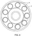
- Fig. 4 qualitatively shows the calculated (using finite element analysis) pressure distribution at 60 °C for the seal side surface ( Fig. 2a ) of the stator in the large inventive feed valve stator.
- the darkest shading represents the highest contact pressure.
- the lightest shading represents intermediate contact pressure and primarily surrounds those ports in the area at 3-6 o'clock in Fig. 4 . The ports in this area are attached to the feed and thus experience more force blowing the seal apart.
- the intermediate shading represents the lightest contact pressure (primarily surrounding the centre feed port and on the outside perimeter of the valve). The analysis shows almost full, uniform contact of the seal even at this elevated temperature.
Landscapes
- Engineering & Computer Science (AREA)
- General Engineering & Computer Science (AREA)
- Mechanical Engineering (AREA)
- Multiple-Way Valves (AREA)
Claims (14)
- Druckwechseldrehvorrichtung, umfassend ein Drehventil (1), umfassend:einen Stator (2), der mindestens zwei Anschlüsse (4) umfasst, die auf einem Anschlusskreis (2a) zentriert sind, und wobei jeder Anschluss (4) eine Öffnung über einer offenen Bogenlänge um den Anschlusskreis (2a) herum bereitstellt und dadurch Anschlussabstände (2c) zwischen den Anschlüssen (4) über geschlossene Bogenlängen um den Anschlusskreis (2a) herum definiert werden;einen Rotor (3), der um eine Rotorachse im Zentrum des Anschlusskreises (2a) rotiert und mindestens zwei Anschlüsse umfasst, die auf dem Anschlusskreis (2a) zentriert sind;variable Belastungsmittel, um den Rotor (3) mit dem Stator (2) in einen abdichtenden Eingriff zu bringen;feste Beladungsmittel, um den Rotor (3) mit dem Stator (2) in einen abdichtenden Eingriff zu bringen; undAntriebsmittel, um den Rotor (3) relativ zu dem Stator (2) um die Rotorachse zu drehen, so dass die Anschlüsse in dem Rotor (3) mit den Anschlüssen (4) in dem Stator (2) in eine Ausrichtung und aus einer Ausrichtung gebracht werden;wobei die minimale geschlossene Bogenlänge der Anschlussabstände (2c) geringer als die maximale offene Bogenlänge der Anschlussöffnungen (2b) ist.
- Druckwechseldrehvorrichtung nach Anspruch 1, wobei der Stator (2) eine Vielzahl an Anschlüssen (4) umfasst; UND/ODER wobei die Anschlüsse (4) in dem Stator (2) kreisförmig sind; UND/ODER wobei die Anschlüsse (4) in dem Stator (2) im Wesentlichen dieselbe Größe aufweisen.
- Druckwechseldrehvorrichtung nach Anspruch 2, wobei die Anschlüsse (4) in dem Stator (2) um den Anschlusskreis (2a) herum in gleichförmigen Abständen angeordnet sind und dadurch alle von den geschlossenen Bogenlängen der Anschlussabstände (2c) im Wesentlichen gleich sind und alle von den offenen Bogenlängen der Anschlüsse (4) im Wesentlichen gleich sind; UND wobei die geschlossene Bogenlänge der Anschlussabstände (2c) geringer als die offene Bogenlänge der Anschlussöffnungen (2b) ist.
- Druckwechseldrehvorrichtung nach Anspruch 1, wobei das variable Belastungsmittel Kolben (7) umfasst, die angrenzend an jeden Anschluss (4) in dem Stator (2) lokalisiert sind, um eine variable Last an dem Stator (2) in Übereinstimmung mit einem Gasdruck, der an dem Anschluss empfangen wird, bereitzustellen; UND wobei die Kolben (7) auf dem Anschlusskreis (2a) zentriert sind.
- Druckwechseldrehvorrichtung nach Anspruch 1, wobei das feste Belastungsmittel Federn (8) umfasst, um eine feste Last an dem Stator (2) bereitzustellen.
- Druckwechseldrehvorrichtung nach Anspruch 4, wobei das feste Belastungsmittel Federn (8) umfasst, um eine feste Last an dem Stator (2) bereitzustellen, und die Federn (8) außen von den Kolben (7) lokalisiert sind.
- Druckwechseldrehvorrichtung nach Anspruch 6, wobei ein erster Satz Federn auf einem ersten Federkreis lokalisiert ist, der größer als der Anschlusskreis (2a) ist; UND wobei ein zweiter Satz Federn auf einem zweiten Federkreis lokalisiert ist, der kleiner als der Anschlusskreis (2a) ist; UND wobei der zweite Satz Federn weniger Kraft als der erste Satz Federn angelegt, um den Rotor (3) mit dem Stator (2) in einen abdichtenden Eingriff zu bringen; UND wobei die Federkonstante von dem zweiten Satz Federn kleiner als die des ersten Satz Federn ist.
- Druckwechseldrehvorrichtung nach Anspruch 1, wobei die Vorrichtung eine Druckwechseladsorptionsvorrichtung ist.
- Druckwechseldrehvorrichtung nach Anspruch 8, wobei sich das Drehventil (1) an dem Zufuhrende der Vorrichtung befindet.
- Druckwechseldrehvorrichtung nach Anspruch 8, wobei das variable Belastungsmittel Kolben (7) umfasst, die angrenzend an jeden Anschluss (4) in dem Stator (2) lokalisiert sind, um eine variable Last an dem Stator (2) in Übereinstimmung mit dem Gasdruck, der von einem Absorptionsbett in der Vorrichtung an diesem Anschluss empfangen wird, bereitzustellen; und
das feste Belastungsmittel Federn (8) umfasst, um eine feste Last an dem Stator (2) bereitzustellen; UND
wobei der durchschnittliche Kontaktdruck zwischen dem Rotor (3) und dem Stator (2) während des Betriebs mehr als 59 psi (407 kPa) beträgt; ODER
wobei die Federn (8) mehr als 10 % von der Gesamtbelastungskraft bereitstellen, die an dem Stator (2) durch die Kolben (7) und die Federn (8) während des Betriebs angelegt wird. - Verfahren zum Verringern der Größe von einem Drehventil in einer Druckwechselvorrichtung, wobei das Drehventil (1) das Folgende umfasst:einen Stator (2), der mindestens zwei Anschlüsse (4) umfasst, die auf einem Anschlusskreis (2a) zentriert sind, und wobei jeder Anschluss (4) eine Öffnung über einer offenen Bogenlänge um den Anschlusskreis (2a) herum bereitstellt und dadurch Anschlussabstände (2b) zwischen den Anschlüssen über geschlossene Bogenlängen um den Anschlusskreis (2a) herum definiert werden;einen Rotor (3), der um eine Rotorachse im Zentrum des Anschlusskreises (2a) rotiert und mindestens zwei Anschlüsse umfasst, die auf dem Anschlusskreis (2a) zentriert sind;variable Belastungsmittel, um den Rotor (3) mit dem Stator (2) in einen abdichtenden Eingriff zu bringen;feste Beladungsmittel, um den Rotor (3) mit dem Stator (2) in einen abdichtenden Eingriff zu bringen; undAntriebsmittel, um den Rotor (3) relativ zu dem Stator (2) um die Achse zu drehen, so dass die Anschlüsse in dem Rotor (3) mit den Anschlüssen (4) in dem Stator (2) in eine Ausrichtung und aus einer Ausrichtung gebracht werden;wobei das Verfahren das Verkleinern von dem Anschlusskreisdurchmesser umfasst, so dass die minimale geschlossene Bogenlänge eines Anschlussabstands (2b) geringer als die maximale offene Bogenlänge einer Anschlussöffnung (2c) ist.
- Verfahren nach Anspruch 11, wobei die Vorrichtung eine Druckwechseladsorptionsvorrichtung ist.
- Verfahren nach Anspruch 12, wobei das variable Belastungsmittel in dem Drehventil Kolben (7) umfasst, die angrenzend an jeden Anschluss (4) in dem Stator (2) lokalisiert sind, um eine variable Last an dem Stator (2) in Übereinstimmung mit dem Gasdruck, der an diesem Anschluss empfangen wird, bereitzustellen, und das feste Belastungsmittel Federn (8) umfasst, um eine feste Last an dem Stator (2) bereitzustellen, und wobei das Verfahren das Verringern von der Größe der Kolben (7) und das Erhöhen von der Last umfasst, die durch die Federn (8) bereitgestellt wird, so dass der durchschnittliche Kontaktdruck zwischen dem Rotor (3) und dem Stator (2) während des Betriebs über 59 psi (407 kPa) erhöht wird.
- Verfahren nach Anspruch 12, wobei das variable Belastungsmittel in dem Drehventil Kolben (7) umfasst, die angrenzend an jeden Anschluss (4) in dem Stator (2) lokalisiert sind, um eine variable Last an dem Stator (2) in Übereinstimmung mit dem Gasdruck, der an diesem Anschluss empfangen wird, bereitzustellen, und das feste Belastungsmittel Federn (8) umfasst, um eine feste Last an dem Stator (2) bereitzustellen, und wobei das Verfahren das Verringern von der Größe der Kolben (7) und das Erhöhen von der Last umfasst, die durch die Federn (8) bereitgestellt wird, so dass die Federn (8) mehr als 10 % von der Gesamtbelastungskraft bereitstellen, die an dem Stator (2) durch die Kolben (7) und die Federn (8) während des Betriebs angelegt wird.
Applications Claiming Priority (2)
| Application Number | Priority Date | Filing Date | Title |
|---|---|---|---|
| US9540708P | 2008-09-09 | 2008-09-09 | |
| PCT/CA2009/001235 WO2010028482A1 (en) | 2008-09-09 | 2009-09-04 | Compact pressure balanced rotary valve |
Publications (3)
| Publication Number | Publication Date |
|---|---|
| EP2331859A1 EP2331859A1 (de) | 2011-06-15 |
| EP2331859A4 EP2331859A4 (de) | 2017-06-21 |
| EP2331859B1 true EP2331859B1 (de) | 2018-10-17 |
Family
ID=41798416
Family Applications (1)
| Application Number | Title | Priority Date | Filing Date |
|---|---|---|---|
| EP09812565.1A Active EP2331859B1 (de) | 2008-09-09 | 2009-09-04 | Druckentlastetes kompaktdrehventil |
Country Status (4)
| Country | Link |
|---|---|
| US (1) | US8272401B2 (de) |
| EP (1) | EP2331859B1 (de) |
| ES (1) | ES2706350T3 (de) |
| WO (1) | WO2010028482A1 (de) |
Families Citing this family (50)
| Publication number | Priority date | Publication date | Assignee | Title |
|---|---|---|---|---|
| JP5710263B2 (ja) | 2007-11-12 | 2015-04-30 | エクソンモービル アップストリーム リサーチ カンパニー | ユーティリティガスの製造及び利用方法 |
| MY158840A (en) | 2008-04-30 | 2016-11-15 | Exxonmobil Upstream Res Co | Method and apparatus for removal of oil from utility gas stream |
| AU2011258795B2 (en) | 2010-05-28 | 2014-06-26 | Exxonmobil Upstream Research Company | Integrated adsorber head and valve design and swing adsorption methods related thereto |
| TWI495501B (zh) | 2010-11-15 | 2015-08-11 | Exxonmobil Upstream Res Co | 動力分餾器及用於氣體混合物之分餾的循環法 |
| WO2012161826A1 (en) | 2011-03-01 | 2012-11-29 | Exxonmobil Upstream Research Company | Methods of removing contaminants from a hydrocarbon stream by swing adsorption and related apparatus and systems |
| WO2012118760A2 (en) | 2011-03-01 | 2012-09-07 | Exxonmobil Upstream Research Company | Apparatus and systems having compact configuration multiple swing adsorption beds and methods related thereto |
| US9358493B2 (en) | 2011-03-01 | 2016-06-07 | Exxonmobil Upstream Research Company | Apparatus and systems having an encased adsorbent contactor and swing adsorption processes related thereto |
| CA2824162A1 (en) * | 2011-03-01 | 2012-09-07 | Exxonmobil Upstream Research Company | Apparatus and systems having a rotary valve assembly and swing adsorption processes related thereto |
| WO2012161828A1 (en) | 2011-03-01 | 2012-11-29 | Exxonmobil Upstream Research Company | Apparatus and systems having a rotary valve assembly and swing adsorption processes related thereto |
| WO2012118757A1 (en) | 2011-03-01 | 2012-09-07 | Exxonmobil Upstream Research Company | Apparatus and systems having a reciprocating valve head assembly and swing adsorption processes related thereto |
| EA024199B1 (ru) | 2011-03-01 | 2016-08-31 | Эксонмобил Апстрим Рисерч Компани | Способ удаления загрязняющих примесей из газообразного сырьевого потока на основе циклического адсорбционного процесса |
| JP6129967B2 (ja) | 2012-08-06 | 2017-05-17 | メカニック・アナリティック・インコーポレーテッド | 負荷変動機構を備えたバルブ、及びその操作方法 |
| US9034078B2 (en) | 2012-09-05 | 2015-05-19 | Exxonmobil Upstream Research Company | Apparatus and systems having an adsorbent contactor and swing adsorption processes related thereto |
| CA3063636C (en) | 2014-07-25 | 2022-03-01 | Exxonmobil Upstream Research Company | Cyclical swing absorption process and system |
| US10307749B2 (en) | 2014-11-11 | 2019-06-04 | Exxonmobil Upstream Research Company | High capacity structures and monoliths via paste imprinting |
| EP3229938A1 (de) | 2014-12-10 | 2017-10-18 | ExxonMobil Research and Engineering Company | Polymerfasern mit integriertem adsorbens in gepacktem bett und gewebeschütz sowie verfahren und vorrichtungen mit verwendung davon |
| EP3237091B1 (de) | 2014-12-23 | 2021-08-04 | ExxonMobil Upstream Research Company | Strukturierte adsorbierende betten und verfahren zur deren herstellung |
| SG11201707065PA (en) | 2015-05-15 | 2017-11-29 | Exxonmobil Upstream Res Co | Apparatus and system for swing adsorption processes related thereto |
| AU2016265109B2 (en) | 2015-05-15 | 2019-03-07 | Exxonmobil Upstream Research Company | Apparatus and system for swing adsorption processes related thereto comprising mid-bed purge systems |
| CA2996139C (en) | 2015-09-02 | 2021-06-15 | Exxonmobil Upstream Research Company | Process and system for swing adsorption using an overhead stream of a demethanizer as purge gas |
| US10080992B2 (en) | 2015-09-02 | 2018-09-25 | Exxonmobil Upstream Research Company | Apparatus and system for swing adsorption processes related thereto |
| US10570594B2 (en) * | 2017-03-21 | 2020-02-25 | Juka Innovations Corporation | Hair straining device |
| AU2016344415B2 (en) | 2015-10-27 | 2019-08-22 | Exxonmobil Upstream Research Company | Apparatus and system for swing adsorption processes related thereto having a plurality of valves |
| US10220346B2 (en) | 2015-10-27 | 2019-03-05 | Exxonmobil Upstream Research Company | Apparatus and system for swing adsorption processes related thereto |
| US10040022B2 (en) | 2015-10-27 | 2018-08-07 | Exxonmobil Upstream Research Company | Apparatus and system for swing adsorption processes related thereto |
| US10744449B2 (en) | 2015-11-16 | 2020-08-18 | Exxonmobil Upstream Research Company | Adsorbent materials and methods of adsorbing carbon dioxide |
| AU2017234450B2 (en) | 2016-03-18 | 2020-02-06 | Exxonmobil Upstream Research Company | Apparatus and system for swing adsorption processes related thereto |
| RU2702545C1 (ru) | 2016-05-31 | 2019-10-08 | Эксонмобил Апстрим Рисерч Компани | Устройство и система для осуществления процессов циклической адсорбции |
| EP3463620A1 (de) | 2016-05-31 | 2019-04-10 | ExxonMobil Upstream Research Company | Vorrichtung und system für wechseladsorptionsprozesse |
| US10882003B2 (en) | 2016-06-29 | 2021-01-05 | Koninklijke Philips N.V. | Rotary valve assembly for sieve beds for pressure swing adsorption control |
| US10434458B2 (en) | 2016-08-31 | 2019-10-08 | Exxonmobil Upstream Research Company | Apparatus and system for swing adsorption processes related thereto |
| CN109922872A (zh) | 2016-09-01 | 2019-06-21 | 埃克森美孚上游研究公司 | 使用3a沸石结构移除水的变化吸附处理 |
| US10328382B2 (en) | 2016-09-29 | 2019-06-25 | Exxonmobil Upstream Research Company | Apparatus and system for testing swing adsorption processes |
| CN107917243B (zh) * | 2016-10-10 | 2021-09-28 | 浙江盾安机械有限公司 | 一种旋转式三通阀 |
| RU2720940C1 (ru) | 2016-12-21 | 2020-05-14 | Эксонмобил Апстрим Рисерч Компани | Самоподдерживающиеся структуры, имеющие активные материалы |
| JP7021226B2 (ja) | 2016-12-21 | 2022-02-16 | エクソンモービル アップストリーム リサーチ カンパニー | 発泡幾何構造および活性材料を有する自己支持構造 |
| WO2018151905A1 (en) | 2017-02-15 | 2018-08-23 | Exxonmobil Research And Engineering Company | Fast cycle gas phase simulated moving bed apparatus and process |
| US10856668B2 (en) * | 2017-04-10 | 2020-12-08 | Hill-Rom Services, Inc. | Mattress overlay control system with rotary valves and graphical user interface for percussion and vibration, turn assist and microclimate management |
| US11331620B2 (en) | 2018-01-24 | 2022-05-17 | Exxonmobil Upstream Research Company | Apparatus and system for swing adsorption processes |
| US10527192B2 (en) | 2018-02-15 | 2020-01-07 | Talis Biomedical Corporation | Rotary valve |
| WO2019168628A1 (en) | 2018-02-28 | 2019-09-06 | Exxonmobil Upstream Research Company | Apparatus and system for swing adsorption processes |
| WO2020131496A1 (en) | 2018-12-21 | 2020-06-25 | Exxonmobil Upstream Research Company | Flow modulation systems, apparatus, and methods for cyclical swing adsorption |
| JP2020180630A (ja) * | 2019-04-24 | 2020-11-05 | 株式会社不二工機 | 流路切換弁 |
| EP3962641A1 (de) | 2019-04-30 | 2022-03-09 | Exxonmobil Upstream Research Company (EMHC-N1-4A-607) | Schnellzyklus-adsorptionsbett |
| US10820847B1 (en) | 2019-08-15 | 2020-11-03 | Talis Biomedical Corporation | Diagnostic system |
| WO2021071755A1 (en) | 2019-10-07 | 2021-04-15 | Exxonmobil Upstream Research Company | Adsorption processes and systems utilizing step lift control of hydraulically actuated poppet valves |
| US11433346B2 (en) | 2019-10-16 | 2022-09-06 | Exxonmobil Upstream Research Company | Dehydration processes utilizing cationic zeolite RHO |
| EP4087672A4 (de) * | 2020-01-10 | 2023-07-05 | Xebec Adsorption Inc. | Containerisierte druckwechseladsorptions (psa)-einheiten zur verarbeitung von biogas |
| US11953104B2 (en) | 2021-01-29 | 2024-04-09 | Pathway Industries, Inc. | Rotary multi-way distributor with plural port tracks |
| JP7269676B1 (ja) | 2021-12-23 | 2023-05-09 | 株式会社東海理機 | バルブ装置 |
Family Cites Families (16)
| Publication number | Priority date | Publication date | Assignee | Title |
|---|---|---|---|---|
| US2613056A (en) * | 1947-11-13 | 1952-10-07 | Infilco Inc | Rotary disk valve |
| US2827924A (en) * | 1952-03-15 | 1958-03-25 | Electraulic Presses Ltd | Control valves |
| US2925095A (en) * | 1954-11-23 | 1960-02-16 | Alfred O Bates | Valve |
| US2861651A (en) * | 1957-10-07 | 1958-11-25 | Jefferson Lake Sulphur Co | Cyclic adsorption processes for recovery of h2s from natural gas employing two activation cycles |
| US2979963A (en) * | 1957-12-17 | 1961-04-18 | Borg Warner | Hydraulic clutch control |
| US3246667A (en) * | 1964-12-21 | 1966-04-19 | J C Pemberton | Pressure sampling valve |
| US3537680A (en) * | 1968-02-26 | 1970-11-03 | Parker Hannifin Corp | Control valve |
| US3687163A (en) * | 1970-12-07 | 1972-08-29 | Norgren Co C A | Selector valve with o-ring seals |
| US4371003A (en) * | 1981-01-19 | 1983-02-01 | Goguen Robert P | Swimming pool/spa selector valve |
| US4632148A (en) * | 1985-09-05 | 1986-12-30 | Stark Sr Robert G | Hydraulic distribution valve |
| FR2685944B1 (fr) * | 1992-01-08 | 1995-05-19 | Snecma | Valve rotative de distribution de fluide et ensemble de valves en faisant application. |
| US5704396A (en) * | 1996-01-05 | 1998-01-06 | Westinghouse Air Brake Company | Modulation rotary valve |
| USRE38493E1 (en) * | 1996-04-24 | 2004-04-13 | Questair Technologies Inc. | Flow regulated pressure swing adsorption system |
| US6367504B1 (en) * | 1997-10-06 | 2002-04-09 | Masco Corporation Of Indiana | Multi-way stop or diverter valve |
| FR2791598B1 (fr) * | 1999-03-30 | 2001-06-22 | Sidel Sa | Machine a carrousel pour le traitement de corps creux comportant un circuit de distribution de pression perfectionne et distributeur pour une telle machine |
| EP1326700B1 (de) * | 2000-09-25 | 2006-08-30 | Questair Technologies, Inc. | Verfahren und vorrichtung zur wechseldruckadsorption mit schichtförmiger einlassvorrichtung |
-
2009
- 2009-09-04 US US12/554,535 patent/US8272401B2/en active Active
- 2009-09-04 EP EP09812565.1A patent/EP2331859B1/de active Active
- 2009-09-04 ES ES09812565T patent/ES2706350T3/es active Active
- 2009-09-04 WO PCT/CA2009/001235 patent/WO2010028482A1/en active Application Filing
Also Published As
| Publication number | Publication date |
|---|---|
| WO2010028482A1 (en) | 2010-03-18 |
| EP2331859A1 (de) | 2011-06-15 |
| US20100059701A1 (en) | 2010-03-11 |
| ES2706350T3 (es) | 2019-03-28 |
| EP2331859A4 (de) | 2017-06-21 |
| US8272401B2 (en) | 2012-09-25 |
Similar Documents
| Publication | Publication Date | Title |
|---|---|---|
| EP2331859B1 (de) | Druckentlastetes kompaktdrehventil | |
| US6889710B2 (en) | Rotary sequencing valve with flexible port plate | |
| CN101446361B (zh) | 旋转阀 | |
| JP5066643B2 (ja) | ガス分離装置 | |
| EP1752204B1 (de) | Drehventil mit interner Leckkontrolle | |
| EP1340531B1 (de) | Druckwechseladsorptionssystem kontrolliert mittels Durchflussmengenregelung | |
| AU647617B2 (en) | Gas separation system and gas recovery system | |
| JP4791491B2 (ja) | ポンプダウン性能を改良したバルブ組立体 | |
| CN104662347B (zh) | 具有负载变化机构的阀以及操作阀的方法 | |
| JP2005083516A (ja) | 回転バルブおよび圧力スイング吸着式気体分離装置 | |
| US11761460B2 (en) | Motorized pressure exchanger with a low-pressure centerbore | |
| JP2017538097A (ja) | 改良された同軸バルブを備える磁気冷却システム | |
| JPH11130264A (ja) | ばらものを計量供給するロータリフィーダ型仕切弁 | |
| JP4137805B2 (ja) | ロータリー弁を用いた酸素濃縮装置 | |
| US11953104B2 (en) | Rotary multi-way distributor with plural port tracks | |
| JP4110210B1 (ja) | ロータリバルブおよび圧力スイング式ガス分離装置 | |
| WO2024103149A1 (en) | Rotary valve with adjustable sealing pressure and devices comprising such valves | |
| JPH0335538B2 (de) |
Legal Events
| Date | Code | Title | Description |
|---|---|---|---|
| PUAI | Public reference made under article 153(3) epc to a published international application that has entered the european phase |
Free format text: ORIGINAL CODE: 0009012 |
|
| 17P | Request for examination filed |
Effective date: 20110407 |
|
| AK | Designated contracting states |
Kind code of ref document: A1 Designated state(s): AT BE BG CH CY CZ DE DK EE ES FI FR GB GR HR HU IE IS IT LI LT LU LV MC MK MT NL NO PL PT RO SE SI SK SM TR |
|
| AX | Request for extension of the european patent |
Extension state: AL BA RS |
|
| DAX | Request for extension of the european patent (deleted) | ||
| RAP1 | Party data changed (applicant data changed or rights of an application transferred) |
Owner name: AIR PRODUCTS AND CHEMICALS, INC. |
|
| RA4 | Supplementary search report drawn up and despatched (corrected) |
Effective date: 20170524 |
|
| RIC1 | Information provided on ipc code assigned before grant |
Ipc: F16K 3/26 20060101ALI20170518BHEP Ipc: F16K 5/18 20060101ALI20170518BHEP Ipc: F16K 39/04 20060101ALI20170518BHEP Ipc: F16K 11/074 20060101AFI20170518BHEP |
|
| GRAP | Despatch of communication of intention to grant a patent |
Free format text: ORIGINAL CODE: EPIDOSNIGR1 |
|
| STAA | Information on the status of an ep patent application or granted ep patent |
Free format text: STATUS: GRANT OF PATENT IS INTENDED |
|
| INTG | Intention to grant announced |
Effective date: 20180411 |
|
| GRAS | Grant fee paid |
Free format text: ORIGINAL CODE: EPIDOSNIGR3 |
|
| GRAJ | Information related to disapproval of communication of intention to grant by the applicant or resumption of examination proceedings by the epo deleted |
Free format text: ORIGINAL CODE: EPIDOSDIGR1 |
|
| GRAL | Information related to payment of fee for publishing/printing deleted |
Free format text: ORIGINAL CODE: EPIDOSDIGR3 |
|
| STAA | Information on the status of an ep patent application or granted ep patent |
Free format text: STATUS: REQUEST FOR EXAMINATION WAS MADE |
|
| GRAR | Information related to intention to grant a patent recorded |
Free format text: ORIGINAL CODE: EPIDOSNIGR71 |
|
| STAA | Information on the status of an ep patent application or granted ep patent |
Free format text: STATUS: GRANT OF PATENT IS INTENDED |
|
| GRAA | (expected) grant |
Free format text: ORIGINAL CODE: 0009210 |
|
| STAA | Information on the status of an ep patent application or granted ep patent |
Free format text: STATUS: THE PATENT HAS BEEN GRANTED |
|
| INTC | Intention to grant announced (deleted) | ||
| AK | Designated contracting states |
Kind code of ref document: B1 Designated state(s): AT BE BG CH CY CZ DE DK EE ES FI FR GB GR HR HU IE IS IT LI LT LU LV MC MK MT NL NO PL PT RO SE SI SK SM TR |
|
| INTG | Intention to grant announced |
Effective date: 20180910 |
|
| REG | Reference to a national code |
Ref country code: GB Ref legal event code: FG4D |
|
| REG | Reference to a national code |
Ref country code: CH Ref legal event code: EP |
|
| REG | Reference to a national code |
Ref country code: IE Ref legal event code: FG4D |
|
| REG | Reference to a national code |
Ref country code: AT Ref legal event code: REF Ref document number: 1054445 Country of ref document: AT Kind code of ref document: T Effective date: 20181115 Ref country code: DE Ref legal event code: R096 Ref document number: 602009055160 Country of ref document: DE |
|
| REG | Reference to a national code |
Ref country code: NL Ref legal event code: FP |
|
| REG | Reference to a national code |
Ref country code: LT Ref legal event code: MG4D |
|
| REG | Reference to a national code |
Ref country code: AT Ref legal event code: MK05 Ref document number: 1054445 Country of ref document: AT Kind code of ref document: T Effective date: 20181017 |
|
| REG | Reference to a national code |
Ref country code: ES Ref legal event code: FG2A Ref document number: 2706350 Country of ref document: ES Kind code of ref document: T3 Effective date: 20190328 |
|
| PG25 | Lapsed in a contracting state [announced via postgrant information from national office to epo] |
Ref country code: BG Free format text: LAPSE BECAUSE OF FAILURE TO SUBMIT A TRANSLATION OF THE DESCRIPTION OR TO PAY THE FEE WITHIN THE PRESCRIBED TIME-LIMIT Effective date: 20190117 Ref country code: HR Free format text: LAPSE BECAUSE OF FAILURE TO SUBMIT A TRANSLATION OF THE DESCRIPTION OR TO PAY THE FEE WITHIN THE PRESCRIBED TIME-LIMIT Effective date: 20181017 Ref country code: LT Free format text: LAPSE BECAUSE OF FAILURE TO SUBMIT A TRANSLATION OF THE DESCRIPTION OR TO PAY THE FEE WITHIN THE PRESCRIBED TIME-LIMIT Effective date: 20181017 Ref country code: NO Free format text: LAPSE BECAUSE OF FAILURE TO SUBMIT A TRANSLATION OF THE DESCRIPTION OR TO PAY THE FEE WITHIN THE PRESCRIBED TIME-LIMIT Effective date: 20190117 Ref country code: PL Free format text: LAPSE BECAUSE OF FAILURE TO SUBMIT A TRANSLATION OF THE DESCRIPTION OR TO PAY THE FEE WITHIN THE PRESCRIBED TIME-LIMIT Effective date: 20181017 Ref country code: FI Free format text: LAPSE BECAUSE OF FAILURE TO SUBMIT A TRANSLATION OF THE DESCRIPTION OR TO PAY THE FEE WITHIN THE PRESCRIBED TIME-LIMIT Effective date: 20181017 Ref country code: IS Free format text: LAPSE BECAUSE OF FAILURE TO SUBMIT A TRANSLATION OF THE DESCRIPTION OR TO PAY THE FEE WITHIN THE PRESCRIBED TIME-LIMIT Effective date: 20190217 Ref country code: LV Free format text: LAPSE BECAUSE OF FAILURE TO SUBMIT A TRANSLATION OF THE DESCRIPTION OR TO PAY THE FEE WITHIN THE PRESCRIBED TIME-LIMIT Effective date: 20181017 Ref country code: AT Free format text: LAPSE BECAUSE OF FAILURE TO SUBMIT A TRANSLATION OF THE DESCRIPTION OR TO PAY THE FEE WITHIN THE PRESCRIBED TIME-LIMIT Effective date: 20181017 |
|
| PG25 | Lapsed in a contracting state [announced via postgrant information from national office to epo] |
Ref country code: PT Free format text: LAPSE BECAUSE OF FAILURE TO SUBMIT A TRANSLATION OF THE DESCRIPTION OR TO PAY THE FEE WITHIN THE PRESCRIBED TIME-LIMIT Effective date: 20190217 Ref country code: GR Free format text: LAPSE BECAUSE OF FAILURE TO SUBMIT A TRANSLATION OF THE DESCRIPTION OR TO PAY THE FEE WITHIN THE PRESCRIBED TIME-LIMIT Effective date: 20190118 Ref country code: SE Free format text: LAPSE BECAUSE OF FAILURE TO SUBMIT A TRANSLATION OF THE DESCRIPTION OR TO PAY THE FEE WITHIN THE PRESCRIBED TIME-LIMIT Effective date: 20181017 |
|
| REG | Reference to a national code |
Ref country code: DE Ref legal event code: R097 Ref document number: 602009055160 Country of ref document: DE |
|
| PG25 | Lapsed in a contracting state [announced via postgrant information from national office to epo] |
Ref country code: DK Free format text: LAPSE BECAUSE OF FAILURE TO SUBMIT A TRANSLATION OF THE DESCRIPTION OR TO PAY THE FEE WITHIN THE PRESCRIBED TIME-LIMIT Effective date: 20181017 Ref country code: CZ Free format text: LAPSE BECAUSE OF FAILURE TO SUBMIT A TRANSLATION OF THE DESCRIPTION OR TO PAY THE FEE WITHIN THE PRESCRIBED TIME-LIMIT Effective date: 20181017 |
|
| PLBE | No opposition filed within time limit |
Free format text: ORIGINAL CODE: 0009261 |
|
| STAA | Information on the status of an ep patent application or granted ep patent |
Free format text: STATUS: NO OPPOSITION FILED WITHIN TIME LIMIT |
|
| PG25 | Lapsed in a contracting state [announced via postgrant information from national office to epo] |
Ref country code: EE Free format text: LAPSE BECAUSE OF FAILURE TO SUBMIT A TRANSLATION OF THE DESCRIPTION OR TO PAY THE FEE WITHIN THE PRESCRIBED TIME-LIMIT Effective date: 20181017 Ref country code: SM Free format text: LAPSE BECAUSE OF FAILURE TO SUBMIT A TRANSLATION OF THE DESCRIPTION OR TO PAY THE FEE WITHIN THE PRESCRIBED TIME-LIMIT Effective date: 20181017 Ref country code: RO Free format text: LAPSE BECAUSE OF FAILURE TO SUBMIT A TRANSLATION OF THE DESCRIPTION OR TO PAY THE FEE WITHIN THE PRESCRIBED TIME-LIMIT Effective date: 20181017 Ref country code: SK Free format text: LAPSE BECAUSE OF FAILURE TO SUBMIT A TRANSLATION OF THE DESCRIPTION OR TO PAY THE FEE WITHIN THE PRESCRIBED TIME-LIMIT Effective date: 20181017 |
|
| 26N | No opposition filed |
Effective date: 20190718 |
|
| PG25 | Lapsed in a contracting state [announced via postgrant information from national office to epo] |
Ref country code: SI Free format text: LAPSE BECAUSE OF FAILURE TO SUBMIT A TRANSLATION OF THE DESCRIPTION OR TO PAY THE FEE WITHIN THE PRESCRIBED TIME-LIMIT Effective date: 20181017 |
|
| PG25 | Lapsed in a contracting state [announced via postgrant information from national office to epo] |
Ref country code: TR Free format text: LAPSE BECAUSE OF FAILURE TO SUBMIT A TRANSLATION OF THE DESCRIPTION OR TO PAY THE FEE WITHIN THE PRESCRIBED TIME-LIMIT Effective date: 20181017 |
|
| PG25 | Lapsed in a contracting state [announced via postgrant information from national office to epo] |
Ref country code: MC Free format text: LAPSE BECAUSE OF FAILURE TO SUBMIT A TRANSLATION OF THE DESCRIPTION OR TO PAY THE FEE WITHIN THE PRESCRIBED TIME-LIMIT Effective date: 20181017 |
|
| REG | Reference to a national code |
Ref country code: CH Ref legal event code: PL |
|
| PG25 | Lapsed in a contracting state [announced via postgrant information from national office to epo] |
Ref country code: IE Free format text: LAPSE BECAUSE OF NON-PAYMENT OF DUE FEES Effective date: 20190904 Ref country code: LU Free format text: LAPSE BECAUSE OF NON-PAYMENT OF DUE FEES Effective date: 20190904 Ref country code: CH Free format text: LAPSE BECAUSE OF NON-PAYMENT OF DUE FEES Effective date: 20190930 Ref country code: LI Free format text: LAPSE BECAUSE OF NON-PAYMENT OF DUE FEES Effective date: 20190930 |
|
| REG | Reference to a national code |
Ref country code: BE Ref legal event code: MM Effective date: 20190930 |
|
| PG25 | Lapsed in a contracting state [announced via postgrant information from national office to epo] |
Ref country code: BE Free format text: LAPSE BECAUSE OF NON-PAYMENT OF DUE FEES Effective date: 20190930 |
|
| PG25 | Lapsed in a contracting state [announced via postgrant information from national office to epo] |
Ref country code: CY Free format text: LAPSE BECAUSE OF FAILURE TO SUBMIT A TRANSLATION OF THE DESCRIPTION OR TO PAY THE FEE WITHIN THE PRESCRIBED TIME-LIMIT Effective date: 20181017 |
|
| PG25 | Lapsed in a contracting state [announced via postgrant information from national office to epo] |
Ref country code: HU Free format text: LAPSE BECAUSE OF FAILURE TO SUBMIT A TRANSLATION OF THE DESCRIPTION OR TO PAY THE FEE WITHIN THE PRESCRIBED TIME-LIMIT; INVALID AB INITIO Effective date: 20090904 Ref country code: MT Free format text: LAPSE BECAUSE OF FAILURE TO SUBMIT A TRANSLATION OF THE DESCRIPTION OR TO PAY THE FEE WITHIN THE PRESCRIBED TIME-LIMIT Effective date: 20181017 |
|
| PG25 | Lapsed in a contracting state [announced via postgrant information from national office to epo] |
Ref country code: MK Free format text: LAPSE BECAUSE OF FAILURE TO SUBMIT A TRANSLATION OF THE DESCRIPTION OR TO PAY THE FEE WITHIN THE PRESCRIBED TIME-LIMIT Effective date: 20181017 |
|
| P01 | Opt-out of the competence of the unified patent court (upc) registered |
Effective date: 20230515 |
|
| PGFP | Annual fee paid to national office [announced via postgrant information from national office to epo] |
Ref country code: NL Payment date: 20230719 Year of fee payment: 15 |
|
| PGFP | Annual fee paid to national office [announced via postgrant information from national office to epo] |
Ref country code: IT Payment date: 20230810 Year of fee payment: 15 Ref country code: GB Payment date: 20230713 Year of fee payment: 15 |
|
| PGFP | Annual fee paid to national office [announced via postgrant information from national office to epo] |
Ref country code: FR Payment date: 20230703 Year of fee payment: 15 Ref country code: DE Payment date: 20230712 Year of fee payment: 15 |
|
| PGFP | Annual fee paid to national office [announced via postgrant information from national office to epo] |
Ref country code: ES Payment date: 20231009 Year of fee payment: 15 |