EP2329976A1 - Schiebetüre für ein Fahrzeug - Google Patents
Schiebetüre für ein Fahrzeug Download PDFInfo
- Publication number
- EP2329976A1 EP2329976A1 EP10014507A EP10014507A EP2329976A1 EP 2329976 A1 EP2329976 A1 EP 2329976A1 EP 10014507 A EP10014507 A EP 10014507A EP 10014507 A EP10014507 A EP 10014507A EP 2329976 A1 EP2329976 A1 EP 2329976A1
- Authority
- EP
- European Patent Office
- Prior art keywords
- sliding door
- centering
- vehicle
- sliding
- damper
- Prior art date
- Legal status (The legal status is an assumption and is not a legal conclusion. Google has not performed a legal analysis and makes no representation as to the accuracy of the status listed.)
- Granted
Links
Images


Classifications
-
- B—PERFORMING OPERATIONS; TRANSPORTING
- B60—VEHICLES IN GENERAL
- B60J—WINDOWS, WINDSCREENS, NON-FIXED ROOFS, DOORS, OR SIMILAR DEVICES FOR VEHICLES; REMOVABLE EXTERNAL PROTECTIVE COVERINGS SPECIALLY ADAPTED FOR VEHICLES
- B60J5/00—Doors
- B60J5/04—Doors arranged at the vehicle sides
- B60J5/06—Doors arranged at the vehicle sides slidable; foldable
-
- E—FIXED CONSTRUCTIONS
- E05—LOCKS; KEYS; WINDOW OR DOOR FITTINGS; SAFES
- E05D—HINGES OR SUSPENSION DEVICES FOR DOORS, WINDOWS OR WINGS
- E05D15/00—Suspension arrangements for wings
- E05D15/06—Suspension arrangements for wings for wings sliding horizontally more or less in their own plane
- E05D15/10—Suspension arrangements for wings for wings sliding horizontally more or less in their own plane movable out of one plane into a second parallel plane
- E05D15/1005—Suspension arrangements for wings for wings sliding horizontally more or less in their own plane movable out of one plane into a second parallel plane the wing being supported on arms movable in horizontal planes
- E05D15/101—Suspension arrangements for wings for wings sliding horizontally more or less in their own plane movable out of one plane into a second parallel plane the wing being supported on arms movable in horizontal planes specially adapted for vehicles
-
- E—FIXED CONSTRUCTIONS
- E05—LOCKS; KEYS; WINDOW OR DOOR FITTINGS; SAFES
- E05F—DEVICES FOR MOVING WINGS INTO OPEN OR CLOSED POSITION; CHECKS FOR WINGS; WING FITTINGS NOT OTHERWISE PROVIDED FOR, CONCERNED WITH THE FUNCTIONING OF THE WING
- E05F7/00—Accessories for wings not provided for in other groups of this subclass
- E05F7/005—Aligning devices for wings
-
- E—FIXED CONSTRUCTIONS
- E05—LOCKS; KEYS; WINDOW OR DOOR FITTINGS; SAFES
- E05Y—INDEXING SCHEME RELATING TO HINGES OR OTHER SUSPENSION DEVICES FOR DOORS, WINDOWS OR WINGS AND DEVICES FOR MOVING WINGS INTO OPEN OR CLOSED POSITION, CHECKS FOR WINGS AND WING FITTINGS NOT OTHERWISE PROVIDED FOR, CONCERNED WITH THE FUNCTIONING OF THE WING
- E05Y2900/00—Application of doors, windows, wings or fittings thereof
- E05Y2900/50—Application of doors, windows, wings or fittings thereof for vehicles
- E05Y2900/53—Application of doors, windows, wings or fittings thereof for vehicles characterised by the type of wing
- E05Y2900/531—Doors
Definitions
- the invention relates to a sliding door for a vehicle, in particular for a motor vehicle.
- the sliding door comprises a guide rail, a sliding carriage and a centering.
- the slide is mounted longitudinally displaceable on the guide rail and connected by a multi-joint with the vehicle body.
- the centering is provided at the end remote from the multi-joint end of the sliding door. It can be detachably connected to a body-side counter bearing.
- Such a sliding door is from the DE 10 2008 016 650 B3 , to which expressly incorporated herein by reference, known.
- the multi-joint comprises a hinge bracket, which is rotatably mounted on the sliding carriage and on a body flange, and a control lever which is rotatably mounted on the sliding carriage and on one or the body flange.
- the previously known sliding door further comprises a first intermediate lever, which is rotatably mounted on the control lever, and a second intermediate lever, which is rotatably mounted on the first intermediate lever and on the sliding carriage.
- the sliding door is mounted rotatably and longitudinally displaceable by a centering at the end facing away from the multi-joint. It is lockable there.
- the control lever has an extension, on which the first intermediate lever is rotatably mounted.
- a guide pin is provided, which is guided in a guide path provided on the sliding door.
- the guideway is inclined relative to the guide rail. In this case, the guide track extends in the direction of the hinge bracket away outwards.
- Another sliding door of the type specified is in the EP 2 008 846 A2 described, to which also expressly incorporated.
- a drive rod available, which is rotatably mounted on the control lever.
- the sliding door is mounted rotatably and longitudinally displaceable by a centering at the end facing away from the multi-joint. It is lockable there.
- the drive rod is rotatably mounted on the guide rail.
- the control lever has a lever arm on which the drive rod is rotatably mounted.
- a guide pin is provided, which is guided in a provided on the sliding door guide track.
- control lever has a lever arm, on which a guide pin is provided, which is guided in a guide path provided on the sliding door.
- the guideway preferably slopes outwardly in the direction away from the hinge bracket.
- the object of the invention is to propose an improved sliding door of the type specified.
- the sliding door includes a damper for damping the movement of the sliding door when connecting the centering with the anvil.
- a damper for damping the movement of the sliding door when connecting the centering with the anvil.
- the damper preferably comprises a spring element.
- a damper according to the invention can therefore be formed by a spring element.
- a speed-dependent damper is not required for this purpose.
- the damper according to the invention instead of the spring element or in addition to this comprises a speed-dependent damper.
- the spring element may be biased.
- the damper has a bolt with a stop surface for the centering.
- the bolt is preferably guided longitudinally displaceable. It is advantageous if the bolt is mounted longitudinally displaceable in the longitudinal direction of the sliding door.
- the damper is disposed in the anvil.
- a further advantageous development is characterized in that the centering has a centering surface, which rests with the sliding door closed to a body-fixed counter surface. This allows a reliable centering of the sliding door in the closed position.
- the centering surface may have a portion which is inclined to the vehicle longitudinal direction.
- the body-mounted counter surface is preferably formed accordingly.
- the inclined to the vehicle longitudinal direction extending portion of the centering surface is preferably inclined in the vehicle direction forward and inward. It is advantageous if the inclined portion of the centering surface is flat.
- the centering surface has a portion which extends parallel to the vehicle longitudinal direction.
- the body-mounted counter surface is preferably formed accordingly.
- the parallel to the vehicle longitudinal direction extending portion is preferably following a portion which is inclined to the vehicle longitudinal direction. It preferably forms an end portion of the centering surface.
- the invention further relates to a vehicle, in particular a motor vehicle, which is characterized by one or more sliding doors according to the invention.
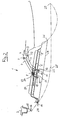
- Fig. 1 . 2 and 3 show the sliding door 1 according to an embodiment of the DE 10 2008 016 650 B3 ,
- the sliding door 1 is the left rear door of a motor vehicle. It is located in the opening of the body between the B-pillar 2 and a rear body part 3, in the region of a body flange 4 is connected to the body.
- the rear body part 3 may be the C pillar or the A pillar.
- the sliding door 1 has on its inside a guide rail 5.
- a slide 6 is mounted longitudinally displaceable.
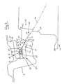
- the sliding door 1 further comprises a hinge bracket 7 and a control lever 11.
- the hinge bracket 7 is rotatably mounted on the sliding carriage 6 about a hinge 8 and on the body flange 4 about a hinge 9.
- the control lever 11 is rotatably mounted on the sliding carriage 6 about a hinge 12 and on the body flange 4 about a hinge 13.
- a first intermediate lever 10 is rotatably supported, about the axis of a hinge 17.
- a second intermediate lever 18 is rotatably supported, about the axis of a hinge 19.
- the hinge 19 is located in the outer region of the Sliding carriage 6. It lies in the region of the front end of the sliding carriage 6.
- the ends of the intermediate levers 10, 18 which are remote from the joints 17, 19 are connected to one another in a rotatable manner by a joint 20.
- the first intermediate lever 10 and the second intermediate lever 18 form a toggle. Since the connecting joint 20 of the intermediate levers 10, 18 with respect to the motor vehicle is located further inwardly than the joints 17, 19, the toggle formed by the intermediate levers 10, 18 with respect to the motor vehicle inward.
- a hinge plate 21 is fixed, which carries the joints 8, 12 and 19.
- the hinge bracket 7, the control lever 11, the slide 6 and the hinge plate 21 and the body flange 4 form with the joints 8, 9, 12 and 13 a multi-joint.
- a U-shaped receptacle 14 is provided on the sliding door 1, which is inclined to the vehicle longitudinal direction, namely in the vehicle direction forward inward. It is facing away from the hinge bracket 7, ie in the exemplary embodiment, the front inner end open.
- a hinge pin 16 is provided, which engages in the U-shaped receptacle 14. In the in Fig. 1 shown, fully closed position of the sliding door is the hinge pin 16 at the bottom of the U-shaped receptacle 14. He can be locked there (not shown in the drawing).
- the control lever 11 has an extension 22 which extends from the hinge 12 to the outside.
- the extension 22 extends the control lever 11 along the line connecting the hinge 13 to the hinge 12 beyond the hinge 12. In this case, the extension 22 bends slightly in relation to the connecting line between the joints 13 and 12, that is to say the longitudinal extension of the control lever 11, to the outside or rear.
- the hinge 17 is provided for the first intermediate lever 10 in the region of the outer end of the extension 22.
- a guide pin 23 is provided, which is guided in a guide track 24.
- the guideway 24 is provided on the sliding door 1. Accordingly, the guideway 24 is thus a door-resistant guideway. It is inclined relative to the guide rail 5 in the direction of the hinge bracket 7 away outwards.
- the guideway 24 is configured continuously linear. Their inclination is the same over their entire length.
- the hinge pin 16 is in the U-shaped receptacle 14, in the region of the end thereof.
- the guide pin 23 is located in the region of the rear, inner end of the guideway 24.
- the first intermediate lever 10 points from the Joint 17 forward and inward.
- the second intermediate lever 18 points from the hinge 19 backwards and inwards.
- a motor in particular an electric motor, for driving the guide rail 5 relative to the slide 6 may be present.
- a motor in particular an electric motor, for driving the hinge bracket 7 and / or the control lever 11 may be present. It is advantageous if a motor for driving the hinge bracket 7 and / or the control lever 11 is present on the body flange 4 or another body part.
- the opening movement can be generated instead or additionally by hand.
- the guide rail 5 can be moved manually to the rear relative to the sliding carriage 6.
- a handle or a plurality of handles can be provided on the sliding door 1, by which or the sliding door 1 and with it the guide rail 5 can be moved relative to the sliding carriage 6.
- the handle may be provided at the inner front end of the sliding door 1 and / or at the outer front end of the sliding door 1 and / or at the outer rear end of the sliding door 1.
- the sliding door 1 can be opened by a force attack on each of these three places and closed again.
- guide pin 23 prevents this free displacement and sets the relative position of the slide 6 relative to the guide rail 5 and thus against the sliding door 1 fixed. This takes place in the sections of the guideway 24, which have a non-zero inclination relative to the guide rail 5, which therefore do not run parallel to the guide rail 5.
- the guideway 24 has the same non-zero inclination relative to the guide rail 5 over its entire length.
- the drive movement for the opening of the sliding door 1 can also be initiated in other ways, in particular by a motor and / or manual drive of the hinge bracket 7 and / or the control lever 11 and / or the first intermediate lever 10 and / or the second intermediate lever 18 to one or more of the joints 9, 8, 13, 12, 17, 20, 19.
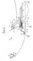
- the fully open position of the sliding door 1 is in Fig. 3 shown.
- the first intermediate lever 10 has been pivoted about the extension 17 about the hinge 17 by about 90 ° clockwise.
- the guide pin 23 has reached the front, closed end of the guideway 24.
- the second intermediate lever 18 has been pivoted about the hinge 19 by about 45 ° clockwise relative to the sliding carriage 6 and the hinge plate 21.
- the opening angle of the intermediate levers 10, 18 on the joint 20 has been increased from about 30 ° to about 150 °.
- the control lever 11 and the hinge bracket 7 were pivoted about the joints 13 and 9 at an angle of 120 ° counterclockwise.
- the closing movement of the sliding door 1 can be effected in that the guide rail 5 is moved by motor and / or manually relative to the sliding carriage 6 forward.
- the relative movement of the guide rail 5 is transmitted through the guide track 24 on the guide pin 23 and introduced from there via the first intermediate lever 10 in the multi-joint described.
- Fig. 1 . 2 and 3 the paths of the front end 25 and the rear end 26 of the outer door panel 27 are located.
- the front end 25 of the outer door panel 27 initially moves at an angle of about 30 ° relative to the vehicle longitudinal axis to the rear and outside.
- the inclination angle of the U-shaped receptacle 14 corresponds to this angle. It then describes an arc with a large radius, whose end 28 has a tangent parallel to the vehicle longitudinal axis.
- the rear end 26 of the outer door panel 27 initially moves approximately perpendicularly away from the body and then describes a narrowing arc to an end point 29 that is at substantially the same distance from the body of the vehicle as the end point 28 of the front end 25.
- Fig. 4 and 5 show the front part of a sliding door 41 according to the invention with a centering 42, unlike the embodiment according to Fig. 1 to 3 is trained.
- the centering 42 is attached to the rear end of the sliding door 41. It comprises a mounting flange 43 which is fixed to a front end plate 44 of the sliding door 41, and a centering surface 45th
- the centering surface 45 is located at the closed sliding door on a body-fixed counter surface 47.
- the body-mounted counter-surface 47 is provided on a body-side counter bearing 48 which is fixed to the B-pillar 2.
- the counter bearing 48 is designed cup-shaped. It is located in an opening in one of the Sliding door 41 facing sheet 61 of the B-pillar 2.
- the cup-shaped counter-bearing 48 is inserted into this opening. Outer edges 62 of the abutment 48 rest against the edges of the sheet 61 surrounding the opening.
- the counter-bearing 48 is located within the B-pillar 2.
- the centering surface 45 of the centering 42 has a portion 49 which extends inclined to the vehicle longitudinal direction.
- the section 49 is inclined in the vehicle direction forward and inward. He is just.
- the centering surface 45 further includes a portion 50 which is parallel to the vehicle longitudinal direction.
- the parallel portion 50 adjoins the inclined portion 49. It forms the end portion of the centering surface 45.
- the parallel portion 50 is in the vehicle longitudinal direction in front of the inclined portion 49. He has at its front end in the vehicle longitudinal direction a rounding 50 '.
- the body-mounted counter surface 47 is formed in a corresponding manner. It comprises a flat, inclined portion 51 and a subsequent parallel portion 52. In the closed state of the sliding door of the inclined portion 49 bears against the inclined portion 51, and the parallel portion 50 abuts the parallel portion 52 at. In this way, a reliable centering of the sliding door 41 is made possible in the closed position of the sliding door.
- a damper 63 is provided in the counter bearing 48.
- the damper 63 comprises a spring element 64, namely a compression spring, and a bolt 65 which is guided longitudinally displaceably in a guide 66.
- the guide 66 is located in the bottom of the pot-shaped counter-bearing 48. It runs in the longitudinal direction of the sliding door, which is identical to the longitudinal direction of the vehicle.
- the compression spring 64 is supported on the bottom of the pot-shaped counter-bearing 48 and on a collar 67 at the rear end of the bolt 65 from.
- By the compression spring 64 of the bolt 65 is biased in the rearward direction. Its path is limited by a collar 68 at the front end of the bolt 65, which on the outer surface of the bottom of the cup-shaped counter bearing 48 is present. In this position, the in Fig. 4 is shown, the compression spring 64 is biased.
- the outer, in the vehicle direction rear end surface of the collar 67 forms a stop surface 69 for the centering 42nd
- Fig. 4 shows the front part of the sliding door 41 in a partially open position before closing the sliding door 41.
- the rounding 50 'at the front end of the parallel portion 50 of the centering surface 45 of the centering 42 comes with the outer, rear end of the inclined portion 51 of the body-mounted counter surface 47 in Appendix and then slides the inclined portion 51 forward and in along.
- the front end surface 70 of the centering 42 comes into abutment with the abutment surface 69 of the bolt 65.
- the compression spring 64 dampens in this way the sliding door 41 when connecting the centering 42 with the anvil 48. The closing movement of the sliding door 41 is thus damped.
- the reverse path is gone through.
- the opening movement is supported by the compression spring 64.
- the centering 42 of the in Fig. 5 shown position to the rear and moved outside. Due to the parallel portion 50 of the centering surface 45 of the centering 42 and the associated parallel portion 52 of the body-fixed counter surface 47 of the body flange 48, the centering 42 initially moves only to the rear. Thereafter, when the length of the parallel portion 50 is overcome, an outward movement is superimposed by the inclined portions 49, 51. The centering 42 then moves evenly backwards and outwards.
- a fishing hook 46 is provided.
- the catch hook 46 is located at the front end of the centering 42. It lies opposite the parallel section 50 of the centering surface 45.
- the fishing hook 46 is directed inward in the vehicle longitudinal direction.
- the counterpart 53 is provided on the counter bearing 48. It lies in the vehicle longitudinal direction with the sliding door closed at the same height as the fishing hook 46 and within the fishing hook 46. If in a side impact, the sliding door 41 is deformed inward, the fishing hook 46 comes with the body-mounted counterpart 53 in abutment, creating an anchorage for the sliding door 41 is formed, which opposes a deformation of the sliding door 41 inwardly a resistance.
Abstract
Description
- Die Erfindung betrifft eine Schiebetüre für ein Fahrzeug, insbesondere für ein Kraftfahrzeug.
- Die Schiebetüre umfaßt eine Führungsschiene, einen Gleitschlitten und eine Zentrierung. Der Gleitschlitten ist an der Führungsschiene längsverschieblich gelagert und durch ein Mehrgelenk mit der Fahrzeugkarosserie verbunden. Die Zentrierung ist an dem dem Mehrgelenk abgewandten Ende der Schiebetüre vorgesehen. Sie ist mit einem karosserieseitigen Gegenlager lösbar verbindbar.
- Eine derartige Schiebetüre ist aus der
DE 10 2008 016 650 B3 , auf die hiermit ausdrücklich Bezug genommen wird, bekannt. Bei dieser Schiebetüre umfaßt das Mehrgelenk einen Scharnierbügel, der an dem Gleitschlitten und an einem Karosserieflansch drehbar gelagert ist, und einen Steuerhebel, der an dem Gleitschlitten und an einem oder dem Karosserieflansch drehbar gelagert ist. Die vorbekannte Schiebetüre umfaßt ferner einen ersten Zwischenhebel, der an dem Steuerhebel drehbar gelagert ist, und einen zweiten Zwischenhebel, der an dem ersten Zwischenhebel und an dem Gleitschlitten drehbar gelagert ist. Die Schiebetüre ist an dem dem Mehrgelenk abgewandten Ende durch eine Zentrierung drehbar und längsverschieblich gelagert. Sie ist dort arretierbar. Der Steuerhebel weist eine Verlängerung auf, an dem der erste Zwischenhebel drehbar gelagert ist. An dem Verbindungsgelenk des ersten Zwischenhebels und des zweiten Zwischenhebels ist ein Führungsstift vorgesehen, der in einer an der Schiebetüre vorgesehenen Führungsbahn geführt ist. Die Führungsbahn verläuft relativ zur Führungsschiene geneigt. Hierbei verläuft die Führungsbahn in Richtung von dem Scharnierbügel weg nach außen geneigt. - Eine andere Schiebetüre der eingangs angegebenen Art ist in der
EP 2 008 846 A2 beschrieben, auf die ebenfalls ausdrücklich Bezug genommen wird. Hier ist eine Antriebstange vorhanden, die an dem Steuerhebel drehbar gelagert ist. Die Schiebetüre ist an dem dem Mehrgelenk abgewandten Ende durch eine Zentrierung drehbar und längsverschieblich gelagert. Sie ist dort arretierbar. Die Antriebstange ist an der Führungsschiene drehbar gelagert. Der Steuerhebel weist einen Hebelarm auf, an dem die Antriebstange drehbar gelagert ist. An einem Zwischenhebel, der an dem Gleitschlitten drehbar gelagert ist, ist ein Führungsstift vorgesehen, der in einer an der Schiebetüre vorgesehenen Führungsbahn geführt ist. - Aus der prioritätsälteren, nicht vorveröffentlichten deutschen Patentanmeldung
10 2008 026 137.8 , die ebenfalls ausdrücklich in Bezug genommen wird, ist eine weitere Schiebetüre der eingangs angegebenen Art bekannt. Hier weist der Steuerhebel einen Hebelarm auf, an dem ein Führungsstift vorgesehen ist, der in einer an der Schiebetüre vorgesehenen Führungsbahn geführt ist. Die Führungsbahn verläuft vorzugsweise in Richtung von dem Scharnierbügel weg nach außen geneigt. - Aufgabe der Erfindung ist es, eine verbesserte Schiebetüre der eingangs angegebenen Art vorzuschlagen.
- Erfindungsgemäß wird diese Aufgabe durch die kennzeichnenden Merkmale des Anspruchs 1 gelöst. Die Schiebetüre umfaßt einen Dämpfer zum Dämpfen der Bewegung der Schiebetüre beim Verbinden der Zentrierung mit dem Gegenlager. Hierdurch kann die Bewegung der Schiebetüre bei deren Schließen gedämpft werden. Durch die Erfindung können Beschädigungen der Zentrierung und/oder des Gegenlagers beim Schließen der Schiebetüre vermieden werden. Ferner ist es möglich, den Bedienkomfort zu erhöhen.
- Vorteilhafte Weiterbildungen sind in den Unteransprüchen beschrieben.
- Der Dämpfer umfaßt vorzugsweise ein Federelement. Ein Dämpfer im Sinne der Erfindung kann also von einem Federelement gebildet werden. Ein geschwindigkeitsabhängiger Dämpfer ist hierfür nicht erforderlich. Es ist allerdings möglich, daß der erfindungsgemäße Dämpfer anstelle des Federelements oder zusätzlich zu diesem einen geschwindigkeitsabhängigen Dämpfer umfaßt.
- Das Federelement kann vorgespannt sein.
- Vorteilhaft ist es, wenn die Wirkrichtung des Dämpfers in Längsrichtung der Schiebetür verläuft. Dadurch kann die Dämpfungswirkung verbessert werden.
- Eine weitere vorteilhafte Weiterbildung ist dadurch gekennzeichnet, daß der Dämpfer einen Bolzen mit einer Anschlagfläche für die Zentrierung aufweist. Der Bolzen ist vorzugsweise längsverschieblich geführt. Vorteilhaft ist es, wenn der Bolzen in Längsrichtung der Schiebetür längsverschieblich gelagert ist.
- Vorzugsweise ist der Dämpfer in dem Gegenlager angeordnet. Es ist allerdings auch möglich, den Dämpfer in der Schiebetüre vorzusehen.
- Eine weitere vorteilhafte Weiterbildung ist dadurch gekennzeichnet, daß die Zentrierung eine Zentrierfläche aufweist, die bei geschlossener Schiebetüre an einer karosseriefesten Gegenfläche anliegt. Hierdurch wird eine zuverlässige Zentrierung der Schiebetüre in der geschlossenen Stellung ermöglicht.
- Die Zentrierfläche kann einen Abschnitt aufweisen, der geneigt zur Fahrzeug-Längsrichtung verläuft. Die karosseriefeste Gegenfläche ist vorzugsweise entsprechend ausgebildet. Der geneigt zur Fahrzeug-Längsrichtung verlaufende Abschnitt der Zentrierfläche ist vorzugsweise in Fahrzeugrichtung nach vorne und innen geneigt. Vorteilhaft ist es, wenn der geneigte Abschnitt der Zentrierfläche eben ist.
- Eine weitere vorteilhafte Weiterbildung ist dadurch gekennzeichnet, daß die Zentrierfläche einen Abschnitt aufweist, der parallel zur Fahrzeug-Längsrichtung verläuft. Die karosseriefeste Gegenfläche ist vorzugsweise entsprechend ausgebildet. Der parallel zur Fahrzeug-Längsrichtung verlaufende Abschnitt liegt vorzugsweise im Anschluß an einen Abschnitt, der geneigt zur Fahrzeug-Längsrichtung verläuft. Er bildet vorzugsweise einen Endabschnitt der Zentrierfläche.
- Die Erfindung betrifft ferner ein Fahrzeug, insbesondere ein Kraftfahrzeug, das durch eine oder mehrere erfindungsgemäße Schiebetüren gekennzeichnet ist.
- Ein Ausführungsbeispiel der Erfindung wird nachstehend anhand der beigefügten Zeichnung im einzelnen erläutert. In der Zeichnung zeigt
- Fig. 1
- eine vorbekannte Schiebetüre für ein Kraftfahrzeug in der geschlossenen Stellung in einer schematischen Ansicht von oben,
- Fig. 2
- die Schiebetüre gemäß
Fig. 1 in einer teilweise geöffneten Stellung in einer derFig. 1 entsprechenden schematischen Ansicht von oben, - Fig. 3
- die Schiebetüre gemäß
Fig. 1 und2 in der vollständig geöffneten Stellung in einer denFig. 1 und2 entsprechenden schematischen Ansicht von oben, - Fig. 4
- den vorderen Teil einer erfindungsgemäßen Schiebetüre der in
Fig. 1 bis 3 gezeigten Art in einer teilweise geöffneten Stellung in einer schematischen Ansicht von oben, - Fig. 5
- die Schiebetüre gemäß
Fig. 4 in der geschlossenen Stellung in einer derFig. 4 entsprechenden Ansicht von oben. -
Fig. 1 ,2 und3 zeigen die Schiebetüre 1 nach einem Ausführungsbeispiel derDE 10 2008 016 650 B3 . Die Schiebetüre 1 ist die linke hintere Türe eines Kraftfahrzeugs. Sie befindet sich in der Öffnung der Karosserie zwischen der B-Säule 2 und einem hinteren Karosserieteil 3, in dessen Bereich ein Karosserieflansch 4 mit der Karosserie verbunden ist. Bei dem hinteren Karosserieteil 3 kann es sich um die C-Säule oder um die A-Säule handeln. - Die Schiebetüre 1 weist an ihrer Innenseite eine Führungsschiene 5 auf. An der Führungsschiene 5 ist ein Gleitschlitten 6 längsverschieblich gelagert.
- Die Schiebetüre 1 weist ferner einen Scharnierbügel 7 und einen Steuerhebel 11 auf. Der Scharnierbügel 7 ist an dem Gleitschlitten 6 um ein Gelenk 8 und an dem Karosserieflansch 4 um ein Gelenk 9 drehbar gelagert. Der Steuerhebel 11 ist an dem Gleitschlitten 6 um ein Gelenk 12 und an dem Karosserieflansch 4 um ein Gelenk 13 drehbar gelagert.
- An dem Steuerhebel 11 ist ein erster Zwischenhebel 10 drehbar gelagert, und zwar um die Achse eines Gelenks 17. An dem Gleitschlitten 6 ist ein zweiter Zwischenhebel 18 drehbar gelagert, und zwar um die Achse eines Gelenks 19. Das Gelenk 19 liegt im äußeren Bereich des Gleitschlittens 6. Es liegt im Bereich des vorderen Endes des Gleitschlittens 6. Die von den Gelenken 17, 19 abgewandten Enden der Zwischenhebel 10, 18 sind durch ein Gelenk 20 drehbar miteinander verbunden. Der erste Zwischenhebel 10 und der zweite Zwischenhebel 18 bilden einen Kniehebel. Da das Verbindungsgelenk 20 der Zwischenhebel 10, 18 in Bezug auf das Kraftfahrzeug weiter innen liegt als die Gelenke 17, 19, weist der von den Zwischenhebeln 10, 18 gebildete Kniehebel in Bezug auf das Kraftfahrzeug nach innen.
- An dem Gleitschlitten 6 ist eine Gelenkplatte 21 befestigt, die die Gelenke 8, 12 und 19 trägt. Der Scharnierbügel 7, der Steuerhebel 11, der Gleitschlitten 6 bzw. die Gelenkplatte 21 und der Karosserieflansch 4 bilden mit den Gelenken 8, 9, 12 und 13 ein Mehrgelenk.
- An dem dem Scharnierbügel 7 gegenüberliegenden Ende der Schiebetüre 1 ist an der Schiebetüre 1 eine U-förmige Aufnahme 14 vorgesehen, die geneigt zur Fahrzeug-Längsrichtung verläuft, nämlich in Fahrzeugrichtung nach vorne nach innen. Sie ist an ihrem dem Scharnierbügel 7 abgewandten, im Ausführungsbeispiel also vorderen inneren Ende offen. An einem Karosserieflansch 15, der an der B-Säule 2 befestigt ist, ist ein Scharnierbolzen 16 vorgesehen, der in die U-förmige Aufnahme 14 eingreift. In der in
Fig. 1 gezeigten, vollständig geschlossenen Stellung der Schiebetüre befindet sich der Scharnierbolzen 16 am Grund der U-förmigen Aufnahme 14. Er kann dort arretiert werden (in der Zeichnung nicht dargestellt). - Der Steuerhebel 11 weist eine Verlängerung 22 auf, die sich von dem Gelenk 12 nach außen erstreckt. Die Verlängerung 22 verlängert den Steuerhebel 11 längs der Verbindungslinie von dem Gelenk 13 zu dem Gelenk 12 über das Gelenk 12 hinaus. Dabei knickt die Verlängerung 22 gegenüber der Verbindungslinie zwischen den Gelenken 13 und 12, also der Längserstreckung des Steuerhebels 11, geringfügig nach außen bzw. hinten ab. An dem Steuerhebel 11 ist im Bereich des äußeren Endes der Verlängerung 22 das Gelenk 17 für den ersten Zwischenhebel 10 vorgesehen.
- An dem Verbindungsgelenk 20 des ersten Zwischenhebels 10 und des zweiten Zwischenhebels 18 ist ein Führungsstift 23 vorgesehen, der in einer Führungsbahn 24 geführt ist. Die Führungsbahn 24 ist an der Schiebetüre 1 vorgesehen. Dementsprechend ist die Führungsbahn 24 also eine türfeste Führungsbahn. Sie verläuft relativ zur Führungsschiene 5 in Richtung von dem Scharnierbügel 7 weg nach außen geneigt. Die Führungsbahn 24 ist durchgehend linear ausgestaltet. Ihre Neigung ist über ihre gesamte Länge gleich groß.
- In der vollständig geschlossenen Stellung der Schiebetüre 1, die in
Fig. 1 gezeigt ist, liegt der Scharnierbolzen 16 in der U-förmigen Aufnahme 14, und zwar im Bereich von deren Ende. Der Führungsstift 23 befindet sich im Bereich des hinteren, inneren Endes der Führungsbahn 24. Der erste Zwischenhebel 10 weist von dem Gelenk 17 nach vorne und innen. Der zweite Zwischenhebel 18 weist von dem Gelenk 19 nach hinten und innen. - Im Verlauf der Öffnungsbewegung wird die Stellung nach
Fig. 2 durchlaufen. Diese Öffnungsbewegung kann dadurch erzeugt werden, daß die Führungsschiene 5 relativ zu dem Gleitschlitten 6 nach hinten bewegt wird. An dem Gleitschlitten 6 kann ein Motor, insbesondere ein Elektromotor, zum Antrieb der Führungsschiene 5 relativ zum Gleitschlitten 6 vorhanden sein. Stattdessen oder zusätzlich kann ein Motor, insbesondere ein Elektromotor, zum Antrieb des Scharnierbügels 7 und/oder des Steuerhebels 11 vorhanden sein. Vorteilhaft ist es, wenn an dem Karosserieflansch 4 oder einem sonstigen Karosserieteil ein Motor zum Antrieb des Scharnierbügels 7 und/oder des Steuerhebels 11 vorhanden ist. - Die Öffnungsbewegung kann allerdings stattdessen oder zusätzlich auch von Hand erzeugt werden. Insbesondere kann die Führungsschiene 5 manuell nach hinten relativ zum Gleitschlitten 6 bewegt werden. Zu diesem Zweck können an der Schiebetüre 1 ein Griff oder mehrere Griffe vorgesehen sein, durch den oder die die Schiebetüre 1 und mit ihr die Führungsschiene 5 relativ zum Gleitschlitten 6 bewegt werden kann. Der Griff kann am inneren vorderen Ende der Schiebetüre 1 und/oder am äußeren vorderen Ende der Schiebetüre 1 und/oder am äußeren hinteren Ende der Schiebetüre 1 vorgesehen sein. Die Schiebetüre 1 kann durch einen Kraftangriff an jeder dieser drei Stellen geöffnet und auch wieder geschlossen werden.
- Ohne den Führungsstift 23 könnte der Gleitschlitten 6 auf der Führungsschiene 5 frei verschoben werden. Der in der Führungsbahn 24 geführte Führungsstift 23 verhindert diese freie Verschiebbarkeit und legt die relative Position des Gleitschlittens 6 gegenüber der Führungsschiene 5 und damit gegenüber der Schiebetüre 1 fest. Dies erfolgt in den Abschnitten der Führungsbahn 24, die gegenüber der Führungsschiene 5 eine von Null verschiedene Neigung aufweisen, die also nicht parallel zur Führungsschiene 5 verlaufen. Die Führungsbahn 24 weist auf ihrer gesamten Länge dieselbe von Null verschiedene Neigung gegenüber der Führungsschiene 5 auf.
- Wenn die Führungsschiene 5 motorisch und/oder manuell relativ zum Gleitschlitten 6 nach hinten bewegt wird, bewegt sich der in der Führungsbahn 24 geführte Führungsstift 23 relativ zur Führungsschiene 5 und zum Gleitschlitten 6 nach außen, wodurch der zweite Zwischenhebel 18 im Uhrzeigersinn um das Gelenk 19 verschwenkt wird. Durch die Bewegung des Führungsstifts 23 relativ zum Gleitschlitten 6 nach hinten und außen wird das am anderen Ende des ersten Zwischenhebels 10 befindliche Gelenk 17 ebenfalls nach hinten bewegt, wodurch der Steuerhebel 11 entgegen dem Uhrzeigersinn um das Gelenk 12 gedreht wird. Hierdurch wird der Steuerhebel 11 entgegen dem Uhrzeigersinn um das Gelenk 13 an dem Karosserieflansch 4 verschwenkt. Durch die Verschwenkung des Steuerhebels 11 wird auch der Scharnierbügel 7 entgegen dem Uhrzeigersinn um das Gelenk 9 verschwenkt. Die Gelenkplatte 21 des Gleitschlittens 6 wird durch die Verschwenkung des Scharnierbügels 7 um das Gelenk 9 ebenfalls zwangsgeführt, da sie mit dem Scharnierbügel 7, dem Steuerhebel 11 und dem Karosserieflansch 4 - wie ausgeführt - ein Mehrgelenk bildet.
- Die Antriebsbewegung für die Öffnung der Schiebetüre 1 kann allerdings auch auf andere Weise eingeleitet werden, insbesondere durch einen motorischen und/oder manuellen Antrieb des Scharnierbügels 7 und/oder des Steuerhebels 11 und/oder des ersten Zwischenhebels 10 und/oder des zweiten Zwischenhebels 18 um eines oder mehrere der Gelenke 9, 8, 13, 12, 17, 20, 19.
- Die vollständig geöffnete Stellung der Schiebetüre 1 ist in
Fig. 3 dargestellt. Der erste Zwischenhebel 10 wurde gegenüber der Verlängerung 22 um das Gelenk 17 um etwa 90° im Uhrzeigersinn verschwenkt. Der Führungsstift 23 hat das vordere, geschlossene Ende der Führungsbahn 24 erreicht. Der zweite Zwischenhebel 18 wurde gegenüber dem Gleitschlitten 6 bzw. der Gelenkplatte 21 um das Gelenk 19 um etwa 45° im Uhrzeigersinn verschwenkt. Der Öffnungswinkel der Zwischenhebel 10, 18 an dem Gelenk 20 wurde von etwa 30° auf etwa 150° vergrößert. Der Steuerhebel 11 und der Scharnierbügel 7 wurden um einen Winkel von 120° entgegen dem Uhrzeigersinn um die Gelenke 13 und 9 verschwenkt. - Wenn die Schiebetüre 1 geschlossen werden soll, werden die beschriebenen Stellungen in umgekehrter Reihenfolge durchlaufen. Die Schließbewegung der Schiebetüre 1 kann dadurch bewirkt werden, daß die Führungsschiene 5 motorisch und/oder manuell relativ zum Gleitschlitten 6 nach vorne bewegt wird. Die Relativbewegung der Führungsschiene 5 wird durch die Führungsbahn 24 auf den Führungsstift 23 übertragen und von dort über den ersten Zwischenhebel 10 in das beschriebene Mehrgelenk eingeleitet. Es ist allerdings auch möglich, die Schließbewegung in einer Weise einzuleiten, wie sie für die Öffnungsbewegung beschrieben wurde.
- In
Fig. 1 ,2 und3 sind die Wege des vorderen Endes 25 und des hinteren Endes 26 des äußeren Türblechs 27 eingezeichnet. Das vordere Ende 25 des äußeren Türblechs 27 bewegt sich zunächst in einem Winkel von etwa 30° gegenüber der Fahrzeug-Längsachse nach hinten und außen. Der Neigungswinkel der U-förmigen Aufnahme 14 entspricht diesem Winkel. Es beschreibt anschließend einen Bogen mit einem großen Radius, dessen Ende 28 eine parallel zur Fahrzeug-Längsachse verlaufende Tangente aufweist. Das hintere Ende 26 des äußeren Türblechs 27 bewegt sich zunächst annähernd rechtwinkelig von der Karosserie weg und beschreibt dann einen enger werdenden Bogen bis zu einem Endpunkt 29, der im wesentlichen denselben Abstand von der Karosserie des Fahrzeugs aufweist wie der Endpunkt 28 des vorderen Endes 25. -
Fig. 4 und5 zeigen den vorderen Teil einer erfindungsgemäßen Schiebetüre 41 mit einer Zentrierung 42, die anders als bei der Ausführungsform nachFig. 1 bis 3 ausgebildet ist. Die Zentrierung 42 ist am hinteren Ende der Schiebetüre 41 befestigt. Sie umfaßt einen Befestigungsflansch 43, der an einem vorderen Abschlußblech 44 der Schiebetüre 41 befestigt ist, und eine Zentrierfläche 45. - Die Zentrierfläche 45 liegt bei geschlossener Schiebetüre an einer karosseriefesten Gegenfläche 47 an. Die karosseriefeste Gegenfläche 47 ist an einem karosserieseitigen Gegenlager 48 vorgesehen, das an der B-Säule 2 befestigt ist. Das Gegenlager 48 ist topfförmig ausgestaltet. Es befindet sich in einer Öffnung in einem der Schiebetüre 41 zugewandten Blech 61 der B-Säule 2. Das topfförmige Gegenlager 48 ist in diese Öffnung eingesetzt. Äußere Ränder 62 des Gegenlagers 48 liegen dabei an den die Öffnung umgebenden Rändern des Blechs 61 an. Das Gegenlager 48 befindet sich innerhalb der B-Säule 2.
- Die Zentrierfläche 45 der Zentrierung 42 weist einen Abschnitt 49 auf, der geneigt zur Fahrzeug-Längsrichtung verläuft. Der Abschnitt 49 ist in Fahrzeugrichtung nach vorne und innen geneigt. Er ist eben.
- Die Zentrierfläche 45 weist ferner einen Abschnitt 50 auf, der parallel zur Fahrzeug-Längsrichtung verläuft. Der parallele Abschnitt 50 schließt sich an den geneigten Abschnitt 49 an. Er bildet den Endabschnitt der Zentrierfläche 45. Der parallele Abschnitt 50 liegt in Fahrzeug-Längsrichtung vor dem geneigten Abschnitt 49. Er weist an seinem in Fahrzeug-Längsrichtung vorderen Ende eine Abrundung 50' auf.
- Die karosseriefeste Gegenfläche 47 ist in entsprechender Weise ausgebildet. Sie umfaßt einen ebenen, geneigten Abschnitt 51 und einen daran anschließenden parallelen Abschnitt 52. Im geschlossenen Zustand der Schiebetüre liegt der geneigte Abschnitt 49 an dem geneigten Abschnitt 51 an, und der parallele Abschnitt 50 liegt an dem parallelen Abschnitt 52 an. Auf diese Weise wird eine zuverlässige Zentrierung der Schiebetüre 41 in der geschlossenen Stellung der Schiebetüre ermöglicht.
- In dem Gegenlager 48 ist ein Dämpfer 63 vorgesehen. Der Dämpfer 63 umfaßt ein Federelement 64, nämlich eine Druckfeder, und einen Bolzen 65, der in einer Führung 66 längsverschieblich geführt ist. Die Führung 66 befindet sich im Boden des topfförmigen Gegenlagers 48. Sie verläuft in Längsrichtung der Schiebetür, die mit der Längsrichtung des Fahrzeugs identisch ist. Die Druckfeder 64 stützt sich am Boden des topfförmigen Gegenlagers 48 und an einem Bund 67 am hinteren Ende des Bolzens 65 ab. Durch die Druckfeder 64 wird der Bolzen 65 in Richtung nach hinten vorbelastet. Sein Weg wird durch einen Bund 68 am vorderen Ende des Bolzens 65 begrenzt, der an der Außenfläche des Bodens des topfförmigen Gegenlagers 48 anliegt. In dieser Stellung, die in
Fig. 4 gezeigt ist, ist die Druckfeder 64 vorgespannt. Die äußere, in Fahrzeugrichtung hintere Endfläche des Bundes 67 bildet eine Anschlagfläche 69 für die Zentrierung 42. -
Fig. 4 zeigt den vorderen Teil der Schiebetüre 41 in einer teilweise geöffneten Stellung vor dem Schließen der Schiebetüre 41. Die Abrundung 50' am vorderen Ende des parallelen Abschnitts 50 der Zentrierfläche 45 der Zentrierung 42 gelangt mit dem äußeren, hinteren Ende des geneigten Abschnitts 51 der karosseriefesten Gegenfläche 47 in Anlage und gleitet anschließend den geneigten Abschnitt 51 nach vorne und innen entlang. Bevor die Abrundung 50' am vorderen Ende des parallelen Abschnitts 50 das vordere innere Ende des geneigten Abschnitts 51 erreicht hat, gelangt die vordere Endfläche 70 der Zentrierung 42 mit der Anschlagfläche 69 des Bolzens 65 in Anlage. Während der weiteren Bewegung der Zentrierung 42 nach vorne wird der Bolzen 65 gegen die Kraft der Druckfeder 64 nach vorne gedrückt. Die Druckfeder 64 dämpft auf diese Weise die Schiebetür 41 beim Verbinden der Zentrierung 42 mit dem Gegenlager 48. Die Schließbewegung der Schiebetüre 41 wird also gedämpft. - Wenn die Abrundung 50' am vorderen Ende des parallelen Abschnitts 50 der Zentrierfläche 45 der Zentrierung 42 das vordere innere Ende des geneigten Abschnitts 51 der karosseriefesten Gegenfläche 47 des Karosserieflansches 48 erreicht hat, schließt sich eine ausschließliche Bewegung nach vorne an, die beendet ist, wenn der geneigte Abschnitt 49 vollständig an dem geneigten Abschnitt 51 anliegt, wie in
Fig. 5 gezeigt. In dieser Stellung ist die Schiebetüre 41 vollständig und zuverlässig verrastet. Auch während dieser ausschließlich nach vorne gerichteten Bewegung wird die Druckfeder 64 weiter zusammengedrückt. Mit zunehmender Schließung der Schiebetüre 41 wird die der Schließbewegung entgegengesetzte Kraft der Druckfeder 64 größer, so daß eine zunehmend bessere Dämpfungswirkung eintritt. - Beim Öffnen der Schiebetüre 41 wird der umgekehrte Weg durchlaufen. Die Öffnungsbewegung wird durch die Druckfeder 64 unterstützt. Bei der Öffnungsbewegung wird die Zentrierung 42 aus der in
Fig. 5 gezeigten Stellung nach hinten und außen bewegt. Aufgrund des parallelen Abschnitts 50 der Zentrierfläche 45 der Zentrierung 42 und des zugehörigen parallelen Abschnitts 52 der karosseriefesten Gegenfläche 47 des Karosserieflansches 48 bewegt sich die Zentrierung 42 zunächst ausschließlich nach hinten. Danach, wenn die Länge des parallelen Abschnitts 50 überwunden ist, wird durch die geneigten Abschnitte 49, 51 eine Bewegung nach außen überlagert. Die Zentrierung 42 bewegt sich dann gleichmäßig nach hinten und außen. Während dieser Bewegung gleitet die Abrundung 50' am vorderen Ende des parallelen Abschnitts 50 der Zentrierfläche 45 auf dem geneigten Abschnitt 51 der karosseriefesten Gegenfläche 47 nach hinten und außen. Das Ende dieser Gleitbewegung ist inFig. 5 dargestellt, in der sich die Abrundung 50' am vorderen Ende des parallelen Abschnitts 50 am hinteren, äußeren Ende des geneigten Abschnitts 51 befindet. Danach hebt die Zentrierung 42 von der karosseriefesten Gegenfläche 47 ab. Die Abrundung 50' folgt der Verlaufskurve 71. - An der Zentrierung 42 ist ein Fanghaken 46 vorgesehen. Der Fanghaken 46 befindet sich am vorderen Ende der Zentrierung 42. Er liegt dem parallelen Abschnitt 50 der Zentrierfläche 45 gegenüber. Der Fanghaken 46 ist in Fahrzeug-Längsrichtung nach innen gerichtet. Bei geschlossener Schiebetüre liegt ihm ein karosseriefestes Gegenstück 53 gegenüber. Das Gegenstück 53 ist an dem Gegenlager 48 vorgesehen. Es liegt in Fahrzeug-Längsrichtung bei geschlossener Schiebetüre auf gleicher Höhe wie der Fanghaken 46 und innerhalb des Fanghakens 46. Wenn bei einem Seitenaufprall die Schiebetüre 41 nach innen verformt wird, gelangt der Fanghaken 46 mit dem karosseriefesten Gegenstück 53 in Anlage, wodurch eine Verankerung für die Schiebetüre 41 gebildet wird, die einer Verformung der Schiebetüre 41 nach innen einen Widerstand entgegensetzt.
Claims (10)
- Schiebetüre für ein Fahrzeug mit einer Führungsschiene (5), mit einem Gleitschlitten (6), der an der Führungsschiene (5) längsverschieblich gelagert ist und der durch ein Mehrgelenk (7, 11, 6, 4) mit der Fahrzeugkarosserie verbunden ist, und mit einer Zentrierung (42) an ihrem dem Mehrgelenk (7, 11, 6, 4) abgewandten Ende, die mit einem karosserieseitigen Gegenlager (48) lösbar verbindbar ist,
gekennzeichnet durch
einen Dämpfer (63) zum Dämpfen der Bewegung der Schiebetür (41) beim Verbinden der Zentrierung (42) mit dem Gegenlager (48). - Schiebetüre nach Anspruch 1, dadurch gekennzeichnet, daß der Dämpfer (63) ein Federelement (64) umfaßt.
- Schiebetüre nach Anspruch 2, dadurch gekennzeichnet, daß das Federelement (64) vorgespannt ist.
- Schiebetüre nach einem der vorhergehenden Ansprüche, dadurch gekennzeichnet, daß die Wirkrichtung des Dämpfers (63) in Längsrichtung der Schiebetür (41) verläuft.
- Schiebetüre nach einem der vorhergehenden Ansprüche, dadurch gekennzeichnet, daß der Dämpfer (63) einen Bolzen (65) mit einer Anschlagfläche (69) für die Zentrierung (42) aufweist.
- Schiebetüre nach einem der vorhergehenden Ansprüche, dadurch gekennzeichnet, daß der Dämpfer (63) in dem Gegenlager (48) angeordnet ist.
- Schiebetüre nach einem der vorhergehenden Ansprüche, dadurch gekennzeichnet, daß die Zentrierung (42) eine Zentrierfläche (45) aufweist, die bei geschlossener Schiebetüre an einer karosseriefesten Gegenfläche anliegt.
- Schiebetüre nach Anspruch 7, dadurch gekennzeichnet, daß die Zentrierfläche (45) einen Abschnitt (49) aufweist, der geneigt zur Fahrzeug-Längsrichtung verläuft.
- Schiebetüre nach Anspruch 7 oder 8, dadurch gekennzeichnet, daß die Zentrierfläche (45) einen Abschnitt (50) aufweist, der parallel zur Fahrzeug-Längsrichtung verläuft.
- Fahrzeug, insbesondere Kraftfahrzeug, gekennzeichnet durch eine oder mehrere Schiebetüren nach einem der Ansprüche 1 bis 9.
Applications Claiming Priority (1)
| Application Number | Priority Date | Filing Date | Title |
|---|---|---|---|
| DE102009057325A DE102009057325A1 (de) | 2009-12-07 | 2009-12-07 | Schiebetüre für ein Fahrzeug |
Publications (2)
| Publication Number | Publication Date |
|---|---|
| EP2329976A1 true EP2329976A1 (de) | 2011-06-08 |
| EP2329976B1 EP2329976B1 (de) | 2012-10-24 |
Family
ID=43569324
Family Applications (1)
| Application Number | Title | Priority Date | Filing Date |
|---|---|---|---|
| EP10014507A Not-in-force EP2329976B1 (de) | 2009-12-07 | 2010-11-11 | Schiebetüre für ein Fahrzeug |
Country Status (6)
| Country | Link |
|---|---|
| US (1) | US20110131883A1 (de) |
| EP (1) | EP2329976B1 (de) |
| CN (1) | CN102085791B (de) |
| BR (1) | BRPI1005071A2 (de) |
| DE (1) | DE102009057325A1 (de) |
| MX (1) | MX2010012693A (de) |
Cited By (2)
| Publication number | Priority date | Publication date | Assignee | Title |
|---|---|---|---|---|
| DE102011082526A1 (de) | 2011-09-12 | 2013-03-14 | Ford Global Technologies, Llc | Fahrzeug mit Schiebetürsystem |
| FR2996171A1 (fr) * | 2012-10-02 | 2014-04-04 | Peugeot Citroen Automobiles Sa | Dispositif pour centrer et retenir une porte laterale coulissante d’un vehicule automobile, en cas de choc |
Families Citing this family (4)
| Publication number | Priority date | Publication date | Assignee | Title |
|---|---|---|---|---|
| KR101491240B1 (ko) * | 2013-03-15 | 2015-02-11 | 현대자동차주식회사 | 인비저블 슬라이딩 도어 링크 구조 |
| GB2528131A (en) * | 2014-07-11 | 2016-01-13 | Airbus Uk Ltd | Door abutment |
| CN106801564B (zh) * | 2017-03-13 | 2019-06-25 | 珠海广式得建材有限公司 | 一种高安装性隐藏门 |
| KR20180126184A (ko) * | 2017-05-17 | 2018-11-27 | 현대자동차주식회사 | 슬라이딩 도어의 비접촉식 전력 전달 구조 |
Citations (5)
| Publication number | Priority date | Publication date | Assignee | Title |
|---|---|---|---|---|
| JPS60110525A (ja) * | 1983-11-21 | 1985-06-17 | Mitsubishi Motors Corp | 車両用強化ドア装置 |
| US6206455B1 (en) * | 1999-04-30 | 2001-03-27 | Daimlerchrysler Corporation | Sliding door stabilizer |
| EP2008846A2 (de) | 2007-06-28 | 2008-12-31 | DURA Automotive Body and Glass Systems GmbH | Schiebetüre für ein Fahrzeug |
| DE102008016650B3 (de) | 2008-04-01 | 2009-05-14 | Dura Automotive Body & Glass Systems Gmbh | Schiebetüre für ein Fahrzeug |
| FR2924150A1 (fr) * | 2007-11-26 | 2009-05-29 | Peugeot Citroen Automobiles Sa | Dispositif de centrage d'une porte coulissante et vehicule automobile comportant un tel dispositif de centrage |
Family Cites Families (13)
| Publication number | Priority date | Publication date | Assignee | Title |
|---|---|---|---|---|
| US2024885A (en) * | 1932-07-25 | 1935-12-17 | Rudolph I Schonitzer | Vehicle door support |
| US2998275A (en) * | 1956-09-24 | 1961-08-29 | Daimler Benz Ag | Door lock for motor vehicles |
| US4159837A (en) * | 1978-07-27 | 1979-07-03 | Morita Hardware Manufacturing, Inc. | Combination door stop and latching device |
| US4302864A (en) * | 1979-11-16 | 1981-12-01 | Morita Mike Y | Combination door stop and latching device |
| GB2164090B (en) * | 1984-07-26 | 1987-10-14 | Ohi Seisakusho Co Ltd | Automatic sliding door system for vehicles |
| US5791723A (en) * | 1997-01-16 | 1998-08-11 | Ford Motor Company | Bumper wedge for automotive vehicle sliding door |
| KR100320835B1 (ko) * | 1999-12-29 | 2002-01-18 | 이계안 | 자동차용 테일 게이트 진동 방지 구조 |
| US7017229B2 (en) * | 2003-01-14 | 2006-03-28 | Richard Walcome | Latching door stop for a marine vessel |
| US7393044B2 (en) * | 2005-05-31 | 2008-07-01 | Mitsuba Corporation | Vehicle door opening and closing structure |
| HU3176U (en) * | 2006-03-10 | 2006-10-30 | Jozsef Bereznai | Universal impact-hinder apparatus |
| KR100872183B1 (ko) * | 2006-11-30 | 2008-12-09 | 볼보 컨스트럭션 이키프먼트 홀딩 스웨덴 에이비 | 중장비용 운전실 |
| JP5056389B2 (ja) * | 2007-12-12 | 2012-10-24 | スズキ株式会社 | 車両用スライドドアの拘束構造 |
| DE102008026137B4 (de) | 2008-05-30 | 2013-01-03 | Dura Automotive Body & Glass Systems Gmbh | Schiebetüre für ein Fahrzeug |
-
2009
- 2009-12-07 DE DE102009057325A patent/DE102009057325A1/de not_active Withdrawn
-
2010
- 2010-11-11 EP EP10014507A patent/EP2329976B1/de not_active Not-in-force
- 2010-11-19 MX MX2010012693A patent/MX2010012693A/es active IP Right Grant
- 2010-12-06 US US12/960,695 patent/US20110131883A1/en not_active Abandoned
- 2010-12-07 CN CN201010585791.0A patent/CN102085791B/zh not_active Expired - Fee Related
- 2010-12-07 BR BRPI1005071-0A patent/BRPI1005071A2/pt not_active IP Right Cessation
Patent Citations (5)
| Publication number | Priority date | Publication date | Assignee | Title |
|---|---|---|---|---|
| JPS60110525A (ja) * | 1983-11-21 | 1985-06-17 | Mitsubishi Motors Corp | 車両用強化ドア装置 |
| US6206455B1 (en) * | 1999-04-30 | 2001-03-27 | Daimlerchrysler Corporation | Sliding door stabilizer |
| EP2008846A2 (de) | 2007-06-28 | 2008-12-31 | DURA Automotive Body and Glass Systems GmbH | Schiebetüre für ein Fahrzeug |
| FR2924150A1 (fr) * | 2007-11-26 | 2009-05-29 | Peugeot Citroen Automobiles Sa | Dispositif de centrage d'une porte coulissante et vehicule automobile comportant un tel dispositif de centrage |
| DE102008016650B3 (de) | 2008-04-01 | 2009-05-14 | Dura Automotive Body & Glass Systems Gmbh | Schiebetüre für ein Fahrzeug |
Cited By (7)
| Publication number | Priority date | Publication date | Assignee | Title |
|---|---|---|---|---|
| DE102011082526A1 (de) | 2011-09-12 | 2013-03-14 | Ford Global Technologies, Llc | Fahrzeug mit Schiebetürsystem |
| WO2013037587A1 (de) | 2011-09-12 | 2013-03-21 | Ford Global Technologies, Llc | Fahrzeug mit schiebetürsystem |
| CN103781646A (zh) * | 2011-09-12 | 2014-05-07 | 福特全球技术公司 | 具有滑动车门系统的车辆 |
| US9254731B2 (en) | 2011-09-12 | 2016-02-09 | Ford Global Technologies, Llc | Vehicle with a sliding door system |
| CN103781646B (zh) * | 2011-09-12 | 2016-07-06 | 福特全球技术公司 | 具有滑动车门系统的车辆 |
| US9821639B2 (en) | 2011-09-12 | 2017-11-21 | Ford Global Technologies, Llc | Vehicle with a sliding door system |
| FR2996171A1 (fr) * | 2012-10-02 | 2014-04-04 | Peugeot Citroen Automobiles Sa | Dispositif pour centrer et retenir une porte laterale coulissante d’un vehicule automobile, en cas de choc |
Also Published As
| Publication number | Publication date |
|---|---|
| US20110131883A1 (en) | 2011-06-09 |
| CN102085791A (zh) | 2011-06-08 |
| BRPI1005071A2 (pt) | 2013-03-26 |
| DE102009057325A1 (de) | 2011-06-09 |
| MX2010012693A (es) | 2011-06-24 |
| CN102085791B (zh) | 2015-07-29 |
| EP2329976B1 (de) | 2012-10-24 |
Similar Documents
| Publication | Publication Date | Title |
|---|---|---|
| EP2008846B1 (de) | Schiebetüre für ein Fahrzeug | |
| EP2257443B1 (de) | Schiebetüre für ein fahrzeug | |
| EP1721768B1 (de) | Schiebetüre für ein Kraftfahrzeug | |
| EP2127928B1 (de) | Schiebetür für ein Fahrzeug | |
| EP2329976B1 (de) | Schiebetüre für ein Fahrzeug | |
| EP2332759B1 (de) | Fahrzeug mit einer Schiebetüre | |
| EP2329975B1 (de) | Schiebetüre für ein Fahrzeug | |
| EP2338715B1 (de) | Schiebetüre für ein Fahrzeug | |
| WO2017108022A1 (de) | Sicherheitsvorrichtung für ein kraftfahrzeug mit einer drehfalle und einer auswurffeder | |
| DE102011085177B4 (de) | Antriebssystem für ein KFZ-Dachsystem | |
| DE10025925B4 (de) | Seitentür eines Kraftfahrzeugs | |
| EP2332659A2 (de) | Montagevorrichtung zum Montieren einer Rohbau-Schiebetüre eines Kraftfahrzeugs | |
| DE102007024572A1 (de) | Scharnier für eine Kraftfahrzeugtür | |
| DE102004010136B3 (de) | Vorrichtung zur Betätigung eines kombinierten Heck- und Verdeckdeckels für ein Cabriolet-Fahrzeug | |
| DE102007035230A1 (de) | Schiebetüre für ein Fahrzeug | |
| DE10117769B4 (de) | Vorrichtung zur Unterstützung einer Öffnungsbewegung einer Fahrzeugklappe | |
| EP1380718B1 (de) | Vorrichtung zur automatischen Betätigung einer Kraftfahrzeugschiebetür | |
| DE102004035093B4 (de) | Verdeck für ein Cabriolet-Fahrzeug | |
| EP2335957B1 (de) | Schiebetüre für ein Fahrzeug | |
| DE102007053994A1 (de) | Scharnier mit Arretiervorrichtung für Kraftfahrzeugklappe | |
| WO2009000548A2 (de) | Schiebetüre für ein fahrzeug | |
| DE102007006262A1 (de) | Anordnung eines Außenspiegels an einem Kraftwagen | |
| DE102005019942A1 (de) | Vorrichtung zur Bewegung eines Heckdeckels |
Legal Events
| Date | Code | Title | Description |
|---|---|---|---|
| PUAI | Public reference made under article 153(3) epc to a published international application that has entered the european phase |
Free format text: ORIGINAL CODE: 0009012 |
|
| AK | Designated contracting states |
Kind code of ref document: A1 Designated state(s): AL AT BE BG CH CY CZ DE DK EE ES FI FR GB GR HR HU IE IS IT LI LT LU LV MC MK MT NL NO PL PT RO RS SE SI SK SM TR |
|
| AX | Request for extension of the european patent |
Extension state: BA ME |
|
| 17P | Request for examination filed |
Effective date: 20111205 |
|
| GRAP | Despatch of communication of intention to grant a patent |
Free format text: ORIGINAL CODE: EPIDOSNIGR1 |
|
| GRAS | Grant fee paid |
Free format text: ORIGINAL CODE: EPIDOSNIGR3 |
|
| GRAA | (expected) grant |
Free format text: ORIGINAL CODE: 0009210 |
|
| AK | Designated contracting states |
Kind code of ref document: B1 Designated state(s): AL AT BE BG CH CY CZ DE DK EE ES FI FR GB GR HR HU IE IS IT LI LT LU LV MC MK MT NL NO PL PT RO RS SE SI SK SM TR |
|
| REG | Reference to a national code |
Ref country code: GB Ref legal event code: FG4D Free format text: NOT ENGLISH |
|
| REG | Reference to a national code |
Ref country code: CH Ref legal event code: EP |
|
| REG | Reference to a national code |
Ref country code: AT Ref legal event code: REF Ref document number: 580719 Country of ref document: AT Kind code of ref document: T Effective date: 20121115 |
|
| REG | Reference to a national code |
Ref country code: IE Ref legal event code: FG4D Free format text: LANGUAGE OF EP DOCUMENT: GERMAN |
|
| REG | Reference to a national code |
Ref country code: DE Ref legal event code: R096 Ref document number: 502010001478 Country of ref document: DE Effective date: 20121220 |
|
| REG | Reference to a national code |
Ref country code: NL Ref legal event code: VDEP Effective date: 20121024 |
|
| PG25 | Lapsed in a contracting state [announced via postgrant information from national office to epo] |
Ref country code: NL Free format text: LAPSE BECAUSE OF FAILURE TO SUBMIT A TRANSLATION OF THE DESCRIPTION OR TO PAY THE FEE WITHIN THE PRESCRIBED TIME-LIMIT Effective date: 20121024 Ref country code: SE Free format text: LAPSE BECAUSE OF FAILURE TO SUBMIT A TRANSLATION OF THE DESCRIPTION OR TO PAY THE FEE WITHIN THE PRESCRIBED TIME-LIMIT Effective date: 20121024 Ref country code: ES Free format text: LAPSE BECAUSE OF FAILURE TO SUBMIT A TRANSLATION OF THE DESCRIPTION OR TO PAY THE FEE WITHIN THE PRESCRIBED TIME-LIMIT Effective date: 20130204 Ref country code: FI Free format text: LAPSE BECAUSE OF FAILURE TO SUBMIT A TRANSLATION OF THE DESCRIPTION OR TO PAY THE FEE WITHIN THE PRESCRIBED TIME-LIMIT Effective date: 20121024 Ref country code: HR Free format text: LAPSE BECAUSE OF FAILURE TO SUBMIT A TRANSLATION OF THE DESCRIPTION OR TO PAY THE FEE WITHIN THE PRESCRIBED TIME-LIMIT Effective date: 20121024 Ref country code: NO Free format text: LAPSE BECAUSE OF FAILURE TO SUBMIT A TRANSLATION OF THE DESCRIPTION OR TO PAY THE FEE WITHIN THE PRESCRIBED TIME-LIMIT Effective date: 20130124 Ref country code: IS Free format text: LAPSE BECAUSE OF FAILURE TO SUBMIT A TRANSLATION OF THE DESCRIPTION OR TO PAY THE FEE WITHIN THE PRESCRIBED TIME-LIMIT Effective date: 20130224 |
|
| BERE | Be: lapsed |
Owner name: DURA AUTOMOTIVE BODY AND GLASS SYSTEMS G.M.B.H. Effective date: 20121130 |
|
| PG25 | Lapsed in a contracting state [announced via postgrant information from national office to epo] |
Ref country code: PT Free format text: LAPSE BECAUSE OF FAILURE TO SUBMIT A TRANSLATION OF THE DESCRIPTION OR TO PAY THE FEE WITHIN THE PRESCRIBED TIME-LIMIT Effective date: 20130225 Ref country code: SI Free format text: LAPSE BECAUSE OF FAILURE TO SUBMIT A TRANSLATION OF THE DESCRIPTION OR TO PAY THE FEE WITHIN THE PRESCRIBED TIME-LIMIT Effective date: 20121024 Ref country code: LV Free format text: LAPSE BECAUSE OF FAILURE TO SUBMIT A TRANSLATION OF THE DESCRIPTION OR TO PAY THE FEE WITHIN THE PRESCRIBED TIME-LIMIT Effective date: 20121024 Ref country code: PL Free format text: LAPSE BECAUSE OF FAILURE TO SUBMIT A TRANSLATION OF THE DESCRIPTION OR TO PAY THE FEE WITHIN THE PRESCRIBED TIME-LIMIT Effective date: 20121024 Ref country code: GR Free format text: LAPSE BECAUSE OF FAILURE TO SUBMIT A TRANSLATION OF THE DESCRIPTION OR TO PAY THE FEE WITHIN THE PRESCRIBED TIME-LIMIT Effective date: 20130125 |
|
| PG25 | Lapsed in a contracting state [announced via postgrant information from national office to epo] |
Ref country code: EE Free format text: LAPSE BECAUSE OF FAILURE TO SUBMIT A TRANSLATION OF THE DESCRIPTION OR TO PAY THE FEE WITHIN THE PRESCRIBED TIME-LIMIT Effective date: 20121024 Ref country code: DK Free format text: LAPSE BECAUSE OF FAILURE TO SUBMIT A TRANSLATION OF THE DESCRIPTION OR TO PAY THE FEE WITHIN THE PRESCRIBED TIME-LIMIT Effective date: 20121024 Ref country code: BG Free format text: LAPSE BECAUSE OF FAILURE TO SUBMIT A TRANSLATION OF THE DESCRIPTION OR TO PAY THE FEE WITHIN THE PRESCRIBED TIME-LIMIT Effective date: 20130124 Ref country code: SK Free format text: LAPSE BECAUSE OF FAILURE TO SUBMIT A TRANSLATION OF THE DESCRIPTION OR TO PAY THE FEE WITHIN THE PRESCRIBED TIME-LIMIT Effective date: 20121024 Ref country code: RS Free format text: LAPSE BECAUSE OF FAILURE TO SUBMIT A TRANSLATION OF THE DESCRIPTION OR TO PAY THE FEE WITHIN THE PRESCRIBED TIME-LIMIT Effective date: 20121024 Ref country code: CZ Free format text: LAPSE BECAUSE OF FAILURE TO SUBMIT A TRANSLATION OF THE DESCRIPTION OR TO PAY THE FEE WITHIN THE PRESCRIBED TIME-LIMIT Effective date: 20121024 |
|
| REG | Reference to a national code |
Ref country code: IE Ref legal event code: MM4A |
|
| PG25 | Lapsed in a contracting state [announced via postgrant information from national office to epo] |
Ref country code: RO Free format text: LAPSE BECAUSE OF FAILURE TO SUBMIT A TRANSLATION OF THE DESCRIPTION OR TO PAY THE FEE WITHIN THE PRESCRIBED TIME-LIMIT Effective date: 20121024 Ref country code: IT Free format text: LAPSE BECAUSE OF FAILURE TO SUBMIT A TRANSLATION OF THE DESCRIPTION OR TO PAY THE FEE WITHIN THE PRESCRIBED TIME-LIMIT Effective date: 20121024 Ref country code: BE Free format text: LAPSE BECAUSE OF NON-PAYMENT OF DUE FEES Effective date: 20121130 |
|
| PLBE | No opposition filed within time limit |
Free format text: ORIGINAL CODE: 0009261 |
|
| STAA | Information on the status of an ep patent application or granted ep patent |
Free format text: STATUS: NO OPPOSITION FILED WITHIN TIME LIMIT |
|
| 26N | No opposition filed |
Effective date: 20130725 |
|
| PG25 | Lapsed in a contracting state [announced via postgrant information from national office to epo] |
Ref country code: IE Free format text: LAPSE BECAUSE OF NON-PAYMENT OF DUE FEES Effective date: 20121111 |
|
| REG | Reference to a national code |
Ref country code: DE Ref legal event code: R097 Ref document number: 502010001478 Country of ref document: DE Effective date: 20130725 |
|
| PG25 | Lapsed in a contracting state [announced via postgrant information from national office to epo] |
Ref country code: MT Free format text: LAPSE BECAUSE OF FAILURE TO SUBMIT A TRANSLATION OF THE DESCRIPTION OR TO PAY THE FEE WITHIN THE PRESCRIBED TIME-LIMIT Effective date: 20121024 Ref country code: CY Free format text: LAPSE BECAUSE OF FAILURE TO SUBMIT A TRANSLATION OF THE DESCRIPTION OR TO PAY THE FEE WITHIN THE PRESCRIBED TIME-LIMIT Effective date: 20121024 Ref country code: AL Free format text: LAPSE BECAUSE OF FAILURE TO SUBMIT A TRANSLATION OF THE DESCRIPTION OR TO PAY THE FEE WITHIN THE PRESCRIBED TIME-LIMIT Effective date: 20121024 |
|
| PG25 | Lapsed in a contracting state [announced via postgrant information from national office to epo] |
Ref country code: MC Free format text: LAPSE BECAUSE OF NON-PAYMENT OF DUE FEES Effective date: 20121130 Ref country code: TR Free format text: LAPSE BECAUSE OF FAILURE TO SUBMIT A TRANSLATION OF THE DESCRIPTION OR TO PAY THE FEE WITHIN THE PRESCRIBED TIME-LIMIT Effective date: 20121024 |
|
| PG25 | Lapsed in a contracting state [announced via postgrant information from national office to epo] |
Ref country code: SM Free format text: LAPSE BECAUSE OF FAILURE TO SUBMIT A TRANSLATION OF THE DESCRIPTION OR TO PAY THE FEE WITHIN THE PRESCRIBED TIME-LIMIT Effective date: 20121024 Ref country code: LU Free format text: LAPSE BECAUSE OF NON-PAYMENT OF DUE FEES Effective date: 20121111 |
|
| PG25 | Lapsed in a contracting state [announced via postgrant information from national office to epo] |
Ref country code: HU Free format text: LAPSE BECAUSE OF FAILURE TO SUBMIT A TRANSLATION OF THE DESCRIPTION OR TO PAY THE FEE WITHIN THE PRESCRIBED TIME-LIMIT Effective date: 20101111 Ref country code: LT Free format text: LAPSE BECAUSE OF FAILURE TO SUBMIT A TRANSLATION OF THE DESCRIPTION OR TO PAY THE FEE WITHIN THE PRESCRIBED TIME-LIMIT Effective date: 20121024 |
|
| REG | Reference to a national code |
Ref country code: CH Ref legal event code: PL |
|
| PG25 | Lapsed in a contracting state [announced via postgrant information from national office to epo] |
Ref country code: CH Free format text: LAPSE BECAUSE OF NON-PAYMENT OF DUE FEES Effective date: 20141130 Ref country code: MK Free format text: LAPSE BECAUSE OF FAILURE TO SUBMIT A TRANSLATION OF THE DESCRIPTION OR TO PAY THE FEE WITHIN THE PRESCRIBED TIME-LIMIT Effective date: 20121024 Ref country code: LI Free format text: LAPSE BECAUSE OF NON-PAYMENT OF DUE FEES Effective date: 20141130 |
|
| REG | Reference to a national code |
Ref country code: FR Ref legal event code: PLFP Year of fee payment: 6 |
|
| REG | Reference to a national code |
Ref country code: FR Ref legal event code: PLFP Year of fee payment: 7 |
|
| REG | Reference to a national code |
Ref country code: AT Ref legal event code: MM01 Ref document number: 580719 Country of ref document: AT Kind code of ref document: T Effective date: 20151111 |
|
| REG | Reference to a national code |
Ref country code: DE Ref legal event code: R082 Ref document number: 502010001478 Country of ref document: DE Representative=s name: LORENZ SEIDLER GOSSEL RECHTSANWAELTE PATENTANW, DE Ref country code: DE Ref legal event code: R081 Ref document number: 502010001478 Country of ref document: DE Owner name: DURA AUTOMOTIVE HOLDINGS U.K., LTD., CASTLE VA, GB Free format text: FORMER OWNER: DURA AUTOMOTIVE BODY AND GLASS SYSTEMS GMBH, 58840 PLETTENBERG, DE |
|
| PG25 | Lapsed in a contracting state [announced via postgrant information from national office to epo] |
Ref country code: AT Free format text: LAPSE BECAUSE OF NON-PAYMENT OF DUE FEES Effective date: 20151111 |
|
| REG | Reference to a national code |
Ref country code: FR Ref legal event code: TP Owner name: DURA AUTOMOTIVE BODY AND GLASS SYSTEMS GMBH, DE Effective date: 20170629 |
|
| REG | Reference to a national code |
Ref country code: GB Ref legal event code: 732E Free format text: REGISTERED BETWEEN 20170727 AND 20170802 |
|
| REG | Reference to a national code |
Ref country code: FR Ref legal event code: PLFP Year of fee payment: 8 |
|
| PGFP | Annual fee paid to national office [announced via postgrant information from national office to epo] |
Ref country code: DE Payment date: 20200327 Year of fee payment: 10 Ref country code: GB Payment date: 20200327 Year of fee payment: 10 |
|
| PGFP | Annual fee paid to national office [announced via postgrant information from national office to epo] |
Ref country code: FR Payment date: 20200325 Year of fee payment: 10 |
|
| REG | Reference to a national code |
Ref country code: DE Ref legal event code: R119 Ref document number: 502010001478 Country of ref document: DE |
|
| GBPC | Gb: european patent ceased through non-payment of renewal fee |
Effective date: 20201111 |
|
| PG25 | Lapsed in a contracting state [announced via postgrant information from national office to epo] |
Ref country code: FR Free format text: LAPSE BECAUSE OF NON-PAYMENT OF DUE FEES Effective date: 20201130 |
|
| PG25 | Lapsed in a contracting state [announced via postgrant information from national office to epo] |
Ref country code: GB Free format text: LAPSE BECAUSE OF NON-PAYMENT OF DUE FEES Effective date: 20201111 Ref country code: DE Free format text: LAPSE BECAUSE OF NON-PAYMENT OF DUE FEES Effective date: 20210601 |