EP2329877A1 - Elément micro-fluidique destiné à l'analyse d'un échantillon de liquide - Google Patents
Elément micro-fluidique destiné à l'analyse d'un échantillon de liquide Download PDFInfo
- Publication number
- EP2329877A1 EP2329877A1 EP09015031A EP09015031A EP2329877A1 EP 2329877 A1 EP2329877 A1 EP 2329877A1 EP 09015031 A EP09015031 A EP 09015031A EP 09015031 A EP09015031 A EP 09015031A EP 2329877 A1 EP2329877 A1 EP 2329877A1
- Authority
- EP
- European Patent Office
- Prior art keywords
- reagent
- reagent chambers
- channel
- chamber
- chambers
- Prior art date
- Legal status (The legal status is an assumption and is not a legal conclusion. Google has not performed a legal analysis and makes no representation as to the accuracy of the status listed.)
- Withdrawn
Links
Images


Classifications
-
- B—PERFORMING OPERATIONS; TRANSPORTING
- B01—PHYSICAL OR CHEMICAL PROCESSES OR APPARATUS IN GENERAL
- B01L—CHEMICAL OR PHYSICAL LABORATORY APPARATUS FOR GENERAL USE
- B01L3/00—Containers or dishes for laboratory use, e.g. laboratory glassware; Droppers
- B01L3/50—Containers for the purpose of retaining a material to be analysed, e.g. test tubes
- B01L3/502—Containers for the purpose of retaining a material to be analysed, e.g. test tubes with fluid transport, e.g. in multi-compartment structures
- B01L3/5027—Containers for the purpose of retaining a material to be analysed, e.g. test tubes with fluid transport, e.g. in multi-compartment structures by integrated microfluidic structures, i.e. dimensions of channels and chambers are such that surface tension forces are important, e.g. lab-on-a-chip
- B01L3/502746—Containers for the purpose of retaining a material to be analysed, e.g. test tubes with fluid transport, e.g. in multi-compartment structures by integrated microfluidic structures, i.e. dimensions of channels and chambers are such that surface tension forces are important, e.g. lab-on-a-chip characterised by the means for controlling flow resistance, e.g. flow controllers, baffles
-
- B—PERFORMING OPERATIONS; TRANSPORTING
- B01—PHYSICAL OR CHEMICAL PROCESSES OR APPARATUS IN GENERAL
- B01F—MIXING, e.g. DISSOLVING, EMULSIFYING OR DISPERSING
- B01F21/00—Dissolving
- B01F21/20—Dissolving using flow mixing
- B01F21/22—Dissolving using flow mixing using additional holders in conduits, containers or pools for keeping the solid material in place, e.g. supports or receptacles
-
- B—PERFORMING OPERATIONS; TRANSPORTING
- B01—PHYSICAL OR CHEMICAL PROCESSES OR APPARATUS IN GENERAL
- B01F—MIXING, e.g. DISSOLVING, EMULSIFYING OR DISPERSING
- B01F29/00—Mixers with rotating receptacles
- B01F29/30—Mixing the contents of individual packages or containers, e.g. by rotating tins or bottles
-
- B—PERFORMING OPERATIONS; TRANSPORTING
- B01—PHYSICAL OR CHEMICAL PROCESSES OR APPARATUS IN GENERAL
- B01F—MIXING, e.g. DISSOLVING, EMULSIFYING OR DISPERSING
- B01F31/00—Mixers with shaking, oscillating, or vibrating mechanisms
- B01F31/10—Mixers with shaking, oscillating, or vibrating mechanisms with a mixing receptacle rotating alternately in opposite directions
-
- B—PERFORMING OPERATIONS; TRANSPORTING
- B01—PHYSICAL OR CHEMICAL PROCESSES OR APPARATUS IN GENERAL
- B01F—MIXING, e.g. DISSOLVING, EMULSIFYING OR DISPERSING
- B01F33/00—Other mixers; Mixing plants; Combinations of mixers
- B01F33/30—Micromixers
-
- B—PERFORMING OPERATIONS; TRANSPORTING
- B01—PHYSICAL OR CHEMICAL PROCESSES OR APPARATUS IN GENERAL
- B01F—MIXING, e.g. DISSOLVING, EMULSIFYING OR DISPERSING
- B01F35/00—Accessories for mixers; Auxiliary operations or auxiliary devices; Parts or details of general application
- B01F35/71—Feed mechanisms
- B01F35/712—Feed mechanisms for feeding fluids
-
- B—PERFORMING OPERATIONS; TRANSPORTING
- B01—PHYSICAL OR CHEMICAL PROCESSES OR APPARATUS IN GENERAL
- B01F—MIXING, e.g. DISSOLVING, EMULSIFYING OR DISPERSING
- B01F35/00—Accessories for mixers; Auxiliary operations or auxiliary devices; Parts or details of general application
- B01F35/71—Feed mechanisms
- B01F35/717—Feed mechanisms characterised by the means for feeding the components to the mixer
- B01F35/71725—Feed mechanisms characterised by the means for feeding the components to the mixer using centrifugal forces
-
- B—PERFORMING OPERATIONS; TRANSPORTING
- B01—PHYSICAL OR CHEMICAL PROCESSES OR APPARATUS IN GENERAL
- B01L—CHEMICAL OR PHYSICAL LABORATORY APPARATUS FOR GENERAL USE
- B01L2200/00—Solutions for specific problems relating to chemical or physical laboratory apparatus
- B01L2200/16—Reagents, handling or storing thereof
-
- B—PERFORMING OPERATIONS; TRANSPORTING
- B01—PHYSICAL OR CHEMICAL PROCESSES OR APPARATUS IN GENERAL
- B01L—CHEMICAL OR PHYSICAL LABORATORY APPARATUS FOR GENERAL USE
- B01L2400/00—Moving or stopping fluids
- B01L2400/04—Moving fluids with specific forces or mechanical means
- B01L2400/0403—Moving fluids with specific forces or mechanical means specific forces
- B01L2400/0409—Moving fluids with specific forces or mechanical means specific forces centrifugal forces
-
- B—PERFORMING OPERATIONS; TRANSPORTING
- B01—PHYSICAL OR CHEMICAL PROCESSES OR APPARATUS IN GENERAL
- B01L—CHEMICAL OR PHYSICAL LABORATORY APPARATUS FOR GENERAL USE
- B01L2400/00—Moving or stopping fluids
- B01L2400/08—Regulating or influencing the flow resistance
- B01L2400/084—Passive control of flow resistance
- B01L2400/086—Passive control of flow resistance using baffles or other fixed flow obstructions
Definitions
- the present invention relates to a microfluidic element for determining an analyte in a fluid sample, preferably in a body fluid sample.
- the element comprises a substrate and a channel structure which is enclosed by the substrate and a cover layer.
- Microfluidic elements for analyzing a fluid sample and mixing a fluid with a reagent are used in diagnostic tests (in vitro diagnostics). In these tests, body fluid samples are analyzed for an analyte for medical purposes.
- the term mixing comprises both the possibility that the reagent is in liquid form, that is, that two liquids are mixed together.
- the term includes the possibility that the reagent is present as a solid and dissolved in a liquid and homogenized.
- the solid dry reagent is introduced into the fluidic element in liquid form and dried in a further step before the element is used for analysis.
- test carriers on which microfluidic elements with channel structures for receiving a liquid sample are present in order to enable the implementation of complex and multi-level test procedures ("test protocols").
- a test carrier may comprise one or more fluidic elements.
- Test carrier and fluidic elements consist of a carrier material, usually a substrate made of plastic material. Suitable materials are, for example, COC (cyclo-olefin copolymer) or plastics such as PMMA, polycarbonate or polystyrene.
- the test carriers have a sample analysis channel which is enclosed by the substrate and a lid or cover layer.
- the sample analysis channel often consists of a succession of multiple channel sections and intermediate chambers compared to the channel sections of extended chambers.
- the structures and dimensions of the sample analysis channel with its chambers and sections are defined by a patterning of plastic parts of the substrate, which are produced, for example, by injection molding techniques or other methods for producing suitable structures. It is also possible to introduce the structure by material-removing methods such as milling.
- Fluidic test carriers are used, for example, in immunochemical analyzes with a multi-step test procedure in which a separation of bound and free reaction components takes place.
- a controlled liquid transport is necessary.
- the control of the process flow can take place with internal (within the fluidic element) or with external (outside the fluidic element) measures.
- the control can be based on the application of pressure differences or else the change of forces, for example resulting from the change in the effective direction of gravity.
- centrifugal forces acting on a rotating test carrier a control by changing the rotational speed or the direction of rotation or by the distance from the axis of rotation can be made.
- the sample analysis channel of the microfluidic elements contains at least one reagent which reacts with a liquid introduced into the channel.
- the liquid and the reagent are mixed in the test carrier with each other so that a reaction of the sample liquid with the reagent leads to a change in a measured variable that is characteristic of the analyte contained in the liquid.
- the measured variable is measured on the test carrier itself.
- Commonly used are optically evaluable measuring methods in which a color change or another optically measurable variable are detected.
- the capillary channels contain special flow obstacles.
- the production of such obstacles, such as ribs, must be formed in the microstructure and are therefore expensive and complicate the manufacturing process of the test carrier.
- such structures are not suitable for all mixing processes or not for all reagents and sample liquids.
- microfluidic element or test carrier in which the mixing of, in particular, small sample liquids is improved.
- the fluidic element should be suitable for simultaneously mixing different reagents, which are introduced separately and which, for. B. at different spatial locations, dissolve and to allow the sample liquid to react with different reagents.
- microfluidic element having the features of claim 1.
- test carrier for analyzing a body fluid sample for an analyte contained therein without limiting the generality of a microfluidic element.
- other sample fluids can also be analyzed.
- a microfluidic element is understood to mean an element with a channel structure in which the smallest dimension of the channel structure is at least 1 ⁇ m and its largest dimension (for example Length of the channel) is at most 10 cm. Due to the small dimensions and the capillary channel structures prevail in the channels or channel sections predominantly laminar flow conditions. The resulting poor conditions for thorough mixing of liquid and solid in such capillary channels are significantly improved by the microfluidic element according to the invention.
- the microfluidic element rotates about an axis of rotation.
- the axis of rotation preferably extends through the microfluidic element. It passes through a predetermined position, preferably z. B. by the center of gravity or the center of the element.
- the axis of rotation extends perpendicular to the surface of the fluidic element, which preferably has a flat, disk-like shape and z. B. may be a round disc.
- the microfluidic element is held for example in a holder of an analyzer, wherein the axis of rotation is formed by a rotary shaft of the device.
- a channel structure which comprises a feed channel with a feed opening and a bleed channel with a bleed opening and at least two reagent chambers.
- At least one of the reagent chambers contains a reagent which is preferably in solid form as a dry reagent and which reacts with the liquid sample introduced into the channel structure.
- Each two adjacent reagent chambers are connected to one another via at least two connection channels such that a fluid exchange between the two reagent chambers is made possible.
- one of the reagent chambers has an inlet opening which is in fluid communication with the feed channel so that a liquid sample can flow from the feed channel into the reagent chambers.
- the arrangement makes it possible to dissolve different reagents, which have been introduced separately, without mixing on drying, in a single process step, wherein the dissolution is not impeded fluidically.
- connection channels between the two reagent chambers allow unhindered and rapid fluid exchange.
- more than two connection channels are advantageous.
- Particularly preferred three connection channels are used, the z. B. can be arranged substantially parallel to each other.
- the reagent chambers are fluidly connected in series through the two connection channels in such a way that a fluid series connection is created.
- the reagent chambers are geometrically independent components and have their own receiving volume. Fluidically, however, they are a single fluid chamber. Thus, the positive properties of single reagent chambers are combined with the properties of a single fluid chamber.
- the solid dry reagents are introduced into the chambers in liquid form and then dried.
- This drying takes place either by heating or by freezing, which preferably takes place at temperatures of below -60 ° C., particularly preferably at about -70 ° C.
- the test carrier to improve the drying of the liquid reagent, pre-cooled.
- the "cold drying" by freezing is preferred.
- the reagent chambers are geometrically separated from one another, different reagents can be introduced into each of the reagent chambers without the reagents being mixed before or during drying. This is supported by a corresponding geometric design of the reagent chambers.
- the chambers may be separated by sharp boundaries such as ridges or edges to prevent crosstalk due to creep effects.
- the sharp-edged boundaries also form a barrier for transporting the fluid out of a reagent chamber. However, this can occur due to the Forces (centrifugal force, hydrostatic force) are easily overcome.
- the arrangement of the reagent chambers of the channel structure is designed in such a way that one of the chambers is arranged to be more remote from the axis of rotation than the other chamber, ie. H. the distance between the one reagent chamber and the axis of rotation is greater than the distance between the other chamber.
- the liquid introduced into the channel structure is first conducted into the chamber remote from the axis of rotation, so that this chamber is filled first and the reagent deposited in the chamber is released.
- the liquid reacts with the reagent.
- the amount of liquid and the volume of the first reagent chamber are matched to one another.
- the two (or more) connecting channels between two adjacent reagent chambers are arranged in parallel.
- the spaced (separate) connection channels are preferably formed by straight channel sections.
- the length of at least one of the connecting channels is preferably smaller than the smallest dimension of the reagent chambers in the test carrier plane (plane transverse to the axis of rotation).
- one of the at least two connecting channels is arranged centrally between adjacent reagent chambers. He aligns with the centers of the two reagent chambers that he connects.
- the (other) connecting channel is laterally connected to the reagent chambers such that it extends outside the central axis connecting the centers. It is particularly preferably arranged tangentially to the reagent chambers that its outer side (outer wall) is aligned with the outer walls of the reagent chambers.
- the centric connection channel is wider (it has a larger cross-section at the same channel height) than the laterally arranged channel.
- connection channels between two adjacent reagent chambers are designed such that, when filling the reagent chamber arrangement, the liquid can flow through the connection channels from one chamber into the second. At the same time, the air contained in the not yet filled chamber can escape through one of the two channels, preferably through the central connecting channel.
- a connecting channel extends along the central axis, which connects the centers of two adjacent reagent chambers.
- This preferably centrally arranged connecting channel is used for venting the reagent chambers when filled with liquid.
- the two other connection channels are preferably arranged tangentially to the reagent chambers. Through these connection channels, the reagent chambers are filled with liquid or the liquid flows from one chamber into the adjacent second chamber.
- connection channels are each arranged between two adjacent reagent chambers.
- the channel structure comprises a mixing chamber in which the reagent chambers and the connection channels are integrated between the reagent chambers.
- the reagent chambers in the mixing chamber are arranged in series in the radial direction in such a way that the row of chambers encloses an angle of at most 80 ° to the radial direction, particularly preferably of a maximum of 60 °.
- Radial direction is to be understood as meaning a straight line that extends outward from the axis of rotation of the microfluidic element or of the test carrier. Consequently, the reagent chambers need not be directly directed radially outward, but may include an angle to the radial direction other than 90 °.
- the reagent chambers are designed so that a filling with a liquid and the dissolution of a solid dry reagent contained in the reagent chamber takes place without the liquid flowing into the adjacent reagent chamber.
- the liquid remains in the reagent chamber, in which it flows. This is always the first time you fill the rotating axis remote reagent chamber. As a rule, therefore, it has the inlet opening, which is in fluid communication with the feed channel such that a liquid sample can flow into the rotation axis remote reagent chamber.
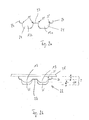
- FIG. 1 shows a microfluidic element 1 with three identically constructed channel structures 2, which extend substantially radially outward.
- the microfluidic element 1 is a test carrier 3, which is formed as a round disc and through which a rotation axis 4 extends centrally to the the disc-shaped test carrier 3 rotates.
- the channel structure 2 is enclosed by a substrate 5 and a cover layer, not shown, which covers the test carrier 3 from above.
- the microfluidic element 1 is suitable for use in an analyzer or similar device having a support for receiving and rotating the microfluidic element.
- the device is preferably designed such that the microfluidic element is rotated about a rotary shaft of the device, wherein the axis of the rotary shaft is aligned with the axis of rotation 4 of the microfluidic element 1.
- the rotary shaft of the device can extend through a bore 4a of the test carrier 3.
- the channel structure 2 of the microfluidic element 1 includes a feed channel 6, which comprises a U-shaped channel section 7 and a straight channel section 8.
- a feed opening 9 is provided, through which a liquid sample, preferably, for example, a body fluid such as blood, can be entered into the feed channel 6.
- a sample liquid can be metered by an operator manually (with a pipette) into a feed opening 9.
- the feed channel can also be equipped with a liquid by means of a dosing station of an analytical device.
- the channel structure 2 further comprises a vent channel 10 with a vent opening 11 and two reagent chambers 13, which are connected to each other via three connecting channels 14 so that a fluid exchange between the two reagent chambers 13 takes place.
- the channel structure 2 is in a preferred embodiment according to FIG. 1 designed as an analysis function channel 15, a measuring chamber 16, a measuring channel 17 between the measuring chamber 16 and the reagent chambers 13 and a waste chamber 18, which is connected via a discharge channel 19 with the measuring chamber 16.
- Waste chamber 18 has an outlet valve 21 through which air from the channel structure 2 can escape.
- the channel structure 2 includes a mixing chamber 22, in which the two reagent chambers 13 and the three connecting channels 14 are integrated.
- the mixing chamber 22 has an inlet opening 23 which is in fluid communication with the feed channel 6, so that a liquid sample can flow into the rotation axis remote reagent chamber 13 a.
- the near-axis reagent chamber 13b is in fluid contact with the vent passage 10 via an air outlet 33, so that air escapes from the reagent chamber assembly and the mixing chamber 22.
- FIG. 2a shows a section along the line IIA FIG. 1 through the two reagent chambers 13a, 13b.
- the reagent chambers 13a, 13b are preferred formed hemispherical, wherein the open opening surface of the hemispheres 24 is completed by the cover layer.
- the reagent chambers 13 are rounded at their bottom so that no sharp edges occur.
- the transitions to the connecting channels are preferably not rounded but sharp-edged, so that a backflow of the liquid from the connecting channel into the (hemispherical) reagent chamber 13 is prevented.
- a sharp edge 25 is formed, wherein the edge 25 preferably includes an angle of 90 °. In this way, a kind of overflow protection is formed, since the edge represents a physical barrier for the further transport of the liquid.
- the reagents present in liquid form are introduced into the open test carrier 3 without cover layer, for example by pipetting.
- the sharp edges then serve as boundaries that prevent creeping of the liquid reagents during drying.
- the structure thus becomes more independent of disturbing effects during automatic processing during drying.
- the surface enlargement by the edges 25 can also have an elongating effect on the mixing time when mixing or dissolving the dry reagents.
- An overflow protection 26 adjoins the reagent chambers 13 at the upper edge, which prevents reagents from escaping from the mixing chamber 22.
- FIG. 2b shows the section through the channel structure 2 FIG. 2a
- the reagent chambers 13 and the mixing chamber 22 is here designed so that the depth t of the overflow protection 26 forms about one third of the depth T of the mixing channel 22.
- the depth t of the overflow protection 26 is about 400 microns.
- Two-thirds of the depth T of the mixing channel 22 is formed by the reagent chambers 13.
- the dried reagent 35 covers the bottom and the inner surfaces of the hemispheres 24, wherein the filling height h of the dry reagent 35 at the bottom corresponds approximately to half the height H of the hemisphere 24.
- the reagent 35 continues to flow up during the drying; it is, however, by the physical Barrier and the edge 25 prevented from further creeping over the web 27 formed between the two chambers 13 a, 13 b.
- the web 27 preferably extends between two adjacent reagent chambers 13 in the direction of the cover layer 34 and thus separates the two reagent chambers 13a, 13b of the mixing chamber 22.
- Figure 2c shows a three-dimensional view in the area of the line IIc FIG. 1 through the connecting channels 14 of the channel structure 2.
- the feed channel 6 has a backstop 28, which is designed as a microfluidic valve 29.
- the depth of the feed channel 6 from the surface 30 of the microfluidic element 1 is significantly less than the depth of the connecting channels 14 and the depth of the rotational axis remote reagent chamber 13 a.
- the depth of the feed channel is about 150 microns.
- a liquid flowing into the overflow protection 26 of the mixing chamber 22 by rotational force from the feed channel 6 flows via the edge 25 into the hemispherical reagent chamber 13a.
- the liquid that has flowed in is moved in the reagent chamber 13a and thus dissolves the dry reagent (not shown here).
- connection channels 14a, 14b and 14c When another liquid flows in, it is also conducted through the connection channels 14a, 14b and 14c into the further reagent chambers 13 (not shown).
- the transitions into the capillary connection channels 14a, 14b, 14c, which are formed by the hemisphere 24, are preferably not smaller than 0.4 ⁇ 0.4 mm in cross section (or their diameter is not smaller than 0.4 mm) and may later taper gradually.
- the capillary force exerted is so great that an overflow (“crosstalk"), in particular of the liquid reagents, before drying out occurs.
- FIG. 3 shows a further embodiment of a test carrier 3, with five identical channel structures 2.
- the feed channel 6 also has a U-shaped channel section 7 and a straight channel section 8.
- the mixing chamber 22 also has a venting channel 10 with a vent 11 at its end close to the axis of rotation.
- the channel structure 2 is designed as an analysis function channel 15 and comprises a measuring chamber 16.
- FIG. 4 shows a detailed drawing of the mixing chamber 22 with the three series-connected reagent chambers 13a, b, c and two connecting channels 14, namely a respective central connecting channel 14a and a lateral (rotation axis near) connecting channel 14b.
- the mixing chamber 22 preferably has a rotational axis-near inlet opening 23, through which liquid from the feed channel 6 enters the mixing chamber 22.
- a capillary transport channel 31 is preferably arranged on the long axis of the mixing chamber 22 remote from the axis of rotation.
- the transport channel 31 extends laterally and radially outward on the series-arranged reagent chambers 13. Its depth (viewed from the surface 30 of the test carrier 3 from) is about 150 to 200 microns less than the depth of the connecting channels.
- the incoming liquid is passed through the transport channel 31 into the reagent chamber 13a.
- the venting channel 10 is wider than the feed channel 8 and as the connecting channels 14 between the reagent chambers 13. In this way, a smaller capillary force is generated by the venting channel 10, so that no liquid penetrates into the venting channel 10.
- the venting channel 10 is always arranged close to the axis of rotation so that the liquid can not pass from the reagent chambers 13 into the venting channel 10 during the rotation.
- the connecting channel 14b on the outside of the mixing chamber 22 is generally used for filling the other reagent chambers 13 with the liquid. Due to the centrally arranged connecting channel 14a, the air contained in the chambers escapes during the filling process.
- the arrangement according to the invention allows the liquids to be mixed even when the reagents are being dissolved, in particular when the reagents in the second and further reagent chambers 13 are being dissolved.
- the degree of solubilization is therefore particularly high and effective.
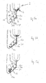
- the filling of the reagent chambers 13 of the mixing channel 22 is based on the FIGS. 5a to 5c explained in more detail.
- Liquid entering the mixing chamber 22 is conducted past the capillary-active transport channel 31 past the two reagent chamber 13b, 13c near the axis of rotation and flows into the reagent chamber 13a remote from the axis of rotation (arrow direction).
- the inflowing liquid is held by capillary action in the transport channel 31.
- the liquid is then pressed at the end remote from the rotation axis of the mixing chamber 22 into the reagent chamber 13a and dissolves the dry reagent contained therein.
- the reagent chambers have a single volume of 3 .mu.l, so that the three reagent chambers together have a volume of about 9 .mu.l.
- the volumes of the individual reagent chambers 13 are preferably between 3 ⁇ l and 10 ⁇ l. Reagent chambers with a volume of 2 ⁇ l or only 1 ⁇ l are also conceivable, as well as reagent chambers 13 with a volume of 20 ⁇ l, 50 ⁇ l, 100 ⁇ l, 500 ⁇ l.
- FIG. 6 shows a further preferred embodiment with a mixing chamber 22, in which two reagent chambers 13a, 13b are integrated. Again, a capillary transport channel 31 is provided, is guided by the liquid entering the mixing chamber 22 to the rotation axis remote reagent chamber 13 a.
- the rounded reagent chambers 13, with the rounded bottoms, which are preferably formed as a hemisphere 24, not only provide for a homogeneous reagent application of the still liquid reagent. They also prove to be extremely suitable when the test carrier 3 is operated in a shake mode in which the rotational speed and direction of rotation are changed according to a preferably sawtooth-shaped control curve.
- the reagent chambers 13 are preferably arranged adjacent to one another such that their distance is smaller than the smallest dimension of the reagent chambers 13 in the test carrier plane, rapid fluid transport from one chamber 13 to the other is also possible.
- the smallest distance is defined in the context of the invention as the smallest distance between the reagent chambers 13 and between the Reagenzhuntau touchcardn.
- At least the centrally located connecting channel 14a between two reagent chambers 13 is therefore shorter than the smallest dimension of the reagent chambers 13.
- the central connecting channel 14a is about 0.2 mm long. Its width and depth are each 0.4 mm.
- the reagent chambers 13 have a height of 1.4 mm.
- the diameter of the reagent chambers is 1.95 mm.
- This geometric arrangement is a fluid transport between two adjacent reagent chambers 13 unhindered possible. Through the short connection channels 14, the fluid can be quickly transported from one chamber to another. The transport takes place directly without intervening valve structures, siphon arrangements or siphon-like channel structures whose length is a multiple of the reagent chambers.
- the process sequence with the reagent chambers according to the invention is very fast and saves time.
- a controlled and defined dissolution of different dry reagents contained in individual reagent chambers 13 can be carried out.
- test carrier 3 Due to the modular design with small reagent chambers 13, it is possible to provide test carrier 3, which are based on this principle arbitrarily expandable. So not only two or three, but also several chambers can be connected in series.
- reagent chambers In addition to the round hemispherical reagent chambers, other forms of the reagent chambers are possible, for example, drop-shaped reagent chamber forms or when using two reagent chambers, which are integrated in a mixing chamber 22 z. B. so-called “yin-yang formations". Preferably, these reagent chambers are rounded.
- FIG. 7 shows a star-shaped arrangement of three reagent chambers 13 in a mixing chamber 22. Also in this arrangement, the rotation axis remote mixing chamber 13a is filled via the transport channel 31 first. If further liquid flows in, then the two reagent chambers 13b, 13c closer to the axis of rotation are filled together. Between the reagent chambers 13a and 13b, only a central connection channel 14a is provided, since the capillary transport channel 31 serves as a second connection channel 14b.
- FIGS. 8a and 8b Three-dimensional views of such a star-shaped reagent chamber arrangement are shown. Clearly visible are the rounded connection channels 14 between the reagent chambers 13 and the rounded hemispherical reagent chambers 13 themselves. In this embodiment, it can be seen that the transport channel 31 also functions fluidically as a connecting channel 14.
- FIG. 9 shows that even a star-shaped or circular arrangement of reagent chambers 13 can be extended.
- six reagent chambers 13 can be interconnected fluidically, whereby the principle is maintained that the rotor axis furthest reagent chamber 13a is filled first. A filling of the other chambers then starts from the rotation axis remote chamber 13a.
- the very compact and small arrangement obtained has the advantage that a plurality of cascaded channel structures 2 can be arranged on a test carrier 3.
Priority Applications (4)
| Application Number | Priority Date | Filing Date | Title |
|---|---|---|---|
| EP09015031A EP2329877A1 (fr) | 2009-12-04 | 2009-12-04 | Elément micro-fluidique destiné à l'analyse d'un échantillon de liquide |
| PCT/EP2010/068499 WO2011067241A1 (fr) | 2009-12-04 | 2010-11-30 | Élément microfluidique pour l'analyse d'un échantillon liquide |
| EP10782320.5A EP2506959B1 (fr) | 2009-12-04 | 2010-11-30 | Elément micro-fluidique destiné à l'analyse d'un échantillon de liquide |
| US13/487,707 US8911684B2 (en) | 2009-12-04 | 2012-06-04 | Microfluidic element for analyzing a liquid sample |
Applications Claiming Priority (1)
| Application Number | Priority Date | Filing Date | Title |
|---|---|---|---|
| EP09015031A EP2329877A1 (fr) | 2009-12-04 | 2009-12-04 | Elément micro-fluidique destiné à l'analyse d'un échantillon de liquide |
Publications (1)
| Publication Number | Publication Date |
|---|---|
| EP2329877A1 true EP2329877A1 (fr) | 2011-06-08 |
Family
ID=42199278
Family Applications (2)
| Application Number | Title | Priority Date | Filing Date |
|---|---|---|---|
| EP09015031A Withdrawn EP2329877A1 (fr) | 2009-12-04 | 2009-12-04 | Elément micro-fluidique destiné à l'analyse d'un échantillon de liquide |
| EP10782320.5A Active EP2506959B1 (fr) | 2009-12-04 | 2010-11-30 | Elément micro-fluidique destiné à l'analyse d'un échantillon de liquide |
Family Applications After (1)
| Application Number | Title | Priority Date | Filing Date |
|---|---|---|---|
| EP10782320.5A Active EP2506959B1 (fr) | 2009-12-04 | 2010-11-30 | Elément micro-fluidique destiné à l'analyse d'un échantillon de liquide |
Country Status (3)
| Country | Link |
|---|---|
| US (1) | US8911684B2 (fr) |
| EP (2) | EP2329877A1 (fr) |
| WO (1) | WO2011067241A1 (fr) |
Cited By (2)
| Publication number | Priority date | Publication date | Assignee | Title |
|---|---|---|---|---|
| EP2532428A3 (fr) * | 2011-06-07 | 2013-04-03 | Robert Bosch Gmbh | Cartouche, centrifugeuse ainsi que procédé de mélange d'un premier et d'un deuxième composant |
| US20150024477A1 (en) * | 2012-05-16 | 2015-01-22 | Panasonic Healthcare Co., Ltd. | Biosensor chip, and biosensor device equipped with same |
Families Citing this family (15)
| Publication number | Priority date | Publication date | Assignee | Title |
|---|---|---|---|---|
| CN105074438B (zh) * | 2012-12-20 | 2018-02-16 | 红外检测公司 | 包括使用比色条形码用于检测分析物的设备和方法 |
| JP6349721B2 (ja) * | 2013-12-24 | 2018-07-04 | 凸版印刷株式会社 | 試料分析チップ |
| EP2952258A1 (fr) * | 2014-06-06 | 2015-12-09 | Roche Diagnostics GmbH | Cartouche rotative pour analyser un échantillon biologique |
| EP2952257A1 (fr) | 2014-06-06 | 2015-12-09 | Roche Diagnostics GmbH | Cartouche rotative pour le traitement et l'analyse d'un échantillon biologique |
| CN106489072B (zh) * | 2014-06-06 | 2019-05-14 | 豪夫迈·罗氏有限公司 | 具有计量室的用于分析生物样品的旋转筒 |
| EP2957890A1 (fr) * | 2014-06-16 | 2015-12-23 | Roche Diagnostics GmbH | Cartouche avec couvercle rotatif |
| WO2017091213A1 (fr) * | 2015-11-24 | 2017-06-01 | Hewlett-Packard Development Company, L.P. | Dispositifs ayant un élément de distribution d'échantillon |
| EP3173149A1 (fr) | 2015-11-26 | 2017-05-31 | Roche Diagnostics GmbH | Détermination d'une quantité d'un analyte dans un échantillon de sang |
| EP4023338A1 (fr) | 2016-04-14 | 2022-07-06 | Roche Diagnostics GmbH | Cartouche et mesure optique d'un analyte avec ladite cartouche |
| CN107305210B (zh) * | 2016-04-20 | 2019-09-17 | 光宝电子(广州)有限公司 | 生物检测卡匣及其检测流体的流动方法 |
| WO2018194700A1 (fr) * | 2017-04-20 | 2018-10-25 | Hewlett-Packard Development Company, L.P. | Système de réaction microfluidique |
| CN108761055B (zh) * | 2018-04-27 | 2024-03-29 | 广州万孚生物技术股份有限公司 | 一种微流控芯片及具有该微流控芯片的分析仪器 |
| CN110295107A (zh) * | 2019-07-01 | 2019-10-01 | 贵州金玖生物技术有限公司 | 一种用于核酸检测的多通量微流控芯片 |
| CN113009136B (zh) * | 2020-08-21 | 2024-04-05 | 东莞东阳光医疗智能器件研发有限公司 | 小型多指标检测样本分析装置 |
| CN114505106B (zh) * | 2022-01-29 | 2023-02-03 | 南京岚煜生物科技有限公司 | 优化磁性混匀效果的主动微流控芯片及其使用方法 |
Citations (4)
| Publication number | Priority date | Publication date | Assignee | Title |
|---|---|---|---|---|
| US20050041525A1 (en) * | 2003-08-19 | 2005-02-24 | Pugia Michael J. | Mixing in microfluidic devices |
| DE102005016509A1 (de) * | 2005-04-09 | 2006-10-12 | Boehringer Ingelheim Microparts Gmbh | Vorrichtung und Verfahren zur Untersuchung einer Probenflüssigkeit |
| EP1944612A1 (fr) * | 2005-11-01 | 2008-07-16 | Matsushita Electric Industrial Co., Ltd. | Disque pour l'analyse d'un echantillon liquide et procede d'analyse d'echantillon liquide melange |
| US20080292502A1 (en) * | 2005-04-04 | 2008-11-27 | Matsushita Electric Industrial Co., Ltd. | Liquid Homogenizer and Analyzer Employing the Same |
Family Cites Families (5)
| Publication number | Priority date | Publication date | Assignee | Title |
|---|---|---|---|---|
| DE3044372A1 (de) | 1980-11-25 | 1982-07-08 | Boehringer Mannheim Gmbh, 6800 Mannheim | Rotoreinheit mit einsatzelementen fuer einen zentrifugalanalysator |
| US4580896A (en) | 1983-11-07 | 1986-04-08 | Allied Corporation | Multicuvette centrifugal analyzer rotor with annular recessed optical window channel |
| GB9809943D0 (en) | 1998-05-08 | 1998-07-08 | Amersham Pharm Biotech Ab | Microfluidic device |
| SE0201738D0 (sv) | 2002-06-07 | 2002-06-07 | Aamic Ab | Micro-fluid structures |
| EP1916524A1 (fr) * | 2006-09-27 | 2008-04-30 | Roche Diagnostics GmbH | Elément d'essai rotatif |
-
2009
- 2009-12-04 EP EP09015031A patent/EP2329877A1/fr not_active Withdrawn
-
2010
- 2010-11-30 EP EP10782320.5A patent/EP2506959B1/fr active Active
- 2010-11-30 WO PCT/EP2010/068499 patent/WO2011067241A1/fr active Application Filing
-
2012
- 2012-06-04 US US13/487,707 patent/US8911684B2/en active Active
Patent Citations (4)
| Publication number | Priority date | Publication date | Assignee | Title |
|---|---|---|---|---|
| US20050041525A1 (en) * | 2003-08-19 | 2005-02-24 | Pugia Michael J. | Mixing in microfluidic devices |
| US20080292502A1 (en) * | 2005-04-04 | 2008-11-27 | Matsushita Electric Industrial Co., Ltd. | Liquid Homogenizer and Analyzer Employing the Same |
| DE102005016509A1 (de) * | 2005-04-09 | 2006-10-12 | Boehringer Ingelheim Microparts Gmbh | Vorrichtung und Verfahren zur Untersuchung einer Probenflüssigkeit |
| EP1944612A1 (fr) * | 2005-11-01 | 2008-07-16 | Matsushita Electric Industrial Co., Ltd. | Disque pour l'analyse d'un echantillon liquide et procede d'analyse d'echantillon liquide melange |
Cited By (4)
| Publication number | Priority date | Publication date | Assignee | Title |
|---|---|---|---|---|
| EP2532428A3 (fr) * | 2011-06-07 | 2013-04-03 | Robert Bosch Gmbh | Cartouche, centrifugeuse ainsi que procédé de mélange d'un premier et d'un deuxième composant |
| US9475043B2 (en) | 2011-06-07 | 2016-10-25 | Robert Bosch Gmbh | Cartridge, centrifuge and method for mixing a first and second component |
| US20150024477A1 (en) * | 2012-05-16 | 2015-01-22 | Panasonic Healthcare Co., Ltd. | Biosensor chip, and biosensor device equipped with same |
| US10023897B2 (en) * | 2012-05-16 | 2018-07-17 | Phc Holdings Corporation | Biosensor chip, and biosensor device equipped with same |
Also Published As
| Publication number | Publication date |
|---|---|
| US20120301371A1 (en) | 2012-11-29 |
| US8911684B2 (en) | 2014-12-16 |
| EP2506959B1 (fr) | 2015-02-25 |
| WO2011067241A1 (fr) | 2011-06-09 |
| EP2506959A1 (fr) | 2012-10-10 |
Similar Documents
| Publication | Publication Date | Title |
|---|---|---|
| EP2506959B1 (fr) | Elément micro-fluidique destiné à l'analyse d'un échantillon de liquide | |
| DE60124699T2 (de) | Zweirichtungs-durchfluss-zentrifugalmikrofluid-vorrichtungen | |
| EP2072131B1 (fr) | Elément microfluide destiné au mélange d'un liquide dans un réactif | |
| DE112011102770B4 (de) | Mikrofluidische Einheit mit Hilfs- und Seitenkanälen | |
| DE602004013339T2 (de) | Mischen in mikrofluidvorrichtungen | |
| EP2632591B1 (fr) | Élément microfluidique pour l'analyse d'un échantillon liquide | |
| DE19947495C2 (de) | Mikrofluidischer Mikrochip | |
| EP1201304B1 (fr) | Plateforme microstructurée pour l'examen d'un liquide | |
| DE60035611T2 (de) | Mikrofluid-analysevorrichtung | |
| DE102013203293B4 (de) | Vorrichtung und Verfahren zum Leiten einer Flüssigkeit durch einen ersten oder zweiten Auslasskanal | |
| EP1566215A2 (fr) | Plateforme microstructurée et procédé de manipulation d'un liquide | |
| DE10352535A1 (de) | Mikrostrukturierte Trennvorrichtung und Verfahren zum Abtrennen von flüssigen Bestandteilen aus einer Partikel enthaltenden Flüssigkeit | |
| DE112018007590B3 (de) | Anwendungsspezifisch ausgestaltbare mikrofluidik-einheit mit programmierbaren mikrofluidik-knoten | |
| DE102009048378B3 (de) | Mikrofluidische Struktur | |
| EP2062643A1 (fr) | Système d'analyse et procédé d'analyse d'un échantillon de liquide corporel sur un analyte contenu dans celui-ci | |
| EP3829767B1 (fr) | Dispositif et procédé destinés à conduire un liquide à travers un milieu poreux | |
| DE112015006185T5 (de) | Mikrofluidik-Einheit mit longitudinalen und transversalen Flüssigkeitsbarrieren zur transversalen Strömungsvermischung | |
| DE2117423C3 (fr) | ||
| DE102007019695A1 (de) | Küvette für die optische Analyse kleiner Volumina | |
| DE102019209746A1 (de) | Mikrofluidische Vorrichtung zum Prozessieren und Aliquotieren einer Probenflüssigkeit, Verfahren und Steuergerät zum Betreiben einer mikrofluidischen Vorrichtung und mikrofluidisches System zum Durchführen einer Analyse einer Probenflüssigkeit | |
| DE102008002509A1 (de) | Stopped-Flow-Chip | |
| DE60007285T2 (de) | Gerät zum kapillaren flüssigkeitstransfer in seinem inneren | |
| DE102009001257A1 (de) | Vorrichtung und Verfahren zur Handhabung von Flüssigkeiten | |
| WO2018011085A1 (fr) | Manipulation de liquides en utilisant un module fluidique présentant un plan fluidique incliné par rapport à un plan de rotation | |
| EP1534432B1 (fr) | Systemes microfluidiques a rapport de forme eleve |
Legal Events
| Date | Code | Title | Description |
|---|---|---|---|
| PUAI | Public reference made under article 153(3) epc to a published international application that has entered the european phase |
Free format text: ORIGINAL CODE: 0009012 |
|
| AK | Designated contracting states |
Kind code of ref document: A1 Designated state(s): AT BE BG CH CY CZ DE DK EE ES FI FR GB GR HR HU IE IS IT LI LT LU LV MC MK MT NL NO PL PT RO SE SI SK SM TR |
|
| AX | Request for extension of the european patent |
Extension state: AL BA RS |
|
| STAA | Information on the status of an ep patent application or granted ep patent |
Free format text: STATUS: THE APPLICATION IS DEEMED TO BE WITHDRAWN |
|
| 18D | Application deemed to be withdrawn |
Effective date: 20111209 |