EP2328698B1 - Method for forming a sector for a nacelle lip skin - Google Patents
Method for forming a sector for a nacelle lip skin Download PDFInfo
- Publication number
- EP2328698B1 EP2328698B1 EP09776784A EP09776784A EP2328698B1 EP 2328698 B1 EP2328698 B1 EP 2328698B1 EP 09776784 A EP09776784 A EP 09776784A EP 09776784 A EP09776784 A EP 09776784A EP 2328698 B1 EP2328698 B1 EP 2328698B1
- Authority
- EP
- European Patent Office
- Prior art keywords
- blank
- punch
- gripping
- gripping means
- clamping
- Prior art date
- Legal status (The legal status is an assumption and is not a legal conclusion. Google has not performed a legal analysis and makes no representation as to the accuracy of the status listed.)
- Not-in-force
Links
Images


Classifications
-
- B—PERFORMING OPERATIONS; TRANSPORTING
- B21—MECHANICAL METAL-WORKING WITHOUT ESSENTIALLY REMOVING MATERIAL; PUNCHING METAL
- B21D—WORKING OR PROCESSING OF SHEET METAL OR METAL TUBES, RODS OR PROFILES WITHOUT ESSENTIALLY REMOVING MATERIAL; PUNCHING METAL
- B21D53/00—Making other particular articles
- B21D53/92—Making other particular articles other parts for aircraft
-
- B—PERFORMING OPERATIONS; TRANSPORTING
- B21—MECHANICAL METAL-WORKING WITHOUT ESSENTIALLY REMOVING MATERIAL; PUNCHING METAL
- B21D—WORKING OR PROCESSING OF SHEET METAL OR METAL TUBES, RODS OR PROFILES WITHOUT ESSENTIALLY REMOVING MATERIAL; PUNCHING METAL
- B21D25/00—Working sheet metal of limited length by stretching, e.g. for straightening
- B21D25/02—Working sheet metal of limited length by stretching, e.g. for straightening by pulling over a die
-
- B—PERFORMING OPERATIONS; TRANSPORTING
- B21—MECHANICAL METAL-WORKING WITHOUT ESSENTIALLY REMOVING MATERIAL; PUNCHING METAL
- B21D—WORKING OR PROCESSING OF SHEET METAL OR METAL TUBES, RODS OR PROFILES WITHOUT ESSENTIALLY REMOVING MATERIAL; PUNCHING METAL
- B21D25/00—Working sheet metal of limited length by stretching, e.g. for straightening
- B21D25/04—Clamping arrangements
Definitions
- This invention relates to method and apparatus for forming compound curvature metal skins and in particular to a method and apparatus for forming a nacelle cowl leading edge (hereinafter referred to as a "lip skin”) or a sector thereof from a single metal blank.
- a nacelle cowl leading edge hereinafter referred to as a "lip skin”
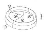
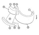
- a typical nacelle lip skin is illustrated in Fig. 1 .
- the nacelle comprises a thin, aerodynamically shaped metal skin covering a jet engine of an aircraft.
- the front region of the nacelle comprises a lip skin defining the inlet of the engine, which may be comprised of a single piece or multiple sectors.
- the main features of the lip skin are a smooth outer trailing edge 1, which must be free from irregularities and discontinuities to reduce drag and to avoid the creation of turbulence and an inner inlet edge 2, which is typically shaped to attenuate noise from the engine by shielding fan noise and to guide the flow of air into the engine, and a leading edge or lip 3, which provides a smooth transition between the outer trailing edge and the inner inlet edge while creating a small frontal area to reduce drag.
- the lip skin and in particular the leading edge 3 thereof, is prone to damage from debris kicked up during take off and landing and by bird strike. If the lip skin of the nacelle is damaged, the damaged section must be replaced. Typically this necessitates cutting out the damaged section and cutting a corresponding section 4 from a replacement lip skin, or alternatively replacement of the entire nacelle lip skin.
- the lip skin must generally be made from a metal, such as aluminium or titanium, to be able to withstand impacts upon the leading edge or lip thereof.
- a metal such as aluminium or titanium
- the complex three dimensional compound curvature shape of the lip skin typically requires a complex multi-stage forming process, often requiring intermediate heat treatments.
- lip skins are produced by multiple stage deep drawings or spin forming processes, requiring complex and costly tooling and time consuming multistep processing with intermediate heat treatments.
- such known processes are generally only suitable for forming complete annular lip skins and thus cannot readily be used to produce separate sectors required to repair specific damaged sectors of a nacelle lip skin.
- a method of forming a sector of a nacelle lip skin from a sheet metal blank comprising the steps of :-
- the method comprises the further step of further displacing the gripping means in said second direction while preventing the blank from being drawn through said gripping means to stretch the blank over the surface of the punch.
- said further step further comprises axially displacing said clamping means relative to the punch in said second direction to further stretch the blank over the surface of the punch.
- the blank is prevented from being drawn through the gripping means by abutting a leading edge of the gripping means against a gripping member having an axial gripping face adapted to cooperate with a leading edge the gripping means to clamp the blank therebetween.
- a method of forming a lip skin of a nacelle from a metal blank comprising forming the blank into a curved shaped having a radius corresponding to the radius of the outer surface of a punch and clamping one side of the blank at or adjacent said outer surface, clamping an opposite curved side of the blank in a gripping means comprising first and second gripping members located adjacent and in front of a leading edge of the punch, said first and second gripping members holding said blank with sufficient force to permit the blank to flow in a controlled manner between the gripping members without tearing or wrinkling, moving the gripping means in a first direction, substantially radially inwardly with respect to the axis of the punch, to draw the blank over the leading edge of the punch, subsequently moving the gripping means in a second direction, transverse to said first direction and substantially axially with respect to the axis of the punch, to draw the blank around the leading edge of the punch.
- the method comprises the further step of preventing flow of the blank between the first direction, substantially radially
- an apparatus for forming a sector of a lip skin comprising :-
- the punch may comprise an annular body, replicating an entire nacelle lip skin.
- the punch may comprise an arcuate sector corresponding to a sector of the lip skin to be formed.
- the punch may be non-axisymmetric to enable the formation of a sector of an non-axisymmetric lip skin.
- the punch may be rotatable with respect to the gripping means and the clamping means to enable the punch to be indexed with respect to the gripping means and clamping means to the correct position corresponding to the sector of the lip skin to be formed.
- the present invention provides a method and apparatus for forming a sector of a nacelle lip skin which overcomes the disadvantages of the prior art and is of particular benefit for nacelle repairs by facilitating the quick and easy creation of a replacement sector of a lip skin to replace a damaged sector. While the present invention is particularly described in relation to nacelle lip skins for aircraft, the method and apparatus according to the invention can also be used for the manufacture of other standard or laminar flow leading edges for a variety of applications.
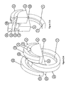
- a tool for forming a nacelle lip skin in accordance with a first embodiment of the present invention comprises a tool base 6 for supporting the other components of the tool.
- An annular punch 7 is supported on an outer edge of the tool base.
- the tool base 6 may comprise a full 360° disc shaped core having an outer lip for supporting an inner edge of the punch 7 or may comprise a sector, for example a 180° sector supporting just an upper portion of the punch 7.
- the annular punch 7 has an outer surface, a leading edge and an inner surface having a shape corresponding to the inner surface of the finished lip skin.
- the punch 7 may correspond to a sector of the lip skin, for example a 180° sector, or may comprise a full 360° annulus corresponding to the entire lip skin.
- the punch 7 may be rotated with respect to the tool base 6 to index the punch relative to the rest of the tool so that the region of the punch corresponding to the sector of the lip skin to be produced is used for formation of the sector. This facilitates the formation of sectors of non-axisymmetric lip skins.
- An arcuate blank holder 8 is located adjacent to and axially spaced from the tool base 6.
- the outer surface of the blank holder 8 may be provided with a replaceable wear plate 14 against which the blank 13 is slidable.
- An arc die 9 is adapted to cooperate with the blank holder 8 to engage a blank 13 therebetween, as will be described in more detail below.
- the arc die 9 has an inner surface adapted to fit against an outer surface of the blank holder 8, more specifically the wear plate 14 provided thereon, with a portion of the blank 13 interposed therebetween.
- the inner surface of the arc die 9 may be provided with a replaceable wear surface 15.
- a drive mechanism for radially moving the arc die 9 with respect to the blank holder 8 may be housed within the blank holder 8.
- the drive mechanism may comprise one or more double acting rams.
- a lubricant dispensing means may be provided for dispensing a lubricant between the blank and the facing surfaces of the blank holder 8 and the arc die 9 to assist drawing of the blank therebetween.
- the arc die 9 has a leading edge 18 adjacent to the leading edge of the punch 7 and a stepped outer surface, having a first portion 16 adjacent to the leading edge 18 having an external radius corresponding to the inner radius of the punch 7 such that the first portion 16 of the arc die can telescopically move into the centre of the punch 7, and a thicker second section, distal from said leading edge, to provide sufficient tool stiffness.
- the shape of the second section may be adapted to provide the required stiffness to obtain an even clamping force across the width of the blank 13.
- the leading edge 18 of the arc die 9 is filleted to minimise wrinkling and ensure a smooth draw process.
- An internal arc grip 10 is mounted on a front face of the tool base 6 to cooperate with the leading edge 18 of the arc die 9 to clamp the blank 13 therebetween in a final stretch forming step, as will be described in more detail below.
- the surface of the arc grip 10 may be textured or otherwise formed or modified to ensure that the blank 13 can be gripped without slippage.
- a transfer arc grip 12 (inner) and a coaxial external arc grip 11 (outer) are mounted adjacent to the punch 7, supported on the rear of the tool base 6, to firmly clamp a side region of the blank 13 therebetween at a trailing edge of the blank 13 to locate the blank 13 against the outer side of the punch 7.
- the clamping surfaces 20,21 of the external and transfer arc grips 11,12 may be textured or otherwise formed or modified to ensure that the blank 13 is gripped without slippage.
- the clamping surfaces 20,21 of the external and transfer arc grips may be defined by replaceable wear surfaces.
- Each of the transfer arc grip 12 and the coaxial external arc grip 11 may extend through an angle sufficient to grip the width of the blank 13 to be formed.
- the minimum width of the clamping surfaces 20,21 should preferably correspond to the width of the widest sector of lip skin to be formed by the tool.
- the external and transfer arc grips 11,12, as well as the blank holder 8 and the arc die 9, extend through an angle of 180°. However, this is only illustrated by example and the angular extent of such components may vary.
- Adequate stiffness is ensured by the use of a stepped thickness cross section of the external and transfer arc grips 22, 12.
- the clamping surfaces 20,21 external arc grip 11 and transfer arc grip 12 firmly hold said side region of the blank 13 throughout the forming process.
- Actuators are provided for radially moving the external arc grip 11 and the transfer arc grip 12 relative to each other and to provide the required clamping force.
- the external arc grip 11 may act directly on a portion of the outer surface of the punch 7 to clamp the blank 13 thereagainst.
- a differential drive mechanism is provided between the transfer arc grip 12 and the internal arc grip 10 for controlling displacement of the transfer arc grip away from the tool base 6 as a function of the displacement of the internal arc grip towards the tool base during a final stretch forming step, as will be described below.
- the differential drive mechanism may comprise a closed fluid filled chamber having different diameter or cross-sectional area pistons slidably mounted therein acting against the transfer arc grip 12 and internal arc grip 10, such displacement of internal arc grip towards the tool base 6 results in a relatively smaller displacement of the transfer arc grip 12 away from the tool base 6. This differential displacement will be important to achieve the desired final stretch process.
- a system of gearing and/or a cam and cam follower arrangement may be provided for transmitting movement between the internal arc grip 10 and the transfer arc grip 12.
- the radius of the clamping surface 20 of the external arc grip 11 is equal to the radius of the trailing edge of the finished lip skin sector.
- the radius of the clamping surface 21 of transfer arc grip 12 will be the minimum value of the trailing edge radius of the lip skin. At radial positions where there is a mismatch in radii, suitable blending fillets may be used.
- the transfer arc grip 12 may comprise a full 360° annular member corresponding to the annular punch 7 and indexable therewith.
- the external arc grip 11 may be formed from a flexible segmented member allowing the external arc grip 11 to conform to the shape of the relevant sector of the transfer arc grip 12.
- the overall size of the blank 13 will be determined from the required sector size and the required draw during the forming process.
- the minimum size of material should be used to ensure near net shape forming.
- the "flow" of material can be further enhanced using a profiled blank.
- a method for forming a sector of a nacelle lip skin using the tool described above is as follows.
- the punch 7 (and the transfer arc grip 12 if appropriate) is indexed to the correct position corresponding to the sector of the lip skin to be formed.
- a blank 13 is placed against the outer surface of the punch 7 and in contact with the blank holder 8.
- it may require a pre-form rolling operation to a curvature having a radius substantially equal to the radius of the outer surface of the punch 7.
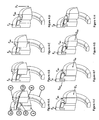
- the blank 13 is positioned with one end of the blank 13 located between the transfer arc grip 12 and the external arc grip 11 and an opposite end of the blank 13 between the blank holder 8 and the arc die 9, as shown in Fig. 4A .
- a clamping force F G is applied between the external arc grip 11 and the transfer arc grip 12 to fully grip the blank 13 therebetween without slippage, as shown in Fig. 4B .
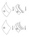
- the blank shape at this stage is illustrated in Fig. 5A .
- a clamping force F BH is next applied between the arc die 9 and the blank holder 8 sufficient to permit the blank 13 to flow in a controlled manner between the blank holder 8 and the arc die 9 without tearing or wrinkling, as shown in Fig. 4C .
- the blank holder 8 remains stationary with respect to the tool base 6 and punch 7 during this stage.
- the blank shape at this stage is illustrated in Fig. 5B .
- the blank 13 flows, in a regulated manner between the blank holder 8 and the arc die 9 and is shaped over the leading edge of the punch 7 to create the blank shape illustrated in Fig. 5C .
- the blank holder 8 and the arc die 9 are displaced horizontally, by a distance D H , towards and past the leading edge of the punch 7 while maintaining said controlled clamping force F BH between the arc die 9 and the blank holder 8, as shown in Fig 4E .
- the blank 13 flows, in a regulated manner from between the tool holder 8 and the arc die 9 while reverse drawing around the leading edge 18 of the arc die 9.
- the blank shape at this stage is illustrated in Fig. 5D .
- Such motion may be obtained by moving the punch 7 with respect to the blank holder 8.
- the action of the arc die 9 against the internal arc grip 10 is transmitted through the differential drive mechanism to cause the transfer arc grip 12 and the external arc grip 11 to be displaced with respect to the tool base 6/punch 7 by a distance S OH while maintaining the gripping force F G , as shown in Fig. 4F .
- the ratio of S IH to S OH determined by the differential drive mechanism, is critical to the final stretch operation to achieve the required final form without creases, tears or wrinkling and minimal springback.
- the clamping force F BH between the tool holder 8 and the arc die 9 is released and the blank holder 8 and arc die 9 are retracted, as shown in Fig. 4G .
- the clamping force F G between the transfer arc grip 12 and the external arc grip 11 is released and the external arc grip 11 is retracted away from the transfer arc grip 12 to release the formed part, as shown in Fig. 4H .
- the final lip skin can be produced by cutting away the parts of the blank 13 held by the external arc grip 11 and internal arc grip 10 so that the final product is devoid of tool marks.
- a second embodiment of the present invention alleviates these problems by utilising a conical blank 13 and profiling the blank holder 8 and arc die 9 and the external and transfer arc grips 10,11 to define conical gripping surfaces holding the blank substantially parallel to a line extending from a trailing edge of the punch 7 (substantially corresponding to a trailing edge of the finished lip skin) to a leading edge of the front of the punch 7 (i.e. the apex of the leading edge of the lip skin).
- like reference numerals are used to describe like parts between the two embodiments.
- the apparatus according to the second embodiment of the invention is similar to the first embodiment in many details, comprising an annular punch 7 supported on a tool base (not shown).
- the annular punch 7 has an outer surface, a leading edge and an inner surface having a shape corresponding to the inner surface of the finished lip skin.
- the punch 7 may correspond to a sector of the lip skin, for example a 180° sector, or may comprise a full 360° annulus corresponding to the entire lip skin.
- the punch 7 may be rotated with respect to the tool base (not shown) to index the punch relative to the rest of the tool so that the region of the punch corresponding to the sector of the lip skin to be produced is used for formation of the sector. This facilitates the formation of sectors of non-axisymmetric lip skins.
- a blank holder 8 is located adjacent and axially spaced from the tool base.
- the outer surface 14 of the blank holder 8 comprising a 180° of a truncated cone having an outer surface shaped to mate with the conical blank.
- An arc die 9 is provided having an inner surface adapted to cooperate with the outer surface of the blank holder 8 to permit the blank to flow in a controlled manner from between the blank holder 8 and arc die 9 without tearing or wrinkling.
- the outer radius of the arc die 9 is adapted to allow the arc die 9 to pass inside of the annular punch 7 with sufficient clearance to ensure that the blank does not become trapped between the outer surface of the arc die 9 and the inner surface of the punch 7.
- the front face 18 of the arc die 9 is shaped to allow the blank to be drawn over the front face of the arc die 9 to minimise wrinkling and to ensure a smooth draw/redraw process.
- An actuating mechanism is provided for moving the arc die 9 horizontally with respect to the blank holder 8 to clamp the blank 13 therebetween.
- the transfer arc grip 12 and external arc grip 11 are provided with conical mating surfaces for gripping a trailing edge of the blank 13.
- the mating faces of the transfer arc grip 12 and external arc grip 11 are appropriately textured to preclude slippage. Adequate stiffness is ensured by the use of a conical section.
- the transfer arc grip 12 and external arc grip 11 clamp the blank 13 adjacent to its trailing edge throughout the forming operation.
- the conical surface 20 of the transfer arc grip 12 is coincident with the trailing edge of the blank 13.
- the conical surface 20 of the transfer arc grip 12 corresponds to the minimum radius of the trailing edge of the punch 7.
- suitable blending fillets may be used.
- the transfer arc grip 12 may be formed as a full 360° surface following the radial variations of the punch 7.
- the external arc grip 11 may be formed as a segmented member having sufficient flexibility to conform to the shape of the transfer arc grip 12.
- the internal arc grip 10 is arranged with a clamping face adapted to abut the leading edge of the arc die 9 to provide a final stretching process.
- the internal arc grip 10 is linked to the transfer arc grip 12 by a differential displacement drive, comprising suitable gearing of hydraulic linkages (with differential diameter pistons) in the same manner as the first embodiment, as will de described below.
- the blank 13 has a size determined from the required sector size and the required draw during the forming process.
- the minimum material size is used to ensure near net shape forming.
- the flow of the material may be enhanced further by using a profiled blank.
- the conical profile of the blank 13 may be produced during the process or may be formed by an initial pre-forming process, for example by a roll bending operation.
- the conical surfaces of the transfer arc grip 12 and external arc grip 11 and of the blank holder 8 and arc die 9 provide a variable pressure clamping effect that can compensate for material thickness variability.
- the blank holder 8, arc die 9 and transfer and external arc grip 10,11 are arranged with respect to the punch 7 so that the central axis 23 of the punch 7 is inclined with respect to the central axis 24 of the blank 13 to so that the blank is substantially parallel to a line extending between a trailing edge of the outer surface of the punch 7 and the leading edge of the front of the punch when the blank 13 is initially placed into the tooling.
- a blank is placed between the transfer arc grip 12 and external arc grip 11 at a trailing end and between the blank holder 8 and arc die 9 at a leading end.
- the blank may require a pre-form rolling operation to produce a conical profile shaped to fit against the outer surface of the die 7 and to fit within the tooling.
- the initial rolling operation will provide a stiffer component that is easier to manipulate during the loading process.
- the blank shape is illustrated in Figure 8A .
- the external arc grip 11 is moved in an axial direction by suitable actuators to clamp the blank between the transfer arc grip 12 and external arc grip 11 and a sufficient force F G is applied to grip the blank without slippage, as shown in Figure 8B .
- the optimal line of force action (i.e. movement) of the external arc grip is aligned with central axis 24 of the blank when initially placed within the tooling.
- the external arc grip 11 may be moveable in other directions, including parallel to the axis of the die or substantially perpendicular to said axis.
- the arc die 9 is moved, by suitable actuators, towards the blank holder 8 to grip the blank therebetween.
- a force F BH is applied to sufficient to permit the blank to flow in a controlled manner from between the blank holder 8 and arc die 9 without tearing or wrinkling.
- the optimum direction of movement of the arc die 9, and hence the application of force F BH is aligned with the central axis of the blank 24, as shown in Figure 8C .
- the blank holder 8 and arc die 9 and the internal arc grip 10 and external arc grip 11 are displaced in a first direction towards the central axis of the punch 7 in a substantially downwards direction as a complete assembly by a distance D v while maintaining the controlled force F BH between the blank holder 8 and arc die 9 and the clamping force F G between the internal arc grip 8 and external arc grip 11.
- the blank flows between the blank holder 8 and arc die 9, as shown in Figure 8D .
- the blank holder 8 and arc die 9 may be held stationary and the punch 7 and associated components may be moved with respect to the blank holder 8.
- the rear edge 18 of the arc die 9 comes into contact with the internal arc grip 10 to grip the blank therebetween without slippage and continued horizontal movement of the arc grip differentially drives the transfer and external arc grips 10,11 to perform a final stretching operation upon the blank.
- the arc die 9 and internal arc grip 10 move through a distance S OH while the transfer arc grip 10 and external arc grip 11 move through a distance S IH , as shown in Figure 8G .
- the differential displacement mechanism ensures that a critical ratio of S OH to S IH is achieved to obtain the required final stretch without tearing or wrinkling of the blank.
- the clamping force F BH is released to release the blank 13 and the arc die 9 and outer arc grip 11 are moved horizontally by a distance D RH to release the formed blank 13 from the tooling, as shown in Figure 8H .
- the present invention provides an improved single stage process and apparatus for forming a sector of a lip skin where the most important section of the lip skin from an aerodynamic point of view, namely the outer trailing edge is exposed to the minimum of stretching and bending and is free from clamping or tool marks. Because the part of the blank forming the outer trailing edge of the finished lip skin is largely unaffected by the forming process, the present invention can readily form laminar flow leading edges having a trailing edge whose axial length from the leading edge is of much greater length than that achievable with known forming methods.
Landscapes
- Engineering & Computer Science (AREA)
- Mechanical Engineering (AREA)
- Aviation & Aerospace Engineering (AREA)
- Shaping Metal By Deep-Drawing, Or The Like (AREA)
Priority Applications (1)
| Application Number | Priority Date | Filing Date | Title |
|---|---|---|---|
| PL09776784T PL2328698T3 (pl) | 2008-07-10 | 2009-06-19 | Sposób kształtowania sektora noska poszycia gondoli |
Applications Claiming Priority (2)
| Application Number | Priority Date | Filing Date | Title |
|---|---|---|---|
| GBGB0812614.6A GB0812614D0 (en) | 2008-07-10 | 2008-07-10 | Metal forming |
| PCT/EP2009/004434 WO2010003538A1 (en) | 2008-07-10 | 2009-06-19 | Method for forming a sector for a necelle lip skin |
Publications (2)
| Publication Number | Publication Date |
|---|---|
| EP2328698A1 EP2328698A1 (en) | 2011-06-08 |
| EP2328698B1 true EP2328698B1 (en) | 2012-09-19 |
Family
ID=39722044
Family Applications (1)
| Application Number | Title | Priority Date | Filing Date |
|---|---|---|---|
| EP09776784A Not-in-force EP2328698B1 (en) | 2008-07-10 | 2009-06-19 | Method for forming a sector for a nacelle lip skin |
Country Status (12)
| Country | Link |
|---|---|
| US (1) | US9021848B2 (enExample) |
| EP (1) | EP2328698B1 (enExample) |
| JP (1) | JP5781927B2 (enExample) |
| CN (1) | CN102149489B (enExample) |
| BR (1) | BRPI0915555B1 (enExample) |
| CA (1) | CA2730356C (enExample) |
| DK (1) | DK2328698T3 (enExample) |
| ES (1) | ES2394060T3 (enExample) |
| GB (1) | GB0812614D0 (enExample) |
| PL (1) | PL2328698T3 (enExample) |
| PT (1) | PT2328698E (enExample) |
| WO (1) | WO2010003538A1 (enExample) |
Families Citing this family (24)
| Publication number | Priority date | Publication date | Assignee | Title |
|---|---|---|---|---|
| WO2012116999A1 (en) * | 2011-02-28 | 2012-09-07 | Globally Local Solutions Limited | A lip skin and a method and apparatus for forming a lip skin |
| GB201301627D0 (en) * | 2013-01-30 | 2013-03-13 | Globally Local Solutions Ltd | A lip skin sector and a method and apparatus for forming a lip skin sector |
| CN103272909B (zh) * | 2013-06-14 | 2015-05-13 | 沈阳飞机工业(集团)有限公司 | 一种保证化铣厚蒙皮制件质量的成形方法 |
| GB201312228D0 (en) * | 2013-07-08 | 2013-08-21 | Ludlow Michael | A lip skin and a method and apparatus for forming a lip skin |
| US9708072B2 (en) | 2014-04-30 | 2017-07-18 | The Boeing Company | Aircraft engine nacelle bulkheads and methods of assembling the same |
| US9604438B2 (en) | 2014-04-30 | 2017-03-28 | The Boeing Company | Methods and apparatus for noise attenuation in an engine nacelle |
| US9938852B2 (en) | 2014-04-30 | 2018-04-10 | The Boeing Company | Noise attenuating lipskin assembly and methods of assembling the same |
| US9656761B2 (en) * | 2014-04-30 | 2017-05-23 | The Boeing Company | Lipskin for a nacelle and methods of making the same |
| GB201505690D0 (en) * | 2015-04-02 | 2015-05-20 | Univ Ulster | Method and apparatus for forming a compound curvature metal skin |
| GB201519064D0 (en) * | 2015-10-28 | 2015-12-09 | Lenis Aer Ltd | A lip skin sector and a method and apparatus for forming a lip skin sector |
| US10428763B2 (en) | 2016-04-01 | 2019-10-01 | Rohr, Inc. | Controlling a relative position at an interface between translating structures of an aircraft nacelle |
| US11046034B2 (en) | 2016-04-18 | 2021-06-29 | Rohr, Inc. | Manufacturing a fiber-reinforced composite component using mandrels |
| US10793282B2 (en) | 2016-07-28 | 2020-10-06 | The Boeing Company | Liner assembly, engine housing, and methods of assembling the same |
| US10525636B2 (en) | 2017-06-19 | 2020-01-07 | Rohr, Inc. | Process for forming a fiber-reinforced composite structure |
| US10589869B2 (en) * | 2018-07-25 | 2020-03-17 | General Electric Company | Nacelle inlet lip fuse structure |
| CN109692911B (zh) * | 2018-12-10 | 2020-10-16 | 上海航天设备制造总厂有限公司 | 一种大型环壳零件整体成形装置和方法 |
| US11065668B2 (en) * | 2019-02-01 | 2021-07-20 | Rohr, Inc. | Method and apparatus for forming a nacelle leading edge |
| CN111113793B (zh) * | 2019-12-20 | 2021-11-16 | 苏州奥正智精密机械有限公司 | 一种非标准件的加工工艺 |
| US20210237139A1 (en) * | 2020-02-03 | 2021-08-05 | Rohr, Inc. | Methods and assemblies for forming an annular object |
| FR3115222B1 (fr) * | 2020-10-21 | 2023-05-12 | Safran Nacelles | Fabrication de secteurs annulaires pour la réalisation d’une lèvre d’entrée d’air |
| FR3115223B1 (fr) * | 2020-10-21 | 2023-05-12 | Safran Nacelles | Fabrication d’une lèvre d’entrée d’air ou d’un secteur annulaire de lèvre d’entrée d’air intégrant des ouvertures à bord rentré |
| CN114210797B (zh) * | 2021-12-17 | 2023-11-14 | 湖北三江航天红阳机电有限公司 | 一种钛合金筒形蒙皮圆弧预弯及校形方法 |
| GB2618123A (en) * | 2022-04-28 | 2023-11-01 | Rohr Inc | A method and arrangement for forming a lip skin for a nacelle |
| EP4275835B1 (en) * | 2022-05-12 | 2024-12-04 | Creuzet Aeronautique | Inlet lip skin manufacturing method |
Family Cites Families (17)
| Publication number | Priority date | Publication date | Assignee | Title |
|---|---|---|---|---|
| US2242204A (en) * | 1939-02-13 | 1941-05-13 | Homer R Kennedy | Sheet metal forming machine |
| US2678638A (en) * | 1948-11-01 | 1954-05-18 | Cecil W Bopp | Fluid stop for fluid motors |
| US2676638A (en) * | 1952-07-26 | 1954-04-27 | Richard Seifried | Stretch-wrap forming machine |
| JPS6313626A (ja) * | 1986-07-04 | 1988-01-20 | Amino Tekkosho:Kk | リツプスキン類の成形法及び装置 |
| US5035133A (en) * | 1990-02-09 | 1991-07-30 | Rohr Industries, Inc. | Method and apparatus for hot die draw forming metal sheets |
| JPH0857548A (ja) * | 1994-08-23 | 1996-03-05 | Kawasaki Yukou Kk | 断面積が変化する材料のストレッチ成形方法 |
| FR2729007B1 (fr) * | 1994-12-29 | 1997-01-24 | Bull Sa | Dispositif de cambrage de pattes conductrices d'un support intermediaire de circuit integre |
| US5735160A (en) * | 1997-04-15 | 1998-04-07 | Aluminum Company Of America | Stretch forming metal bodies with polymeric internal mandrels |
| US5737953A (en) * | 1997-03-18 | 1998-04-14 | Aluminum Company Of America | Process for stretch forming hollow metal bodies |
| US6675624B2 (en) * | 2000-07-13 | 2004-01-13 | Fokker Aerostructures B.V. | Method and device for producing a double-curved sheet-like object by means of stretch-forming |
| JP2002282953A (ja) | 2001-03-27 | 2002-10-02 | Japan Aircraft Mfg Co Ltd | ストレッチ成形装置 |
| JP4418168B2 (ja) * | 2003-05-14 | 2010-02-17 | 本田技研工業株式会社 | 楕円形環体の製造方法 |
| DE10334483B4 (de) * | 2003-07-29 | 2006-09-28 | Daimlerchrysler Ag | Verfahren und Ziehwerkzeug zum Herstellen eines Blechteils aus einer Platine |
| US6955283B2 (en) * | 2003-09-08 | 2005-10-18 | The Boeing Company | Adaptable mandrel for spin forming |
| US7334447B1 (en) * | 2005-02-28 | 2008-02-26 | Cessna Aircraft Company | Nacelle nose cap forming method and apparatus |
| US7340933B2 (en) * | 2006-02-16 | 2008-03-11 | Rohr, Inc. | Stretch forming method for a sheet metal skin segment having compound curvatures |
| DE102006040893B3 (de) * | 2006-08-31 | 2008-01-10 | Benteler Automobiltechnik Gmbh | Verfahren zur Herstellung eines Blechbauteils für Kraftfahrzeuge |
-
2008
- 2008-07-10 GB GBGB0812614.6A patent/GB0812614D0/en not_active Ceased
-
2009
- 2009-06-19 JP JP2011516983A patent/JP5781927B2/ja not_active Expired - Fee Related
- 2009-06-19 EP EP09776784A patent/EP2328698B1/en not_active Not-in-force
- 2009-06-19 PT PT97767842T patent/PT2328698E/pt unknown
- 2009-06-19 US US13/003,113 patent/US9021848B2/en active Active
- 2009-06-19 PL PL09776784T patent/PL2328698T3/pl unknown
- 2009-06-19 CA CA2730356A patent/CA2730356C/en active Active
- 2009-06-19 CN CN2009801352683A patent/CN102149489B/zh not_active Expired - Fee Related
- 2009-06-19 WO PCT/EP2009/004434 patent/WO2010003538A1/en not_active Ceased
- 2009-06-19 DK DK09776784.2T patent/DK2328698T3/da active
- 2009-06-19 BR BRPI0915555A patent/BRPI0915555B1/pt not_active IP Right Cessation
- 2009-06-19 ES ES09776784T patent/ES2394060T3/es active Active
Also Published As
| Publication number | Publication date |
|---|---|
| WO2010003538A8 (en) | 2010-05-06 |
| JP5781927B2 (ja) | 2015-09-24 |
| PT2328698E (pt) | 2012-12-03 |
| US9021848B2 (en) | 2015-05-05 |
| CN102149489B (zh) | 2013-05-08 |
| GB0812614D0 (en) | 2008-08-20 |
| US20110162429A1 (en) | 2011-07-07 |
| BRPI0915555A2 (pt) | 2016-03-15 |
| WO2010003538A1 (en) | 2010-01-14 |
| CA2730356C (en) | 2016-01-12 |
| BRPI0915555B1 (pt) | 2019-12-31 |
| HK1158568A1 (en) | 2012-07-20 |
| EP2328698A1 (en) | 2011-06-08 |
| ES2394060T3 (es) | 2013-01-16 |
| CN102149489A (zh) | 2011-08-10 |
| JP2011527239A (ja) | 2011-10-27 |
| DK2328698T3 (da) | 2012-11-26 |
| CA2730356A1 (en) | 2010-01-14 |
| PL2328698T3 (pl) | 2013-02-28 |
Similar Documents
| Publication | Publication Date | Title |
|---|---|---|
| EP2328698B1 (en) | Method for forming a sector for a nacelle lip skin | |
| US10240454B2 (en) | Lip skin sector and a method and apparatus for forming a lip skin sector | |
| WO2012116999A1 (en) | A lip skin and a method and apparatus for forming a lip skin | |
| EP3019289B1 (en) | Method and apparatus for forming an annular part | |
| US10875079B2 (en) | Lip skin sector and a method and apparatus for forming a lip skin sector | |
| EP3689489B1 (en) | Method and apparatus for forming a nacelle leading edge | |
| CN101394951B (zh) | 卷边装置及用于工件卷边的方法 | |
| US20180093316A1 (en) | Method and apparatus for forming a compound curvature metal skin | |
| HK1158568B (en) | Method for forming a sector for a nacelle lip skin | |
| US20230347402A1 (en) | Method and arrangement for forming a lip skin for a nacelle | |
| EP1807226B1 (de) | Verfahren und anbiegepresse zum anbiegen der randstreifen eines zu einem schlitzrohr zu formenden bleches | |
| US20050072203A1 (en) | Pre-beading method and apparatus | |
| Demeri | Stretch Forming |
Legal Events
| Date | Code | Title | Description |
|---|---|---|---|
| PUAI | Public reference made under article 153(3) epc to a published international application that has entered the european phase |
Free format text: ORIGINAL CODE: 0009012 |
|
| 17P | Request for examination filed |
Effective date: 20110210 |
|
| AK | Designated contracting states |
Kind code of ref document: A1 Designated state(s): AT BE BG CH CY CZ DE DK EE ES FI FR GB GR HR HU IE IS IT LI LT LU LV MC MK MT NL NO PL PT RO SE SI SK TR |
|
| AX | Request for extension of the european patent |
Extension state: AL BA RS |
|
| DAX | Request for extension of the european patent (deleted) | ||
| GRAP | Despatch of communication of intention to grant a patent |
Free format text: ORIGINAL CODE: EPIDOSNIGR1 |
|
| REG | Reference to a national code |
Ref country code: HK Ref legal event code: DE Ref document number: 1158568 Country of ref document: HK |
|
| GRAS | Grant fee paid |
Free format text: ORIGINAL CODE: EPIDOSNIGR3 |
|
| GRAA | (expected) grant |
Free format text: ORIGINAL CODE: 0009210 |
|
| AK | Designated contracting states |
Kind code of ref document: B1 Designated state(s): AT BE BG CH CY CZ DE DK EE ES FI FR GB GR HR HU IE IS IT LI LT LU LV MC MK MT NL NO PL PT RO SE SI SK TR |
|
| REG | Reference to a national code |
Ref country code: GB Ref legal event code: FG4D |
|
| REG | Reference to a national code |
Ref country code: CH Ref legal event code: EP |
|
| REG | Reference to a national code |
Ref country code: IE Ref legal event code: FG4D |
|
| REG | Reference to a national code |
Ref country code: AT Ref legal event code: REF Ref document number: 575718 Country of ref document: AT Kind code of ref document: T Effective date: 20121015 |
|
| REG | Reference to a national code |
Ref country code: DE Ref legal event code: R096 Ref document number: 602009009863 Country of ref document: DE Effective date: 20121115 |
|
| REG | Reference to a national code |
Ref country code: DK Ref legal event code: T3 |
|
| REG | Reference to a national code |
Ref country code: PT Ref legal event code: SC4A Free format text: AVAILABILITY OF NATIONAL TRANSLATION Effective date: 20121114 |
|
| REG | Reference to a national code |
Ref country code: NL Ref legal event code: T3 |
|
| REG | Reference to a national code |
Ref country code: RO Ref legal event code: EPE |
|
| REG | Reference to a national code |
Ref country code: SE Ref legal event code: TRGR |
|
| REG | Reference to a national code |
Ref country code: ES Ref legal event code: FG2A Ref document number: 2394060 Country of ref document: ES Kind code of ref document: T3 Effective date: 20130116 |
|
| PG25 | Lapsed in a contracting state [announced via postgrant information from national office to epo] |
Ref country code: NO Free format text: LAPSE BECAUSE OF FAILURE TO SUBMIT A TRANSLATION OF THE DESCRIPTION OR TO PAY THE FEE WITHIN THE PRESCRIBED TIME-LIMIT Effective date: 20121219 Ref country code: LT Free format text: LAPSE BECAUSE OF FAILURE TO SUBMIT A TRANSLATION OF THE DESCRIPTION OR TO PAY THE FEE WITHIN THE PRESCRIBED TIME-LIMIT Effective date: 20120919 Ref country code: HR Free format text: LAPSE BECAUSE OF FAILURE TO SUBMIT A TRANSLATION OF THE DESCRIPTION OR TO PAY THE FEE WITHIN THE PRESCRIBED TIME-LIMIT Effective date: 20120919 |
|
| REG | Reference to a national code |
Ref country code: AT Ref legal event code: MK05 Ref document number: 575718 Country of ref document: AT Kind code of ref document: T Effective date: 20120919 |
|
| REG | Reference to a national code |
Ref country code: LT Ref legal event code: MG4D Effective date: 20120919 |
|
| PG25 | Lapsed in a contracting state [announced via postgrant information from national office to epo] |
Ref country code: LV Free format text: LAPSE BECAUSE OF FAILURE TO SUBMIT A TRANSLATION OF THE DESCRIPTION OR TO PAY THE FEE WITHIN THE PRESCRIBED TIME-LIMIT Effective date: 20120919 Ref country code: SI Free format text: LAPSE BECAUSE OF FAILURE TO SUBMIT A TRANSLATION OF THE DESCRIPTION OR TO PAY THE FEE WITHIN THE PRESCRIBED TIME-LIMIT Effective date: 20120919 Ref country code: GR Free format text: LAPSE BECAUSE OF FAILURE TO SUBMIT A TRANSLATION OF THE DESCRIPTION OR TO PAY THE FEE WITHIN THE PRESCRIBED TIME-LIMIT Effective date: 20121220 |
|
| REG | Reference to a national code |
Ref country code: PL Ref legal event code: T3 |
|
| REG | Reference to a national code |
Ref country code: HK Ref legal event code: GR Ref document number: 1158568 Country of ref document: HK |
|
| PG25 | Lapsed in a contracting state [announced via postgrant information from national office to epo] |
Ref country code: EE Free format text: LAPSE BECAUSE OF FAILURE TO SUBMIT A TRANSLATION OF THE DESCRIPTION OR TO PAY THE FEE WITHIN THE PRESCRIBED TIME-LIMIT Effective date: 20120919 Ref country code: IS Free format text: LAPSE BECAUSE OF FAILURE TO SUBMIT A TRANSLATION OF THE DESCRIPTION OR TO PAY THE FEE WITHIN THE PRESCRIBED TIME-LIMIT Effective date: 20130119 |
|
| PG25 | Lapsed in a contracting state [announced via postgrant information from national office to epo] |
Ref country code: SK Free format text: LAPSE BECAUSE OF FAILURE TO SUBMIT A TRANSLATION OF THE DESCRIPTION OR TO PAY THE FEE WITHIN THE PRESCRIBED TIME-LIMIT Effective date: 20120919 |
|
| PG25 | Lapsed in a contracting state [announced via postgrant information from national office to epo] |
Ref country code: AT Free format text: LAPSE BECAUSE OF FAILURE TO SUBMIT A TRANSLATION OF THE DESCRIPTION OR TO PAY THE FEE WITHIN THE PRESCRIBED TIME-LIMIT Effective date: 20120919 |
|
| PLBE | No opposition filed within time limit |
Free format text: ORIGINAL CODE: 0009261 |
|
| STAA | Information on the status of an ep patent application or granted ep patent |
Free format text: STATUS: NO OPPOSITION FILED WITHIN TIME LIMIT |
|
| REG | Reference to a national code |
Ref country code: HU Ref legal event code: AG4A Ref document number: E015732 Country of ref document: HU |
|
| PG25 | Lapsed in a contracting state [announced via postgrant information from national office to epo] |
Ref country code: BG Free format text: LAPSE BECAUSE OF FAILURE TO SUBMIT A TRANSLATION OF THE DESCRIPTION OR TO PAY THE FEE WITHIN THE PRESCRIBED TIME-LIMIT Effective date: 20121219 |
|
| 26N | No opposition filed |
Effective date: 20130620 |
|
| REG | Reference to a national code |
Ref country code: DE Ref legal event code: R097 Ref document number: 602009009863 Country of ref document: DE Effective date: 20130620 |
|
| PG25 | Lapsed in a contracting state [announced via postgrant information from national office to epo] |
Ref country code: CY Free format text: LAPSE BECAUSE OF FAILURE TO SUBMIT A TRANSLATION OF THE DESCRIPTION OR TO PAY THE FEE WITHIN THE PRESCRIBED TIME-LIMIT Effective date: 20120919 |
|
| REG | Reference to a national code |
Ref country code: NL Ref legal event code: V1 Effective date: 20140101 |
|
| PG25 | Lapsed in a contracting state [announced via postgrant information from national office to epo] |
Ref country code: MC Free format text: LAPSE BECAUSE OF FAILURE TO SUBMIT A TRANSLATION OF THE DESCRIPTION OR TO PAY THE FEE WITHIN THE PRESCRIBED TIME-LIMIT Effective date: 20120919 Ref country code: SE Free format text: LAPSE BECAUSE OF NON-PAYMENT OF DUE FEES Effective date: 20130620 |
|
| REG | Reference to a national code |
Ref country code: CH Ref legal event code: PL |
|
| REG | Reference to a national code |
Ref country code: SE Ref legal event code: EUG |
|
| REG | Reference to a national code |
Ref country code: DK Ref legal event code: EBP Effective date: 20130630 |
|
| PG25 | Lapsed in a contracting state [announced via postgrant information from national office to epo] |
Ref country code: FI Free format text: LAPSE BECAUSE OF NON-PAYMENT OF DUE FEES Effective date: 20130619 Ref country code: RO Free format text: LAPSE BECAUSE OF NON-PAYMENT OF DUE FEES Effective date: 20120919 |
|
| REG | Reference to a national code |
Ref country code: PT Ref legal event code: MM4A Free format text: LAPSE DUE TO NON-PAYMENT OF FEES Effective date: 20140319 |
|
| PG25 | Lapsed in a contracting state [announced via postgrant information from national office to epo] |
Ref country code: NL Free format text: LAPSE BECAUSE OF NON-PAYMENT OF DUE FEES Effective date: 20140101 Ref country code: LI Free format text: LAPSE BECAUSE OF NON-PAYMENT OF DUE FEES Effective date: 20130630 Ref country code: CH Free format text: LAPSE BECAUSE OF NON-PAYMENT OF DUE FEES Effective date: 20130630 Ref country code: HU Free format text: LAPSE BECAUSE OF NON-PAYMENT OF DUE FEES Effective date: 20130620 |
|
| PG25 | Lapsed in a contracting state [announced via postgrant information from national office to epo] |
Ref country code: PT Free format text: LAPSE BECAUSE OF NON-PAYMENT OF DUE FEES Effective date: 20140319 |
|
| PG25 | Lapsed in a contracting state [announced via postgrant information from national office to epo] |
Ref country code: DK Free format text: LAPSE BECAUSE OF NON-PAYMENT OF DUE FEES Effective date: 20130630 |
|
| PG25 | Lapsed in a contracting state [announced via postgrant information from national office to epo] |
Ref country code: MT Free format text: LAPSE BECAUSE OF FAILURE TO SUBMIT A TRANSLATION OF THE DESCRIPTION OR TO PAY THE FEE WITHIN THE PRESCRIBED TIME-LIMIT Effective date: 20120919 |
|
| PG25 | Lapsed in a contracting state [announced via postgrant information from national office to epo] |
Ref country code: TR Free format text: LAPSE BECAUSE OF FAILURE TO SUBMIT A TRANSLATION OF THE DESCRIPTION OR TO PAY THE FEE WITHIN THE PRESCRIBED TIME-LIMIT Effective date: 20120919 |
|
| PG25 | Lapsed in a contracting state [announced via postgrant information from national office to epo] |
Ref country code: LU Free format text: LAPSE BECAUSE OF NON-PAYMENT OF DUE FEES Effective date: 20130619 Ref country code: MK Free format text: LAPSE BECAUSE OF FAILURE TO SUBMIT A TRANSLATION OF THE DESCRIPTION OR TO PAY THE FEE WITHIN THE PRESCRIBED TIME-LIMIT Effective date: 20120919 |
|
| REG | Reference to a national code |
Ref country code: FR Ref legal event code: PLFP Year of fee payment: 8 |
|
| REG | Reference to a national code |
Ref country code: FR Ref legal event code: PLFP Year of fee payment: 9 |
|
| REG | Reference to a national code |
Ref country code: FR Ref legal event code: PLFP Year of fee payment: 10 |
|
| REG | Reference to a national code |
Ref country code: DE Ref legal event code: R081 Ref document number: 602009009863 Country of ref document: DE Owner name: SHORT BROTHERS PLC., GB Free format text: FORMER OWNER: UNIVERSITY OF ULSTER, COLERAINE, COUNTY LONDONDERRY, GB Ref country code: DE Ref legal event code: R082 Ref document number: 602009009863 Country of ref document: DE Representative=s name: HGF EUROPE LLP, DE |
|
| REG | Reference to a national code |
Ref country code: GB Ref legal event code: 732E Free format text: REGISTERED BETWEEN 20230629 AND 20230705 |
|
| PGFP | Annual fee paid to national office [announced via postgrant information from national office to epo] |
Ref country code: IT Payment date: 20230605 Year of fee payment: 15 Ref country code: CZ Payment date: 20230522 Year of fee payment: 15 |
|
| PGFP | Annual fee paid to national office [announced via postgrant information from national office to epo] |
Ref country code: PL Payment date: 20230529 Year of fee payment: 15 |
|
| PGFP | Annual fee paid to national office [announced via postgrant information from national office to epo] |
Ref country code: BE Payment date: 20230607 Year of fee payment: 15 |
|
| PGFP | Annual fee paid to national office [announced via postgrant information from national office to epo] |
Ref country code: ES Payment date: 20230704 Year of fee payment: 15 |
|
| PGFP | Annual fee paid to national office [announced via postgrant information from national office to epo] |
Ref country code: IE Payment date: 20240614 Year of fee payment: 16 |
|
| PGFP | Annual fee paid to national office [announced via postgrant information from national office to epo] |
Ref country code: GB Payment date: 20240507 Year of fee payment: 16 |
|
| PGFP | Annual fee paid to national office [announced via postgrant information from national office to epo] |
Ref country code: DE Payment date: 20240612 Year of fee payment: 16 |
|
| PGFP | Annual fee paid to national office [announced via postgrant information from national office to epo] |
Ref country code: FR Payment date: 20240604 Year of fee payment: 16 |
|
| PG25 | Lapsed in a contracting state [announced via postgrant information from national office to epo] |
Ref country code: CZ Free format text: LAPSE BECAUSE OF NON-PAYMENT OF DUE FEES Effective date: 20240619 |
|
| PG25 | Lapsed in a contracting state [announced via postgrant information from national office to epo] |
Ref country code: CZ Free format text: LAPSE BECAUSE OF NON-PAYMENT OF DUE FEES Effective date: 20240619 |
|
| PG25 | Lapsed in a contracting state [announced via postgrant information from national office to epo] |
Ref country code: BE Free format text: LAPSE BECAUSE OF NON-PAYMENT OF DUE FEES Effective date: 20240630 |
|
| PG25 | Lapsed in a contracting state [announced via postgrant information from national office to epo] |
Ref country code: IT Free format text: LAPSE BECAUSE OF NON-PAYMENT OF DUE FEES Effective date: 20240619 |
|
| REG | Reference to a national code |
Ref country code: BE Ref legal event code: MM Effective date: 20240630 |
|
| REG | Reference to a national code |
Ref country code: ES Ref legal event code: FD2A Effective date: 20250801 |
|
| PG25 | Lapsed in a contracting state [announced via postgrant information from national office to epo] |
Ref country code: ES Free format text: LAPSE BECAUSE OF NON-PAYMENT OF DUE FEES Effective date: 20240620 |
|
| PG25 | Lapsed in a contracting state [announced via postgrant information from national office to epo] |
Ref country code: PL Free format text: LAPSE BECAUSE OF NON-PAYMENT OF DUE FEES Effective date: 20240619 |
|
| REG | Reference to a national code |
Ref country code: DE Ref legal event code: R119 Ref document number: 602009009863 Country of ref document: DE |
|
| GBPC | Gb: european patent ceased through non-payment of renewal fee |
Effective date: 20250619 |
|
| PG25 | Lapsed in a contracting state [announced via postgrant information from national office to epo] |
Ref country code: GB Free format text: LAPSE BECAUSE OF NON-PAYMENT OF DUE FEES Effective date: 20250619 |
|
| PG25 | Lapsed in a contracting state [announced via postgrant information from national office to epo] |
Ref country code: DE Free format text: LAPSE BECAUSE OF NON-PAYMENT OF DUE FEES Effective date: 20260101 Ref country code: IE Free format text: LAPSE BECAUSE OF NON-PAYMENT OF DUE FEES Effective date: 20250619 |
|
| PG25 | Lapsed in a contracting state [announced via postgrant information from national office to epo] |
Ref country code: FR Free format text: LAPSE BECAUSE OF NON-PAYMENT OF DUE FEES Effective date: 20250630 |