EP2328431B1 - Filter for a smoking article - Google Patents
Filter for a smoking article Download PDFInfo
- Publication number
- EP2328431B1 EP2328431B1 EP09754141.1A EP09754141A EP2328431B1 EP 2328431 B1 EP2328431 B1 EP 2328431B1 EP 09754141 A EP09754141 A EP 09754141A EP 2328431 B1 EP2328431 B1 EP 2328431B1
- Authority
- EP
- European Patent Office
- Prior art keywords
- filter
- grooves
- section
- filter section
- ventilation holes
- Prior art date
- Legal status (The legal status is an assumption and is not a legal conclusion. Google has not performed a legal analysis and makes no representation as to the accuracy of the status listed.)
- Not-in-force
Links
Images
Classifications
-
- A—HUMAN NECESSITIES
- A24—TOBACCO; CIGARS; CIGARETTES; SIMULATED SMOKING DEVICES; SMOKERS' REQUISITES
- A24D—CIGARS; CIGARETTES; TOBACCO SMOKE FILTERS; MOUTHPIECES FOR CIGARS OR CIGARETTES; MANUFACTURE OF TOBACCO SMOKE FILTERS OR MOUTHPIECES
- A24D3/00—Tobacco smoke filters, e.g. filter-tips, filtering inserts; Filters specially adapted for simulated smoking devices; Mouthpieces for cigars or cigarettes
- A24D3/02—Manufacture of tobacco smoke filters
- A24D3/0275—Manufacture of tobacco smoke filters for filters with special features
- A24D3/0287—Manufacture of tobacco smoke filters for filters with special features for composite filters
-
- A—HUMAN NECESSITIES
- A24—TOBACCO; CIGARS; CIGARETTES; SIMULATED SMOKING DEVICES; SMOKERS' REQUISITES
- A24D—CIGARS; CIGARETTES; TOBACCO SMOKE FILTERS; MOUTHPIECES FOR CIGARS OR CIGARETTES; MANUFACTURE OF TOBACCO SMOKE FILTERS OR MOUTHPIECES
- A24D3/00—Tobacco smoke filters, e.g. filter-tips, filtering inserts; Filters specially adapted for simulated smoking devices; Mouthpieces for cigars or cigarettes
- A24D3/04—Tobacco smoke filters characterised by their shape or structure
- A24D3/043—Tobacco smoke filters characterised by their shape or structure with ventilation means, e.g. air dilution
-
- A—HUMAN NECESSITIES
- A24—TOBACCO; CIGARS; CIGARETTES; SIMULATED SMOKING DEVICES; SMOKERS' REQUISITES
- A24D—CIGARS; CIGARETTES; TOBACCO SMOKE FILTERS; MOUTHPIECES FOR CIGARS OR CIGARETTES; MANUFACTURE OF TOBACCO SMOKE FILTERS OR MOUTHPIECES
- A24D1/00—Cigars; Cigarettes
- A24D1/02—Cigars; Cigarettes with special covers
- A24D1/027—Cigars; Cigarettes with special covers with ventilating means, e.g. perforations
-
- A—HUMAN NECESSITIES
- A24—TOBACCO; CIGARS; CIGARETTES; SIMULATED SMOKING DEVICES; SMOKERS' REQUISITES
- A24D—CIGARS; CIGARETTES; TOBACCO SMOKE FILTERS; MOUTHPIECES FOR CIGARS OR CIGARETTES; MANUFACTURE OF TOBACCO SMOKE FILTERS OR MOUTHPIECES
- A24D3/00—Tobacco smoke filters, e.g. filter-tips, filtering inserts; Filters specially adapted for simulated smoking devices; Mouthpieces for cigars or cigarettes
- A24D3/04—Tobacco smoke filters characterised by their shape or structure
- A24D3/048—Tobacco smoke filters characterised by their shape or structure containing additives
-
- Y—GENERAL TAGGING OF NEW TECHNOLOGICAL DEVELOPMENTS; GENERAL TAGGING OF CROSS-SECTIONAL TECHNOLOGIES SPANNING OVER SEVERAL SECTIONS OF THE IPC; TECHNICAL SUBJECTS COVERED BY FORMER USPC CROSS-REFERENCE ART COLLECTIONS [XRACs] AND DIGESTS
- Y10—TECHNICAL SUBJECTS COVERED BY FORMER USPC
- Y10T—TECHNICAL SUBJECTS COVERED BY FORMER US CLASSIFICATION
- Y10T156/00—Adhesive bonding and miscellaneous chemical manufacture
- Y10T156/10—Methods of surface bonding and/or assembly therefor
- Y10T156/1052—Methods of surface bonding and/or assembly therefor with cutting, punching, tearing or severing
- Y10T156/1056—Perforating lamina
Definitions
- the invention relates to multi-section filters for smoking articles, for example, for cigarettes.
- Cigarettes typically include a tobacco rod and a filter.
- the filter is located at the mouth end of the cigarette, between the smoker and the tobacco rod.
- the filter modifies the tobacco smoke (mainstream smoke) drawn through it.
- Filters may be intended to reduce or alter various smoke constituents, including particulate matter and/or vapour phase matter.
- a filter in one arrangement includes a section comprising activated carbon, which has good filtration properties.
- the filter may include another section between the activated carbon and the mouth-end of the cigarette. This helps to ensure that the activated carbon does not enter the mouth of the user.
- One technique is to include ventilation holes in the outside of the filter. This allows air to be drawn into the filter, and so dilutes the cigarette smoke inhaled by a user.
- Another known technique is to provide grooves in a filter, often along the outside of the filter. These grooves can be used to control flow properties through the filter.
- grooves and/or ventilation holes can be found in: WO 03/051144 ; GB 2150809 ; GB 2150412 ; GB 2118819 ; GB 2089641 ; GB 2088692 ; GB 2088193 ; GB 2088191 ; GB 1585862 ; GB 1308661 ; EP 047969 ; US 4527573 ; US 4527572 ; US 4256122 ; US 4135523 ; US 3768489 ; and US 3752165 .
- US 4,593,707 discloses a multisegment filter wherein a first filter segment comprises a number of longitidinal grooves providing passage for ventilating air, and a second filter segment is rotatable with respect to the first segment, and rotation of the second segment varies the amount of ventilating air drawn by the user.
- the filter comprises at least first and second filter sections.
- the first filter section is at a mouth end of the filter.
- the second filter section includes a set of ventilation holes and a set of grooves or channels. The grooves extend from respective ventilation holes along the second filter section towards but not into the first filter section.
- the filter further comprises a barrier which is located at the end of each groove furthest away from the first filter section. Entry into this end of the grooves is only via the ventilation holer, the first and second filter sections are combined by means of a porous plug wrap.
- Such a filter allows separation from the external entrance of air into the filter from the atmosphere (also referred to herein as the actual air entry point), which occurs at the start of the grooves, and the internal entrance of air into the main body of the filter where it joins the mainstream smoke, which occurs at the end of the grooves (also referred to as the ventilation hole position or ventilation zone).
- the external air entrance is relatively fat from the mouth end, thereby reducing the risk of the external entrance of the air becoming occluded by the smoker, while allowing the air to mix with the smoke relatively near to the mouth end of the filter.
- the area of filter material between the actual air entry point and the ventilation hole position is subject to a slower flow of smoke for any given puff than would be the case if the diluting air entered the body of the filter at the position of the ventilation holes.
- the reduced velocity results in the smoke being subject to an increased level of filtration.
- This also makes the filter particularly suited to having a multi-segmented configuration, and especially a configuration wherein filter sections contain adsorbent materials, such as carbon, to enhance the filtration of particular toxicants.
- the grooves may be restricted to a single segment of the filter, for ease of filter construction.
- the grooves extend along the outside of the filter body parallel with a major axis of the filter.
- the grooves are substantially non-permeable along their length.
- the grooves extend substantially the length of the second filter section.
- the filter is arranged such that air passes through the ventilation holes, travels along the grooves towards the first filter section and exits the grooves into a body portion of the filter adjacent the first filter section.
- the second filter section has a non-permeable inner plug-wrap and is joined to the other filter sections with a permeable outer plug-wrap.
- the grooves are located between the inner plug-wrap and the outer plug-wrap, and the body of the second filter section is therefore separated from the grooves by a non-permeable barrier.
- the filter is then joined to the tobacco rod with an outer non-permeable tipping layer through which ventilation holes are formed. Accordingly, the grooves are substantially impermeable to air and smoke entering or leaving the filter body.
- the only air ingress into the grooves is via the ventilation holes in the outer tipping and then through the permeable outer plug-wrap into the grooves. This diluting air travels along the grooves to enter the filter body at or towards the junction of the first and second filter sections.
- all the ventilating air entering through the ventilation holes is directed along the grooves.
- a groove extends from some of the ventilation holes in the ventilation zone, and but other ventilation holes are directed into a body portion of the filter section, thus some of the ventilating air enters the filter body directly at the position of the ventilation zone.
- These additional ventilation holes of the ventilation zone may be directed into a body portion of the filter section between the grooves.
- the additional ventilation holes may be directed into the body portion near the ends of the grooves furthest away from the first filter section (mouth end), and/or the additional ventilation holes may be directed into the body portion near the ends of the grooves closest to the first filter section.
- the tipping is fabricated from a naturally permeable material, and thus ventilating air can enter the grooves over the whole length of the second filter section. Additional ventilation holes may also be added to further enhance the overall ventilation level.
- the ventilation holes are located at least about 11mm from the mouth end of the first filter section.
- the ventilation holes may be located from about 12 to about 25mm from the mouth end of the first filter section.
- a barrier is located at the end of each groove furthest away from the first filter section.
- the barrier ensures that entry into this end of the grooves occurs only via the ventilation holes.
- the barrier may be provided by hot melt fusion of the filter material, by glue applied to the end of each groove, or by an annular member located at the end of the second filter section furthest away from the first filter section, or by any other suitable mechanism.
- the barrier is provided due to the fact that the grooves in the second section only extend part way along the filter section, such that the open ends of the grooves butt up against the end of the first filter section.
- the invention also provides a smoking article incorporating a tobacco rod and such a multi-section filter.
- the invention further provides a smoking article comprising a tobacco rod and a multi-section filter having at least first and second filter sections, wherein the first filter section is at a mouth end of the filter and wherein the second filter section includes a set of ventilation holes and a set of grooves, the grooves extending from respective ventilation holes along the second filter section towards but not into the first filter section.
- Another embodiment of the invention provides a method of making a smoking article comprising: combining a grooved second filter section and a mouth end filter section by overlaying the grooved filter section with a permeable plug-wrap and then overlaying the combined grooved and mouth-end filter sections with a tipping paper which contains ventilation holes, wherein the position of some or all of the ventilation holes corresponds to the position of the grooves.
- Further sections can be added to the tobacco end of the second section during combining.
- the grooves may be blocked at the end opposite to the mouth end during the combining operation. In some embodiments this blockage is done by addition of adhesive. Alternatively, the blockage is done by hot melt of the filter material, or by addition of an annular material at the end of the grooved filter section.
- the ventilation holes can be easily applied using standard on-machine laser techniques such as on-line or off-line perforation.
- the grooved filter section is made by shaping a filter rod or by shaping a plug-wrap and wrapping the shaped plug-wrap around a filter rod.
- Another method of making a smoking article comprises combining a fully grooved second filter section with a mouth end section within a porous plug-wrap, the grooves within the second section being blocked at the tobacco end by the addition of material such as adhesive applied in spots or a band around the filter during the combining. Further sections can be added to the tobacco end of the second section during the combining.
- Another method of making a smoking article comprises combining a fully grooved second filter section within first and third filter sections, and inserting an annular material between the second and third filter sections such that the end of the grooves are blocked by the annular material.
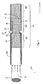
- FIG. 1 depicts a cigarette 1 comprising a tobacco rod 3 and a multi-section filter 5, which can be held together by tipping paper 15 as is well-known in the art.
- the multi-section filter 5 is made up of three filter sections 5A, 5B, 5C arranged end-to-end.
- filter 5 comprises a grooved middle filter section 5A, a mouth-end filter section 5B, and a filter section 5C adjacent to the tobacco rod 3.
- the grooved filter section 5A is arranged in the middle between the other two filter sections 5B, 5C (with respect to the main cylindrical axis of the filter).
- the grooves 7 are located on the outside of the filter and extend in a generally axial direction.
- the filter section 5A is provided with a plurality of grooves 7, which are distributed around the circumference of filter section 5A.
- the grooves extend along substantially the length of the middle filter section 5A, from near the tobacco end section 5C to the mouth-end section 5B. However, the grooves do not extend into the tobacco-end filter section 5C or into the mouth end filter section 5B.
- the grooves 7 are separated from the tobacco-end filter section 5C by an impermeable barrier 9. Likewise, the grooves are separated from the body 11 of the middle filter section 5A by an impermeable layer 6. However, the grooves are open at the end opposite barrier 9 to allow air or other gas/vapour flowing along groove 7 to pass into the mouth-end filter section 5B.
- the impermeable layer 6 comprises a non-porous plug-wrap which surrounds (the circumference of) the body of filter material 11 in filter section 5A.
- This filter material 11 may comprise any suitable filter material or structure, for example cellulose acetate tow, paper, etc.
- the filter material may be provided with one or more additives, such as activated carbon, etc.
- the non-porous plug-wrap 6 may be corrugated to define grooves 7 (with the corrugations running parallel to the cylindrical axis of the filter).
- the filter material 11 inside the non-porous plug-wrap will generally deform to occupy all the space inside the non-porous plug-wrap.
- the individual filter sections are combined with a porous outer plug-wrap 13.
- This outer plug-wrap then sits on the ridges or raised corrugations of the inner plug-wrap, with the grooves being formed between the outer plug-wrap and the lower (reduced radius) portions of the inner plug-wrap 6.
- a smoker draws on the mouth-end section of the filter 5B. This causes smoke from the combustion end 2 of the tobacco rod to travel through the filter rod towards the smoker (as indicated by the arrows). The smoke travels through the remaining (unburnt) tobacco rod 3 before entering the filter 5. The smoke first passes through the tobacco-end filter section 5C, then through the body 11 of the middle filter section (since the smoke is unable to pass into the grooves 7). The smoke then exits the filter 5 through the mouth-end filter section 5B.
- the flow resistance through the ventilation holes 17 and along grooves 7 is low compared to the flow resistance through the body portion 11 of the filter, for example.
- the air After the air has entered a groove 7 as indicated by arrow A, the air is constrained to travel along the groove, as indicated by arrow B, since the groove walls, which are formed by non-porous inner plug-wrap 6 and tipping 15 papers, plus barrier 9, are generally impermeable. Accordingly, the incoming air finally exits the grooves 7 into the mouth-end filter portion 5B, where it mixes with and dilutes the mainstream smoke from combustion zone 2.
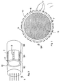
- Figure 2 is a further schematic view of the embodiment of Figure 1 .
- Figure 2 is a perspective view illustrating the circumferential distribution of grooves 7 around a filter.
- Figure 2 specifically shows the ventilation holes 17 located over the ends of the grooves 7 remote from the mouth-end of the filter.
- these ventilation holes 17 are formed via laser perforation, but any other suitable mechanism may be used.
- the ventilation holes may be sited directly over the grooves (as shown schematically in Figure 2 ) or sited in a random band or bands which may or may not coincide with the grooves.
- Figure 3 is a cross-section through the filter 5 at the location of the ventilation holes 17 in the outer tipping 15. According to the embodiment shown in Figure 3 the ventilation holes in the outer tipping do not all coincide with the grooves. Although there is a gap shown in Figure 3 for clarity between the inner plug-wrap 6 and the outer plug-wrap 13, and likewise a gap between the outer plug-wrap 13 and the tipping paper 15, it will be appreciated that in practice no appreciable gaps are present, except for the grooves themselves.
- grooves 7, as shown in Figures 2, 3 , and 4 is by way of example only. Other embodiments may have a different number and/or distribution of grooves.
- Providing the grooves 7 in the filter 5 allows a separation between: (a) the location of the ventilation holes for incoming air, now at the end of the middle filter section 5A remote from the mouth; and (b) the location of the point where the ventilating air joins the main smoke flow, now at the junction between the middle filter section 5A and the mouth-end filter section 5B.
- the ability to separate these two locations gives more flexibility in the design and control of filter 5.
- the ventilation holes are located at least about 11mm from the mouth end of the filter, for example between about 12mm and about 25mm from the mouth end.
- the filter material may comprise adsorbent material such as activated carbon or other suitable adsorbents.
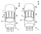
- FIG. 4a and 4b Two alternative embodiments are illustrated in Figure 4a and 4b .
- additional ventilation holes are provided for the middle (grooved) filter section 5A.
- the additional ventilation holes 17A are provided at the far end of the middle filter section 5A, remote from the mouth; i.e. at the same end as the ventilation holes 17 into the grooves.
- the circumferential positioning of these holes 17A is such that they do not lie above the grooves.
- the air passing through the ventilation holes 17A does not bypass the filter material 11 of the middle filter section 5A, in contrast to the air entering through the ventilation holes 17, which is channelled by the grooves directly towards the mouth-end filter section 5B.
- the configurations of Figures 4a and 4b therefore provide two effective positions of entry for ventilating air, and so allow enhanced control of smoke and filter properties.
- the additional ventilation provides increased dilution of the mainstream smoke, including carbon monoxide and tar.
- the additional ventilation also increases the flow speed through the filter body 11, which decreases the filtration efficiency for materials such as tar.
- the additional ventilation holes 17B are provided at the mouth end of the grooved section 5A.
- the air passing through ventilation holes 17B therefore enters the main portion of filter 5 at a slightly upstream position to the air entering through ventilation holes 17 (and travelling along grooves 7).
- the overall result of the configurations of Figure 4a and 4b are to provide increased ventilation and hence increased smoke dilution compared to the arrangement of Figure 2 .
- FIG. 4a and 4b may be combined in a single embodiment that has both additional ventilation holes 17A and additional ventilation holes 17B. That is, additional ventilation holes at both ends of the grooved filter section 5A. It will also be appreciated that the ventilation provided either into the grooves 17, or as additional ventilation via perforations 17A or 17B, can be provided in a wide band or zone across part or all of the filter section 5A.
- the number of filter sections may be different from the 3 filter sections shown in Figures 1 , 2 and 4 .
- some multi-segment filters may only have 2 filter sections, while other multi-segment filters may have four, five or more filter sections.
- the grooved filter section is separated from the mouth end of the filter by at least one other filter section (to help avoid lip blocking).
- the grooves in Figures 1-4 have been shown extending the full length of the grooved filter section 5A, in other embodiments the grooves may extend only partway along the grooved filter section. In such a case the grooves may start away from the tobacco end of the section and/or terminate away from the mouth end of the section. Conversely, in some cases the grooves may extend (wholly or partially) across multiple filter sections.
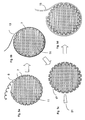
- Figure 5 illustrates a method of manufacturing a filter in accordance with one embodiment of the invention.
- a sheet of non-permeable plug-wrap material 6 is corrugated or embossed to produce the grooves 7.
- the grooved material is wrapped around a cylinder of filter material 11 ( Figure 5a ).
- the grooves shown in Figure 5 have a U-shaped profile, but may have any other suitable profile, for example, V-shaped, or with square corners at the top and bottom. While the grooves ( Figure 5a ) are shown as being on the inner surface of plugwrap material 6, hence creating channels within the body of the filter material itself, it will be appreciated that channels may form externally to the main body of the filter material 11.
- the number and spacing of the grooves may vary from one embodiment to another. For example, there may be continuous V-shaped grooves (no spacing), so that the inner plug-wrap in effect has a zigzag configuration.
- a layer of outer plug-wrap material 13 is now wrapped around the outside of the grooved filter rod ( Figure 5b ).
- the grooves 7 in the inner plug-wrap material therefore become closed channels between the inner plug-wrap 6 and the outer plug-wrap 13.
- the outer plug-wrap 13 may be used to bind the filter section 11 with one or more other filter sections if so desired.
- Additional ventilation holes 17 may be formed in the outer plug-wrap 13 using laser 51 ( Figure 5c ). Although the outer plug-wrap 13 is shown separated from the inner plug-wrap 6 for clarity, again they will in practice be touching, as shown in Figure 5b , except where the grooves are located. The ventilation holes 17 coincide with the grooves 7, and therefore provide entrance holes for air to pass into the grooves. Additional ventilation holes may be provided which are not linked to the grooves (as illustrated above in Figures 4a and 4b ). Such ventilation holes may be formed passing through both the outer and also the inner plug-wrap as well as the outer tipping paper.
- a further layer of sheet material 15, commonly known as tipping paper, may be subsequently applied to the ventilated wrapper and overlays the grooved filter section 5A ( Figure 5d ).
- the tipping paper may be used to join the combined filter sections to the tobacco rod thereby securing together the components of a complete cigarette 1.
- the tipping paper may be permeable (pre-perforated) or impermeable. Impermeable tipping paper may be ventilated by means of on-machine laser techniques.
- on-line continuous grooving is applied to a filter rod, for example by wrapping the impermeable inner plug-wrap around the whole length of the rod, then grooving by passing through a shaped former.
- This filter rod can then be segmented for combination with other segments in a multi-element filter.
- discontinuous grooving may be applied to the filter rod, for example by impressing discontinuous grooves into the wrapped rod, using heated formers.
- the grooves are closed to the element on the tobacco side of the grooved section by any suitable technique.
- an outer annulus made of plastic may be inserted between the two elements (as illustrated in Figure 1 ).
- Another possibility for this sealing is to apply glue to the end of the groove furthest from the mouth.
- the filter segments are combined in such a way that the grooves do not reach the end of the tobacco side of the filter section.
- the grooves or channels may be formed by any of the known methods.
- the grooves may be formed directly in the filter material, such as by heat forming of cellulose acetate filters.
- the non-permeable inner plug-wrap may be shaped or embossed prior to being wrapped around a cylinder of filter material.
- continuous grooving is applied, by any suitable means, to a length of filter rod, which is subsequently segmented. In other embodiments, grooving is applied to pre-sized filter sections.
- a layer of permeable plug-wrap may be used to further encapsulate the grooved filter section.
- This permeable plug-wrap may also function to combine two or more filter sections.
- the barrier 9 may be formed by any suitable material and/or mechanism.
- one option is to apply a spot or band of glue or other non-permeable material into each groove 7.
- Another option is to provide an annulus of non-permeable material, e.g. plastic, that goes around near the circumference of the filter 5, and separates (and blocks off) the grooves 7 from the tobacco-end filter section 5C.
- Another possibility is to provide barrier 9 by hot melt fusion of the filter material 11.
- the tipping paper may be used to join the combined filter to the tobacco rod.
- the tipping paper may be adhered to the filter and the tobacco rod, by any suitable means, but may retain a largely non-adhered portion over the grooved section 5A.
- tipping paper perforations may be provided by means of a laser, or by other suitable means. Tipping paper may be perforated before or after being bound to the filter.
- the tipping paper is adhered to the three filter sections using a skip gap gluing technique such that a largely glue free area is positioned between the ventilation holes and the plug-wrap overlying the grooves. It will be appreciated that using adhesives to join the three layers (inner plug-wrap, outer plug-wrap and tipping) together at the position where the ventilation holes occur would result in blocking of the airflows and therefore the area is left predominantly non-glued.
Landscapes
- Cigarettes, Filters, And Manufacturing Of Filters (AREA)
Priority Applications (1)
| Application Number | Priority Date | Filing Date | Title |
|---|---|---|---|
| PL09754141T PL2328431T3 (pl) | 2008-05-30 | 2009-05-27 | Filtr do wyrobu do palenia |
Applications Claiming Priority (2)
| Application Number | Priority Date | Filing Date | Title |
|---|---|---|---|
| GBGB0809865.9A GB0809865D0 (en) | 2008-05-30 | 2008-05-30 | Filter for a smoking article |
| PCT/GB2009/050573 WO2009144496A1 (en) | 2008-05-30 | 2009-05-27 | Filter for a smoking article |
Publications (2)
| Publication Number | Publication Date |
|---|---|
| EP2328431A1 EP2328431A1 (en) | 2011-06-08 |
| EP2328431B1 true EP2328431B1 (en) | 2013-05-22 |
Family
ID=39637873
Family Applications (1)
| Application Number | Title | Priority Date | Filing Date |
|---|---|---|---|
| EP09754141.1A Not-in-force EP2328431B1 (en) | 2008-05-30 | 2009-05-27 | Filter for a smoking article |
Country Status (20)
| Country | Link |
|---|---|
| US (1) | US9066542B2 (ru) |
| EP (1) | EP2328431B1 (ru) |
| JP (1) | JP5883291B2 (ru) |
| KR (1) | KR20110013528A (ru) |
| CN (1) | CN102046034A (ru) |
| AR (1) | AR074144A1 (ru) |
| AU (1) | AU2009252940A1 (ru) |
| BR (1) | BRPI0913104A2 (ru) |
| CA (1) | CA2725121C (ru) |
| CL (1) | CL2009001292A1 (ru) |
| ES (1) | ES2425426T3 (ru) |
| GB (1) | GB0809865D0 (ru) |
| MX (1) | MX2010013126A (ru) |
| MY (1) | MY169777A (ru) |
| PL (1) | PL2328431T3 (ru) |
| RU (2) | RU2010153373A (ru) |
| TW (1) | TW201016149A (ru) |
| UA (1) | UA99657C2 (ru) |
| WO (1) | WO2009144496A1 (ru) |
| ZA (1) | ZA201008495B (ru) |
Cited By (1)
| Publication number | Priority date | Publication date | Assignee | Title |
|---|---|---|---|---|
| CN109619671A (zh) * | 2018-11-22 | 2019-04-16 | 湖北中烟工业有限责任公司 | 一种具有高透气度的卷烟 |
Families Citing this family (14)
| Publication number | Priority date | Publication date | Assignee | Title |
|---|---|---|---|---|
| GB0821803D0 (en) * | 2008-12-01 | 2009-01-07 | British American Tobacco Co | Smoking article filter |
| JP2011205917A (ja) | 2010-03-29 | 2011-10-20 | British American Tobacco Japan Kk | 換気レベルを変えられる喫煙品 |
| GB201012732D0 (en) * | 2010-07-29 | 2010-09-15 | British American Tobacco Co | Smoking article filter |
| GB201016387D0 (en) * | 2010-09-29 | 2010-11-10 | Filtrona Int Ltd | Tobacco smoke filter |
| GB201110863D0 (en) | 2011-06-27 | 2011-08-10 | British American Tobacco Co | Smoking article filter and insertable filter unit thereof |
| GB201112466D0 (en) * | 2011-07-20 | 2011-08-31 | British American Tobacco Co | Smoking article |
| GB201114897D0 (en) * | 2011-08-30 | 2011-10-12 | British American Tobacco Co | Smoking article and method of manufacturing a smoking article |
| CN102511929A (zh) * | 2011-11-10 | 2012-06-27 | 云南正邦生物技术有限公司 | 一种通风固形复合嘴棒及其制备方法 |
| GB201207211D0 (en) * | 2012-04-25 | 2012-06-06 | British American Tobacco Co | Smoking articles |
| GB201213786D0 (en) | 2012-08-01 | 2012-09-12 | Filtrona Filter Prod Dev Co | Tobacco smoke filter |
| CN107752123A (zh) * | 2017-10-19 | 2018-03-06 | 江苏中烟工业有限责任公司 | 一种含吸附材料的三段式加热不燃烧卷烟烟支 |
| KR102330291B1 (ko) * | 2018-07-04 | 2021-11-24 | 주식회사 케이티앤지 | 궐련 |
| US11432581B2 (en) | 2018-09-07 | 2022-09-06 | Altria Client Services Llc | Capsule containing a matrix, device with the matrix, and method of forming the matrix |
| JP2022552767A (ja) * | 2019-10-28 | 2022-12-20 | ジェイティー インターナショナル エス.エイ. | エアロゾル発生物品用フィルタコンポーネント |
Family Cites Families (34)
| Publication number | Priority date | Publication date | Assignee | Title |
|---|---|---|---|---|
| GB1308661A (en) | 1970-02-21 | 1973-02-21 | Cigarette Components Ltd | Device for treating tobacco smoke |
| US3768489A (en) | 1970-10-05 | 1973-10-30 | Eastman Kodak Co | Tobacco smoke filter |
| US3752165A (en) | 1971-12-20 | 1973-08-14 | G Harllee | Smoke filter plug and process and cigarette made therefrom |
| GB1508084A (en) | 1976-03-17 | 1978-04-19 | British American Tobacco Co | Tobacco-smoke filters |
| GB1585862A (en) | 1976-11-19 | 1981-03-11 | British American Tobacco Co | Tobacco-smoke filters |
| NO154418C (no) * | 1978-11-30 | 1986-09-17 | Siren M J O | Filtermateriale. |
| US4256122A (en) | 1979-04-11 | 1981-03-17 | Brown & Williamson Tobacco Corporation | Cigarette filter |
| TR21005A (tr) | 1980-11-21 | 1983-05-01 | Brown & Williamson Tobacco | Duman gecirmez bir sargi ile ihata edilmis mesamath bir filtre cubugunu ihtiva eden bir sigara filtresi |
| US4343319A (en) | 1980-11-28 | 1982-08-10 | Brown & Williamson Tobacco Corporation | Cigarette filter |
| US4362172A (en) | 1980-12-01 | 1982-12-07 | Brown & Williamson Tobacco Corporation | Cigarette filter |
| US4582071A (en) | 1980-12-22 | 1986-04-15 | Imperial Group Limited | Tipping assembly for an elongate smoking article |
| US4342322A (en) | 1980-12-22 | 1982-08-03 | Brown & Williamson Tobacco Corporation | Cigarette filter |
| BE891549A (fr) * | 1980-12-22 | 1982-04-16 | Imp Group Ltd | Assemblage de terminaison pour un article a fumer allonge |
| GB2090117B (en) | 1980-12-22 | 1985-08-21 | Imp Group Ltd | Ventilated cigarette tip |
| US4637409A (en) | 1981-05-07 | 1987-01-20 | American Filtrona Corporation | Tobacco smoke filter and method and apparatus for making same |
| US4552158A (en) | 1981-12-23 | 1985-11-12 | American Filtrona Corporation | Free air dilution smoke filter and method and apparatus for fabricating same |
| US4406294A (en) | 1982-02-16 | 1983-09-27 | Brown & Williamson Tobacco Corporation | Cigarette filter |
| NO157125C (no) | 1982-04-08 | 1988-06-01 | Filtrona Ltd | Sigarettfilterelement, alternativt med et omgivende, ventilerende munnstykkemateriale. |
| US4527573A (en) | 1982-11-05 | 1985-07-09 | Philip Morris Incorporated | Filter cigarette |
| US4527572A (en) | 1983-02-07 | 1985-07-09 | Brown & Williamson Tobacco Corporation | Tobacco smoke filters |
| US4542754A (en) | 1983-12-05 | 1985-09-24 | Brown & Williamson Tobacco Corporation | Filtered cigarette |
| US4557281A (en) | 1983-12-05 | 1985-12-10 | Brown & Williamson Tobacco Corporation | Filtered cigarette |
| US4580584A (en) | 1984-02-21 | 1986-04-08 | Brown & Williamson Tobacco Corporation | Cigarette filter |
| EP0167863B1 (de) * | 1984-06-20 | 1988-01-07 | H.F. & Ph.F. Reemtsma GmbH & Co | Variabel ventilierbare Filterzigarette |
| JPH0479875A (ja) | 1990-07-20 | 1992-03-13 | Japan Tobacco Inc | フイルタ付たばこ |
| US5178166A (en) | 1990-09-20 | 1993-01-12 | Philip Morris Incorporated | Filter cigarette |
| ES2201071T3 (es) | 1994-01-27 | 2004-03-16 | British American Tobacco (Investments) Limited | Mejoras introducidas en articulos de fumar. |
| JPH09316420A (ja) * | 1996-05-27 | 1997-12-09 | Daicel Chem Ind Ltd | 水溶性ホットメルト接着剤と、これを用いたたばこフィルター及びその製造方法 |
| JP3181248B2 (ja) | 1997-10-06 | 2001-07-03 | 日本たばこ産業株式会社 | フィルター付きシガレットおよびシガレット用フィルター |
| AU2006202993B2 (en) | 2001-12-18 | 2007-09-20 | British American Tobacco (Investments) Limited | Ventilated smoking article |
| ATE341234T1 (de) | 2001-12-18 | 2006-10-15 | Bat Cigarettenfab Gmbh | Filter für einen rauchbaren artikel |
| US7237558B2 (en) | 2003-09-30 | 2007-07-03 | R. J. Reynolds Tobacco Company | Filtered cigarette incorporating an adsorbent material |
| EP1797780A1 (en) | 2005-12-15 | 2007-06-20 | Gallaher Limited | Smoking article |
| US8424539B2 (en) | 2006-08-08 | 2013-04-23 | Philip Morris Usa Inc. | Smoking article with single piece restrictor and chamber |
-
2008
- 2008-05-30 GB GBGB0809865.9A patent/GB0809865D0/en not_active Ceased
-
2009
- 2009-05-26 CL CL2009001292A patent/CL2009001292A1/es unknown
- 2009-05-27 PL PL09754141T patent/PL2328431T3/pl unknown
- 2009-05-27 JP JP2011511095A patent/JP5883291B2/ja not_active Expired - Fee Related
- 2009-05-27 KR KR1020107029300A patent/KR20110013528A/ko not_active Application Discontinuation
- 2009-05-27 UA UAA201015597A patent/UA99657C2/ru unknown
- 2009-05-27 AU AU2009252940A patent/AU2009252940A1/en not_active Abandoned
- 2009-05-27 RU RU2010153373/12A patent/RU2010153373A/ru unknown
- 2009-05-27 MY MYPI2010005475A patent/MY169777A/en unknown
- 2009-05-27 TW TW098117576A patent/TW201016149A/zh unknown
- 2009-05-27 MX MX2010013126A patent/MX2010013126A/es active IP Right Grant
- 2009-05-27 US US12/995,232 patent/US9066542B2/en not_active Expired - Fee Related
- 2009-05-27 BR BRPI0913104A patent/BRPI0913104A2/pt not_active IP Right Cessation
- 2009-05-27 WO PCT/GB2009/050573 patent/WO2009144496A1/en active Application Filing
- 2009-05-27 CA CA2725121A patent/CA2725121C/en not_active Expired - Fee Related
- 2009-05-27 CN CN2009801201274A patent/CN102046034A/zh active Pending
- 2009-05-27 ES ES09754141T patent/ES2425426T3/es active Active
- 2009-05-27 RU RU2014122922/12U patent/RU148293U1/ru active
- 2009-05-27 EP EP09754141.1A patent/EP2328431B1/en not_active Not-in-force
- 2009-05-28 AR ARP090101918A patent/AR074144A1/es not_active Application Discontinuation
-
2010
- 2010-11-25 ZA ZA2010/08495A patent/ZA201008495B/en unknown
Cited By (1)
| Publication number | Priority date | Publication date | Assignee | Title |
|---|---|---|---|---|
| CN109619671A (zh) * | 2018-11-22 | 2019-04-16 | 湖北中烟工业有限责任公司 | 一种具有高透气度的卷烟 |
Also Published As
| Publication number | Publication date |
|---|---|
| MY169777A (en) | 2019-05-15 |
| AU2009252940A1 (en) | 2009-12-03 |
| JP5883291B2 (ja) | 2016-03-09 |
| AR074144A1 (es) | 2010-12-29 |
| CA2725121C (en) | 2014-01-07 |
| PL2328431T3 (pl) | 2013-10-31 |
| BRPI0913104A2 (pt) | 2016-01-05 |
| CA2725121A1 (en) | 2009-12-03 |
| TW201016149A (en) | 2010-05-01 |
| US9066542B2 (en) | 2015-06-30 |
| MX2010013126A (es) | 2011-01-14 |
| JP2011521634A (ja) | 2011-07-28 |
| KR20110013528A (ko) | 2011-02-09 |
| EP2328431A1 (en) | 2011-06-08 |
| RU148293U1 (ru) | 2014-11-27 |
| US20110155155A1 (en) | 2011-06-30 |
| WO2009144496A1 (en) | 2009-12-03 |
| CN102046034A (zh) | 2011-05-04 |
| ES2425426T3 (es) | 2013-10-15 |
| GB0809865D0 (en) | 2008-07-09 |
| RU2010153373A (ru) | 2012-07-10 |
| CL2009001292A1 (es) | 2010-10-01 |
| ZA201008495B (en) | 2014-05-28 |
| UA99657C2 (ru) | 2012-09-10 |
Similar Documents
| Publication | Publication Date | Title |
|---|---|---|
| EP2328431B1 (en) | Filter for a smoking article | |
| EP1093728B1 (en) | Filter for a cigarette and a filter-tipped cigarette | |
| CA2742396C (en) | Smoking article filter | |
| US4582071A (en) | Tipping assembly for an elongate smoking article | |
| WO2009077244A1 (en) | Recessed ventilation for smoking articles | |
| WO2007069091A2 (en) | Smoking article with coaxial tobacco rod | |
| CN106998795A (zh) | 吸烟制品、过滤器和制造吸烟制品的方法 | |
| EP2073651A1 (en) | Tobacco smoke filter | |
| GB2090117A (en) | Ventilated cigarette tip | |
| EP2854574B1 (en) | Smoking article with concentric filter | |
| KR20150099748A (ko) | 끽연류 | |
| KR20150096415A (ko) | 끽연류 |
Legal Events
| Date | Code | Title | Description |
|---|---|---|---|
| PUAI | Public reference made under article 153(3) epc to a published international application that has entered the european phase |
Free format text: ORIGINAL CODE: 0009012 |
|
| 17P | Request for examination filed |
Effective date: 20101222 |
|
| AK | Designated contracting states |
Kind code of ref document: A1 Designated state(s): AT BE BG CH CY CZ DE DK EE ES FI FR GB GR HR HU IE IS IT LI LT LU LV MC MK MT NL NO PL PT RO SE SI SK TR |
|
| AX | Request for extension of the european patent |
Extension state: AL BA RS |
|
| DAX | Request for extension of the european patent (deleted) | ||
| GRAP | Despatch of communication of intention to grant a patent |
Free format text: ORIGINAL CODE: EPIDOSNIGR1 |
|
| RIN1 | Information on inventor provided before grant (corrected) |
Inventor name: FIEBELKORN, RICHARD |
|
| GRAS | Grant fee paid |
Free format text: ORIGINAL CODE: EPIDOSNIGR3 |
|
| GRAA | (expected) grant |
Free format text: ORIGINAL CODE: 0009210 |
|
| AK | Designated contracting states |
Kind code of ref document: B1 Designated state(s): AT BE BG CH CY CZ DE DK EE ES FI FR GB GR HR HU IE IS IT LI LT LU LV MC MK MT NL NO PL PT RO SE SI SK TR |
|
| REG | Reference to a national code |
Ref country code: GB Ref legal event code: FG4D |
|
| REG | Reference to a national code |
Ref country code: CH Ref legal event code: EP Ref country code: CH Ref legal event code: NV Representative=s name: KIRKER AND CIE S.A., CH |
|
| REG | Reference to a national code |
Ref country code: RO Ref legal event code: EPE |
|
| REG | Reference to a national code |
Ref country code: AT Ref legal event code: REF Ref document number: 612701 Country of ref document: AT Kind code of ref document: T Effective date: 20130615 |
|
| REG | Reference to a national code |
Ref country code: IE Ref legal event code: FG4D |
|
| REG | Reference to a national code |
Ref country code: DE Ref legal event code: R096 Ref document number: 602009015915 Country of ref document: DE Effective date: 20130718 |
|
| PGFP | Annual fee paid to national office [announced via postgrant information from national office to epo] |
Ref country code: CH Payment date: 20130621 Year of fee payment: 5 |
|
| PGFP | Annual fee paid to national office [announced via postgrant information from national office to epo] |
Ref country code: FR Payment date: 20130626 Year of fee payment: 5 Ref country code: RO Payment date: 20130614 Year of fee payment: 5 |
|
| REG | Reference to a national code |
Ref country code: ES Ref legal event code: FG2A Ref document number: 2425426 Country of ref document: ES Kind code of ref document: T3 Effective date: 20131015 Ref country code: AT Ref legal event code: MK05 Ref document number: 612701 Country of ref document: AT Kind code of ref document: T Effective date: 20130522 |
|
| REG | Reference to a national code |
Ref country code: LT Ref legal event code: MG4D |
|
| PG25 | Lapsed in a contracting state [announced via postgrant information from national office to epo] |
Ref country code: AT Free format text: LAPSE BECAUSE OF FAILURE TO SUBMIT A TRANSLATION OF THE DESCRIPTION OR TO PAY THE FEE WITHIN THE PRESCRIBED TIME-LIMIT Effective date: 20130522 Ref country code: LT Free format text: LAPSE BECAUSE OF FAILURE TO SUBMIT A TRANSLATION OF THE DESCRIPTION OR TO PAY THE FEE WITHIN THE PRESCRIBED TIME-LIMIT Effective date: 20130522 Ref country code: PT Free format text: LAPSE BECAUSE OF FAILURE TO SUBMIT A TRANSLATION OF THE DESCRIPTION OR TO PAY THE FEE WITHIN THE PRESCRIBED TIME-LIMIT Effective date: 20130923 Ref country code: SI Free format text: LAPSE BECAUSE OF FAILURE TO SUBMIT A TRANSLATION OF THE DESCRIPTION OR TO PAY THE FEE WITHIN THE PRESCRIBED TIME-LIMIT Effective date: 20130522 Ref country code: IS Free format text: LAPSE BECAUSE OF FAILURE TO SUBMIT A TRANSLATION OF THE DESCRIPTION OR TO PAY THE FEE WITHIN THE PRESCRIBED TIME-LIMIT Effective date: 20130922 Ref country code: SE Free format text: LAPSE BECAUSE OF FAILURE TO SUBMIT A TRANSLATION OF THE DESCRIPTION OR TO PAY THE FEE WITHIN THE PRESCRIBED TIME-LIMIT Effective date: 20130522 Ref country code: GR Free format text: LAPSE BECAUSE OF FAILURE TO SUBMIT A TRANSLATION OF THE DESCRIPTION OR TO PAY THE FEE WITHIN THE PRESCRIBED TIME-LIMIT Effective date: 20130823 Ref country code: FI Free format text: LAPSE BECAUSE OF FAILURE TO SUBMIT A TRANSLATION OF THE DESCRIPTION OR TO PAY THE FEE WITHIN THE PRESCRIBED TIME-LIMIT Effective date: 20130522 Ref country code: NO Free format text: LAPSE BECAUSE OF FAILURE TO SUBMIT A TRANSLATION OF THE DESCRIPTION OR TO PAY THE FEE WITHIN THE PRESCRIBED TIME-LIMIT Effective date: 20130822 |
|
| REG | Reference to a national code |
Ref country code: PL Ref legal event code: T3 |
|
| REG | Reference to a national code |
Ref country code: NL Ref legal event code: VDEP Effective date: 20130522 |
|
| PG25 | Lapsed in a contracting state [announced via postgrant information from national office to epo] |
Ref country code: HR Free format text: LAPSE BECAUSE OF FAILURE TO SUBMIT A TRANSLATION OF THE DESCRIPTION OR TO PAY THE FEE WITHIN THE PRESCRIBED TIME-LIMIT Effective date: 20130522 Ref country code: BG Free format text: LAPSE BECAUSE OF FAILURE TO SUBMIT A TRANSLATION OF THE DESCRIPTION OR TO PAY THE FEE WITHIN THE PRESCRIBED TIME-LIMIT Effective date: 20130822 |
|
| PGFP | Annual fee paid to national office [announced via postgrant information from national office to epo] |
Ref country code: PL Payment date: 20130612 Year of fee payment: 5 |
|
| PG25 | Lapsed in a contracting state [announced via postgrant information from national office to epo] |
Ref country code: LV Free format text: LAPSE BECAUSE OF FAILURE TO SUBMIT A TRANSLATION OF THE DESCRIPTION OR TO PAY THE FEE WITHIN THE PRESCRIBED TIME-LIMIT Effective date: 20130522 |
|
| PGFP | Annual fee paid to national office [announced via postgrant information from national office to epo] |
Ref country code: IT Payment date: 20130625 Year of fee payment: 5 |
|
| PG25 | Lapsed in a contracting state [announced via postgrant information from national office to epo] |
Ref country code: CZ Free format text: LAPSE BECAUSE OF FAILURE TO SUBMIT A TRANSLATION OF THE DESCRIPTION OR TO PAY THE FEE WITHIN THE PRESCRIBED TIME-LIMIT Effective date: 20130522 Ref country code: DK Free format text: LAPSE BECAUSE OF FAILURE TO SUBMIT A TRANSLATION OF THE DESCRIPTION OR TO PAY THE FEE WITHIN THE PRESCRIBED TIME-LIMIT Effective date: 20130522 Ref country code: BE Free format text: LAPSE BECAUSE OF FAILURE TO SUBMIT A TRANSLATION OF THE DESCRIPTION OR TO PAY THE FEE WITHIN THE PRESCRIBED TIME-LIMIT Effective date: 20130522 Ref country code: SK Free format text: LAPSE BECAUSE OF FAILURE TO SUBMIT A TRANSLATION OF THE DESCRIPTION OR TO PAY THE FEE WITHIN THE PRESCRIBED TIME-LIMIT Effective date: 20130522 Ref country code: EE Free format text: LAPSE BECAUSE OF FAILURE TO SUBMIT A TRANSLATION OF THE DESCRIPTION OR TO PAY THE FEE WITHIN THE PRESCRIBED TIME-LIMIT Effective date: 20130522 |
|
| REG | Reference to a national code |
Ref country code: IE Ref legal event code: MM4A |
|
| PG25 | Lapsed in a contracting state [announced via postgrant information from national office to epo] |
Ref country code: MC Free format text: LAPSE BECAUSE OF FAILURE TO SUBMIT A TRANSLATION OF THE DESCRIPTION OR TO PAY THE FEE WITHIN THE PRESCRIBED TIME-LIMIT Effective date: 20130522 Ref country code: NL Free format text: LAPSE BECAUSE OF FAILURE TO SUBMIT A TRANSLATION OF THE DESCRIPTION OR TO PAY THE FEE WITHIN THE PRESCRIBED TIME-LIMIT Effective date: 20130522 |
|
| PLBE | No opposition filed within time limit |
Free format text: ORIGINAL CODE: 0009261 |
|
| STAA | Information on the status of an ep patent application or granted ep patent |
Free format text: STATUS: NO OPPOSITION FILED WITHIN TIME LIMIT |
|
| 26N | No opposition filed |
Effective date: 20140225 |
|
| PG25 | Lapsed in a contracting state [announced via postgrant information from national office to epo] |
Ref country code: IE Free format text: LAPSE BECAUSE OF NON-PAYMENT OF DUE FEES Effective date: 20130527 |
|
| REG | Reference to a national code |
Ref country code: DE Ref legal event code: R097 Ref document number: 602009015915 Country of ref document: DE Effective date: 20140225 |
|
| REG | Reference to a national code |
Ref country code: HU Ref legal event code: AG4A Ref document number: E019691 Country of ref document: HU |
|
| PGFP | Annual fee paid to national office [announced via postgrant information from national office to epo] |
Ref country code: HU Payment date: 20130627 Year of fee payment: 5 |
|
| REG | Reference to a national code |
Ref country code: CH Ref legal event code: PL |
|
| PG25 | Lapsed in a contracting state [announced via postgrant information from national office to epo] |
Ref country code: RO Free format text: LAPSE BECAUSE OF NON-PAYMENT OF DUE FEES Effective date: 20140527 Ref country code: LI Free format text: LAPSE BECAUSE OF NON-PAYMENT OF DUE FEES Effective date: 20140531 Ref country code: CH Free format text: LAPSE BECAUSE OF NON-PAYMENT OF DUE FEES Effective date: 20140531 |
|
| PG25 | Lapsed in a contracting state [announced via postgrant information from national office to epo] |
Ref country code: HU Free format text: LAPSE BECAUSE OF NON-PAYMENT OF DUE FEES Effective date: 20140528 Ref country code: MT Free format text: LAPSE BECAUSE OF FAILURE TO SUBMIT A TRANSLATION OF THE DESCRIPTION OR TO PAY THE FEE WITHIN THE PRESCRIBED TIME-LIMIT Effective date: 20130522 |
|
| REG | Reference to a national code |
Ref country code: FR Ref legal event code: ST Effective date: 20150130 |
|
| PG25 | Lapsed in a contracting state [announced via postgrant information from national office to epo] |
Ref country code: IT Free format text: LAPSE BECAUSE OF NON-PAYMENT OF DUE FEES Effective date: 20140527 |
|
| PG25 | Lapsed in a contracting state [announced via postgrant information from national office to epo] |
Ref country code: FR Free format text: LAPSE BECAUSE OF NON-PAYMENT OF DUE FEES Effective date: 20140602 |
|
| PG25 | Lapsed in a contracting state [announced via postgrant information from national office to epo] |
Ref country code: CY Free format text: LAPSE BECAUSE OF FAILURE TO SUBMIT A TRANSLATION OF THE DESCRIPTION OR TO PAY THE FEE WITHIN THE PRESCRIBED TIME-LIMIT Effective date: 20130522 |
|
| PG25 | Lapsed in a contracting state [announced via postgrant information from national office to epo] |
Ref country code: MK Free format text: LAPSE BECAUSE OF FAILURE TO SUBMIT A TRANSLATION OF THE DESCRIPTION OR TO PAY THE FEE WITHIN THE PRESCRIBED TIME-LIMIT Effective date: 20130522 Ref country code: LU Free format text: LAPSE BECAUSE OF NON-PAYMENT OF DUE FEES Effective date: 20130527 |
|
| PG25 | Lapsed in a contracting state [announced via postgrant information from national office to epo] |
Ref country code: PL Free format text: LAPSE BECAUSE OF NON-PAYMENT OF DUE FEES Effective date: 20140527 |
|
| REG | Reference to a national code |
Ref country code: PL Ref legal event code: LAPE |
|
| REG | Reference to a national code |
Ref country code: ES Ref legal event code: FD2A Effective date: 20160107 |
|
| PG25 | Lapsed in a contracting state [announced via postgrant information from national office to epo] |
Ref country code: ES Free format text: LAPSE BECAUSE OF NON-PAYMENT OF DUE FEES Effective date: 20140528 |
|
| PGFP | Annual fee paid to national office [announced via postgrant information from national office to epo] |
Ref country code: DE Payment date: 20190521 Year of fee payment: 11 |
|
| PGFP | Annual fee paid to national office [announced via postgrant information from national office to epo] |
Ref country code: TR Payment date: 20190520 Year of fee payment: 11 |
|
| PGFP | Annual fee paid to national office [announced via postgrant information from national office to epo] |
Ref country code: GB Payment date: 20190521 Year of fee payment: 11 |
|
| REG | Reference to a national code |
Ref country code: DE Ref legal event code: R119 Ref document number: 602009015915 Country of ref document: DE |
|
| GBPC | Gb: european patent ceased through non-payment of renewal fee |
Effective date: 20200527 |
|
| PG25 | Lapsed in a contracting state [announced via postgrant information from national office to epo] |
Ref country code: GB Free format text: LAPSE BECAUSE OF NON-PAYMENT OF DUE FEES Effective date: 20200527 |
|
| PG25 | Lapsed in a contracting state [announced via postgrant information from national office to epo] |
Ref country code: DE Free format text: LAPSE BECAUSE OF NON-PAYMENT OF DUE FEES Effective date: 20201201 |
|
| PG25 | Lapsed in a contracting state [announced via postgrant information from national office to epo] |
Ref country code: TR Free format text: LAPSE BECAUSE OF NON-PAYMENT OF DUE FEES Effective date: 20200527 |
|
| P01 | Opt-out of the competence of the unified patent court (upc) registered |
Effective date: 20230505 |